gbc winstone application - appendix 9 - surface water and ... · pdf fileappendix 9 surface...
TRANSCRIPT

Appendix 9
OTAIKA QUARRY - PROPOSED OVERBURDEN DISPOSAL AREA | Application for Land Use Consent and Assessment of Environmental Effects
Appendix 9
Surface Water and Hydrogeology Reports


Tonkin & Taylor Ltd | 105 Carlton Gore Rd, Newmarket, Auckland 1023, New Zealand PO Box 5271, Wellesley St, Auckland 1141 P +64-9-355 6000 F +64-9-307 0265 E [email protected]
Job No: 1000785 22 May 2017
GBC Winstone P O Box 17 195 Greenlane Auckland 1546 Attention: Ian Wallace Dear Ian
Otaika Quarry - Pegram Block Overburden Disposal
Assessment of Adverse Effects on Flood Risk
1 Introduction
Tonkin and Taylor Ltd (T+T) has been providing surface water hydrology design advice to GBC Winstone for the proposed overburden disposal area (OBDA) on the Pegram Block adjacent to the Otaika Quarry.
The advice provided to date pertains to the permanent diversion of a small stream required as part of the OBDA design and the assessment of the expected environmental effects related to the diversion.
The results of the assessment are reported in our preliminary surface water hydrology assessment1, which was prepared as one of a number of technical supporting documents to GBC Winstone’s application for resource consent.
The purpose of this memo is to address specific requirements for land use consent under the Whangarei District Plan that relate to earthworks being carried out in a flood susceptible area.
The specific requirements are covered in Clause a) of Rule 56.2.3 of the Whangarei District Plan:
1 Rule 56.2.3: Construction or alteration (excluding internal modification) of a building, construction of vehicular access to a building or allotment, or earthworks in a Flood Susceptible Area, is a permitted activity if:
a A report or certificate from a suitably qualified and experienced professional is provided to the Whangarei District Council which indicates that the activity is designed to accommodate the flood hazard and will not create any adverse effects upstream or downstream nor endanger human life;
Whangarei District Council identifies Flood Susceptible Areas within its boundaries by way of a series of Resource Area maps. The Pegram Block where GBC Winstone is proposing to place overburden fill is identified on Map 45R as a Flood Susceptible Area (refer Annotated Plan in Appendix A).
1 Tonkin +Taylor report prepared for GBC Winstone. Otaika Quarry – Proposed Overburden Disposal Area, Surface Water Hydrology Assessment, Dated May 2017, ref: 1000785v4

2
Tonkin & Taylor Ltd Otaika Quarry - Pegram Block Overburden Disposal Assessment of Adverse Effects on Flood Risk GBC Winstone
22 May 2017 Job No: 1000785
This memo draws heavily on our preliminary surface water hydrology report and should be read in conjunction with that report.
2 Proposed development
The proposed OBDA will involve filling of a broad gully with overburden material from the adjacent Otaika Quarry. The volume of placed fill is expected to be approximately 2.4 million m3 and will be placed intermittently over a period of 35 years.
Fill is expected to be placed over a number of earthworks seasons during the period of the consent. The proposed OBDA construction includes the diversion of a small natural stream channel (a tributary of the Te Waiiti Stream) that runs through the central part of the Pegram Block.
The diversion will be developed primarily by placing fill on the southern part of the site to form a channel against the existing natural slopes descending from the northern part of the site. To manage diversion channel grades, some sections of the channel will need to be cut into the natural ground.
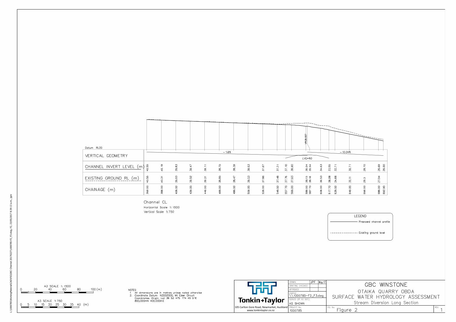
The stream diversion channel will incorporate an upper section that falls at approximately 2% grade, skirting the edge of the OBDA, and a steeper section at approximately 10% grade, that discharges surface water flows into an existing minor tributary channel that joins the main stream channel downstream of the proposed OBDA.
A plan showing the position of the proposed diversion, a long section of the channel and a series of cross sections are presented as Figures 1, 2 and 3 in our preliminary surface water hydrology report2.
3 Potential for adverse effects in a Flood Susceptible Area
The key considerations when assessing the potential adverse effects from the earthworks in a Flood Susceptible Area include:
Discharge in the channel during a design event;
Flow depth during a design event; and
Velocity of flow that could cause scour.
In dealing with these the following has been incorporated in the design:
1 The stream diversion channel geometry has been sized appropriately to convey the surface water flows from a 100 year ARI rainfall event from the modified catchment at the completion of the OBDA.
2 The channel capacity is significantly larger than that provided by the section of existing stream channel that will be filled over as part of the OBDA development.
3 The catchment area does not change significantly as a result of the proposed overburden placement.
4 The diverted stream channel will be protected from erosion by placement of suitable rock rip-rap protection.
5 The steeper (10% grade) diversion channel will discharge to the existing stream that has a slope of approximately 2%. An energy dissipation structure may be required to manage the transition and control erosion of the stream bed. Details of any structure required will be confirmed during the detailed design phase.
Our earlier report provides the detail of the analytical work undertaken and presents our design recommendations3. Overall, we conclude that with the design mitigations provided, the flow
2 Appendix B 3 Pages 9-11.


Appendix A : WDC Resource Area Map 45R Annotated

"
"
SSM 18
SSM 17
SCALE 1:10,000 Map No 45Whangarei District Council Operative Planning Map ´
Flood Susceptibile Areas
Mineral Extraction Areas
Mining Hazard Area 1
Mining Hazard Area 2
Mining Hazard Area 3
Notable Landscape Area
Outstanding Landscape Area
Outstanding Natural Features
Goat Control Areas
Scheduled Area or Overlay Area
Helicopter Hovering Area
Runway
Air Noise Boundary
Outer Control Boundary
Coastal Hazard 1
Coastal Hazard 2
Esplanade Priority Area
Building Line Restriction
" Sites of Significance to Maori
> Heritage Buildings, Sites, Objects (Built Heritage)
Scheduled Historic Area
Y Heritage Trees
Outstanding Natural Features
Coastline
Resource Areas
0 500250 m
The coastline indicates the mean high water spring (MHWS), which also indicates thejurisdictional boundary between the Northland Regional Council and the WhangareiDistrict Council
Northpower DisclaimerThis map is for indicative and planning purposes only.This map is not to be used in place of a cable location service. Northpower provides thisservice free of charge.
41
48
47
44
38
50
36
43
37
35
42
34
46
33
4540
67
66
69
51
68
64
49
55
62B62A
61B12
15
11
14
13
Date Modified: Tuesday, 27 September 2016


REPORT
Otaika Quarry - Proposed Overburden Disposal Area
Surface Water Hydrology Assessment
Prepared for
GBC Winstone
Prepared by
Tonkin & Taylor Ltd
Date
May 2017
Job Number
1000785.v4

Distribution:
GBC Winstone 1 copy
Tonkin & Taylor Ltd (FILE) 1 copy

Tonkin & Taylor Ltd Otaika Quarry - Proposed Overburden Disposal Area - Surface Water Hydrology Assessment GBC Winstone
May 2017 Job No: 1000785.v4
Table of contents
1 Introduction 4
2 Description of proposed development 4
3 Site overview 5
4 Assessment 6 4.1 Study methodology 6 4.2 Input data 7
4.2.1 Rainfall data 7 4.2.2 Catchment modelling 7 4.2.3 Stream profile and Diversion Channel profile 9
4.3 Results 9 4.3.1 Clean water management during construction (Design Case 1) 9 4.3.2 Diversion channel (Design Case 2) 10
5 Discussion 12 5.1 Clean water management during construction 12 5.2 Diversion channel 13
6 Conclusions 14
7 Applicability 14
Appendix A : HIRDS rainfall data
Appendix B : Concept Design Drawings
4
Tonkin & Taylor Ltd Otaika Quarry - Proposed Overburden Disposal Area - Surface Water Hydrology Assessment GBC Winstone
May 2017 Job No: 1000785.v4
1 Introduction
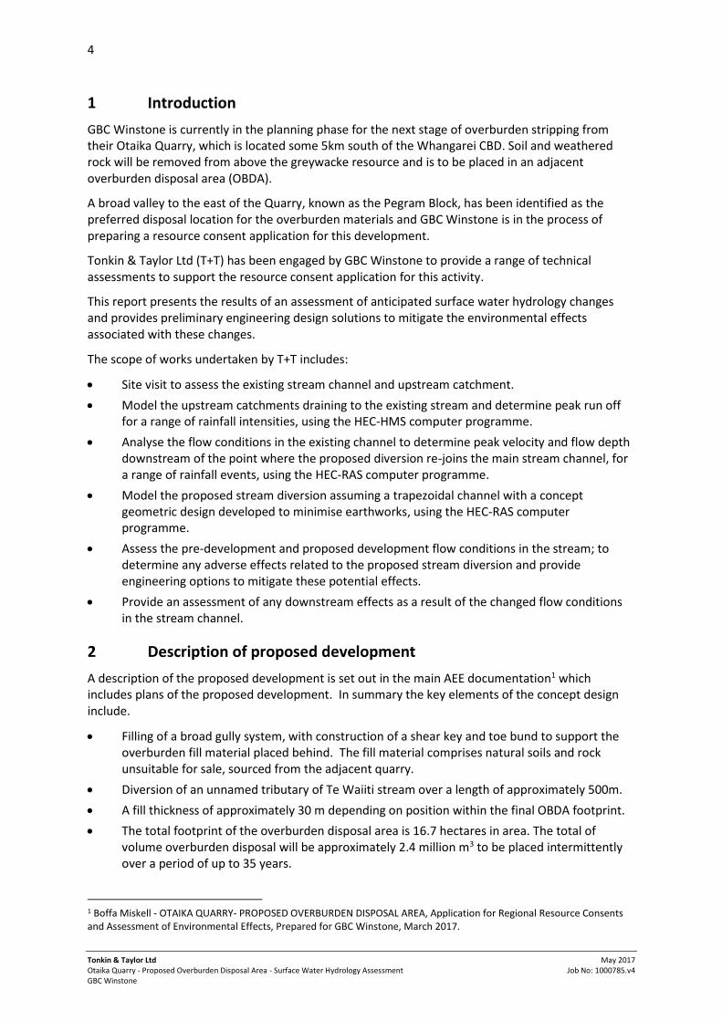
GBC Winstone is currently in the planning phase for the next stage of overburden stripping from their Otaika Quarry, which is located some 5km south of the Whangarei CBD. Soil and weathered rock will be removed from above the greywacke resource and is to be placed in an adjacent overburden disposal area (OBDA).
A broad valley to the east of the Quarry, known as the Pegram Block, has been identified as the preferred disposal location for the overburden materials and GBC Winstone is in the process of preparing a resource consent application for this development.
Tonkin & Taylor Ltd (T+T) has been engaged by GBC Winstone to provide a range of technical assessments to support the resource consent application for this activity.
This report presents the results of an assessment of anticipated surface water hydrology changes and provides preliminary engineering design solutions to mitigate the environmental effects associated with these changes.
The scope of works undertaken by T+T includes:
Site visit to assess the existing stream channel and upstream catchment.
Model the upstream catchments draining to the existing stream and determine peak run off for a range of rainfall intensities, using the HEC-HMS computer programme.
Analyse the flow conditions in the existing channel to determine peak velocity and flow depth downstream of the point where the proposed diversion re-joins the main stream channel, for a range of rainfall events, using the HEC-RAS computer programme.
Model the proposed stream diversion assuming a trapezoidal channel with a concept geometric design developed to minimise earthworks, using the HEC-RAS computer programme.
Assess the pre-development and proposed development flow conditions in the stream; to determine any adverse effects related to the proposed stream diversion and provide engineering options to mitigate these potential effects.
Provide an assessment of any downstream effects as a result of the changed flow conditions in the stream channel.
2 Description of proposed development
A description of the proposed development is set out in the main AEE documentation1 which includes plans of the proposed development. In summary the key elements of the concept design include.
Filling of a broad gully system, with construction of a shear key and toe bund to support the overburden fill material placed behind. The fill material comprises natural soils and rock unsuitable for sale, sourced from the adjacent quarry.
Diversion of an unnamed tributary of Te Waiiti stream over a length of approximately 500m.
A fill thickness of approximately 30 m depending on position within the final OBDA footprint.
The total footprint of the overburden disposal area is 16.7 hectares in area. The total of volume overburden disposal will be approximately 2.4 million m3 to be placed intermittently over a period of up to 35 years.
1 Boffa Miskell - OTAIKA QUARRY- PROPOSED OVERBURDEN DISPOSAL AREA, Application for Regional Resource Consents and Assessment of Environmental Effects, Prepared for GBC Winstone, March 2017.

5
Tonkin & Taylor Ltd Otaika Quarry - Proposed Overburden Disposal Area - Surface Water Hydrology Assessment GBC Winstone
May 2017 Job No: 1000785.v4
Placement of the overburden will take place over the 35-year duration of consent with individual earthworks seasons likely to occur every 3 - 4 years (depending on market demand) and lasting for approximately 6 - 8 months.
The stream diversion is to be formed by the placement of overburden materials against the naturally sloping ground, minimising the amount of cut required to achieve the design channel width.
During the initial phases of the enabling works filling will need to take place over the existing stream channel to allow access to the stream diversion site. This will block the stream channel, prior to the construction of the diversion. In addition to the main stream channel that will be diverted around the OBDA, there are a further 3 catchments that currently discharge seepage and surface water flow via gullies into the main channel. These minor gullies will also be blocked by the construction of the OBDA. The main stream channel will only be blocked during the initial phases of the enabling works, until the diversion is established, whereas the three minor catchments will be affected for the full life of the OBDA.
Connectivity of the surface water flow paths will be maintained using 110 mm diameter subsoil pipes below the placed overburden, with upstream detention provided for high intensity events that exceed the capacity of the 110 mm diameter pipes. For each flow path there will be at least two subsoil pipes provided, one solid to convey surface water runoff from the upstream side of the OBDA, one slotted to pick up groundwater seepages into the former gully channels.
The upstream detention will be isolated from the OBDA by the construction of a bund in each contributing catchment, ensuring that clean and dirty water do not mix. The bunds will be moved upstream as the OBDA footprint is extended in future earthworks seasons. Over time, as the OBDA is progressively stabilized, surface water flow will be reinstated across the finished OBDA landform, draining to the stream diversion.
3 Site overview
The proposed diversion works are to be constructed on the Pegram Block, immediately east of the existing pit as shown in Figure 3-1 below:
Figure 3-1: Site plan showing diversion and early stage filling

6
Tonkin & Taylor Ltd Otaika Quarry - Proposed Overburden Disposal Area - Surface Water Hydrology Assessment GBC Winstone
May 2017 Job No: 1000785.v4
The catchment that drains to the existing stream generally comprises pasture on gently undulating terrain. There is some vegetation along sections of the existing stream channel. The overall catchment is bounded on the north side by the Acacia Drive gated community, and on the south by Quarry Road, a private road providing access to the quarry. The catchment is bounded to the east by State Highway 1 and the Smeaton Drive residential community; and to the west by the existing quarry pit.
The overall catchment area is approximately 51 hectares. Surface water flows within this catchment are conveyed through the existing stream which runs from the North West to the South East of the catchment, where it discharges into a 1.2 m diameter concrete culvert under Quarry Road.
The portion of the catchment that will eventually drain to the stream diversion on completion of the OBDA is 29.5 ha.
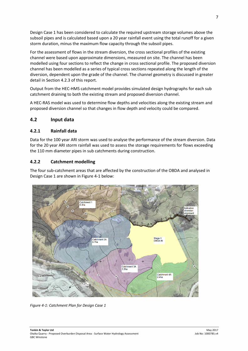
The portion of the catchment that will drain to the diverted section of the stream during initial OBDA construction is 5.3 ha (Catchment 1).
The three catchments that are to be temporarily conveyed below the OBDA by subsoil pipes are sized 6.7 ha (Catchment 2A), 3.8 ha (Catchment 3A) and 2.4 ha (Catchment 4A). As the OBDA develops over time these catchments will reduce in size and be replaced by earthworks areas and eventually rehabilitated areas which will discharge to the stream diversion until the full 29.5 ha drains to the diversion.
4 Assessment
4.1 Study methodology
The study methodology has been developed to assess the three key design drivers identified in relation to the surface hydrology aspect of the project:
Potential change in downstream conditions following the creation of the diversion;
Potential for increased erosive effects from flow through the new channel; and
Required upstream detention volumes at the inlet to the subsoil pipes during fill placement.
The catchment topography was modelled from a 2 m Digital Terrain Model (DTM), supplied by GBC Winstone, in addition to published topographic maps. The topographic data was input into Global Mapper (a GIS software package) to generate catchment boundaries, long sections through the catchment and cross sections through the existing stream channel.
Storm rainfall data for a range of storm durations and average recurrence intervals (ARI) was obtained from the HIRDS (High Intensity Rainfall Data System) V3 database, published by the National Institute of Water and Atmospheric Research (NIWA). Refer to Appendix A for the rainfall data used in the analysis.
Catchment runoff was modelled using the HEC-HMS software, to generate hydrographs for design rainfall events. We have examined two design cases in our analyses:
Design Case 1: The short term scenario, during construction of the OBDA and stream diversion. The existing sub-catchments (1, 2A, 3A, 4A) are blocked by the construction of the OBDA and conveyed below the OBDA in subsoil pipes. Runoff in excess of the subsoil pipe capacity is detained upstream of the toe of the OBDA.
Design Case 2: The long term scenario, with the site fully rehabilitated. Runoff from all rehabilitated areas will drain to the stream diversion. This scenario is analysed for a 100 year ARI rainfall event.
7
Tonkin & Taylor Ltd Otaika Quarry - Proposed Overburden Disposal Area - Surface Water Hydrology Assessment GBC Winstone
May 2017 Job No: 1000785.v4
Design Case 1 has been considered to calculate the required upstream storage volumes above the subsoil pipes and is calculated based upon a 20 year rainfall event using the total runoff for a given storm duration, minus the maximum flow capacity through the subsoil pipes.
For the assessment of flows in the stream diversion, the cross sectional profiles of the existing channel were based upon approximate dimensions, measured on site. The channel has been modelled using four sections to reflect the change in cross sectional profile. The proposed diversion channel has been modelled as a series of typical cross sections repeated along the length of the diversion, dependent upon the grade of the channel. The channel geometry is discussed in greater detail in Section 4.2.3 of this report.
Output from the HEC-HMS catchment model provides simulated design hydrographs for each sub catchment draining to both the existing stream and proposed diversion channel.
A HEC-RAS model was used to determine flow depths and velocities along the existing stream and proposed diversion channel so that changes in flow depth and velocity could be compared.
4.2 Input data
4.2.1 Rainfall data
Data for the 100 year ARI storm was used to analyse the performance of the stream diversion. Data for the 20 year ARI storm rainfall was used to assess the storage requirements for flows exceeding the 110 mm diameter pipes in sub catchments during construction.
4.2.2 Catchment modelling
The four sub-catchment areas that are affected by the construction of the OBDA and analysed in Design Case 1 are shown in Figure 4-1 below:
Figure 4-1: Catchment Plan for Design Case 1

8
Tonkin & Taylor Ltd Otaika Quarry - Proposed Overburden Disposal Area - Surface Water Hydrology Assessment GBC Winstone
May 2017 Job No: 1000785.v4
The ground cover for the pre and post-development scenarios has been assessed from aerial photography and our site walkover. The ground cover for Catchment 1, is broken down in Table 1 below:
Table 1: Catchment 1 ground cover for current and future development scenarios
Ground cover Area (ha)
Impervious areas 0.6
Pasture 1.8
Trees 2.9
TOTAL 5.3
Catchments 2A, 3A and 4A are 100% pasture. There are some areas of trees and impervious areas which are considered negligible. As the OBDA develops during the course of the 35 year life, the clean water part of these catchments will be progressively reduced in size and replaced by earthworks areas that drain to site sediment controls, and eventually rehabilitated areas that drain to the diversion.
The required detention volumes at the inlet of the subsoil drains below the OBDA have been determined based upon a 20 year ARI event for the Design Case 1 catchment areas (Figure 4-1).
Runoff from the actively earth-worked areas of the OBDA will be detained within the OBDA as part of the erosion and sediment control regime for the development (prepared by others). It is noted that of the 16.7 ha eventually making up the OBDA surface, only 3ha will be exposed as bare soils at any one time with the remainder either yet to be constructed or already rehabilitated.
The catchment areas upon completion of the OBDA and rehabilitation of the landform form the basis of our Design Case 2 analyses. These catchments are shown in Figure 4-2.
Figure 4-2: Catchment Plan for Design Case 2

9
Tonkin & Taylor Ltd Otaika Quarry - Proposed Overburden Disposal Area - Surface Water Hydrology Assessment GBC Winstone
May 2017 Job No: 1000785.v4
The ground cover for Catchment 1 in Design Case 2 remains unchanged from that shown in Table 1. The ground covers for Catchments 2, 3, 4 and 5 are taken to be pasture, as they will form part of the rehabilitated landform.
4.2.3 Stream profile and Diversion Channel profile
Cross sections for the existing stream (representative of the entire stream network) were determined from a digital terrain model (DTM) and modified based on observations made on site. The areas that have been modified from the DTM data are at the downstream end of the catchment. Upstream sections were not observed on site due to access restrictions, so the DTM data was used in the HEC-RAS model.
The diversion channel has been developed to follow the existing surface profile as much as reasonably possible. In the upper part of the diversion, the vertical gradient is of the order of 2% as the channel runs along the northern extent of the OBDA. The gradient in the lower part of the diversion, where the diversion runs around the eastern extent of the OBDA is of the order of 10% which is based on the gradient of the existing sidling gully.
In the upper, flatter section of the diversion, the channel has been modelled as a 1m wide channel with 1 in 1.5 side slopes on the north side of the channel. On the south side of the channel, the channel is formed by placement of the OBDA fill. This will be a slope of the order of 1 in 2, as shown on Figure 3 of Appendix B (subject to detailed design).
In the steeper section, the channel has been modelled as 2 m wide with 1 in 1.5 side slopes, to mitigate the increased flow velocity that would occur in high intensity events, due to the steep grade of the channel.
Manning’s roughness values of 0.03 were used for the natural channel and surrounding area, with a roughness of 0.025 used for the engineered channel, based on a proposed rip rap channel lining.
Refer to Appendix B for drawings of the indicative stream profiles (Figure 2 and Figure 3).
4.3 Results
4.3.1 Clean water management during construction (Design Case 1)
Our modelling of the surface water flows from Catchments 1 and 2A, 3A and 4A concluded that a 6 hour duration was the critical case for the 20 year ARI rainfall event. The proposed 110mm diameter sub-soil pipes have an approximate conveyance capacity of 0.014 m3/s, which is considerably less than the peak flow from a 6 hour 20 year ARI storm. Therefore there will be some detention required at the inlet of each sub-soil pipe to keep clean water flows from spilling onto the developing OBDA. The calculated storage volumes required for a 20 year ARI event are outlined in Table 2 below.
Table 2: Storage volumes at sub-soil drainage inlets
Catchment Peak flow (m3/s) Total runoff for a 6hr 20 year ARI
event (m3) Required on-site storage volume (m3)
1 0.40 2,390 2,100
2A 0.50 3,015 2,700
3A 0.29 1,710 1,400
4A 0.18 1,080 800

10
Tonkin & Taylor Ltd Otaika Quarry - Proposed Overburden Disposal Area - Surface Water Hydrology Assessment GBC Winstone
May 2017 Job No: 1000785.v4
GBC Winstone has indicated that the upstream detention will be achieved by constructing a bund at each pipe inlet to isolate clean water from the contributing catchments from dirty water and bare soils on the OBDA. The bund will be moved upstream as the OBDA develops, with the size of the contributing catchments and volume of runoff being progressively reduced, for Catchments 2A, 3A and 4A. In the case of Catchment 1, the upstream detention will only be required in the first earthworks season of the enabling works, while the diversion channel is being established.
GBC Winstone has indicated that the detention volumes in Table 2 can be accommodated within the OBDA construction.
4.3.2 Diversion channel (Design Case 2)
The calculated total runoff results for Catchments 1 to 5 for a 100 year ARI event for pre and post development cases are presented (in the form of hydrographs) in Figure 4-3 and Figure 4-4. The calculated peak runoff values are specified in Table 3. These results indicate that a 3 hour storm duration generates the maximum runoff of 3.97 m3/s in Design Case 2 and 4.12 m3/s in the pre-development case. These results have been used to design the stream diversion channel.
Figure 4-3: HEC-HMS hydrograph results for Design Case 2 in 100 year ARI storm events
0.0
0.5
1.0
1.5
2.0
2.5
3.0
3.5
4.0
4.5
0 2 4 6 8 10 12 14
Dis
char
ge (
m3
/s)
Time (hours)
100 year ARI hydrograph for the stream diversion (Design Case 2)
01 Hour 02 Hour 03 Hour 06 Hour 12 Hour

11
Tonkin & Taylor Ltd Otaika Quarry - Proposed Overburden Disposal Area - Surface Water Hydrology Assessment GBC Winstone
May 2017 Job No: 1000785.v4
Figure 4-4: HEC-HMS hydrograph results for pre development case in 100 year ARI storm events
The diverted stream will initially convey flows from Catchment 1 during the development of the OBDA. The diversion has been designed to accommodate all Design Case 2 catchments as illustrated in Figure 4-2. The output of the HEC-RAS analysis for the diversion channel is summarised in Table 3 and 4 below:
Table 3 Flow comparison at downstream end of diversion (CH784)
Scenario Peak flow (m3/s)
Invert level (mRL)
Water level (mRL)
Depth (m) Velocity (m/s)
Froude number
Existing condition
4.12 23.05 24.23 1.18 2.93 1.03
Post OBDA rehabilitation
3.97 23.05 23.79 0.74 5.04 2.24
0.0
0.5
1.0
1.5
2.0
2.5
3.0
3.5
4.0
4.5
0 2 4 6 8 10 12 14
Dis
char
ge (
m3
/s)
Time (hours)
100 year ARI hydrograph for the existing stream (pre development case)
01 Hour 02 Hour 03 Hour 06 Hour 12 Hour

12
Tonkin & Taylor Ltd Otaika Quarry - Proposed Overburden Disposal Area - Surface Water Hydrology Assessment GBC Winstone
May 2017 Job No: 1000785.v4
Table 4 Flow characteristics through diverted stream (including points before and after diversion)
Chainage Existing Condition Velocity (m/s)
Existing Condition Water Level (mRL)
Post OBDA Rehab Velocity (m/s)
Post OBDA Rehab Invert Level (mRL)
Post OBDA Rehab Water Level (mRL)
Post OBDA Rehab Energy Level (mRL)
Post OBDA Rehab Energy Depth (m)
365 2.94 42.85 2.95 42.62 42.85 43.29 0.67
428 N/A N/A 2.35 40.55 40.81 41.09 0.54
483 N/A N/A 1.96 39.56 39.97 40.17 0.61
577 N/A N/A 2.32 37.86 38.46 38.74 0.86
671 N/A N/A 4.25 34.39 34.71 35.63 1.24
784 2.93 24.14 5.04 23.05 23.79 25.08 2.02
792 2.98 23.93 3.49 22.86 23.98 24.43 1.12
797 3.19 23.74 2.93 22.71 23.78 24.21 1.53
The velocity at the point where the diversion re-joins the natural channel is increased from 2.93 m/s to 5.04 m/s (see Table 3). Upon re-joining the existing channel, the channel flattens out and within the first 15 m of re-joining, the flow velocity is reduced to being comparable with the predevelopment scenario (see Table 4).
The diversion channel has a velocity in excess of 1 m/s for a 100 year ARI event, and has the potential to cause erosion of the channel, with consequent downstream effects. This will be mitigated in the design by armouring the channel with a rip rap channel lining (refer Figure 6, Appendix B).
In analysing the channel flow, the energy level along the diverted stream was also considered (see Table 4). The results show that some water jumps are to be expected, but based on the channel geometry, the flow is expected to be maintained within the channel.
5 Discussion
5.1 Clean water management during construction
As discussed previously, during the first earthworks season it is proposed to install one or more 110 mm pipes below the placed fill material to maintain connectivity of the main stream channel, prior to the construction of the permanent diversion. Furthermore, catchments 2A, 3A and 4A all drain via gullies which will be blocked by the OBDA construction, with connectivity to the stream channel maintained by the construction of non-perforated sub-soil pipes below the OBDA. The minimum required storage volumes for a 20 year ARI rainfall event for each catchment are presented in Table 4 of this report.

13
Tonkin & Taylor Ltd Otaika Quarry - Proposed Overburden Disposal Area - Surface Water Hydrology Assessment GBC Winstone
May 2017 Job No: 1000785.v4
Detention of clean water flows exceeding the capacity of the 110mm diameter pipes will be achieved by the construction of a bund around the pipe inlet to isolate clean water runoff from the contributing catchments from dirty water and bare soil areas from the OBDA. A 20 year ARI rainfall event is considered to be an appropriate design event on the basis that as the OBDA footprint is extended, the bunds will be moved and the contributing catchments will be progressively reduced in size. The subsoil pipe for Catchment 1 will only be in place for one earthworks season until the diversion channel is established.
The outlet velocity of the 110mm pipes, when running at full capacity, will be of the order of 1.5 m/s. A rock apron will be constructed at the outlet of these pipes to provide energy dissipation of these flows and prevent scour of the area downstream of the outlets, prior to discharge back into the main channel. A concept design of the rock apron is shown in Figure 6 of Appendix B. This design has been used previously by GBC Winstone on other quarry sites.
During construction the quarry operator or site supervisor will monitor upcoming weather forecasts and there is the ability to intercede to reduce the risk of uncontrolled discharge across the OBDA in events that may exceed a 20 year ARI event.
As part of their erosion and sediment controls, GBC Winstone will manage the control of surface water from the area of bare soils (3 ha maximum) that will be generated during the placement of overburden within the OBDA, as set out in their erosion and sediment control management plan.
The erosion and sediment control plan being developed for the placement of fill should consider the possibility of surface water from events exceeding a 20 year ARI to be detained on the disturbed soils and allow a mechanism to treat this water appropriately after a large rainfall event to allow it to be discharged back to the stream as clean water.
5.2 Diversion channel
The diverted channel follows a different grade to the existing channel. As a consequence, the flow velocity in the diverted channel will differ from the existing channel, potentially causing additional erosive effects and unfavourable downstream flow conditions. This is to be mitigated by the modification of the channel geometry and armouring the channel and area where the diversion re-joins the existing channel
The analysis of the potential effects has been based upon a 1m wide channel base for the 2% grade section of the channel, and a 2m wide channel base for the 10% grade section of channel. Based upon these mitigations, the velocity at the point where the diversion re-joins the main stream channel is increased from 2.93 m/s in the pre development scenario, to 5.04 m/s in the post development scenario. Over the first 15 m downstream of this point, the grade of the channel flattens out and the flow in the post development scenario reduces to a level where it is comparable to the pre development scenario.
It can be assumed that if the flow conditions at the point just downstream from where the diversion re-joins the main stream do not differ significantly from the pre development scenario, there will not be a significant change to the downstream flow conditions as a consequence of the stream diversion.
The diversion channel will be protected from erosion by armouring the channel with a rip rap lining. Initial assessment of the channel indicates that a median rock diameter (D50) of the order of 500 mm would be required on the 10% grade section of the diversion, and 300mm on the 2% grade section. The channel armouring will be extended to include the 15m section of channel downstream of the re-joining point, over which the flow conditions are returned to their pre-development state.
Additional or alternative mitigations that are available for consideration in detailed design include incorporating energy dissipation measures into the diversion channel such as in channel storage,


15
Tonkin & Taylor Ltd Otaika Quarry - Proposed Overburden Disposal Area - Surface Water Hydrology Assessment GBC Winstone
May 2017 Job No: 1000785.v4
Appendix A : HIRDS rainfall data

High Intensity Rainfall System V3Results for Otaika QuarryDepth-Duration-Frequency results (produced on Thursday 24th of November 2016)Sitename: Otaika QuarryCoordinate system: NZMGEasting: 2628803Northing: 6603794
Rainfall depths (mm)
Duration
ARI (y) aep 10m 20m 30m 60m 2h 6h 12h 24h 48h 72h
1.58 0.633 9.9 14.2 17.5 25.2 34.3 56.2 76.7 104.7 128.2 144.4
2.00 0.500 10.7 15.3 18.9 27.2 37.0 60.6 82.6 112.6 138.0 155.4
5.00 0.200 13.5 19.4 23.9 34.3 46.7 76.1 103.6 141.1 172.8 194.6
10.00 0.100 15.8 22.6 27.9 40.1 54.5 88.6 120.5 163.8 200.6 225.9
20.00 0.050 18.3 26.2 32.4 46.5 63.1 102.5 139.2 189.0 231.5 260.7
30.00 0.033 19.9 28.6 35.3 50.6 68.7 111.4 151.2 205.2 251.3 283.0
40.00 0.025 21.2 30.3 37.5 53.8 72.9 118.2 160.3 217.4 266.3 299.9
50.00 0.020 22.2 31.8 39.3 56.3 76.4 123.7 167.7 227.4 278.5 313.7
60.00 0.017 23.0 33.0 40.8 58.5 79.3 128.4 174.0 235.9 288.9 325.3
80.00 0.012 24.4 35.1 43.3 62.1 84.1 136.1 184.4 249.8 306.0 344.6
100.00 0.010 25.6 36.7 45.4 65.0 88.1 142.4 192.9 261.2 320.0 360.3
Page 1 of 4High Intensity Rainfall System V3
24/11/2016https://hirds.niwa.co.nz/hirds_data/Otaika%20Quarry/NZMG/6603794/2628803/0,0,0...

Coefficients
c1 c2 c3 d1 d2 d3 e f
-0.0001 -0.0024 -0.0001 0.5207 0.4484 0.2930 0.2063 3.2262
Page 2 of 4High Intensity Rainfall System V3
24/11/2016https://hirds.niwa.co.nz/hirds_data/Otaika%20Quarry/NZMG/6603794/2628803/0,0,0...

Standard errors (mm)
Duration
ARI (y) aep 10m 20m 30m 60m 2h 6h 12h 24h 48h 72h
1.58 0.633 1.8 1.8 1.8 1.8 1.9 2.1 2.2 2.3 2.6 2.7
2.00 0.500 1.8 1.8 1.8 1.8 1.9 2.1 2.3 2.4 2.8 2.9
5.00 0.200 1.8 1.8 1.9 1.9 2.1 2.6 3.0 3.0 3.6 3.7
10.00 0.100 1.8 1.9 2.0 2.1 2.4 3.3 4.0 3.8 4.7 4.9
20.00 0.050 1.9 2.1 2.2 2.5 3.0 4.6 5.6 5.1 6.4 6.7
30.00 0.033 2.0 2.2 2.4 2.8 3.6 5.6 6.9 6.1 7.7 8.1
40.00 0.025 2.0 2.4 2.6 3.1 4.0 6.4 7.9 6.9 8.8 9.2
50.00 0.020 2.1 2.5 2.8 3.4 4.4 7.1 8.9 7.6 9.7 10.1
60.00 0.017 2.2 2.6 2.9 3.6 4.8 7.8 9.7 8.2 10.5 10.9
80.00 0.012 2.3 2.8 3.2 4.0 5.4 8.9 11.1 9.3 11.8 12.3
100.00 0.010 2.4 3.0 3.4 4.4 5.9 9.8 12.3 10.1 12.9 13.5
Page 3 of 4High Intensity Rainfall System V3
24/11/2016https://hirds.niwa.co.nz/hirds_data/Otaika%20Quarry/NZMG/6603794/2628803/0,0,0...

In preparing this table, all reasonable skill and care was exercised using best available data & methods. Nevertheless, NIWA does not accept any liability, whether direct, indirect or consequential, arising out the use of HIRDSV3. ©2016 NIWA
Privacy Statement ©2016 NIWA
Page 4 of 4High Intensity Rainfall System V3
24/11/2016https://hirds.niwa.co.nz/hirds_data/Otaika%20Quarry/NZMG/6603794/2628803/0,0,0...

Tonkin & Taylor Ltd Otaika Quarry - Proposed Overburden Disposal Area - Surface Water Hydrology Assessment GBC Winstone
May 2017 Job No: 1000785.v4
Appendix B : Concept Design Drawings

105 Carlton Gore Road, Newmarket, Aucklandwww.tonkintaylor.co.nz
L:\1000785\W
orkingM
aterial\CAD
\FIG
\D
EC CH
annel 20170227\1000785-F1.dw
g, F1, 23/05/2017 8:38:17 a.m
., jgre
105 Carlton Gore Road, Newmarket, Aucklandwww.tonkintaylor.co.nz
L:\1000785\W
orkingM
aterial\CAD
\FIG
\D
EC CH
annel 20170227\1000785-F2_F3.dw
g, F2, 23/05/2017 8:39:13 a.m
., jgre

105 Carlton Gore Road, Newmarket, Aucklandwww.tonkintaylor.co.nz
L:\1000785\W
orkingM
aterial\CAD
\FIG
\D
EC CH
annel 20170227\1000785-F2_F3.dw
g, F3, 23/05/2017 8:39:55 a.m
., jgre

105 Carlton Gore Road, Newmarket, Aucklandwww.tonkintaylor.co.nz
L:\1000785\W
orkingM
aterial\CAD
\FIG
\D
EC CH
annel 20170227\1000785-F4.dw
g, F4, 23/05/2017 8:41:28 a.m
., jgre

105 Carlton Gore Road, Newmarket, Aucklandwww.tonkintaylor.co.nz
\\albtpfile\data\rep\Auckland\live\tt\CAD
\1000785\W
orkingM
aterial\CAD
\FIG
\D
EC CH
annel 20170227\1000785-F5.dw
g, F05, 22/05/2017 2:00:01 p.m
., bm
an

105 Carlton Gore Road, Newmarket, Aucklandwww.tonkintaylor.co.nz
L:\1000785\W
orkingM
aterial\CAD
\FIG
\D
EC CH
annel 20170227\1000785-F6.dw
g, F06, 23/05/2017 8:45:04 a.m
., jgre

105 Carlton Gore Road, Newmarket, Aucklandwww.tonkintaylor.co.nz


Tonkin & Taylor Ltd Otaika Quarry - Proposed Overburden Disposal Area - Surface Water Hydrology Assessment GBC Winstone
May 2017 Job No: 1000785.v4