gavita ct 1930e led 120-277 v
TRANSCRIPT

1
1 IntroductionThank you for purchasing the Gavita® CT 1930e LED. This manual describes mounting, installation and how to use the product. Mounting and installation of the LED fixture may only be executed by certified service personnel. Please read and understand this manual completely before using the product. Only use the product as specified in this manual. Failure to follow any of these directions for use and/or maintenance for this device will void any warranty on the product and the owner will be fully liable for any damages.
1.1 Used Symbols
Warning! A warning indicates severe damage to the user and/or product may occur when a procedure is not carried out as described.
Caution! A caution sign indicates problems may occur if a procedure is not carried out as described. It may also serve as a reminder to the user.
Note: A note gives additional information, e.g. for a procedure.
This symbol is an internationally recognized symbol used to designate recyclable materials.
This symbol is an authorized use mark employed on electronic products manufactured or sold in the United States, which indicates that the electromagnetic emissions from the device have been measured to be under the limits published by the Federal Communications Commission. The FCC logo is a mark that declares that the equipment is authorized to market and operate under the FCC’s SDOC procedure.
This symbol shows that a product has been independently tested and certified to meet recognized standards for safety.
This symbol on material, accessories or packaging indicates that this product may not be discarded as household waste. By properly disposing the equipment, you will be helping to prevent possible risks to the environment and public health, which might otherwise be caused by improper handling of the discarded equipment. Recycling of materials contributes to the conservation of natural resources. Therefore, please do not dispose of old electronics and electrical appliances via household waste.
This symbol indicates the minimum distance (B) between the LED fixture (A) and the lit surface.
2 Product descriptionThe Gavita® CT 1930e LED is an electronic horticultural LED fixture. The Gavita® CT 1930e LED is intended to be used in greenhouses or in climate rooms. In this manual, the Gavita® CT 1930e LED will be referred to as: “the LED fixture”.
Gavita® CT 1930e LED 120-277 V
2
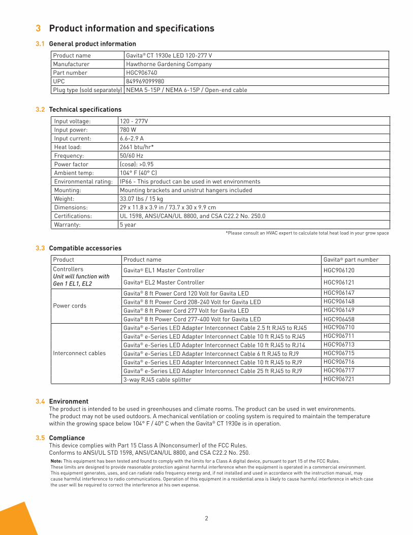
3 Product information and specifications3.1 General product information
Product name Gavita® CT 1930e LED 120-277 VManufacturer Hawthorne Gardening CompanyPart number HGC906740UPC 849969099980Plug type (sold separately) NEMA 5-15P / NEMA 6-15P / Open-end cable
3.2 Technical specificationsInput voltage: 120 - 277VInput power: 780 WInput current: 6.6-2.9 AHeat load: 2661 btu/hr*Frequency: 50/60 Hz Power factor (cosø): >0.95Ambient temp: 104° F (40° C)Environmental rating: IP66 - This product can be used in wet environmentsMounting: Mounting brackets and unistrut hangers includedWeight: 33.07 lbs / 15 kgDimensions: 29 x 11.8 x 3.9 in / 73.7 x 30 x 9.9 cmCertifications: UL 1598, ANSI/CAN/UL 8800, and CSA C22.2 No. 250.0Warranty: 5 year
3.3 Compatible accessoriesProduct Product name Gavita® part numberControllersUnit will function withGen 1 EL1, EL2
Gavita® EL1 Master Controller HGC906120
Gavita® EL2 Master Controller HGC906121
Power cords
Gavita® 8 ft Power Cord 120 Volt for Gavita LED HGC906147Gavita® 8 ft Power Cord 208-240 Volt for Gavita LED HGC906148Gavita® 8 ft Power Cord 277 Volt for Gavita LED HGC906149Gavita® 8 ft Power Cord 277-400 Volt for Gavita LED HGC906458
Interconnect cables
Gavita® e-Series LED Adapter Interconnect Cable 2.5 ft RJ45 to RJ45 HGC906710Gavita® e-Series LED Adapter Interconnect Cable 10 ft RJ45 to RJ45 HGC906711Gavita® e-Series LED Adapter Interconnect Cable 10 ft RJ45 to RJ14 HGC906713Gavita® e-Series LED Adapter Interconnect Cable 6 ft RJ45 to RJ9 HGC906715Gavita® e-Series LED Adapter Interconnect Cable 10 ft RJ45 to RJ9 HGC906716Gavita® e-Series LED Adapter Interconnect Cable 25 ft RJ45 to RJ9 HGC9067173-way RJ45 cable splitter HGC906721
3.4 EnvironmentThe product is intended to be used in greenhouses and climate rooms. The product can be used in wet environments. The product may not be used outdoors. A mechanical ventilation or cooling system is required to maintain the temperaturewithin the growing space below 104° F / 40° C when the Gavita® CT 1930e is in operation.
3.5 ComplianceThis device complies with Part 15 Class A (Nonconsumer) of the FCC Rules.Conforms to ANSI/UL STD 1598, ANSI/CAN/UL 8800, and CSA C22.2 No. 250.
*Please consult an HVAC expert to calculate total heat load in your grow space
Note: This equipment has been tested and found to comply with the limits for a Class A digital device, pursuant to part 15 of the FCC Rules. These limits are designed to provide reasonable protection against harmful interference when the equipment is operated in a commercial environment. This equipment generates, uses, and can radiate radio frequency energy and, if not installed and used in accordance with the instruction manual, may cause harmful interference to radio communications. Operation of this equipment in a residential area is likely to cause harmful interference in which case the user will be required to correct the interference at his own expense.
3
4 Safety recommendations and warnings
Warning! Carefully read the warnings below before using or working with the product! • Always adhere to local rules and regulations when installing or using the LED fixture.• Do not open or disassemble the LED fixture; there are no serviceable parts inside. Opening or modifying the LED fixture
can be dangerous and will void the warranty. • This product may cause interference to radio equipment and should not be installed near maritime safety communications
equipment or other critical navigation or communication equipment operating between 0.45-30 MHz.• Do not use the LED fixture when either the LED fixture or its power cord are damaged. Replace the power cord only
with original, certified cords. • Modifications to the cords can lead to unwanted electromagnetic effects, which makes the product not comply with
legal requirements.• Do not expose the LED fixture to:
- (ambient) temperatures outside the specified range; - dust and contamination; - direct sunlight during use or HID light that could heat up the fixture.
• Always disconnect the LED fixture from mains before performing any maintenance. • Always allow for a cool-down period of at least 30 minutes before touching the LED. Touching the LED when the fixture is
lit or immediately afterward can result in severe burns! • Do not use the LED fixture near flammable, explosive or reactive substances. Do not use sulfur vaporizers. • The installation and use of the LED fixture is the responsibility of the end user. Incorrect use or installation can lead
to failure and damage to the LED fixture. Damage to the LED fixture and electronic circuitry as a result of incorrect installation and use voids the warranty.
• The minimum distance between adjacent lighting equipment is 4 inches (10.16 cm). The minimum distance between lighting equipment and combustible materials is 4 inches (10.16 cm).
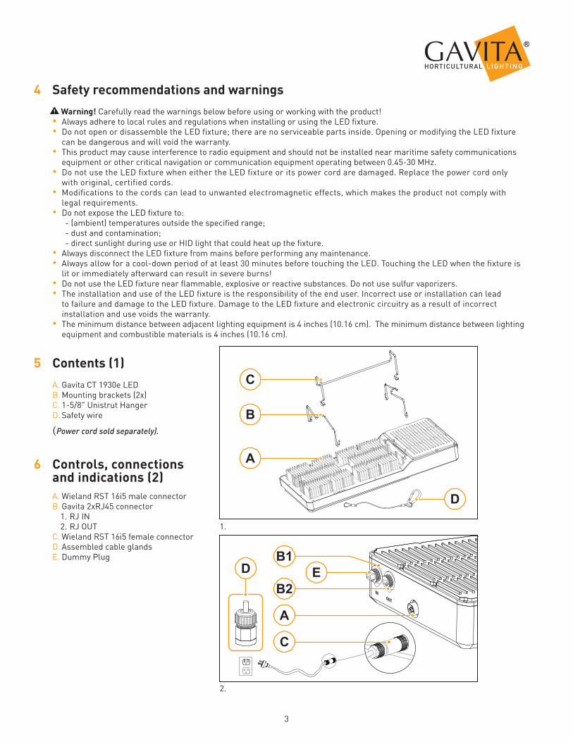
5 Contents (1)A. Gavita CT 1930e LEDB. Mounting brackets (2x)C. 1-5/8" Unistrut HangerD. Safety wire
(Power cord sold separately).
6 Controls, connections and indications (2)A. Wieland RST 16i5 male connectorB. Gavita 2xRJ45 connector
1. RJ IN2. RJ OUT
C. Wieland RST 16i5 female connectorD. Assembled cable glandsE. Dummy Plug
A
C
D EB1
B2
A
B
C
D
2.
1.

4
7 Installation Warning! Mounting and installation of the LED fixture may only be executed by certified service personnel, in accordance with applicable local laws and regulations. Warning! The installer is responsible for correct and safe installation. Warning! Ensure the local cabling can support the voltage and current requirements of the LED fixture. Warning! Avoid coiled cords and keep mains leads separated. This prevents electromagnetic interference. Warning! Do not connect or disconnect the LED fixture under load.
7.1 Installing the LED fixture
Warning! When mounting, attach the fixture to something that can support its entire weight.• Switch off main power.• Secure the hanging brackets to the fixture (fig. 3).• Hook the unistrut hanger onto the LED fixture hanging brackets (fig. 4). • Holding the LED fixture by the unistrut hanger with 2 hands, lift the fixture and place the hanger onto the unistrut as
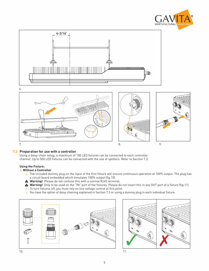
shown in the picture (fig. 5).• The center of the fixture is located 4-3/16" from the front of the unistrut hanging bracket (fig. 6).• Install safety wire (B) as shown in picture (fig. 7).• If a controller is not being used, make sure the dummy plug is inserted into the “IN” RJ45 communication port (fig. 8). • Plug the female main power into the LED fixture's male power input (fig. 9). Align the white arrow on the end of the
power connector with the "Closed Lock" symbol on the fixture. Press in until there is a “click” sound.
Make sure power cords:1. Are not concealed or extended through a wall, floor, ceiling, or other parts of the building structures.2. Are not located above a suspended ceiling or dropped ceiling.3. Are not permanently affixed to the building structure.4. Are routed so they are not subject to strain and are protected from physical damage.5. Are visible over their entire length.6. Are used within their rated ampacity as determined for the maximum temperature of the installed environment specified in the instructions.
4. 5.
3.
5
7.2 Preparation for use with a controllerUsing a daisy-chain setup, a maximum of 100 LED fixtures can be connected to each controller channel. Up to 500 LED fixtures can be connected with the use of splitters. Refer to Section 7.3.
Using the Fixture: 1. Without a Controller
a. The included dummy plug on the input of the first fixture will ensure continuous operation at 100% output. The plug has a circuit board embedded which simulates 100% output (fig.10).
Warning! Please do not confuse this with a normal RJ45 terminal. Warning! Only to be used on the “IN” port of the fixtures. Please do not insert this in any OUT port of a fixture (fig.11).
b. To turn fixtures off, you must rely on line voltage control at this point.c. You have the option of daisy chaining explained in Section 7.3 or using a dummy plug in each individual fixture.
4-3/16"
6.
8. 9. 7.
10. 11.
✓ ✗
6
13.
16. 17.
19.
18.
14. 15.
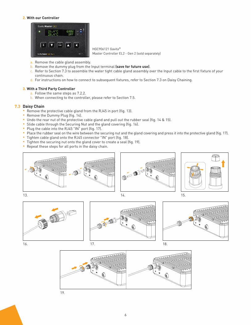
2. With our Controller
a. Remove the cable gland assembly.b. Remove the dummy plug from the Input terminal (save for future use).c. Refer to Section 7.3 to assemble the water tight cable gland assembly over the Input cable to the first fixture of your
continuous chain.d. For instructions on how to connect to subsequent fixtures, refer to Section 7.3 on Daisy Chaining.
3. With a Third Party Controllera. Follow the same steps as 7.2.2.b. When connecting to the controller, please refer to Section 7.5.
7.3 Daisy Chain• Remove the protective cable gland from the RJ45 in port (fig. 13).• Remove the Dummy Plug (fig. 14).• Undo the rear nut of the protective cable gland and pull out the rubber seal (fig. 14 & 15).• Slide cable through the Securing Nut and the gland covering (fig. 16).• Plug the cable into the RJ45 "IN" port (fig. 17).• Place the rubber seal on the wire between the securing nut and the gland covering and press it into the protective gland (fig. 17).• Tighten cable gland onto the RJ45 connector "IN" port (fig. 18).• Tighten the securing nut onto the gland cover to create a seal (fig. 19).• Repeat these steps for all ports in the daisy chain.
HGC906121 Gavita®
Master Controller EL2 - Gen 2 (sold separately)
7
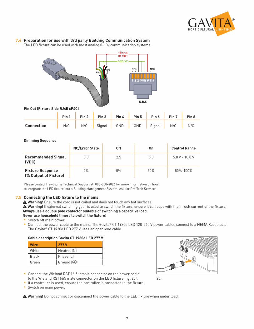
7.4 Preparation for use with 3rd party Building Communication SystemThe LED fixture can be used with most analog 0-10v communication systems.
Pin Out (Fixture Side RJ45 6P4C)
Pin 1 Pin 2 Pin 3 Pin 4 Pin 5 Pin 6 Pin 7 Pin 8
Connection N/C N/C Signal GND GND Signal N/C N/C
Dimming Sequence
NC/Error State Off On Control Range
Recommended Signal (VDC)
0.0 2.5 5.0 5.0 V - 10.0 V
Fixture Response (% Output of Fixture)
0% 0% 50% 50%-100%
Please contact Hawthorne Technical Support at: 888-808-4826 for more information on howto integrate the LED fixture into a Building Management System. Ask for Pro Tech Services.
7.5 Connecting the LED fixture to the mains Warning! Ensure the cord is not coiled and does not touch any hot surfaces. Warning! If external switching gear is used to switch the fixture, ensure it can cope with the inrush current of the fixture.
Always use a double pole contactor suitable of switching a capacitive load.Never use household timers to switch the fixture!• Switch off main power.• Connect the power cable to the mains. The Gavita® CT 1930e LED 120-240 V power cables connect to a NEMA Receptacle.
The Gavita® CT 1930e LED 277 V uses an open-end cable.
Cable description Gavita CT 1930e LED 277 V:
Wire 277 VWhite Neutral (N)Black Phase (L)Green Ground ( )
• Connect the Wieland RST 16i5 female connector on the power cable to the Wieland RST16i5 male connector on the LED fixture (fig. 20). • If a controller is used, ensure the controller is connected to the fixture.• Switch on main power.
Warning! Do not connect or disconnect the power cable to the LED fixture when under load.
+Signal(0-10V)
GND/VE
N/CN/CN/C
N/C
1 2 3 4 5 6 7 8
RJ45
20.
8 Inspection, maintenance and repair Warning! Disconnect the LED fixture from mains before performing any maintenance or repairs. Warning! Do not connect or disconnect the LED fixture under load. Warning! Do not open or disassemble the LED fixture; there are no serviceable parts inside. Opening the LED fixture can be dangerous and will void the warranty. Warning! Always allow for a cool-down period of at least 30 minutes before touching the LED. Caution! Do not clean the LED fixture with detergents, abrasives or other aggressive substances.
• Regularly check the LED fixture for dust or dirt buildup. Clean if necessary. Contamination may cause overheating and decreased performance. Clean the outside of the LED fixture using a dry or damp cloth.
• Regularly check the cables of the LED fixture to ensure it is undamaged.
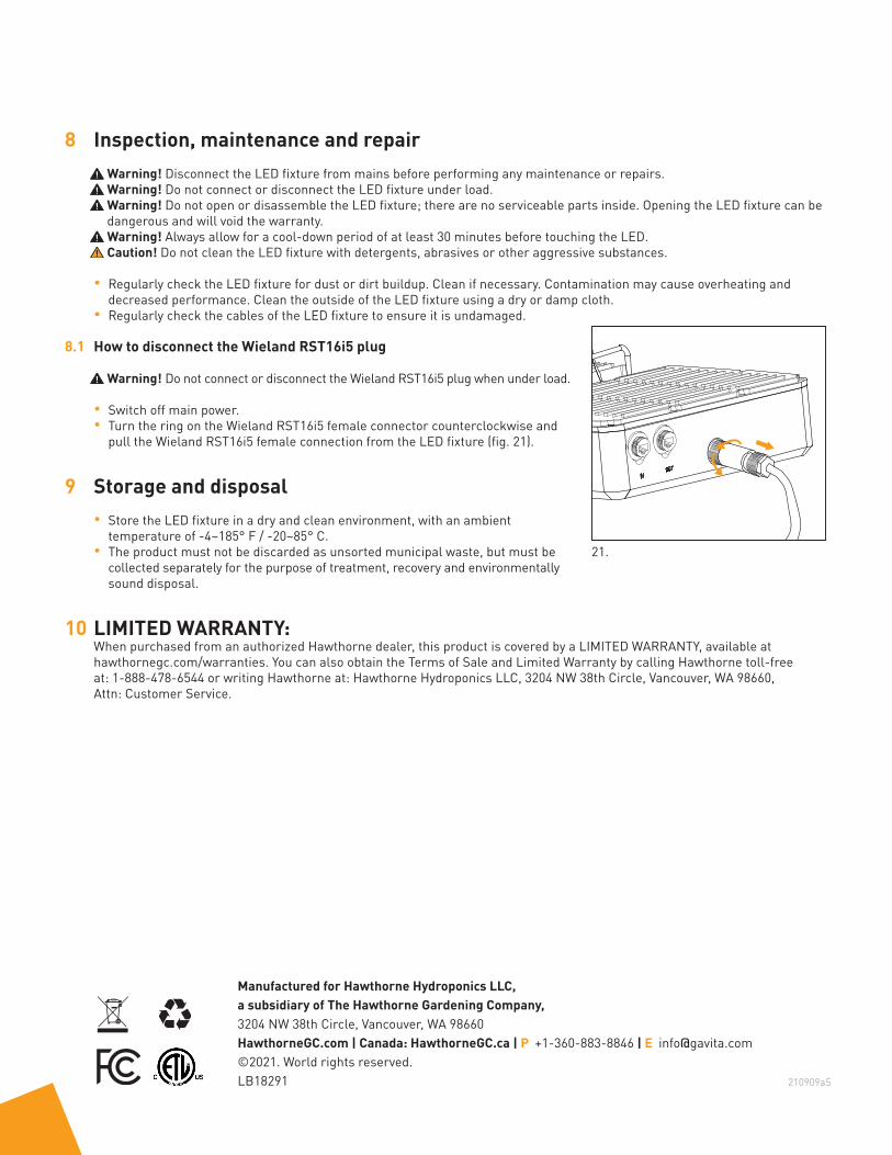
8.1 How to disconnect the Wieland RST16i5 plug
Warning! Do not connect or disconnect the Wieland RST16i5 plug when under load.
• Switch off main power.• Turn the ring on the Wieland RST16i5 female connector counterclockwise and
pull the Wieland RST16i5 female connection from the LED fixture (fig. 21).
9 Storage and disposal• Store the LED fixture in a dry and clean environment, with an ambient
temperature of -4~185° F / -20~85° C.• The product must not be discarded as unsorted municipal waste, but must be
collected separately for the purpose of treatment, recovery and environmentally sound disposal.
10 LIMITED WARRANTY: When purchased from an authorized Hawthorne dealer, this product is covered by a LIMITED WARRANTY, available at hawthornegc.com/warranties. You can also obtain the Terms of Sale and Limited Warranty by calling Hawthorne toll-freeat: 1-888-478-6544 or writing Hawthorne at: Hawthorne Hydroponics LLC, 3204 NW 38th Circle, Vancouver, WA 98660, Attn: Customer Service.
210909aS
Manufactured for Hawthorne Hydroponics LLC,a subsidiary of The Hawthorne Gardening Company,3204 NW 38th Circle, Vancouver, WA 98660HawthorneGC.com | Canada: HawthorneGC.ca | P +1-360-883-8846 | E [email protected]©2021. World rights reserved.LB18291
21.