gas technology summer 2011 issue
TRANSCRIPT

Make Full use oF Your energYWith Industrial Turbines
suMMer /11 voluMe 24 / I ssue 2
The source For energY soluTIons WWW.energYsoluTIonscenTer.org

on the cover
An industrial turbine in combined
heat and power service at a plastics
manufacturing plant in Rhode Island.
Photo courtesy Solar Turbines.
Gas Technology is a trademark of Energy Solutions Center Inc. and is published in cooperation with CFE Media, LLC.
Gas Technology is an educational supplement from: Energy Solutions Center Inc. 400 N. Capitol St., N.W. Washington, DC 20001 T (202) 824-7150 www.energysolutionscenter.org
David Weiss, Executive DirectorJake Delwiche Contributing EditorComments may be directed to: Gas Technology Editor Plant Engineering Magazine 1111 W. 22nd Street, Ste. 250 Oak Brook, IL 60523 T (630) 571-4070
Printed in the USA
energy solutions center websites
www.aircompressor.org
www.cleanboiler.org
www.energysolutionscenter.org
www.naturalgasefficiency.org
www.gasairconditioning.org
www.poweronsite.org
www.foodtechinfo.com
A6 Natural Gas-Powered Trucking. More engine and vehicle options and a growing CNG distribution network support sustainable growth in natural gas fueled trucks.
A8 Big Fans Make a Big Difference. HVLS fans have the ability to keep the workplace cool by creating continuous high-volume air movement. What’s more, they can reduce heating costs by de-stratifying air.
A10 Floor Heating Finds New Friends. Radiant floor heating systems are ideal for manufacturing and warehouse areas by supplying heat at the working level.
A12 Vertical Tubeless Boilers. An innovative design for package boilers offers high efficiency, rapid response to demand, and a small footprint to add capacity to a crowded boiler room.
inside
A3Industrial Turbines Spell Opportunity. Owners find industrial turbines an ideal way to improve energy utilization efficiency, plus gain energy supply reliability.

Gas Turbines Spell Opportunity for Industry
Two Solar Titan 130 gas turbine generator sets in cogeneration application at a paper processing plant in Connecticut. Photo courtesy Solar Turbines.
Getting Much More for Your Energy Dollar
Today many indusTrial energy users understand
the opportunity implicit in cogeneration. The idea is that all
thermal methods of electric generation also produce waste
heat – a lot of it. Combined heat and power (CHP) installations
capture that heat and use it as a valuable byproduct rather than
rejecting it as waste. Gas turbine CHP plants are an increasingly
popular way of meeting the electrical needs of industrial and
institutional facilities, as well as their requirements for steam or
hot water.
Not a New TechnologyGas turbines in various sizes have been available for more than
50 years. Fuels can include oil or industrial byproduct gases,
however most installations use natural gas. Units can be used for
direct-drive applications, such as for pipeline gas compression,
but the most common usage is for electric generation. Within
these systems, a portion of the mechanical energy generated by
combustion is used in the combustion air compressor section of
the turbine, and the remainder of the rotational energy spins a
generator for electric generation.
With all gas turbines, a significant amount of energy is produced
in the form of combustion waste heat. In typical electric utility
gas turbine generation installations, this waste heat is sometimes
simply exhausted. These are called single cycle installations. In
other utility installations the heat is used to fire a heat recovery
steam generator (HRSG) to generate steam for additional electric
generation. These heat recovery combination systems are called
combined-cycle plants.
Utilities Use as Peaking GenerationUtilities often use gas turbines for peaking generation or even for
longer duty operation when they are combined-cycle plants. They
are attractive to utilities because they are largely factory assembled
and can be erected in a matter of weeks or months rather than
requiring years as with more traditional forms of generation.
Further, they can be started quickly and brought on line, often in
less than one minute.
Increasingly, owners of industrial and institutional facilities are
also looking at owning gas turbine equipment for on-site electric
generation, and they are more likely to take full advantage of
w w w. e n e r g y S o l u t i o n S c e n t e r . o r g g a s t e c h n o l o g y / S u M M e r 1 1 A 3

A 4 g a s t e c h n o l o g y / S u M M e r 1 1 w w w. e n e r g y S o l u t i o n S c e n t e r . o r g
Control area for three gas turbine generator sets in a combined heat and power application at a university in Connecticut. Photo courtesy Solar Turbines.
A recuperated gas turbine providing heating, cooling, and power at hospital in Texas. Photo courtesy Solar Turbines.
the byproduct heat output. These are
called combined heat and power (CHP)
installations.
Wide Range of Potential UsesExamples of facilities that might be able
to effectively use both the electrical and
thermal outputs of a gas turbine are large
hotels, resorts, prisons, universities, laun-
dries, food processing plants, pulp and
paper mills, and other industries that use
either steam or hot water in significant
quantities.
Another potential application is using
the heat to supply absorption chillers to
provide chilled water for comfort cooling
or process applications. In addition to the
energy-saving potential of cogeneration
gas turbines, they also provide energy
system security by having an onsite source
of electric power in the event of a utility
service outage.
Higher-Grade Byproduct HeatTypically, gas turbines generate higher-
temperature waste heat than engine-
powered CHP systems, making high quality
steam generation possible and broadening
the range of potential applications.
Although the electric generation
efficiency of gas turbines has been steadily
improving, the proportion of byproduct
heat is still very significant. An example
might be a natural gas-fired turbine rated
at 5 MWe. The turbine exhaust can be
diverted through a steam generator and
can produce 23,000 lbs. of 150 psig steam
per hour, enough to meet the heating and
hot water needs of a good-sized industrial
or university campus.
Several manufacturers, including Solar,
Kawasaki, Opra, and Dresser-Rand, offer
gas turbine electrical generation packages
that range from 500 kWe to 10 MWe and
even larger — sizes ideal for many insti-
tutional and industrial applications. Units
much larger than this and microturbines
rated below 500 kWe are also available.
Solar Offers Range of UnitsChris Lyons from Solar Turbines was re-
cently a presenter at a Technology & Mar-
ket Assessment Forum, sponsored by the
Energy Solutions Center. Solar is a major
manufacturer of gas turbine-generators for
the industrial market and offers 11 models
ranging in size from 1.2 to 21.7 MWe in
capacity. He explains that the generation
efficiency of gas turbines is generally ex-

m o r e
i n f oDRESSER-RAND GAS TURBINES www.dresser-rand.com/products/turbo/gasturbine
ENERGY SOLUTIONS CENTER DISTRIBUTED GENERATION www.poweronsite.org
KAWASAKI GAS TURBINES – AMERICAS www.kawasakigasturbines.com
OPRA TURBINES www.opra.no/en
SOLAR TURBINES mysolar.cat.com
w w w. e n e r g y S o l u t i o n S c e n t e r . o r g g a s t e c h n o l o g y / S u M M e r 1 1 A 5
Diagram illustrates energy flows through a CHP application with a gas turbine. Illustration courtesy Solar Turbines.
Air inleT FilTer/SilenCer
generATorgAS Turbine
exhAuST buPASS SilenCer
DiverTer vAlve
burner
heAT reCovery STeAm generATor (hrSg)
exhAuST SilenCer
pressed as their “heat rate”, the required
number of Btus needed to generate one
kWh. In the Solar family of gas turbines for
electric generation in the industrial range,
heat rates range from 8,774 to 14,025.
Generally speaking, the larger turbine
packages have lower heat rates, meaning
they are more efficient.
Lyons points out that Solar has a world-
wide presence in both the oil and gas in-
dustry and the power generation markets.
“We have 43 service centers, including 13
overhaul centers and 19 parts centers. We
have over 13,800 turbines installed in 98
countries.” Solar is a division of Caterpillar.
Potential Benefits to EconomyLyons stresses the potential benefits of
CHP. “DOE has set the goal of doubling
the use of CHP in the U.S. In this way, an
additional 25 million tons of CO2 could be
avoided, grid reliability could be increased,
line losses could be reduced by 5-20%
and the utility investment to meet power
production costs could be reduced by $136
billion. The advantages are enormous.”
Obviously, the more hours an industrial
owner plans to operate a CHP plant, the
more priority should placed on a low heat
rate. However, most gas turbines are most
efficient near their rated capacity. For this
reason, your system efficiency may be
highest if you have multiple smaller units,
allowing you to operate several units closer
to their optimum heat rate.
Sizing to Thermal DemandIn order to maximize CHP energy effi-
ciency, owners generally size the system
to match their need for process or com-
fort heat and cooling, and purchase the
necessary additional electric energy. In
some situations where there is high heat
energy utilization, operators may be able
to generate more electric power that can
be used on site. In many such situations,
the remaining electric energy can be sold
back to the electric utility.
The advantages of CHP are becoming
understood. In another recent presenta-
tion at a Technology & Market Assess-
ment Forum, Kawasaki spokesman Mario
DeRobertis noted that the largest market
share is in gas turbine units 10 MW and below
— the industrial market. He pointed out that
Kawasaki has sold over 8,000 units —
mostly into CHP projects. He indicated that
owners typically experience thermodynam-
ic efficiencies from 75% to 82%. Kawasaki
offers base-load units sized at 600 kW, and
1.5, 1.7, 3.0, 5.5, 8.0 and 17.9 MW.
Documented Installation Shows BenefitsA well-documented installation of CHP in
an industrial facility was a DOE project at
a Frito-Lay food processing plant in Kill-
ingly, Connecticut. DOE notes that food
processing is a high-growth industry with
tremendous potential for CHP because of
its need for significant amounts of both
electrical and thermal energy. In this proj-
ect, a 4.6 MW Solar Centaur 50 combus-
tion turbine was installed, combined with
a Rentech heat recovery steam generator.
The system was commissioned in April
2009 and one year of data collection was
completed in May 2010 with funding from
DOE and a consortium of Energy Solution
Center utility members.
A recent DOE report states, “Operating
data show the CHP system providing over
90% of the electrical demand and about
80% of the steam load for the facility. The
performance of the CHP system has been
excellent, with virtually no interruptions
in operation and an overall CHP efficiency
of 70%.” On two occasions during the one
year data collection period, the CHP sys-
tem helped the plant maintain operations
during extended periods of grid power
outages. DOE indicates “This information
will be valuable for understanding the role
of CHP in providing economic and reliable
energy services for small- and medium-
sized industrial facilities.”
Time to Take a Hard LookIndustrial and institutional energy users
that have both high electrical and thermal
energy requirements need to take a hard
look at gas turbine packages complete with
heat recovery — CHP. The technology is
mature and reliable. Natural gas prices
are low and promise to remain attractive
into the future. The door of opportunity
is open. GT

Powered by PersisTenTly high diesel and gasoline fuel
prices, and encouraged by state and federal incentive programs for
alternate fuel vehicles, the use of natural gas as a trucking fuel con-
tinues to find converts in the U.S. and Canada. Many of the appli-
cations are on vehicles that are used during the day and returned
to a base station at night, making refueling easier. Both public and
private refueling stations are becoming more abundant.
Fueling Stations Critical ComponentsOne of the leading industry organizations supporting natural
gas fueling is the Natural Gas Vehicle Institute (NGVi). This
organization offers guidance and training for fleet operators who
are contemplating converting to or expanding natural gas-powered
fleet vehicles. NGVi CEO Leo Thomason was a recent presenter on
a panel discussion on natural gas vehicles at a Technology Market
Assessment Forum sponsored by the Energy Solutions Center. In
his presentation, Thomason stressed the key role played by fueling
stations for commercial and industrial natural gas users.
He explained that there are four basic types of natural gas
fuelling stations. The simplest is time-fill fueling, where a fleet
of vehicles at a central garage can be filled during nighttime or
other inactive hours. This is ideal for fleets of vehicles that are at a
central location for 6-8 hours and can operate all day on a single
fill. Examples are school buses, transit buses, delivery vans, refuse
trucks and ready-mix cement vehicles.
Fast-Fill Stations for Random FuelingThe opposite is fast-fill, which is used for vehicles that need to be
quickly refueled at random hours through the day. A third type
is combination time-fill and fast-fill, which is suitable for a mix of
vehicle types and for those that require refueling at random times.
The fourth type is buffer fast-fill, used where large numbers of
vehicles need to be refueled consecutively - for example, fleets of
transit buses. A buffer tank allows quick consecutive refilling.
Thomason explains that the cost of the refueling station varies
with the type of capability, and can range from several thousand
dollars for a small timed-fill system for a single vehicle to several
million dollars for a fleet refueling station for 200 transit buses. He
notes that a public-access fast-fill station could run from $400,000
to $500,000. Owners need to consider this expense in evaluat-
ing the feasibility of going to a natural gas fleet. He indicates that
there continues to be an active “buildout” of natural gas fueling
infrastructure in North America.
Infrastructure Continues to ExpandThe natural gas fueling infrastructure has been steadily expand-
New Markets, New Opportunities
A 6 g a s t e c h n o l o g y / S u M M e r 1 1 w w w. e n e r g y S o l u t i o n S c e n t e r . o r g
TruckingNatural Gas-Powered
ing beyond California in recent years. Ac-
cording to Thomason, a good part of the
expansion has come from the activities
of Clean Energy of Seal Beach, Califor-
nia. This company is the largest retailer
of natural gas as a transportation fuel in
the U.S. Clean Energy has built and oper-
ates public-access CNG fueling stations in
Arizona, Colorado, Nevada, New Mexico,
New York, Texas, Wyoming, Oklahoma
and Georgia.
Thomason adds that many natural gas
utilities have and continue to operate
public-access fueling stations within their
areas. These include DTE Energy, Avista
Utilities, Alabama Gas, Atlanta Gas Light,
National Grid, Questar Utilities, Piedmont
Natural Gas and others.
Manufacturer Credits Offset Engine ExpenseAccording to Andy Douglas, National Sales
Manager, Specialty Markets for Kenworth
Truck Company, there continue to be price
credits for owners who choose to operate
CNG trucks. A CNG-powered refuse truck
or cement truck would receive a $10,000
credit for not having the SCR after-exhaust
treatment system required for a diesel-pow-
ered version of the same truck. This would
offset the $10,000 premium for the Cum-
mins-Westport CNG engine for the truck.
According to Thomason, there continue
to be new natural gas engine conversion
companies entering the market. Currently
there are five companies that manufacture
EPA/CARB certified conversion systems for
gasoline-powered vehicles in the U.S.
Rich Kolodziej is the President of
NGVAmerica, an organization dedicated
to the promotion of the use of natural
gas vehicles in the U.S. He points out that
earlier arguments that the U.S. lacked a
sufficient long-term supply of natural
gas have been demolished. He states,
“Technological advances such as deep
drilling, horizontal drilling and fracturing
have made previous uneconomic gas play
(like shale gas) quite economic. This has in
turn resulted in estimates of economically
recoverable gas at (or over) 100 years.”
Current NGV Legislation ImportantKolodziej stresses the importance of legis-
lation such as the currently pending NAT
GAS Act (HR 1380) currently under con-
sideration in the House of Representatives.
A companion Senate bill will be intro-
duced this summer. The bill would provide
a number of financial incentives to fleets
and consumers who buy natural gas vehi-
cles, and to fueling station operators who
install natural gas fueling equipment. He is
hopeful the legislation will be signed into
law in 2011 and will continue and enhance
previous federal incentive programs.
Kolodziej also points out that there is
incredible activity at the state level pro-
moting NGVs. Currently 255 bills are
under consideration in state legislatures
that would provide a variety of incentives
or supports for NGV activity. Kolodziej
notes, “Because of its special environ-
mental problems and concerns, Utah has
been in the vanguard of providing incen-
tives for and otherwise promoting NGVs.
But the rest of the country is catching up
fast. Utah has been a strong NGV promot-
er for a number of years and Oklahoma,
Louisiana and Texas have recently en-
acted or expanded incentives for NGVs.”
Fuel Price Advantage ContinuesSince 2005 the energy market has shown
significant price spreads between the deliv-
ered fuel cost of diesel fuel and natural gas.
Natural gas at $6/mmBtu is approximately
equivalent to crude oil at $45/barrel, a price
we haven’t enjoyed for a long time.
According to recent studies, the next
three to five years may show increasing
price spreads as a result of strong domestic
production of natural gas from conven-
tional and shale gas sources, and continu-
ing upward pressure on petroleum prices
because of global oil demand and geopo-
litical uncertainty. At the current time, up
to 98% of the natural gas used in the U.S.
and Canada is from U.S. and Canadian
sources. This gives additional security for
fleet fuel supplies.
Things Lining Up FavorablyThe future looks bright for the NGV in-
dustry. Rich Kolodziej says, “NGVs have
always had public policy benefits. Now
that we have the natural gas supply, we
have the vehicles, we have public policy
support and we have the economics.” He
notes that the number of NGVs worldwide
has grown from 3.8 million in 2003 to
13.2 million today. While many of those
are light-duty vehicles in Pakistan, India
and Iran, the growth in North America
has been largely heavy-duty trucks and
buses. This truly is a growth industry, and
one that promises rewards for early adap-
tors. Now may be your time to take ad-
vantage of this trend. GT
w w w. e n e r g y S o l u t i o n S c e n t e r . o r g g a s t e c h n o l o g y / S u M M e r 1 1 A 7
m o r e
i n f oDOE NATURAL GAS VEHICLE INFORMATION www.afdc.energy.gov/afdc/vehicles/natural_gas.html
ENERGY SOLUTIONS CENTER NGV WORKGROUP www.energysolutionscenter.org/consortia/ngv_workgroup.aspx
NATURAL GAS VEHICLES FOR AMERICA (NGVAMERICA) www.ngvc.org
NATURAL GAS VEHICLE INSTITUTE (NGVI) www.ngvi.com
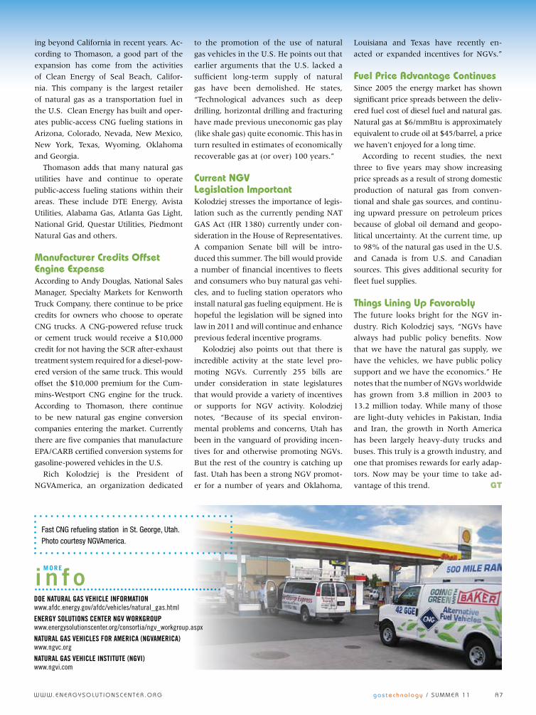
Fast CNG refueling station in St. George, Utah. Photo courtesy NGVAmerica.

Big Fans Big Difference
HVLS Fans Cool in Summer, Distribute Heat in Winter
Make a
A 8 g a s t e c h n o l o g y / S u M M e r 1 1 w w w. e n e r g y S o l u t i o n S c e n t e r . o r g
wiThouT Taking anyThing away
from air conditioning, it is not the only
option for comfort cooling. What’s more,
it doesn’t do anything for your building
during the heating season. An option that
is receiving increasing attention is high-
volume low-speed (HVLS) ceiling fans.
These not only provide energy-efficient
comfort cooling in the summer, but they
can also improve the efficiency of your
heating system in winter.
Comfort Level Up DramaticallyDon’t confuse these with the small ceiling
paddle fans in your living room, kitchen or
bedroom. These are BIG fans, with diame-
ters up to 24 feet. They rotate slowly, but be-
cause of their size can move a lot of air. And
air movement is the key to summer comfort
for many spaces. By moving air over build-
ing occupants, evaporative cooling increases,
improving comfort levels. According to some
experts, the right HVLS system can reduce
the perception of heat by 8 to 16 degrees.
Many commercial and industrial
building have high ceilings and require
higher overhead clearances. You need a
big fan to move the necessary volume of air
to give effective cooling. That’s why HVLS
fans have large diameters and because of
their blade length, can operate efficiently
at relatively low rotational speeds.
Units Designed for Large SpacesOne of the industry leaders in HVLS fans is
the humorously-named Big Ass Fan Co. of
Lexington, Kentucky. The company offers
its Powerfoil line of fans for the indus-
trial building market in sizes ranging from
8 to 24 feet. These fans feature a sealed
and nitrogen-bathed gear reduction drive,
with prewired on-board electronic con-
trols. The design of the ten airfoil blades
maximizes efficient air movement and
minimizes acoustic levels to nearly unde-
tectable levels. A winglet at the tip of each
blade eliminates efficiency-robbing vortex
formation. Big Ass Fan Co. also offer its Isis
line of smaller, lighter fans in diameters of
eight or ten feet for ceilings as low as 12
feet as in smaller commercial and indus-
trial areas.
According to company spokesperson
Katie Hunt, increasing number of owners
are discovering the benefits of HVLS fans.
“Given the vast space within manufacur-
ing and warehouse facilities, these fans help
eliminate cold and hot spots often prevalent
with small, high velocity fans. During the
winter, the fans run at a much slower speed
to turn the air over at least once per hour to
destratify the space and keep the tempera-
ture even, which can significantly reduce
heating bills. The slow speed also prevents
occupants from feeling a chilly draft.”
Added Benefits in Heating SeasonAs Hunter notes, HVLS fans also bring
comfort benefits during the heating sea-
son. In many cases the heat in these high
spaces stratifies and it can be as much as
20 degrees F warmer at the ceiling than at
Left: Large space with high ceilings are the ideal location for HVLS fans.
Right: HVLS fans not only improve comfort by generating air movement during hot weather, but can help reduce heating costs by de-stratifying air during the heating season. Photos courtesy Big Ass Fan Company
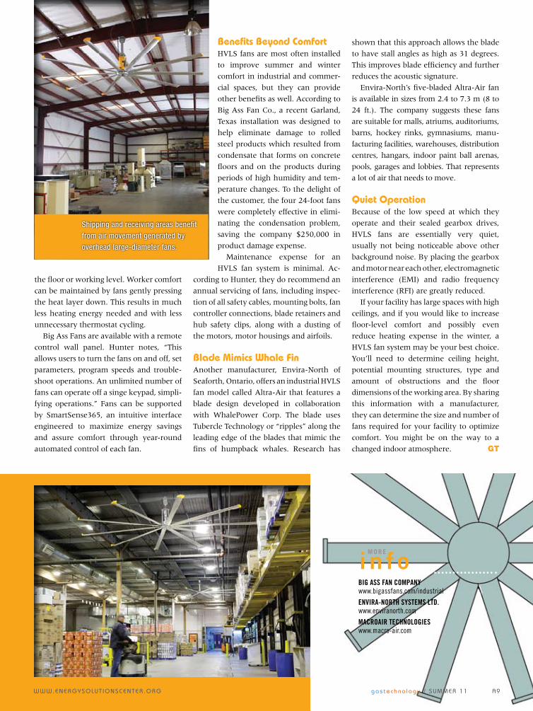
Shipping and receiving areas benefit from air movement generated by overhead large-diameter fans.
m o r e
i n f oBIG ASS FAN COMPANY www.bigassfans.com/industrial
ENVIRA-NORTH SYSTEMS LTD. www.enviranorth.com
MACROAIR TECHNOLOGIES www.macro-air.com
the floor or working level. Worker comfort
can be maintained by fans gently pressing
the heat layer down. This results in much
less heating energy needed and with less
unnecessary thermostat cycling.
Big Ass Fans are available with a remote
control wall panel. Hunter notes, “This
allows users to turn the fans on and off, set
parameters, program speeds and trouble-
shoot operations. An unlimited number of
fans can operate off a singe keypad, simpli-
fying operations.” Fans can be supported
by SmartSense365, an intuitive interface
engineered to maximize energy savings
and assure comfort through year-round
automated control of each fan.
Benefits Beyond ComfortHVLS fans are most often installed
to improve summer and winter
comfort in industrial and commer-
cial spaces, but they can provide
other benefits as well. According to
Big Ass Fan Co., a recent Garland,
Texas installation was designed to
help eliminate damage to rolled
steel products which resulted from
condensate that forms on concrete
floors and on the products during
periods of high humidity and tem-
perature changes. To the delight of
the customer, the four 24-foot fans
were completely effective in elimi-
nating the condensation problem,
saving the company $250,000 in
product damage expense.
Maintenance expense for an
HVLS fan system is minimal. Ac-
cording to Hunter, they do recommend an
annual servicing of fans, including inspec-
tion of all safety cables, mounting bolts, fan
controller connections, blade retainers and
hub safety clips, along with a dusting of
the motors, motor housings and airfoils.
Blade Mimics Whale FinAnother manufacturer, Envira-North of
Seaforth, Ontario, offers an industrial HVLS
fan model called Altra-Air that features a
blade design developed in collaboration
with WhalePower Corp. The blade uses
Tubercle Technology or “ripples” along the
leading edge of the blades that mimic the
fins of humpback whales. Research has
shown that this approach allows the blade
to have stall angles as high as 31 degrees.
This improves blade efficiency and further
reduces the acoustic signature.
Envira-North’s five-bladed Altra-Air fan
is available in sizes from 2.4 to 7.3 m (8 to
24 ft.). The company suggests these fans
are suitable for malls, atriums, auditoriums,
barns, hockey rinks, gymnasiums, manu-
facturing facilities, warehouses, distribution
centres, hangars, indoor paint ball arenas,
pools, garages and lobbies. That represents
a lot of air that needs to move.
Quiet OperationBecause of the low speed at which they
operate and their sealed gearbox drives,
HVLS fans are essentially very quiet,
usually not being noticeable above other
background noise. By placing the gearbox
and motor near each other, electromagnetic
interference (EMI) and radio frequency
interference (RFI) are greatly reduced.
If your facility has large spaces with high
ceilings, and if you would like to increase
floor-level comfort and possibly even
reduce heating expense in the winter, a
HVLS fan system may be your best choice.
You’ll need to determine ceiling height,
potential mounting structures, type and
amount of obstructions and the floor
dimensions of the working area. By sharing
this information with a manufacturer,
they can determine the size and number of
fans required for your facility to optimize
comfort. You might be on the way to a
changed indoor atmosphere. GT
w w w. e n e r g y S o l u t i o n S c e n t e r . o r g g a s t e c h n o l o g y / S u M M e r 1 1 A 9
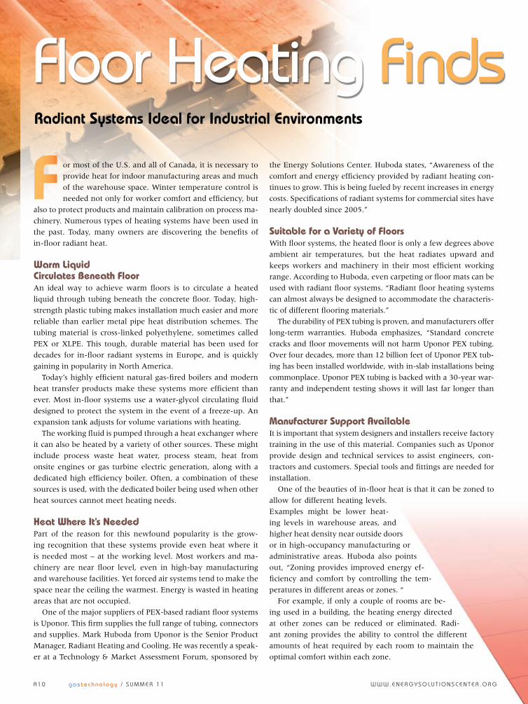
Floor Heating Finds new FriendsRadiant Systems Ideal for Industrial Environments
or most of the U.S. and all of Canada, it is necessary to
provide heat for indoor manufacturing areas and much
of the warehouse space. Winter temperature control is
needed not only for worker comfort and efficiency, but
also to protect products and maintain calibration on process ma-
chinery. Numerous types of heating systems have been used in
the past. Today, many owners are discovering the benefits of
in-floor radiant heat.
Warm Liquid Circulates Beneath FloorAn ideal way to achieve warm floors is to circulate a heated
liquid through tubing beneath the concrete floor. Today, high-
strength plastic tubing makes installation much easier and more
reliable than earlier metal pipe heat distribution schemes. The
tubing material is cross-linked polyethylene, sometimes called
PEX or XLPE. This tough, durable material has been used for
decades for in-floor radiant systems in Europe, and is quickly
gaining in popularity in North America.
Today’s highly efficient natural gas-fired boilers and modern
heat transfer products make these systems more efficient than
ever. Most in-floor systems use a water-glycol circulating fluid
designed to protect the system in the event of a freeze-up. An
expansion tank adjusts for volume variations with heating.
The working fluid is pumped through a heat exchanger where
it can also be heated by a variety of other sources. These might
include process waste heat water, process steam, heat from
onsite engines or gas turbine electric generation, along with a
dedicated high efficiency boiler. Often, a combination of these
sources is used, with the dedicated boiler being used when other
heat sources cannot meet heating needs.
Heat Where It’s NeededPart of the reason for this newfound popularity is the grow-
ing recognition that these systems provide even heat where it
is needed most – at the working level. Most workers and ma-
chinery are near floor level, even in high-bay manufacturing
and warehouse facilities. Yet forced air systems tend to make the
space near the ceiling the warmest. Energy is wasted in heating
areas that are not occupied.
One of the major suppliers of PEX-based radiant floor systems
is Uponor. This firm supplies the full range of tubing, connectors
and supplies. Mark Huboda from Uponor is the Senior Product
Manager, Radiant Heating and Cooling. He was recently a speak-
er at a Technology & Market Assessment Forum, sponsored by
the Energy Solutions Center. Huboda states, “Awareness of the
comfort and energy efficiency provided by radiant heating con-
tinues to grow. This is being fueled by recent increases in energy
costs. Specifications of radiant systems for commercial sites have
nearly doubled since 2005.”
Suitable for a Variety of FloorsWith floor systems, the heated floor is only a few degrees above
ambient air temperatures, but the heat radiates upward and
keeps workers and machinery in their most efficient working
range. According to Huboda, even carpeting or floor mats can be
used with radiant floor systems. “Radiant floor heating systems
can almost always be designed to accommodate the characteris-
tic of different flooring materials.”
The durability of PEX tubing is proven, and manufacturers offer
long-term warranties. Huboda emphasizes, “Standard concrete
cracks and floor movements will not harm Uponor PEX tubing.
Over four decades, more than 12 billion feet of Uponor PEX tub-
ing has been installed worldwide, with in-slab installations being
commonplace. Uponor PEX tubing is backed with a 30-year war-
ranty and independent testing shows it will last far longer than
that.”
Manufacturer Support AvailableIt is important that system designers and installers receive factory
training in the use of this material. Companies such as Uponor
provide design and technical services to assist engineers, con-
tractors and customers. Special tools and fittings are needed for
installation.
One of the beauties of in-floor heat is that it can be zoned to
allow for different heating levels.
Examples might be lower heat-
ing levels in warehouse areas, and
higher heat density near outside doors
or in high-occupancy manufacturing or
administrative areas. Huboda also points
out, “Zoning provides improved energy ef-
ficiency and comfort by controlling the tem-
peratures in different areas or zones. “
For example, if only a couple of rooms are be-
ing used in a building, the heating energy directed
at other zones can be reduced or eliminated. Radi-
ant zoning provides the ability to control the different
amounts of heat required by each room to maintain the
optimal comfort within each zone.
A 1 0 g a s t e c h n o l o g y / S u M M e r 1 1 w w w. e n e r g y S o l u t i o n S c e n t e r . o r g
F

Floor Heating Finds new FriendsZoning Provides Operating FlexibilityHeat output can be controlled both by the spacing of heating
tubes and thermostatic control of heat outputs by zone. Zone-
by-zone thermostat control is especially useful in manufacturing
areas that are frequently re-arranged, or where there are sea-
sonal variations in floor usage. Manufacturers such as Uponor
offer a variety of thermostats with different features to accom-
modate a wide variety of applications and user preferences.
An example of a successful installation of radiant flooring is
in a 50,000 square foot distribution center operated by Henri
Studio, a designer and manufacturer of case stone fountains and
statuary in Wauconda, Illinois. One of the owners of the compa-
ny, Dennis Prosperi, says, “The facility serves as the hub of our
business, so it must run as efficiently as possible. When design-
ing it, one of our main concerns was finding the right heating
system. Research led me to hydronic heating systems.”
Rapid Heat Recovery AttractiveProsperi points out, “A forced air system makes no sense in a
warehouse with 30-foot ceilings and numerous windows. You
can’t beat the rapid heat recovery in the shipping area where
doors are opened and closed constantly.” Preliminary data re-
vealed that the company could save about $11,000 with the ra-
diant floor system. Actual savings were nearly $19,000, paying
for the system in as little as two years.
These are the kinds of experiences customers are discovering
with radiant floor heating systems. If your company is consid-
ering building or remodeling a manufacturing or distribution
center, this option should be carefully considered. GT
In installing a radiant floor system, spacers are used to assure the correct heat density in each area. This can be varied for varying climate conditions and differing uses of spaces.
In most radiant floor applications, each floor has multiple zones, allowing flexible control of heat levels as building use changes. Photos courtesy Uponor.
m o r e
i n f oHYDRONICS INDUSTRY ALLIANCE www.myhomeheating.com
RADIANT DESIGN INSTITUTE www.radiantdesigninstitute.com
UPONOR www.uponor.ca
w w w. e n e r g y S o l u t i o n S c e n t e r . o r g g a s t e c h n o l o g y / S u M M e r 1 1 A 1 1

m o r e
i n f oFULTON BOILER WORKS, INC. www.fulton.com
HURST BOILER CO. www.hurstboiler.com
LATTNER BOILER CO. www.lattnerboiler.com
Front end of a pusher furnace. Notice the overhead ducting to transfer burner exhaust forward to preheat incoming product load. Photo courtesy Armil C.F.S.
A 1 2 g a s t e c h n o l o g y / S u M M e r 1 1 w w w. e n e r g y S o l u t i o n S c e n t e r . o r g
vertical Tubeless boilers modern verTical Tubeless
boilers offer rapid startup, high effi-
ciency and a small footprint to save space
in the crowded boiler room. They can be
used for either steam or hot water. The
earliest designs were simply a cylindrical
furnace surrounded by an outer tank of
water. Combustion gases made a quick trip
through the furnace, gave up what heat
they could through the walls of the vessel,
and were exhausted. These boilers were
necessarily inefficient and slow to heat up.
Today’s tubeless designs are a great depar-
ture from this primitive system.
Nearly Complete Heat ExtractionDesigners of today’s vertical tubeless
designs have taken this basic concept and
reworked it to vastly increase efficiency
and shorten startup cycles. The key has
been to take the exhaust from the internal
vessel and pass it through multiple heat
exchange surfaces also surrounded by
water. This results in nearly complete
extraction of the heat of combustion.
An example is the Cyclone 4VT tubeless
boiler by Hurst, which features a long ex-
haust path through four passes in the water
vessel. An additional pass of the exhaust gas
is used to dry the steam product, thereby
reducing scaling. This boiler is available in
12 sizes ranging from 6 bhp to 100 bhp,
producing steam quantities ranging from
207 to 3450 lbs/hr at 15 to 250 psig.
Small Footprint a Popular FeatureAccording to Chad Fletcher from Hurst,
there are several significant advantages to
this boiler over other compact boiler types.
“They have a smaller footprint due to the
vertical design and a much larger capacity
boiler can be put into the same space as a
scotch boiler. They are faster to come from
cold to full steam. Finally, they are com-
pletely packaged at the factory with the
feed tank and blowdown tank prepped and
prewired there. Installation on the jobsite
becomes as simple as electricity, feedwater,
blowdown and steam connections.”
He notes that they can be installed
either as standalones or in combination
with existing boiler equipment. “You often
see these units as standalone pony boilers
or backups for summer. You will find
large systems like hospitals with multiple
large boilers using these package units for
steam for laundry, kitchens, etc. when the
demand for steam is small and there is no
reason to fire up a large unit during non-
peak hours in these places.”
Outstanding EfficiencyEfficiency of the modern vertical tubeless
boiler is outstanding. Fletcher indicates
that efficiencies from 79% to 83% are
typical. “It will depend on fuel and firing
conditions.” Fletcher points out that rapid
startup and quick response to changing
loads is an important feature. “Their ability
to handle large swing loads in start-and-
stop situations is critical.”
In addition to the steam boiler, Hurst
also offers a 4VT Cyclone hot water boiler
for situations where hot water only is
needed. It delivers hot water at a standard
pressure of 30 psi, with optional delivery
up to 160 psi, 250° F. Like the steam boiler
it offers rapid response from a cold start
and the ability to meet fluctuating hot
water demands.
Time to Take a LookWhether your interest is in replacing an old,
inefficient boiler or adding steam or hot wa-
ter capacity to your plant without expand-
ing the boiler room, the tubeless vertical ap-
proach is worth considering. You may find
its efficiency pays for the upgrade quickly,
without requiring difficult plant modifica-
tions or boiler room expansions. GT
Can Be a Solution
This skid mounted 100 bhp boiler by Hurst exemplifies the complete factory assembly and compact size of modern vertical tubeless boilers. Photo courtesy Hurst Boiler Co.