gas power cycle
TRANSCRIPT
Vadodara Institute Of Engineering
Name: Chaturvedi Anupam(501)Subject: Gas Power CycleTopic : Gas Power Cycle
Teacher : Mr. Pragnesh KandoliyaDivision : Mechanical 3
Semester : 3rd

Gas power cycle

Carnot CycleThe Carnot gas cycle could be achieved in a cylinder-
piston apparatus (a reciprocating engine) as shown in Fig. 1.
The Carnot cycle on the p-v diagram is as shown in Fig. 1-a, in which processes 1-2 and 3-4 are isothermal while processes 2-3 and 4-1 are isentropic.
Fig. 1.

Continue…
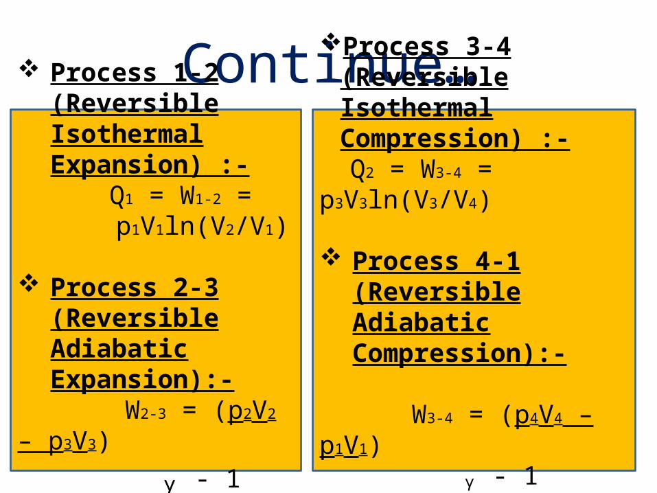
Continue…Process 3-4 (Reversible
Isothermal Compression) :- Q2 = W3-4 =
p3V3ln(V3/V4)
Process 4-1 (Reversible Adiabatic Compression):-
W3-4 = (p4V4 – p1V1) ᵧ - 1
= - mCv (T1-T2)
Process 1-2 (Reversible Isothermal Expansion) :-
Q1 = W1-2 = p1V1ln(V2/V1)
Process 2-3 (Reversible Adiabatic Expansion):-
W2-3 = (p2V2 – p3V3) ᵧ - 1
= mCv (T1-T2)

Continue…So, W = work done by the system – work done on system = mRT1 ln(V2/V1) – mRt2 ln(V3/V4) = Q1 – Q2.
ηth = net work output heat output
= W/Q = T1 – T2 = 1 – (T2/T1) T1

Otto cycleIt is also called as constant volume cycle because heat
is supplied and rejected at constant volume.
Nicholas-A-otto, a german engineer developed the first cycle which is first successful engine working on this cycle. So it is called as otto cycle.
This cycle consists of the two reversible adiabatic & two reversible isochoric process.

Continue…

Continue…The air-standard Otto cycle is the ideal cycle that
approximates the spark-ignition combustion engine.
Process Description 1-2 Isentropic compression 2-3 Constant volume heat addition 3-4 Isentropic expansion 4-1 Constant volume heat rejection
The P-v and T-s diagrams are shown in fig.(2)
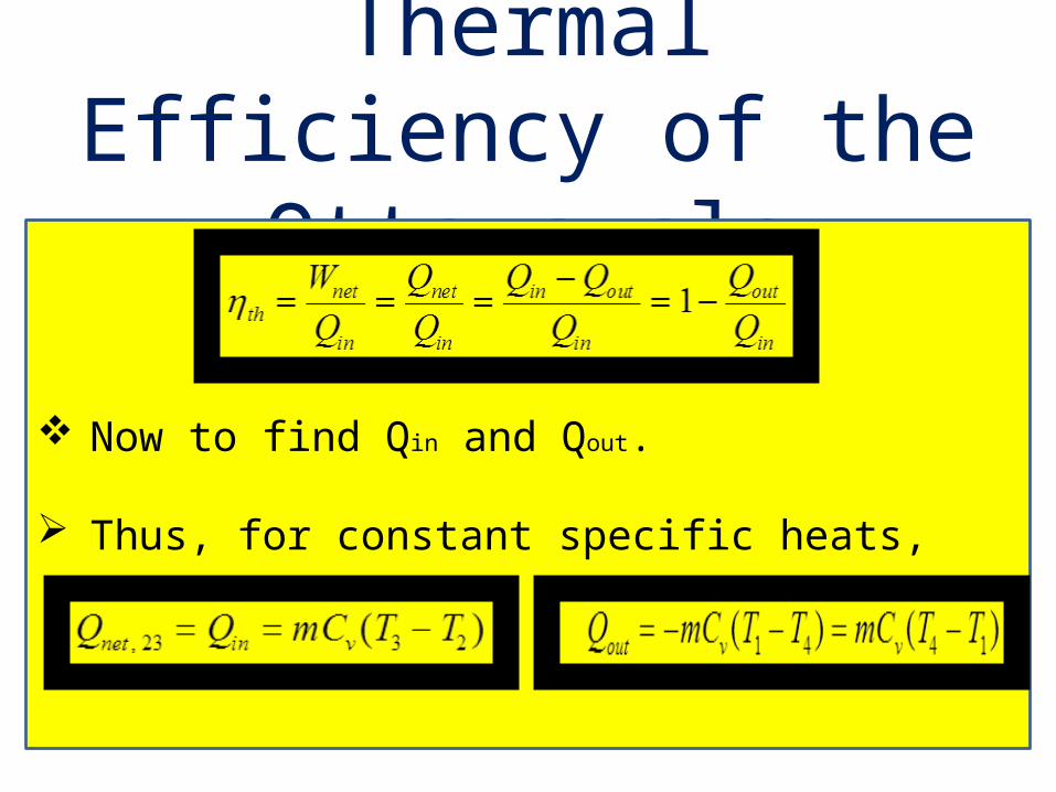
Thermal Efficiency of the Otto cycle
Now to find Qin and Qout. Thus, for constant specific heats,

The thermal efficiency becomes
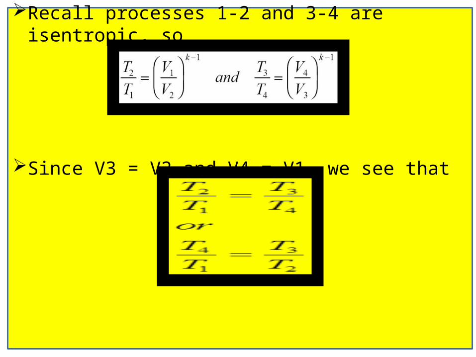
Recall processes 1-2 and 3-4 are isentropic, so
Since V3 = V2 and V4 = V1, we see that
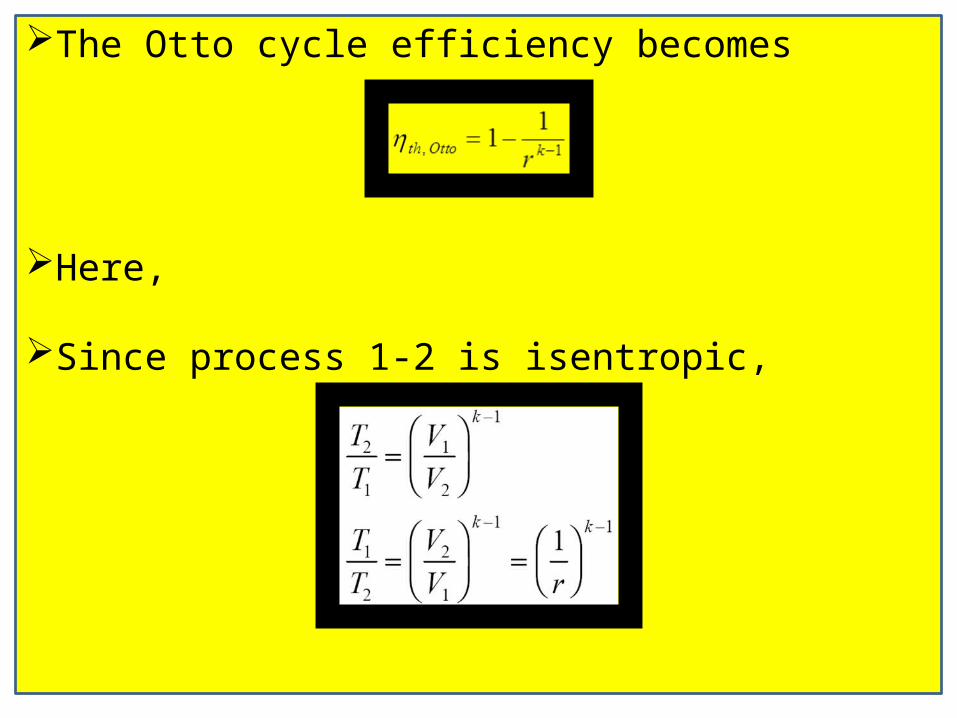
The Otto cycle efficiency becomes
Here,
Since process 1-2 is isentropic,
14
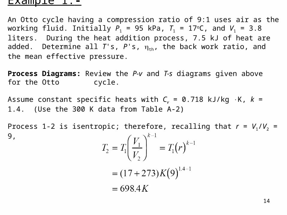
Example 1:-
An Otto cycle having a compression ratio of 9:1 uses air as the working fluid. Initially P1 = 95 kPa, T1 = 17oC, and V1 = 3.8 liters. During the heat addition process, 7.5 kJ of heat are added. Determine all T's, P's, th, the back work ratio, and the mean effective pressure. Process Diagrams: Review the P-v and T-s diagrams given above for the Otto
cycle.
Assume constant specific heats with Cv = 0.718 kJ/kg K, k = 1.4. (Use the 300 K data from Table A-2)
Process 1-2 is isentropic; therefore, recalling that r = V1/V2 = 9,

15
The first law closed system for process 2-3 was shown to reduce to (your homework solutions must be complete; that is, develop your equations from the application of the first law for each process as we did in obtaining the Otto cycle efficiency equation)
Q mC T Tin v ( )3 2
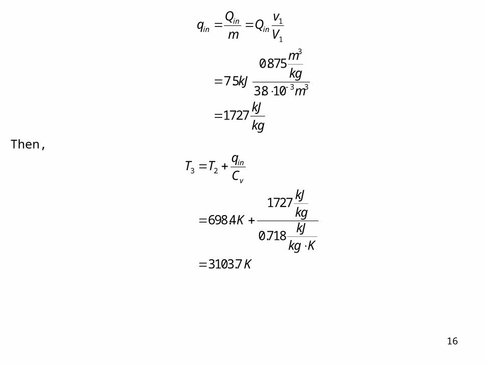
Let qin = Qin / m and m = V1/v1
vRT
P
kJkg K
K
kPa
m kPa
kJ
m
kg
11
1
3
3
0 287 290
95
0875
. ( )
.
16
mQv
V
kJ
mkgm
kJ
kg
inin
in
1
1
3
3 37 5
0875
38 10
1727
..
.
Then,
T Tq
C
K
kJkgkJkg K
K
in
v3 2
698 41727
0 718
31037
..
.
17
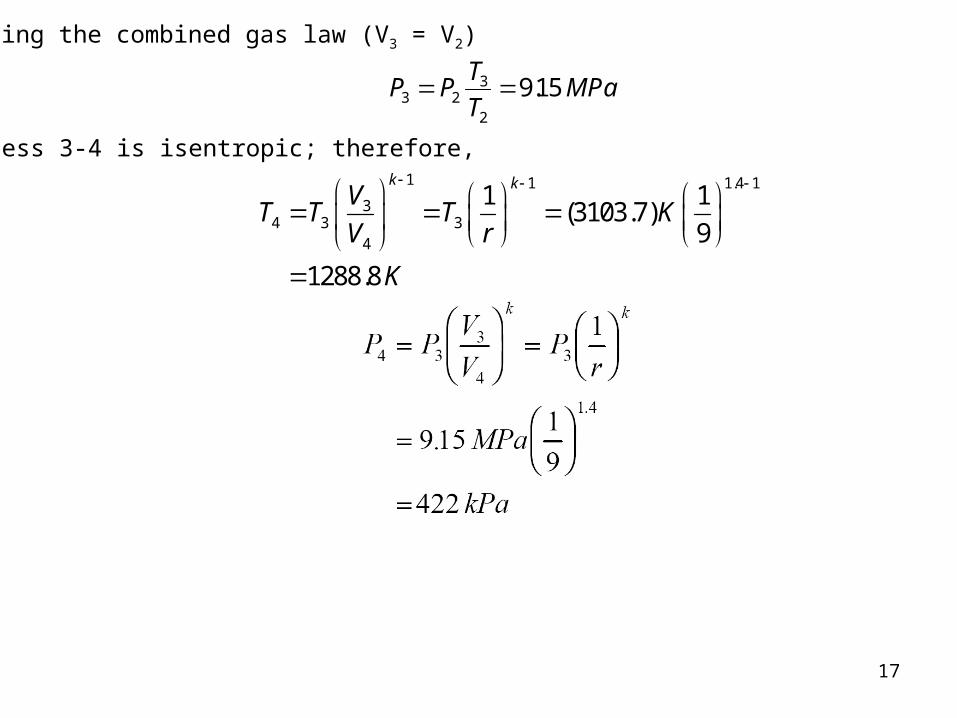
Using the combined gas law (V3 = V2)
P PT
TMPa3 2
3
2
915 .
Process 3-4 is isentropic; therefore, 1 1 1.4 1
34 3 3
4
1 1(3103.7)
9
1288.8
k kV
T T T KV r
K
18
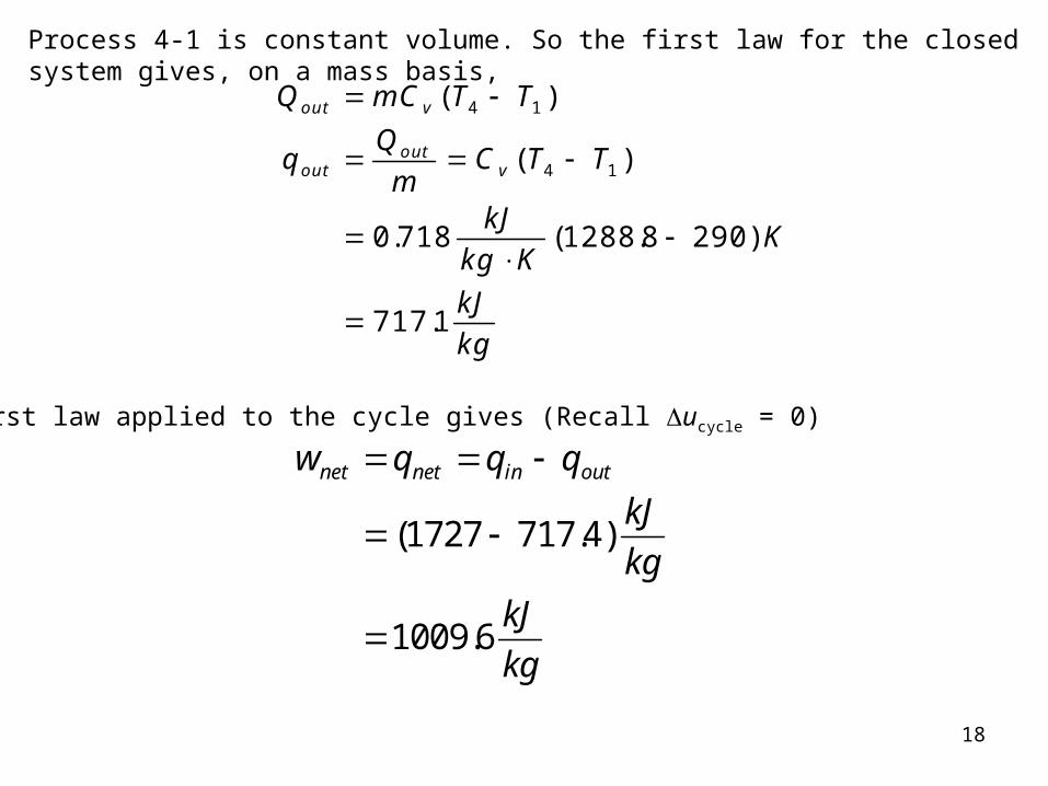
Process 4-1 is constant volume. So the first law for the closed system gives, on a mass basis,
Q mC T T
mC T T
kJ
kg KK
kJ
kg
out v
outout
v
( )
( )
. ( . )
.
4 1
4 1
0 718 12888 290
7171
The first law applied to the cycle gives (Recall ucycle = 0)
w q q q
kJ
kg
kJ
kg
net net in out
( . )
.
1727 717 4
1009 6

19
The thermal efficiency is
th Otto net
in
w
q
kJkgkJkg
or
,
.
. .
1009 6
1727
0585 585%
The mean effective pressure is
max min max min
1 2 1 2 1 1
3
3
(1 / ) (1 1/ )
1009.61298
10.875 (1 )
9
net net
net net net
W wMEP
V V v v
w w w
v v v v v v r
kJm kPakg
kPam kJkg
Diesel cycle
20

Continue…
21
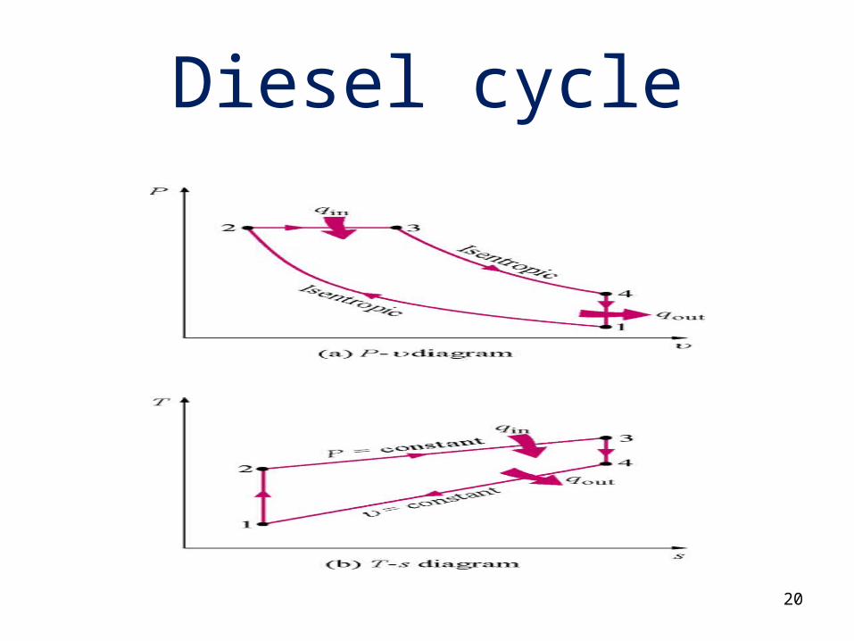
The air-standard Diesel cycle is the ideal cycle that approximates the Diesel combustion engine
Process Description 1-2 Isentropic compression 2-3 Constant pressure heat
addition 3-4 Isentropic expansion 4-1 Constant volume heat
rejection
The P-v and T-s diagrams are as shown in above figure.

22
Thermal efficiency of the Diesel cycle
Now to find Qin and Qout. Apply the first law closed system to process 2-3, P = constant.

23

The thermal efficiency becomes
24

Brayton Cycle
25
The Brayton cycle is the air-standard ideal cycle approximation for the gas-turbine engine. This cycle differs from the Otto and Diesel cycles in that the processes making the cycle occur in open systems or control volumes. Therefore, an open system, steady-flow analysis is used to determine the heat transfer and work for the cycle.
We assume the working fluid is air and the specific heats are constant and will consider the cold-air-standard cycle.

Schematic diagram of brayton cycle
26

Continue…
27
The T-s and P-v diagrams are shown in below figure.

28