gas-fired cast iron boilers for natural and … · galaxy low pressure steam—models gxha-100...
TRANSCRIPT
CONTENTS .........................................................................PAGEDimensions............................ ......................................................2Installation Requirements:
Boiler Location........................................ ................................3Boiler Foundation....................................................................3Chimney Requirements............................. .............................3
Minimum Clearance.....................................................................3Vent Piping..............................................................................4
Gas Piping............................................. ......................................4Electrical Controls and Wiring.................... ............................5Boiler Room Air Supply and Ventilation......... .........................5Draft Hood Installation.............................. ..............................5Piping at Boiler—Water Boilers................... ...........................6Steam Controls Assembly and Installation .............................6Piping a Steam Boiler .........................................................6,7Vent Damper.......................................... ..............................8,9
Operating Instructions:Filling and Venting Water Systems.............. ...........................9Initial Start, Safety and Lighting Instructions... ................10-11Burner Adjustment, Checking Gas Input...... ........................12Controls, Safety Check .........................................................13
Low Water Cut-off Check-Out....................................................13Pressure Control Check-Out .....................................................13Blowing Off a Steam Boiler........................................................14Care and Maintenance.................................. ............................15
Safety Check for Control System..........................................16Protection From Freezing.......................... ...........................16Water Treatment....................................................................16
Sequence of Operations............................................................17Wiring Diagrams.......................................... .........................18-25Pump or Valve Zoning—Water Boilers.............. ........................26Troubleshooting Guide...............................................................27Piping a Heating and Cooling System.......................................28Replacement Parts...................................... ..............................28Appendix A ................................................................................29
IMPORTANTREAD ALL OF THE FOLLOWING WARNINGS AND
STATEMENTS BEFORE READING THE INSTALLATION INSTRUCTIONS
WARNINGLIQUEFIED PETROLEUM (L.P.)
PROPANE GAS-FIRED BOILERS
Installation location ONLY as permitted in paragraph entitled"LIQUEFIED PETROLEUM (L.P.) PROPANE GAS-FIREDBOILER LOCATION" on page 3 of this instruction book.The above warning does not apply to NATURAL gas-fired boilers.
The installation must conform to the requirements of the authori-ty having jurisdiction or, in the absence of such requirements, tothe National Fuel Gas Code, ANSI Z223.1-latest edition. Theinstallation must also conform to the additional requirements inthis Slant/Fin Instruction Book.
In addition, where required by the authority having jurisdiction,the installation must conform to American Society of MechanicalEngineers Safety Code for Controls and Safety Devices forAutomatically Fired Boilers, No. CSD-1.
This manual must be left with owner and should be hung on oradjacent to the boiler for reference.
WARNINGThis boiler, gas piping and accessories must be installed, con-nected, serviced and repaired by a trained, experienced servicetechnician, familiar with all precautions required for gas-firedequipment and licensed or otherwise qualified, in compliancewith the authority having jurisdiction.
Printed in U.S.A. 706 PUBLICATION GG-40Part No. 41-0549 Rev. I
INSTALLATION AND OPERATING INSTRUCTIONS
HOT WATER—Models GG-75H through GG-399HLOW PRESSURE STEAM AND HOT WATER—
Models GXH-105 through GXH-300H and Models GX-225 and GX-250LOW PRESSURE STEAM—Models GXHA-100 through GXHA-200GALAXY
GAS-FIRED CAST IRON BOILERS FOR NATURAL AND L.P. PROPANE GASES™
Heating Contractor
Address
Phone Number
Boiler Model Number
Boiler Serial Number
Installation Date

2 GALAXY
ORIFICE SIZES indicated for Sea Level are factory installed inboiler unless otherwise specified by the local authority.See VII, page 12 for burner input adjustment.GAS VALVE CONNECTION Size is 1/2" f.p.t. for all sizes up to andincluding GG-225 and GX-225. Larger boilers, gas valves may be 3/4" or1/2" depending upon configuration (natural, L.P., standing pilot, IID).COMBUSTIBLE FLOOR KIT increases all height dimensions by 1".RAISED SLAB - When mounting boiler on a raised slab, the slabmust extend at least 2" beyond the boiler cabinet on all sides.CHIMNEY HEIGHT: 15 ft. minimum from draft hood skirt to top ofchimney. CHIMNEY INSIDE DIAMETER must be same as Dimen-sion “C” or larger. Larger diameter and/or height may be required iftwo or more boilers or a boiler and another appliance are vented toa single chimney.
GG-75H GG-100H GG-125H GG-150H GG-175H GG-200H GG-225H GG-250H GG-275H GG-300 GG-325 GG-350 GG-350H GG-375H GG-399HA 193⁄4 193⁄4 193⁄4 23 23 261⁄2 261⁄2 293⁄4 293⁄4 331⁄4 331⁄4 361⁄2 361⁄2 361⁄2 361⁄2B 131⁄4 131⁄4 131⁄4 161⁄2 161⁄2 20 20 231⁄4 231⁄4 263⁄4 263⁄4 30 30 30 30C 5 6 6 6 6 7 7 8 8 8 8 9 9 10 10D 463⁄8 531⁄4 531⁄4 531⁄4 531⁄4 571⁄2 571⁄2 595⁄8 595⁄8 595⁄8 661⁄8 661⁄8 661⁄8 595⁄8 625⁄8E 63⁄4 13 13 13 13 16 16 17 17 17 17 221⁄2 221⁄2 15 18F 8 8 8 93⁄4 93⁄4 111⁄4 111⁄4 13 13 143⁄4 143⁄4 161⁄4 161⁄4 161⁄4 161⁄4G 11⁄4 11⁄4 11⁄4 11⁄4 11⁄4 11⁄4 11⁄4 11⁄2 11⁄2 11⁄2 11⁄2 11⁄2 11⁄2 11⁄2 11⁄2H 11⁄2 11⁄2 11⁄2 11⁄2 11⁄2 11⁄2 11⁄2 11⁄2 11⁄2 11⁄2 11⁄2 11⁄2 11⁄2 11⁄2 11⁄2J 23⁄4 23⁄4 23⁄4 23⁄4 23⁄4 23⁄4 23⁄4 23⁄4 23⁄4 23⁄4 23⁄4 23⁄4 23⁄4 23⁄4 23⁄4K 91⁄4 91⁄4 91⁄4 91⁄4 91⁄4 91⁄4 91⁄4 91⁄4 91⁄4 91⁄4 91⁄4 91⁄4 91⁄4 91⁄4 91⁄4
GXHA-100 GXH-105 GXHA-120 GXH-125 GXH-150 GXHA-160 GXH-170 GXH-190 GXHA-200 GXH-210 GX-225 GXH-230 GX-250 GXH-250 GXH-275 GXH-300HA – 23 – 23 261⁄2 – 261⁄2 261⁄2 – 293⁄4 293⁄4 293⁄4 293⁄4 321⁄2 321⁄2 321⁄2B 161⁄2 161⁄2 161⁄2 161⁄2 20 20 20 20 231⁄4 231⁄4 231⁄4 231⁄4 231⁄4 26 26 26C 5 5 5 6 7 6 7 7 7 7 8 7 8 7 7 9D – 463⁄8 – 531⁄4 551⁄2 – 551⁄2 551⁄2 – 551⁄2 565⁄8 551⁄2 565⁄8 551⁄2 551⁄2 591⁄8E – 63⁄4 – 13 14 – 14 14 – 14 14 14 14 14 14 15F 10 93⁄4 10 93⁄4 111⁄4 113⁄4 111⁄4 111⁄4 131⁄2 111⁄4 13 13 13 143⁄4 143⁄4 143⁄4G – 11⁄4 – 11⁄4 11⁄4 – 11⁄4 11⁄2 – 11⁄2 11⁄2 11⁄2 11⁄2 11⁄2 11⁄2 11⁄2H – 21⁄2 – 21⁄2 21⁄2 – 21⁄2 21⁄2 – 21⁄2 21⁄2 21⁄2 21⁄2 21⁄2 21⁄2 21⁄2J – 31⁄2 – 31⁄2 31⁄2 – 31⁄2 31⁄2 – 31⁄2 31⁄2 31⁄2 31⁄2 31⁄2 31⁄2 31⁄2K – 93⁄4 – 93⁄4 93⁄4 – 93⁄4 93⁄4 – 93⁄4 93⁄4 93⁄4 93⁄4 93⁄4 93⁄4 93⁄4L – 1⁄2 – 1⁄2 1⁄2 – 1⁄2 1⁄2 – 3⁄4 3⁄4 3⁄4 3⁄4 3⁄4 3⁄4 3⁄4M 285⁄8 – 285⁄8 – – 285⁄8 – – 285⁄8 – – – – – – –
GG SERIES HOT WATER BOILERS - DIMENSIONS IN INCHES
GX, GXH AND GXHA SERIES STEAM AND HOT WATER BOILERS - DIMENSIONS IN INCHES
FRONT VIEWAll GG and GX(H)
RIGHT SIDEGG / GX(H)-PT
RIGHT SIDEGX(H)-PZT-PPZT
RIGHT SIDEGX(H)-PZ
GG/GX Natural 42 43 43 43 43 44 44 45 46 47Except GG-399H Propane 54 54 55 55 55 55 55 56 56 56
GG-399H Natural 40 41 42 42 42 43 43 44 44 45Propane 53 54 54 54 54 54 54 55 55 55
GXH-105 Natural 44 45 45 45 46 47 47 48 48 49through 275 Propane 54 54 55 55 55 55 55 56 56 56
GXH-300 Natural 43 44 44 44 45 45 46 47 47 48Propane 54 54 55 55 55 55 55 56 56 56
GXH-300H NaturalGG-350H Gas* 43 44 44 44 45 45 46 47 47 48
GXHA Natural 45 46 47 47 47 48 48 49 49 50Propane 55 55 55 55 56 56 56 56 56 57
BOILER MODEL GAS TYPE 2,000
ELEVATION–FEET
ORIFICE SIZES AT HIGH ALTITUDESINCLUDES 4% INPUT REDUCTION FOR EACH 1000 FEET
3,000 4,000 5,000 6,000 7,000 8,000 9,000 10,000
OrificeSize for
Sea Level
*For L.P. Propane gas, consult factory.
BOILER DIMENSIONS
GXHA Series

GALAXY 3
GALAXY GG SERIES
INSTALLATION REQUIREMENTSThe installation must conform to the requirements of the author-ity having jurisdiction or, in the absence of such requirements,to the National Fuel Gas Code, ANSI Z223.1-latest edition.
This installation must also conform to the additional require-ments in this Slant/Fin instruction book. Installation and serviceto be performed by a qualified installer, service agency or thegas supplier.
NATURAL GAS-FIRED BOILER LOCATION—
Provide a level, solid foundation for the boiler. Location shouldbe as near the chimney as possible so that the flue pipe fromboiler to chimney is short and direct.
Automatic gas ignition system components shall be installed sothese components will not be subjected to dripping water duringinstallation or service.
WARNINGLIQUEFIED PETROLEUM (L.P.) PROPANE GAS-FIREDBOILER LOCATION
REQUIRES SPECIAL ATTENTIONLiquefied Petroleum (LP) propane gas is heavier than air.Therefore, propane boilers, piping, valves should NOT beinstalled in locations where propane leaking from defectiveequipment and piping will "pool" in a basement or otherspace below the leak.
A spark or flame from the boiler or other source may ignitethe accumulated propane gas causing an explosion or fire.Provide a level, solid foundation for the boiler. Locationshould be as near the chimney as possible so that the fluepipe from boiler to chimney is short and direct.
THE UNIFORM MECHANICAL CODE may be in effect inyour geographic area.The following precautions are cited by the 1994 UNIFORMMECHANICAL CODE, section 304.6:
"LPG Appliances. Liquefied petroleum gas-burningappliances shall not be installed in a pit, basement orsimilar location where heavier-than-air gas might collect.Appliances so fueled shall not be installed in an above-grade under-floor space or basement unless such loca-tion is provided with an approved means for removal ofunburned gas."
Consult Chapter 5 of the 1994 UNIFORM MECHANICALCODE for design criteria of the "approved" means forremoval of unburned gas.
CHIMNEY REQUIREMENTS—A. Galaxy boilers may be vented into a masonry vitreous tile-
lined chimney or UL LISTED Type “B” Venting system NOTEXPOSED to the OUTDOORS below the roof line.Venting and sizing of venting system must be in accordancewith Part 7, Part 10 and Appendix G of the National FuelGas Code ANSI Z223.1, NFPA 54, -latest edition which willbe referred to as the National Fuel Gas Code. Local codesapply.If a masonry chimney is exposed to the outdoors on one ormore sides below the roof line (exterior chimney), ONE ofthe following options apply:1. Chimney must be re-lined with a UL LISTED metallic liner.
When this is done, the chimney will be considered NOTexposed to the outdoors and the requirements of theNational Fuel Gas Code for NON-exposed chimneysand/or local codes will apply.
2. If an exposed tile-lined chimney is to be used WITHOUT aUL LISTED metallic liner, the boiler must first meet therequirements of the following tables and paragraphs of theNational Fuel Gas Code:I. For Single Galaxy Boiler - Paragraph 10.1.9 and table
10.11.II. For multiple appliances - Paragraph 10.2.18 and table
10.12 (or 10.13 if applicable).In addition, all requirements of Part 7, Part 10 andAppendix G of the National Fuel Gas Code and/or localcodes apply.
B. If an existing boiler is removed from a common venting sys-tem, the common venting system may be too large for prop-er venting of the remaining appliances connected to thecommon vent. Follow the test procedure shown in Appendix"A" on page 28 of this manual to insure proper operation ofventing system and appliances.
C. Inspect for proper and tight construction. Any restrictions orobstructions must be removed. An existing chimney mayrequire cleaning.
D. Chimney or vent must extend at least 3 feet above its pas-sage through a roof and at least 2 feet above any ridge with-in 10 feet of the chimney.
MINIMUM CLEARANCES FROM COMBUSTIBLE CON-STRUCTION —A. Minimum boiler clearances shall be as follows:
BOILER FOUNDATION
A. Provide a solid, level foundation, capable of supporting theweight of the boiler filled with water, and extending at least2" past the jacket on all sides. See dimensions of boilers,page 2.
B. For installation on non-combustible floors only.*
C. If boiler is to be located over buried conduit containing elec-tric wires or telephone cables, consult local codes or theNational Board of Fire Underwriters for specific require-ments.* The Combustible Floor Kit part number printed on the boiler rating plate is
the only one to be used when installing on combustible floors. The boilermust NOT be installed on carpeting. DO NOT place boilers above floorarea containing radiant tubing.
MODELS GG-75HTHROUGH GG-225H.MINIMUM CLEARANCEFOR COMBUSTIBLECONSTRUCTION.MINIMUM CLOSETCLEARANCE.Front 6"Rear 6"Left Side 6"Right Side 6"Top 36"Flue Connector 6"Type 'B' Vent 1"
MODELS GG-250THROUGH GG-399H.MINIMUM CLEARANCEFOR COMBUSTIBLECONSTRUCTION.MINIMUM ALCOVECLEARANCE.Front AlcoveRear 6"Left Side 6"Right Side 6"Top 36"Flue Connector 6"Type 'B' Vent 1"

4 GALAXY
B. Provide accessibility clearance of 24" on sides requiring ser-vicing and 18" on sides used for passage.
C. All minimum clearances shown above must be met. Thismay result in increased values of some minimum clearancesin order to maintain the minimum clearances of others.
D. Clearance from steam and hot water pipes shall be 1". **** At points where hot water or steam pipes emerge from a floor, wall or ceil-
ing, the clearance at the opening through the finished floor boards or wallor ceiling boards may be not less than 1/2". Each such opening shall becovered with a plate of noncombustible material.
SAFETY—
KEEP THE BOILER AREA CLEAR AND FREE FROM COMBUSTIBLE MATERIALS, GASOLINE AND OTHER FLAMMABLE VAPORS AND LIQUIDS.
VENT PIPING—A. Vent piping installation must be in accordance with ANSI
Z223.1-latest edition, National Fuel Gas Code, Part 7,Venting of Equipment. Other local codes may also applyand must be followed.
B. Boiler vent pipe must be the full diameter of the boiler drafthood outlet. See dimensions, page 2. If a vent damper isadded, its diameter must be equal to the hood outlet andmust be located past the hood outlet. See installationinstructions furnished with vent damper and in the section"Vent Damper Installation" of this instruction book.
C. If more than one appliance vents into a common breeching,the area of the breeching must be equal to the area of thelargest vent plus 50% of the area of the additional ventareas. Vent connectors serving appliances vented by naturaldraft shall not be connected into any portion of mechanicaldraft systems operating under positive pressure. Horizontalbreeching or vent pipe should be as high as possible, con-sistent with codes, so that vertical vents from appliances willhave a high rise above draft diverter openings. All horizontalruns must slope upwards not less than 1/4 inch per foot ofrun. Horizontal portions of the venting system must be sup-ported to prevent sagging by securing each joint with metalscrews and by providing hangers spaced no greater than 5feet apart.
D. Vent or breeching into chimney should not be inserted pastthe inside wall of the chimney liner.
E. All venting means should be inspected frequently. See Careand Maintenance and separate User's Information Manual.
GAS PIPING—A. Local installation codes apply. The pipe joint compound used
on threads must be resistant to the action of liquefied petro-leum gases.
B. The gas supply line to the boiler should be run directly fromthe meter for natural gas or from the fuel tank for L.P.propane gas. See page 2 for location of union and manualmain shut-off valve that may be specified locally.Selecting pipe size for natural gas:1. Measure or estimate the length of piping from the meter to
the installation site.2. Consult gas supplier for heating value of gas (BTU/cu. ft.).3. Divide boiler rated input by heating value to find gas flow
in piping (cu. ft. per hour).4. Use table below to select proper pipe size.Example: Boiler model GG-300 is to be installed. Distancefrom gas meter to the boiler is 50 ft. Heating value of naturalgas is 1020 BTU/cu. ft. Select proper pipe size.
At 50 ft. length of pipe, match required capacity from tablebelow (choose higher capacity, in this case is 440 cu. ft. perhour). Required pipe size is 1-1/4". Improper gas pipe sizingwill result in pilot flame outages, insufficient heat and otherinstallation difficulties. For more information and also if otherappliances are to be attached to the piping system, seeAppendix C of National Fuel Gas Code ANSI Z223.1-latestedition.
C. The boiler and its gas connection must be leak tested beforeplacing the boiler in operation. Use liquid soap solution forall gas leak testing. DO NOT use open flame.This boiler and its individual shut-off valve must be discon-nected from the gas supply piping system during any pres-sure testing of that system at test pressures in excess of 1/2PSIG.This boiler must be isolated from the gas supply piping sys-tem by closing its individual manual shut-off valve during anypressure testing of the gas supply piping system at testpressures equal to or less than 1/2 PSIG.
D. All gas piping used should be inspected thoroughly forcleanliness before makeup. A sediment trap must be provid-ed, as illustrated on page 2.
E. The minimum and maximum gas supply pressure (at theinlet of gas valve) are shown on the boiler rating plate for thetype of gas used. Gas supply pressure should never be lessthan minimum or more than maximum pressure when theboiler or any other appliance is turned on or off.
GALAXY GX GXH SERIES GXHA SERIES
MODELS GXH-105THROUGH GXH-190 MINIMUM CLEARANCEFOR COMBUSTIBLECONSTRUCTION.MINIMUM CLOSETCLEARANCE.
Front 6"Rear 6"Left Side 6"Right Side 18"Top 36"Flue Connector 6"Type 'B' Vent 1"
MODELS GXH-210 TOGXH-300H, GX-225 TOGX-250.MINIMUM CLEARANCEFOR COMBUSTIBLECONSTRUCTION.MINIMUM ALCOVECLEARANCE.Front AlcoveRear 6"Left Side 6"Right Side 18"Top 36"Flue Connector 6"Type 'B' Vent 1"
MODELS GXHA-100,GXHA-120, GXHA-160& GXHA-200MINIMUM CLEARANCEFOR COMBUSTIBLECONSTRUCTION.CLOSET AND ALCOVECLEARANCE.Front 6"Rear 6"Left Side 6"Right Side 18"Top 18"Flue Connector 6"Type 'B' Vent 1"
1/2 3/4 1 1-1/4 1-1/2
10 132 278 520 1050 160020 92 190 350 730 110030 73 152 285 590 89040 63 130 245 500 76050 56 115 215 440 67060 50 105 195 400 61070 46 96 180 370 56080 43 90 170 350 53090 40 84 160 320 490100 38 79 150 305 460
Lengthof Pipein Feet
Gas Flow In Piping — cu. ft. per hr.
Iron Pipe Size (IPS) — inches
Gas flow = 300,000 BTU/hour = 294 cu. ft. per hour1020 BTU/cu. ft.

GALAXY 5
ELECTRICAL CONTROLS AND WIRING—A. The electrical power to the boiler must be on a separately
fused and live circuit.
B. If an external electrical source is utilized, the boiler, wheninstalled, must be electrically grounded in accordance withthe requirements of the authority having jurisdiction or, inabsence of such requirements, with the National ElectricalCode, ANSI/NFPA No. 70-latest edition.
C. Basic control wiring diagrams are given on pages 18-25.Other control systems may be factory supplied, see User'sInformation Manual and Instructions packed with controlsystem supplied.
D. After placing the boiler in operation, the safety shut-offdevice must be tested. See page 13 safety check.
BOILER ROOM AIR SUPPLY AND VENTILATIONAn ample supply of air is required to obtain combustion andventilation. Room temperature over 100°F may cause nuisancetripping of the Blocked Vent Safety Switch.
ALL AIR MUST COME FROM OUTSIDE, directly through wallopenings to the boiler or through unsealed openings aroundwindows, doors, etc. in the whole building. When buildings areinsulated, caulked and weather-stripped, now or later on, directopening to outside may be required and should be provided. Ifthe boiler is not on an outside wall, air may be ducted to it fromoutside wall openings.
The National Fuel Gas Code, ANSI Z223.1-latest edition speci-fies openings for air under various conditions. Local codes mayspecify minimum opening sizes and locations. The followingrecommendation applies to buildings of energy-saving construc-tion, fully caulked and weather-stripped:
Provide one GRILLED opening near the floor and one near theceiling on an outside wall near the boiler (or duct from suchopenings to the boiler), EACH opening to be a minimum of onesquare inch per 2000 Btuh input to ALL APPLIANCES in thearea. For a total appliance input of 200,000 Btuh, each open-ing will be 100 square inches. A grilled opening 10" x 10" has100 square inches of area. If fly screen must be used overopenings, double the area and inspect and clean the screenfrequently.
Openings must NEVER be reduced or closed. If doors or win-dows are used for air supply, they must be locked open.Protect against closure of openings by snow and debris.Inspect frequently.
NO MECHANICAL DRAFT EXHAUST OR SUPPLY FANS ARETO BE USED IN OR NEAR THE BOILER AREA.
The flow of combustion and ventilating air to the boiler mustNOT be obstructed.
DRAFT HOOD—The draft hood supplied is part of the listed boiler assembly.DO NOT alter the hood. See dimensions, page 2.
SPECIAL FLUSHING INSTRUCTIONSInstallation of new boiler may break loose a heavyaccumulation of sediment and scale from old pipingand radiators. It is extremely important to blowdown your McDonnell Cut-off 67 more frequentlythe first week.First week — 3 timesThereafter — at least once a week* Exception: McDonnell Cut-off 42A must be blowndown daily.See "CARE AND MAINTENANCE" for instructions.

6 GALAXY
1/4" brass fittings.6. Install water level gauge (without glass) and its fittings.7. Install water level glass, and mark the glass 25-1/2" from the
bottom of the steel boiler base for the water level. (Thesteel boiler base should not be confused with a combustiblefloor kit when making the 25-1/2" measurement.)
8. Drain cock will be installed in return tee at the lower rightside of casting.
9. Safety valve and 3/4" street coupling should be installed in3/4" tapping on top of boiler.
PIPING A LOW PRESSURE STEAM BOILERBoilers must be piped with good engineering practice and mustconform to the requirements of ANSI/ASME Boiler andPressure Vessel Code section IV and to the authority havingjurisdiction.NOTES:1. Slant/Fin makes no recommendation, nor does Slant/Fin
imply that One Pipe Parallel and Counterflow GravityCondensate Return systems shown on page 7 are the pre-ferred systems. These systems are merely two examples ofmany possible systems. Determination of the proper systemis based upon the application and is therefore beyond thescope of this instruction.
2. The 18" minimum height shown in figures 1-3, is the mini-mum height between the top of the jacket of the boiler andthe 2-1/2" x 12" header centerline in the supply piping fromthe boiler. It must NOT be confused with the minimumheight between the water level and the lowest return bend ofthe steam supply main. This height is "H" as shown in fig-ures 2 and 3.The minimum height of "H" must be at least equal to thesum of the pressure drop of the system plus three times thefriction loss of the wet return, but not less than 18" for a sys-tem with a 1/8" psi steam pressure drop and not less than28" for a system with a 1/2" psi steam pressure drop.
3. Modern steam boilers are smaller in water content than theboilers that they replace, therefore a mechanical return sys-tem (pump, receiver, etc.) must be employed if conditionsexist such that uniform condensate return flow to the boilercannot be maintained.Pocketing of condensate and the inability to maintain thecorrect minimum height between the steam supply main andthe water level in the boiler are but a few of the many condi-tions that indicate the use of a mechanical return system.Any use of a receiver and pump must be coordinated withthe makeup water and controlled by the boiler water levelcontrol on the boiler. This description is typical of a boilerfeed pump as opposed to a condensate pump that pumpscondensate regardless of the water level in the boiler.
4. In any steam system one of the requirements is the removalof air from the system. A mechanical return system in mostcases has an air vent on the receiver. A gravity return sys-tem has no receiver, so provisions for air removal must bemade on the piping itself. A one pipe system has the airvents on the radiation, the heat exchanger and near the endof the steam supply main (see figures 2 and 3).Main air vents should be located fifteen inches from the dripand if possible eight inches above the pipe so that waterhammer does not damage the vent and render the ventinoperable.For more information on air vents, check with any manufac-turer of steam accessories (steam traps, boiler feed pumps,air vents, etc.).
5. Process water applications involving steam boilers requires
Attach the hood to the boiler flue outlet. Connect flue pipe fullsize of hood outlet. If a vent damper is added, it must beinstalled on the outlet side of the hood. See Vent Piping, onpage 4.
PIPING AT BOILER — WATER PIPINGI. CIRCULATING SYSTEMS
A.Packaged water boilers are equipped with a water circulat-ing pump, mounted to return the water into the boiler. Forsome installations, the pump should be on the supply main. See PUMP LOCATION, below.
II. AIR CONTROL SYSTEMA.DIAPHRAGM-TYPE COMPRESSION TANKS are used to
control system pressure in an AIR ELIMINATING SYS-TEM: an automatic air vent is used to REMOVE air fromthe system water. See illustration on page 5.If system pressure needs further control, add an additionaltank or install a larger capacity tank.Locate the tank near the boiler, as illustrated.An automatic air vent should be installed in the top of theboiler. See illustration on page 5.
B.PUMP LOCATION — Locating low-head pump(s) onreturn to boiler is acceptable for smaller boiler sizes in res-idences of one or two stories. The alternate pump loca-tion shown in illustration on page 5 is required in large,multi-story building installations, especially when high-head pumps are used. The compression tank must be atthe boiler or between boiler and supply main pump(s).
C.On a hot water boiler installed above radiation level,theboiler must be provided with a low water cut-off device atthe time of installation by the installer.
Flow Control Valve: When domestic hot water tankless heater is used,a flow control valve should be installed in supply piping to heating sys-tem, as shown in illustration on page 5.
INSTALLATION INSTRUCTIONS FOR GXH LOW PRESSURESTEAM BOILERS EQUIPPED WITH TANKLESS OR PROVISION FOR TANKLESS AND McDONNELL & MILLERTYPE 67 LOW WATER CUT-OFF.STEAM CONTROLS ASSEMBLY AND INSTALLATIONINSTRUCTIONSSteam kit components for Galaxy packaged models are packedas follows:A. 1. Low water cut-off control
2. Fittings3. L.W.C.O. instruction sheet
B. 1. Pressure gauge2. High pressure limit control3. Water level gauge4. Fittings5. Instruction sheet and assembly drawing6. Steam safety valve and 3/4" street coupling7. Drain cock8. Thermostat
Assemble above components exactly as shown in steam con-trols assembly. Two 1/2" tappings are on right side of boiler forthis assembly. Two holes are pre-punched in jackets. For con-venience, start assembling in the following steps:1. Install 1/2" x 5-1/2" brass nipple onto tee of L.W.C.O.2. Mount 1/2" x 5-1/2" brass nipple into lower boiler tapping by
rotating low water cut-off.3. Assemble 90° brass tubing to tee adapter and L.W.C.O.4. Install 1/2" x 6" brass nipple and 1/2" x 5/8" adapter tee in
upper boiler tapping.5. Install syphon, high pressure limit and pressure gauge with

GALAXY 7
the use of heat exchangers. Any process application thatconstantly uses fresh water into a steam boiler can and willcause scaling with deposits forming in the boiler and sur-rounding piping. This will damage the boiler.
6. If valves are used on the supply side of the boiler, the valveport opening must be the same size as the surroundingpipe. (Full flow type valves.)
7. Piping should provide a means of cleaning and flushing theheating system of the sediment for safe, efficient operation.
RECOMMENDED PIPING FOR A ONE PIPE PARALLELFLOW LOW PRESSURE STEAM HEATING SYSTEM WITH AWET OR DRY GRAVITY (See Note No. 3) CONDENSATERETURN AND A HARTFORD† LOOP.See Note No. 1 on page 6.
FIGURE 1
† A Hartford Loop is recommended for low pressure steam systems withgravity condensate returns.Pipe sizes shown above for Hartford Loop are recommended bySlant/Fin. However, certain local codes may require larger pipe sizes.Consult with local authorities.
∆ The equalizer should be full size from the steam supply to the operatingwater level.
* Hot water fill is preferable. For auto feedings, see manufacturer's tech-nical instructions.
FIGURE 2
* Hot water fill is preferable, but not required. For auto feeding, see manu-facturer’s technical instructions.
Counter flow piping is sized one pipe size larger than a parallel flow piping.This allows steam to travel in one direction while the condensate travels inthe other direction. This along with a steeper pitch is a must for safe, effi-cient operation.
FIGURE 3

8 GALAXY
VENT DAMPER INSTALLATION The vent damper referred to in the following instructions is theSlant/Fin Corporation vent damper.I. This device is design certified by A.G.A. for use ONLY on
specific Slant/Fin Corp. gas boiler models. These boilersmust also be equipped with a plate which states that theboiler must or may be used with a Slant/Fin Corp. automaticvent damper device and indicates the proper vent dampermodel number. This device cannot be used with millivoltignition system or boilers with input of 300,000 Btu/hr. orgreater equipped with continuous pilot.
II. A.INSTALLATION INSTRUCTIONS BEFORE YOU STARTTO INSTALL1. Read this installation manual, the "DANGER" plate
attached to the top of the boiler, the "WARNING" on thewiring diagrams, vent damper carton and operator cover.
2. Perform pre-installation inspection as required by ANSIspecification Z21.66.
3. Turn off all electrical power, gas supply and wait for sys-tem to cool (for previously installed boilers).
4. Select a proper, convenient location (see figures 4 and 5).5. Carefully unpack the unit. DO NOT FORCE IT OPEN
OR CLOSED. Forcing the damper may damage thegear train and void the warranty.
WARNING—DANGEROnce you have begun vent damper installation procedure, DONOT restore electric power and gas supply until installation andinspection have been completed (in order to prevent the mainburners from operating). DO NOT operate the boiler until thevent damper harness "RECEPTACLE B" is plugged into "MALEPLUG" (as described in the installation instructions), and thevent damper installation and checkout procedures have beencompleted. Failure to observe this warning may create a haz-ardous condition that could cause an explosion or carbonmonoxide poisoning.
B.1. This device must be installed after the appliance drafthood (between the draft hood outlet and the connectorto the outdoor chimney or vent) as close to the drafthood as practicable, and without modification of thedraft hood or the damper. (See figures 4 and 5.)
2. The inlet size of the vent damper must be the samenominal trade size as the outlet of the draft hood.
3. This device must be located in a venting system or sec-tion of a venting system so that it serves only the singleappliance for which it is installed. (See fig. 9.)
4. Clearances of not less than 6 inches (152mm) must bemaintained from combustible materials, with provisionsfor access for service.
5. GXHA steam boilers are equipped with integral draftdiverter consists of front section (factory assembled to the boiler) and the rear section (shipped with the boiler).The rear section must be assembled to the boiler using three sheet metal screws (see figure 7).Vent damper may be installed vertical or horizontal(see figure 8a & 8b)
C.NOW, PROCEED AS FOLLOWS:1. Remove the front cover of the boiler exposing the wiring
compartment. With all electrical power to boiler off,locate "MALE PLUG" (if boiler has an input of 300,000Btu/hr. or greater, locate "Receptacle A") (see wiringdiagram attached to boiler); a copy of this may also befound in this manual. To find the correct wiring diagramin this manual, match the number found in the lower
FIGURE 4
FIGURE 5
FIGURE 6
FIGURE 7

GALAXY 9
right hand corner of the boiler wiring diagram with theidentical number on one of the diagrams in this manual.)If the boiler has an input of 300,000 Btu/hr. or greater,cut the RED wire connected between numbers 3 and 4of "RECEPTACLE A" (the only wire connected to thisreceptacle) and then disconnect "RECEPTACLE A" from"MALE PLUG". Remove "RECEPTACLE A" from jobsite and discard.
2. Separate the vent pipe directly on top of the draft hoodor diverter and place damper in position as shown in fig-ures 4 - 9. The vent damper must be installed so thatthe damper position indicator is in a visible location afterinstallation for position indicator description. The arrowimprint on the damper should point in direction of ventgas flow (towards chimney). Re-assemble the vent pip-ing. Be sure the vent damper is well seated and fas-tened with 3 sheet metal screws. Screws should be nolonger than 1/2 inch.
3. Be sure that undersized vent pipe does not block move-ment of damper vane.
4. Boilers that may have vent damper are factory wiredwith plug and "RECEPTACLE A". To install the ventdamper all that is required is removal of the "RECEPTA-CLE A" and connection of the vent damper harness tothe boiler plug. (Remove "RECEPTACLE A" from jobsite and discard.) Boilers that must have a vent damperare factory wired with plug only.a)Attach the flexible metallic conduit vent damper har-
ness to the right hand side of the jacket by passingthe free end of the harness through the 7/8" diameterhole in the top of the jacket, and using the BX con-nector at the free end of the metallic conduit, fasten tojacket.
b)Connect "RECEPTACLE B" (free end of vent damperharness) into "MALE PLUG" (see correct wiring dia-gram for both continuous and intermittent pilots).
FIGURE 8a & 8b
FIGURE 9
5. All Slant/Fin Corp. Galaxy steam boilers equipped withintermittent pilot ignition and continuous (standing) pilotsystems are factory wired except for the wires to the lowwater cut-off and pressure cut-off. Wire these controls withwire provided with boiler (see boiler wiring diagram on boil-er). Then follow previous instructions shown in #4 above.GXHA boilers only: Two provided red wires must beconnected to “blocked vent safety switch located on the rear section of the draft diverter (see figure 7).
6. Restore electrical power and turn on gas supply.
D. AFTER INSTALLATION:1. Operate system through two complete cycles to check for
opening and closing in proper sequence, and proper burn-er operation. DAMPER MUST BE IN OPEN POSITIONWHEN BOILER MAIN BURNERS ARE OPERATING.
2. Perform installation checks as required by ANSI specifica-tion Z21.66.
3. Replace the front cover of the boiler.4. Check the troubleshooting section if problems arise with
the installation.E.THERMOSTAT HEAT ANTICIPATOR ADJUSTMENTS
If the 24V room thermostat that controls this boiler has anadjustable heat anticipator and has previously beenadjusted without a vent damper, then see publication VD-40 for correct electrical requirement adder for the ventdamper used. If room thermostat has not been adjusted,connect entire system to thermostat and run the systemwhile measuring the current drawn through the thermostatwires. Set the heat anticipator at the value of currentmeasured. For more information, see Slant/Fin ventdamper installation manual, pub. VD-40, and the manufac-turer's vent damper booklet shipped with the vent damper.
OPERATING INSTRUCTIONS, BASICBefore firing boiler, make these checks:
1. Relief valve is installed. Installation of the relief valve shallbe consistent with the ANSI/ASME Boiler Pressure VesselCode. Valve opening is NOT closed or reduced in size.
2. Draft hood is installed and vented to chimney.3. All wiring is completed, following applicable wiring diagrams.4. If a vent damper is added, damper is in full open posi-
tion. See instructions furnished with vent damper.5. Using soap solution, check for gas leaks in all gas piping
from meter to boiler pilot and manifold. DO NOT use openflame.
I. FILLING AND VENTING WATER SYSTEMSA.Fill the system with water. Vent or purge off air.B.Fire the boiler as soon as possible (see following warning
and instructions) and bring water temperature to at least180 degrees, while circulating water in the system.
C.Vent air and add water as needed to achieve operatingpressure on boiler gauge. Pressure must be betweenapproximately 12 psi (cold water) and 25 psi (at watertemperature setting of high limit control), for boilersequipped with 30 psi relief valves. Boilers rated for a high-er pressure and equipped with a matching relief valve mayoperate at a higher pressure, but no higher than 5 psibelow the relief valve opening pressure.
D.Check for and repair any leaks before placing system inservice. Make sure that none of the automatic gas ignitionsystem components are exposed to water.
10 GALAXY
II. CLEANING AND FILLING A NEW STEAM BOILERBefore using steam boiler:A.Check boiler to be certain it is ready for firing. DO NOT
FIRE into an empty boiler.B.Be prepared to heat raw water to at least 180° F as soon
as it is introduced into the boiler. This procedure willremove dissolved, corrosive gases.
C.Provide drain line, with valve, from boiler. Use a bottom tap-ping. Line and drain must be suitable for handling causticsolution.
III. CLEAN STEAM BOILER SYSTEMA.Fill the boiler to water line indicated on the boiler.B.Follow start-up procedure for boiler and operate the boiler
with steam in the entire system for 2 or 3 days to bring oiland dirt from the system to the boiler. While system is inoperation, maintain the proper water level in the boiler byslowly adding water to the boiler.
C.Shut down burner, cool down boiler and drain system.D.Procedure to dissolve oil and grease in boiler:
1. Fill boiler to proper water line.2. Prepare a boil-out solution of caustic soda.
NOTE: Use CAUTION in handling chemicals. Caustic soda is harmful to skin, eyes and clothing.
(a)Pour solution into the boiler through a top tapping.Replace plug.
3. Start the burner; boil the water for at least 5 hours;shut off the burner.
E.With CAUTION, drain the boiler solution to a safe location.DO NOT LEAVE SOLUTION SITTING IN SYSTEM OVER2 HOURS.
F. Wash the water side of the boiler thoroughly using a highpressure water stream. Fill and drain the boiler several times.
IV. TREATING WATER FOR CORROSION CONTROL (This is not scale control.)A.Prepare a boil-out solution of caustic soda.
Proportions: 1 lb. per 50 gallons of boiler water.B.Stir chemical in water until dissolved and pour into boiler
through a top tapping. Replace plug.
V. FILLING AND VENTING THE STEAM BOILERA.Refill the boiler to the indicated water line.B.Bring water to boiling temperature, promptly.C.The boiler is now ready to be put into service or on standby.
VI. INITIAL STARTSafe lighting and other performance criteria were met whentesting various gas manifold and control assemblies used onthe Galaxy Series boilers under the ANSI Z21.13b-1994.
FIGURE 11 FIGURE 12. Valve VR8200 and VR8300
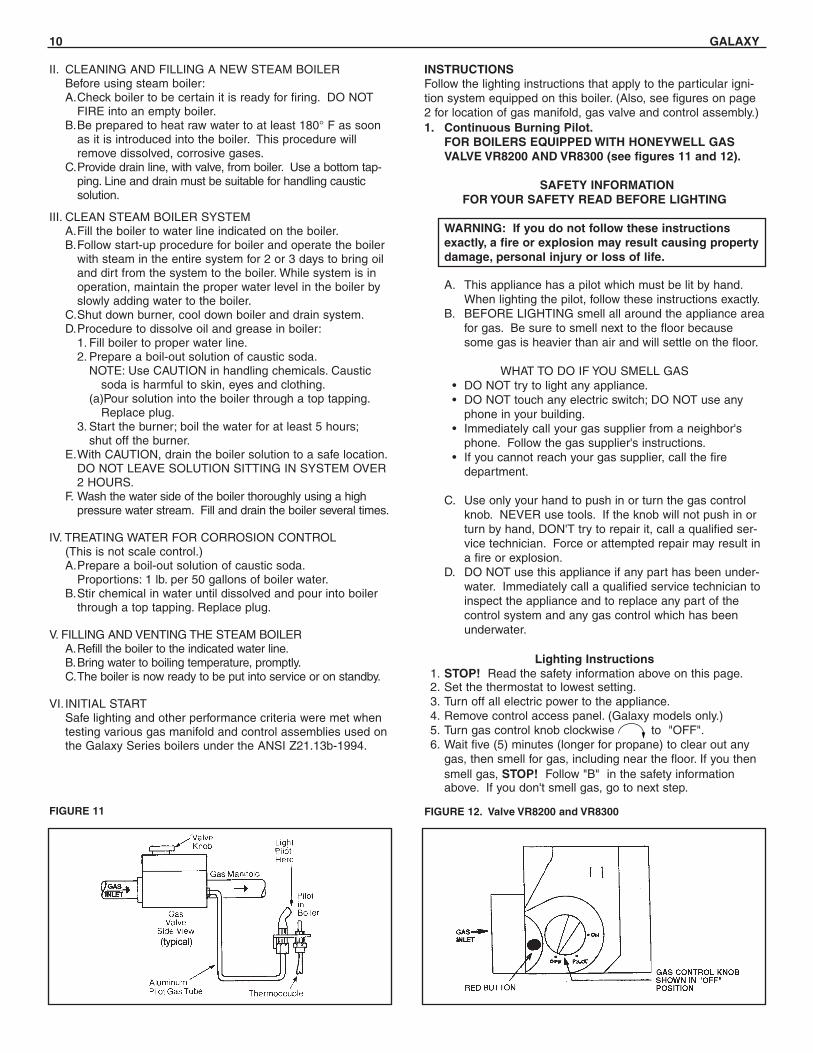
INSTRUCTIONSFollow the lighting instructions that apply to the particular igni-tion system equipped on this boiler. (Also, see figures on page2 for location of gas manifold, gas valve and control assembly.)1. Continuous Burning Pilot.
FOR BOILERS EQUIPPED WITH HONEYWELL GASVALVE VR8200 AND VR8300 (see figures 11 and 12).
SAFETY INFORMATIONFOR YOUR SAFETY READ BEFORE LIGHTING
WARNING: If you do not follow these instructionsexactly, a fire or explosion may result causing propertydamage, personal injury or loss of life.
A. This appliance has a pilot which must be lit by hand.When lighting the pilot, follow these instructions exactly.
B. BEFORE LIGHTING smell all around the appliance areafor gas. Be sure to smell next to the floor becausesome gas is heavier than air and will settle on the floor.
WHAT TO DO IF YOU SMELL GAS• DO NOT try to light any appliance.• DO NOT touch any electric switch; DO NOT use any
phone in your building.• Immediately call your gas supplier from a neighbor's
phone. Follow the gas supplier's instructions.• If you cannot reach your gas supplier, call the fire
department.
C. Use only your hand to push in or turn the gas controlknob. NEVER use tools. If the knob will not push in orturn by hand, DON'T try to repair it, call a qualified ser-vice technician. Force or attempted repair may result ina fire or explosion.
D. DO NOT use this appliance if any part has been under-water. Immediately call a qualified service technician toinspect the appliance and to replace any part of thecontrol system and any gas control which has beenunderwater.
Lighting Instructions1. STOP! Read the safety information above on this page.2. Set the thermostat to lowest setting.3. Turn off all electric power to the appliance.4. Remove control access panel. (Galaxy models only.)5. Turn gas control knob clockwise to "OFF".6. Wait five (5) minutes (longer for propane) to clear out any
gas, then smell for gas, including near the floor. If you thensmell gas, STOP! Follow "B" in the safety informationabove. If you don't smell gas, go to next step.
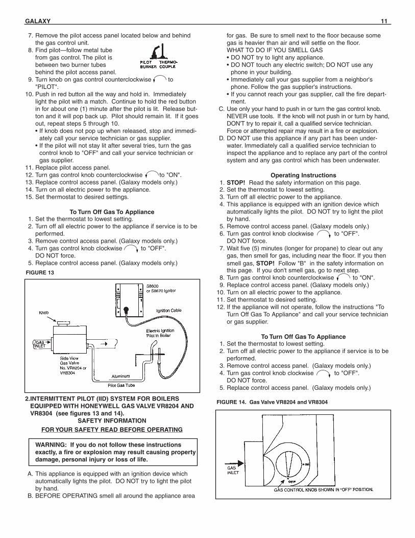
2.INTERMITTENT PILOT (IID) SYSTEM FOR BOILERSEQUIPPED WITH HONEYWELL GAS VALVE VR8204 ANDVR8304 (see figures 13 and 14).
SAFETY INFORMATIONFOR YOUR SAFETY READ BEFORE OPERATING
WARNING: If you do not follow these instructionsexactly, a fire or explosion may result causing propertydamage, personal injury or loss of life.
A. This appliance is equipped with an ignition device whichautomatically lights the pilot. DO NOT try to light the pilotby hand.
B. BEFORE OPERATING smell all around the appliance area
GALAXY 11
7. Remove the pilot access panel located below and behindthe gas control unit.
8. Find pilot—follow metal tube from gas control. The pilot is between two burner tubes behind the pilot access panel.
9. Turn knob on gas control counterclockwise to "PILOT".
10. Push in red button all the way and hold in. Immediatelylight the pilot with a match. Continue to hold the red buttonin for about one (1) minute after the pilot is lit. Release but-ton and it will pop back up. Pilot should remain lit. If it goesout, repeat steps 5 through 10.• If knob does not pop up when released, stop and immedi-
ately call your service technician or gas supplier.• If the pilot will not stay lit after several tries, turn the gas
control knob to "OFF" and call your service technician orgas supplier.
11. Replace pilot access panel.12. Turn gas control knob counterclockwise to "ON".13. Replace control access panel. (Galaxy models only.)14. Turn on all electric power to the appliance.15. Set thermostat to desired settings.
To Turn Off Gas To Appliance1. Set the thermostat to lowest setting.2. Turn off all electric power to the appliance if service is to be
performed.3. Remove control access panel. (Galaxy models only.)4. Turn gas control knob clockwise to "OFF".
DO NOT force.5. Replace control access panel. (Galaxy models only.)
FIGURE 13
FIGURE 14. Gas Valve VR8204 and VR8304
for gas. Be sure to smell next to the floor because somegas is heavier than air and will settle on the floor.WHAT TO DO IF YOU SMELL GAS• DO NOT try to light any appliance.• DO NOT touch any electric switch; DO NOT use any
phone in your building.• Immediately call your gas supplier from a neighbor's
phone. Follow the gas supplier's instructions.• If you cannot reach your gas supplier, call the fire depart-
ment.C. Use only your hand to push in or turn the gas control knob.
NEVER use tools. If the knob will not push in or turn by hand,DON'T try to repair it, call a qualified service technician.Force or attempted repair may result in a fire or explosion.
D. DO NOT use this appliance if any part has been under-water. Immediately call a qualified service technician toinspect the appliance and to replace any part of the controlsystem and any gas control which has been underwater.
Operating Instructions1. STOP! Read the safety information on this page.2. Set the thermostat to lowest setting.3. Turn off all electric power to the appliance.4. This appliance is equipped with an ignition device which
automatically lights the pilot. DO NOT try to light the pilotby hand.
5. Remove control access panel. (Galaxy models only.)6. Turn gas control knob clockwise to "OFF".
DO NOT force.7. Wait five (5) minutes (longer for propane) to clear out any
gas, then smell for gas, including near the floor. If you thensmell gas, STOP! Follow "B" in the safety information onthis page. If you don't smell gas, go to next step.
8. Turn gas control knob counterclockwise to "ON".9. Replace control access panel. (Galaxy models only.)
10. Turn on all electric power to the appliance.11. Set thermostat to desired setting.12. If the appliance will not operate, follow the instructions "To
Turn Off Gas To Appliance" and call your service technicianor gas supplier.
To Turn Off Gas To Appliance1. Set the thermostat to lowest setting.2. Turn off all electric power to the appliance if service is to be
performed.3. Remove control access panel. (Galaxy models only.)4. Turn gas control knob clockwise to "OFF".
DO NOT force.5. Replace control access panel. (Galaxy models only.)
12 GALAXY
VII.BURNER ADJUSTMENTA.Adjust gas input rate:
1. Consult gas supplier for heating value of gas (Btu/cu.ft.).2. Set thermostat high enough so that boiler will remain on
while checking rate.3. Measure manifold pressure at 1/8" tapping. Correct
manifold pressure for gas used is printed on boiler rat-ing plate. NOTE: Gas pressure may be adjusted byturning pressure regulator screw on combination gasvalve (Turn clockwise to increase pressure, counter-clockwise to decrease pressure).a. Input for PROPANE is approximately at rating shown
on rating plate when manifold pressure is 9-1/2" watercolumn.
b. Input for NATURAL GAS is approximately at ratingwhen manifold pressure is 3-1/2" water column, butshould be checked on the gas meter:Btuh Input = Btuh/cu. ft. x cu. ft. metered in 3 minutes
x 20Example #1:For 1000 Btu/cu. ft. gas, this becomes:Btuh Input = cu. ft. metered in 3 minutes x 1000
Btu/cu.ft. x 20 Example #2:For 1050 Btu/cu. ft. gas, this becomes:Btuh Input = cu. ft. metered in 3 minutes x 1050
Btu/cu.ft. x 20 4. The higher* heating value of gas varies substantially for
different localities. Consult with Slant/Fin’s TechnicalService Dept. for re-orificing procedures if any of the fol-lowing apply:a. Boiler (burner) is overfiring. CAUTION! National Fuel
Gas Code (ANSI Z223.1-latest edition) does NOTpermit firing at a higher input rate than the input rateindicated on the boiler rating plate in order to avoidhazardous conditions such as explosion or carbonmonoxide poisoning.
b. Poor higher* heating value of gas is causing the actu-al input to be substantially lower than the rating plateindication.* “Higher heating value” of gas is commonly known as “heating
value”
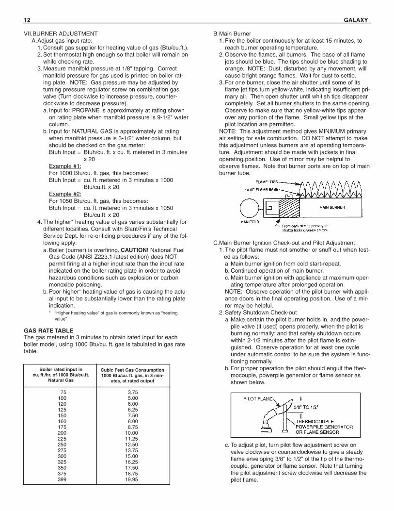
GAS RATE TABLEThe gas metered in 3 minutes to obtain rated input for eachboiler model, using 1000 Btu/cu. ft. gas is tabulated in gas ratetable.
B.Main Burner1. Fire the boiler continuously for at least 15 minutes, to
reach burner operating temperature.2. Observe the flames, all burners. The base of all flame
jets should be blue. The tips should be blue shading toorange. NOTE: Dust, disturbed by any movement, willcause bright orange flames. Wait for dust to settle.
3. For one burner, close the air shutter until some of itsflame jet tips turn yellow-white, indicating insufficient pri-mary air. Then open shutter until whitish tips disappearcompletely. Set all burner shutters to the same opening.Observe to make sure that no yellow-white tips appearover any portion of the flame. Small yellow tips at thepilot location are permitted.
NOTE: This adjustment method gives MINIMUM primaryair setting for safe combustion. DO NOT attempt to makethis adjustment unless burners are at operating tempera-ture. Adjustment should be made with jackets in finaloperating position. Use of mirror may be helpful toobserve flames. Note that burner ports are on top of mainburner tube.
C.Main Burner Ignition Check-out and Pilot Adjustment1. The pilot flame must not smother or snuff out when test-
ed as follows:a. Main burner ignition from cold start-repeat.b. Continued operation of main burner.c. Main burner ignition with appliance at maximum oper-
ating temperature after prolonged operation.NOTE: Observe operation of the pilot burner with appli-ance doors in the final operating position. Use of a mir-ror may be helpful.
2. Safety Shutdown Check-outa. Make certain the pilot burner holds in, and the power-
pile valve (if used) opens properly, when the pilot isburning normally; and that safety shutdown occurswithin 2-1/2 minutes after the pilot flame is extin-guished. Observe operation for at least one cycleunder automatic control to be sure the system is func-tioning normally.
b. For proper operation the pilot should engulf the ther-mocouple, powerpile generator or flame sensor asshown below.
c. To adjust pilot, turn pilot flow adjustment screw onvalve clockwise or counterclockwise to give a steadyflame enveloping 3/8" to 1/2" of the tip of the thermo-couple, generator or flame sensor. Note that turningthe pilot adjustment screw clockwise will decrease thepilot flame.
75 3.75100 5.00120 6.00125 6.25150 7.50160 8.00175 8.75200 10.00225 11.25250 12.50275 13.75300 15.00325 16.25350 17.50375 18.75399 19.95
Boiler rated input incu. ft./hr. of 1000 Btu/cu.ft.
Natural Gas
Cubic Feet Gas Consumption1000 Btu/cu. ft. gas, in 3 min-
utes, at rated output

GALAXY 13
d. Check safety shutdown of gas valve by following proce-dure outlined "CARE AND MAINTENANCE" section.
VIII. CONTROLS, SAFETY CHECKCheck all safety controls not previously mentioned. Also,follow directions in "CARE AND MAINTENANCE" section,paragraphs IV through VII.
These boilers are equipped with both a draft hood blockedvent safety switch and a rollout safety switch. The blockedvent safety switch is located on the draft hood flue stack.This is a manual reset control used to prevent excessivespillage of flue gases from the draft hood. The rollout safetyswitch is a single use (one time) thermal fuse to prevent theboiler from operating if flue passages are blocked. If eitherof these devices shut down the burners, follow instructionsin the section "To Turn Off Gas To Appliance" and call yourservice technician or gas supplier.
LOW WATER CUT-OFF CHECK-OUTA. Electronic Probe Type Low Water Cut-off. If this boiler is fac-
tory equipped with an electronic probe type low water cut-off, operation of cut-off should be checked at least twice ayear as follows.
1. While boiler is running, drain down boiler water slowlythrough boiler drain cock shown on page 7, just until lightgoes on. Boiler should shut down 90 seconds after lightgoes on.
2. Be sure that it is the low water cut-off and not the roomthermostat, pressure cut-out, energy cut-off or other con-trol that has shut off the burner.
3. Refill the boiler and repeat test.
4. Refill the boiler and reset controls for normal operation.
B. Float type low water cut-off. If this boiler is factoryequipped with a McDonnell & Miller float type low watercut-off, the low water cut-off must be blowndown (flushed), at least once a week.
1. CAUTION: When flushing float type low water cut-offcontrol, hot water and steam will flow out the blow down valve. Blow down valve is illustrated on page 5.
SPECIAL FLUSHING INSTRUCTIONS
Installation of new boiler may break loose a heavy accu-mulation of sediment and scale from old piping and radia-tors. It is extremely important to blow down yourMcDonnell cut-off more frequently the first week.
First week — 3 times
Thereafter — at least once a week
2. As boiler water circulates through the float chamber, dirtor other sediment may be deposited. This chamber isextra deep. But the only sure way to keep any accumula-tion from interfering with float action is to "blow down," orflush out, the control once a week.
Do it while boiler is in operation. First note water level ingauge glass. Open blow-off valve at bottom of control;water will pour out, flushing away sediment. Drain untilwater is clear—about a pail—then close valve. If level ingauge glass has dropped, add water to boiler to restorelevel.
3. NOTE: Opening blow-off valve checks cut-off operationtoo. As float drops with falling water level, burner will stop.After valve is closed and normal operating conditionsrestored, burner will resume firing.
4. Be sure that it is the low water cut-off and not the roomthermostat, pressure cut-out, energy cut-off or other con-trol that has shut off the burner.
PRESSURE CONTROL CHECK-OUTA. Check burner to be certain it is ready for firing. DO NOT
FIRE into an empty boiler.
B. Set thermostat high enough for boiler to make steam. Setthe pressure control down to its lowest setting. As the boilerstarts to produce steam, the steam pressure will start tobuild. The burner will shut off when the steam pressureexceeds the pressure setting (plus differential if the controlhas this feature).
C. Adjust the pressure control to a higher setting. The highersetting should be above the steam pressure in the boiler.This should turn the burner back on.
D. Reset the pressure control as needed for the system. Thepressure control should be checked out at least twice a year.
Steam Controls Installation InstructionsSteam kit components for Galaxy packaged models are packedas follows:1. Low water cut-off control, electric, installed.2. Pressure gauge.3. High pressure limit control.4. Water level gauge.5. Fittings.6. Instruction sheet and assembly drawing.7. Steam safety valve and 3/4" street coupling.8. Drain cock.Assembly above components exactly as shown.Two 1/2" tappings are on right side of boiler for this assembly.Two holes are pre-punched in jackets.
Steam controls assembly

14 GALAXY
Replacement of Steam BoilersAnytime an older steam boiler is removed from the heating sys-tem and replaced with a new boiler, there are certain conditionsthat have to be examined on the heating system.
1. Steam systems have a tendency to develop scale inside thewet return lines and the boiler. The older the system thegreater the accumulation of scale that can exist inside thepiping. Therefore, it is necessary when replacing a steamboiler to check the piping for blockage or restrictions. Cleanor replace the piping as required. (See special flushinginstructions page 13.)
2. Replace all buried wet return lines.
3. All equipment (air vents, radiation equipment, etc.) in thesteam heating system should be checked for proper opera-tion. All piping should be checked for proper pitch.
4. It is good engineering practice to repack or tighten the pack-ing nuts on all valves in the heating system.
BLOWING OFF A LOW PRESSURE STEAM BOILER
1. MODELS THAT HAVE NO TANKLESS HEATER OR NOPROVISION FOR HEATERA.Those models without tankless heaters or provision for
tankless heaters have a skimmer giving the advantages ofa surface blow pipe, that has been built into the casting toinsure rapid skimming of oil and grease through a 3/4"N.P.T. tapping located on the right hand jacket side panel,8-9/16" from the top and 13-1/4" from the front of the boil-er (see Figure A).
B.Turn off electrical power supply to boiler. Allow boiler tocool down and steam pressure to reduce to zero beforeremoving skimmer tapping plug. Check for steam pressureby testing the pop safety valve. Keep your hands and allparts of your body away from the discharge end of thesafety valve. Drain boiler down one to two inches belowskimmer tapping. There will be water in the skimmertrough. The water might be hot. Remove skimmer plugslowly and carefully. Install 3/4" skimmer valve, elbow andlength of pipe and place a bucket underneath the openend of the pipe. Cover bucket with a piece of cloth.
C.Fill boiler slowly until water level is two inches from top ofgauge glass. (This is the starting water level for skimming
FIGURE ARight side view of Galaxy models that are NOT equippedwith or DO NOT have provisions for tankless heaters.
FIGURE BLeft side view of Galaxy models that are equipped with orhave provisions for tankless heaters.
only.) Fire boiler to produce steam. If the system is heavilyladen with oil, it may be difficult to obtain much more thana pound or so of pressure. Set the pressure control atabout 7 psi. The higher the steam pressure you can use,the better and faster the cleaning.
D.As a steam develops, open the SKIMMER drain valve withcaution to skim the oil and film from the top of the water.DO NOT open the boiler drain valve. Close the skimmerdrain valve when the water level drops to about 5" fromthe top of the gauge glass. The water may stop before thelevel drops to 5" below the top of the glass. Refill boileruntil water level is again two inches from the top of thegauge glass.
E.Repeat (D) above until all film is skimmed off and thewater settles to a desired normal movement. Add makeupfresh water to the boiler as described in (D) above duringthe blow-off operation to maintain the proper skimmingwater level in the vessel. Empty bucket frequently in orderto see the difference in water cleanliness.
F. When surging has stopped and water is clean, and no filmcan be seen floating in the bucket, shut off boiler, draindown to level of skimmer tapping, remove valve, plugskimmer tapping and refill the boiler to the normal operat-ing water (25-1/2" from the bottom of the boiler—seeFigure A below). Check the pop safety valve for properoperation.
G.The entire process may have to be repeated over a periodof a few days on extremely fouled systems.
2. MODELS WITH TANKLESS HEATER OR WITH TANKLESSHEATER PLATES ONLY.A.Turn off electrical power supply to boiler. Allow boiler to
cool down and allow pressure to reduce to zero beforeattempting removal of components. Check for steam pres-sure by testing safety valve. Keep your hands and bodyaway from the discharge end of the valve. Remove popsafety valve and re-pipe boiler as shown in Figure Bbelow, making sure to reinstall pop safety valve on tee tocomplete the blow off connection.
B.Connect a length of pipe to the elbow and place a bucketunderneath the open end of the pipe, cover bucket with apiece of cloth.

GALAXY 15
C.Open the SKIMMER drain valve with caution. DO NOTopen the boiler drain valve. Fill the boiler slowly untilwater begins to seep into the bucket from the skimmerdrain blow-off connection. Fire the boiler. Allow water toheat up while water seeps into the bucket. Maintain thatwater level necessary just to be able to continue skim-ming. Continue until water is clean and no oil can be seenfloating in the bucket. Empty bucket frequently in order tosee if the water is clean.
D.Repeat this process until all film is skimmed off, lower thewater level to 25-1/2" from the bottom of the boiler (seeFigure B). When all surging has stopped, turn off the boil-er, remove skimmer valve and plug the tee. Check the popsafety valve for proper operation.
E.The entire process may have to be repeated over a periodof a few days on extremely fouled systems.
3. CLEANING PIPING SYSTEMA.To clean piping system, open all valves at the heating ele-
ments, after getting up a good head of steam, shut theboiler down and allow the condensate to return to the boil-er. The condensate will carry the oil film with it. Againblow-off the boiler. On extremely fouled systems, it mayrequire several visits over a period of a few days to cleanthe system.
B.When steam only (no water) is released through the handvalve, the boiler will not surge or flood.
CARE AND MAINTENANCEWARNING: THE FLOW OF COMBUSTION AND VENTILAT-ING AIR TO THE BOILER SHOULD NOT BE OBSTRUCTED.
This section must be brought to the attention of the owner bythe installer so that the owner can make the necessaryarrangements with a qualified service agency for the periodiccare and maintenance of this boiler. The installer must informthe owner that the gas supplier can recommend a number ofqualified service agencies. The installer must also inform theowner that the lack of proper care and maintenance of thisboiler and any fuel burning equipment may result in a haz-ardous condition.I. GENERAL MAINTENANCE (Refer also to User's
Information Manual)These operations are recommended to be performed at reg-ular intervals:A.BOILER HEATING SURFACES: clean off all coatings
found.B.BOILER CONTROLS: check contacts, settings, correct
functioning.C.PIPING: check piping and accessories for leaks.D.CHIMNEY and BREECHING: check for obstructions and
leaks.E.BOILER ROOM AIR SUPPLY: check air vents for contin-
ued POSITIVE supply of air as required. Air needs aregreatest in cold weather. Air vents must be open and freeof obstruction.
F. WATER SYSTEM: check1. System to be full of water, and pressure to remain sta-
ble at correct setting on gauge.2. Air-control system: noise and air binding in radiation
should not occur.3. Water lines: slightest leaks should be corrected.4. Low water cut-off, for operation (see instructions fur-
nished with unit).
II. WATER LEVEL CHECK DURING HEATING SEASON:A.Check water level regularly and add water slowly to sys-
tem when needed. If much water is added, venting maybe necessary.
B.Regular loss of water from water boiler system may indi-cate either a system leak, or a faulty air-control system, ora faulty automatic fill valve.
III. ANNUAL INSPECTION AND CLEANING:A.It is important that this boiler be inspected by a competent
serviceperson to help insure safe and reliable operation.B.Check for gas leaks from valve and gas piping to burners
and pilot. If leaks are found, repair or replace as required.C.This inspection should include:
1. Controls check. See SAFETY CHECK, IV. on page 16.2. Recheck of input gas rate to burners. See "Initial Start"
paragraph in "Operating Instructions" section.3. Re-adjusting for best flame characteristics of main flame
and pilot(s).See "Initial Start" paragraph in "Operating Instructions"section and see "Burner Adjustment" section.
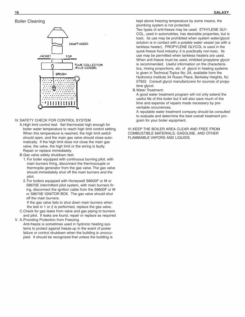
4. Burner and boiler flue passage cleanliness: BURNERAND FLUE CLEANING (see sketch). It is suggestedthat paper be placed on burners to collect any foreignmaterial in cleaning flues.
5. Remove draft hood, jacket top and flue cover.6. Use wire brush to clean flueways.7. Replace flue cover and re-seal with furnace cement.
Replace jacket top and draft hood and reconnect tosmoke pipe, using screws. Remove and dispose ofpaper and accumulated material.
8. If burner surfaces are not clean, or if uneven flame indi-cates plugged burner ports, remove and clean burners.
NOTE—TO REMOVE BURNERS:a. Remove holding wire clip at orifice.b. Disconnect pilot at pilot mount, or disconnect thermocou-
ple and pilot gas line at gas valve, before removing burn-ers next to pilot.
c. Lift rear of burner and remove burner from orifice.d. Clean and replace burners* and pilot. Adjust burners as
described on page 12.
* To clean burners run a clean flue brush up the tube untilall foreign matter is removed.
WARNING:The ceramic combustion chamber in the burner boxcontains crystalline silica.Wear proper dust mask and gloves when servicingcombustion chamber or burners.Crystalline Silica has been identified as a carcino-genic or possibly carcinogenic to humans.
16 GALAXY
IV. SAFETY CHECK FOR CONTROL SYSTEMA.High limit control test: Set thermostat high enough for
boiler water temperature to reach high limit control setting.When this temperature is reached, the high limit switchshould open, and the main gas valve should close auto-matically. If the high limit does not close the main gasvalve, the valve, the high limit or the wiring is faulty.Repair or replace immediately.
B.Gas valve safety shutdown test:1. For boiler equipped with continuous burning pilot, with
main burners firing, disconnect the thermocouple orthermopile generator from the gas valve. The gas valveshould immediately shut off the main burners and thepilot.
2. For boilers equipped with Honeywell S8600F or M orS8670E intermittent pilot system, with main burners fir-ing, disconnect the ignition cable from the S8600F or Mor S8670E IGNITOR BOX. The gas valve should shutoff the main burners.If the gas valve fails to shut down main burners whenthe test in 1 or 2 is performed, replace the gas valve.
C.Check for gas leaks from valve and gas piping to burnersand pilot. If leaks are found, repair or replace as required.
V. A.Providing Protection from Freezing.Anti-freeze is sometimes used in hydronic heating sys-tems to protect against freeze-up in the event of powerfailure or control shutdown when the building is unoccu-pied. It should be recognized that unless the building is
kept above freezing temperature by some means, theplumbing system is not protected.Two types of anti-freeze may be used: ETHYLENE GLY-COL, used in automobiles, has desirable properties, but istoxic. Its use may be prohibited when system water/glycolsolution is in contact with a potable water vessel (as with atankless heater). PROPYLENE GLYCOL is used in thequick-freeze food industry; it is practically non-toxic. Itsuse may be permitted when tankless heaters are used.When anti-freeze must be used, inhibited propylene glycolis recommended. Useful information on the characteris-tics, mixing proportions, etc. of glycol in heating systemsis given in Technical Topics No. 2A, available from theHydronics Institute 34 Russo Place, Berkeley Heights, NJ07922. Consult glycol manufacturers for sources of propy-lene glycol.
B.Water Treatment:A good water treatment program will not only extend theuseful life of this boiler but it will also save much of thetime and expense of repairs made necessary by pre-ventable occurrences.A reputable water treatment company should be consultedto evaluate and determine the best overall treatment pro-gram for your boiler equipment.
VI.KEEP THE BOILER AREA CLEAR AND FREE FROMCOMBUSTIBLE MATERIALS, GASOLINE, AND OTHERFLAMMABLE VAPORS AND LIQUIDS.
Boiler Cleaning

GALAXY 17
SEQUENCE OF OPERATION FOR GALAXY BOILERS EQUIPPED WITH CONTINUOUS BURNING PILOTFOR DIAGRAMS SHOWN ON PAGE 18-21.
SEQUENCE OF OPERATION FOR GALAXY BOILERS EQUIPPED WITH HONEYWELL INTERMITTENT PILOT IGNITIONSYSTEM (IID) FOR DIAGRAMS SHOWN ON PAGES 22-24.
LIGHTED PILOT HEATS THERMOCOUPLE AND KEEPS PILOTSTAT OPEN.
HIGH-LIMIT CONTACTS CLOSED?LOW WATER CUT-OFF (WHEN USED) CONTACTS CLOSED?PRESSURE CUT-OUT (WHEN USED) CONTACTS CLOSED?
VENT DAMPER RELAY ENERGIZED.VENT DAMPER MOTOR MOVES OPEN (VENT DAMPER OPENS).
END SWITCH CLOSES.
MAIN VALVE OPERATOR OPENS.LIT PILOT IGNITES MAIN BURNERS.
IF PILOT SHOULD BLOW OUT, THERMOCOUPLE WILL SHUT OFF MAIN BURNERS.
WHEN THERMOSTAT IS SATISFIED OR WHEN HIGH LIMIT, LOW LIMIT, PRESSURE CUT-OUT, ORLOW WATER CUT-OFF CONTACTS ARE OPEN, MAIN VALVE OPERATOR CLOSES. VENT DAMPER
CLOSES. CIRCULATOR OFF. SYSTEM GOES TO STANDBY WITH LIT PILOT.
THERMOSTAT CALLSFOR HEAT
HOT WATER BOILERS EQUIPPEDWITH COMBINATION AQUASTATS:
CIRCULATOR ENERGIZESUNLESS LOW LIMIT (L8124 ONLY)
IS CALLING FOR HOT WATER
VENT DAMPER(MODELS UNDER300,000 BTU/HR.)
LOW LIMIT (FOR TANKLESS COIL)CALLS FOR HOT WATER
NO FURTHERACTION
OR
NO
YES
HIGH-LIMIT CONTACTS CLOSED?LOW WATER CUT-OFF (WHEN USED) CONTACTS CLOSED?PRESSURE CUT-OUT (WHEN USED) CONTACTS CLOSED?
VENT DAMPER RELAY ENERGIZED.VENT DAMPER MOTOR MOVES OPEN VENT DAMPER.
END SWITCH CLOSES.
IGNITION CONTROL ENERGIZED
SPARK GENERATOR MODULE POWEREDS8600F OR S8600M: IGNITION SPARK STARTS AND PILOT VALVE OPERATOR OPENS.
S8670E: IGNITION SPARK AND PILOT VALVE OPERATOR DELAYED FOR 30-70 SECONDS.
L.P. PROPANE GAS(S8600M AND S8670E)
IGNITION TRIAL CONTIN-UES FOR 90 SECONDS.AFTER TRIAL FOR IGNI-
TION, SYSTEM SHUTS OFF.AFTER 5 MINUTES MOD-ULE RE-INSTATES TRIALFOR IGNITION. IF PILOT
FLAME NOT ESTABLISHED,IGNITION TRIAL, SYSTEM
SHUT-OFF AND 5 MINUTESWAIT SEQUENCE REPEATS
CONTINUOUSLY.
NATURAL GAS (S8600F)IGNITION SPARK CON-TINUES. PILOT VALVE
REMAINS OPEN UNTILSYSTEM IS RESET.
SPARK GENERATOR OFF. MAIN VALVE OPERATOR OPENS. MODULE MONITORS PILOT FLAME.
THERMOSTAT CALLSFOR HEAT
HOT WATER BOILERS EQUIPPEDWITH COMBINATION AQUASTATS:
CIRCULATOR ENERGIZESUNLESS LOW LIMIT (L8124 ONLY)
IS CALLING FOR HOT WATER
MODELS WITHVENT DAMPERS
LOW LIMIT (FOR TANKLESS COIL)CALLS FOR HOT WATER
THE PILOT FLAME ESTABLISHED?
WHEN THERMOSTAT IS SATISFIED OR WHEN HIGH LIMIT, LOW LIMIT, PRESSURE CUT-OUT, OR LOW WATER CUT-OFF CON-TACTS ARE OPEN, VALVE OPERATORS CLOSE, VENT DAMPER CLOSES. CIRCULATOR OFF. SYSTEM GOES TO STANDBY.
NO FURTHERACTION
OR
NO
NONO
YES
YES

18 GALAXY
WIRING DIAGRAMS FOR HOT WATER BOILERS WITH INPUT UNDER 300,000 BTU/HRMODELS WITH CONTINUOUS PILOT AND VENT DAMPER
CAUTION: Label all wires prior to disconnection when servicing control.Wiring errors can cause improper and dangerous operation. “Verify proper operation after servicing.”

GALAXY 19
WIRING DIAGRAMS FOR HOT WATER BOILERS WITH INPUT OF 300,000 BTU/HRMODELS WITH CONTINUOUS PILOT AND OPTIONAL VENT DAMPER
CAUTION: Label all wires prior to disconnection when servicing control.Wiring errors can cause improper and dangerous operation. “Verify proper operation after servicing.”
20 GALAXY
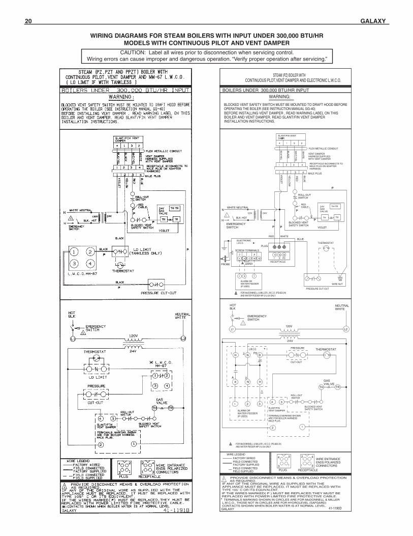
WIRING DIAGRAMS FOR STEAM BOILERS WITH INPUT UNDER 300,000 BTU/HRMODELS WITH CONTINUOUS PILOT AND VENT DAMPER
ALARM ORWATER FEEDER(IF USED)
132
N H
2
C W B
A
: FOR McDONNNELL & MILLER L.W.C.O. (PS-802-24) AND WATER FEEDER WF-2-U-24 ONLY
: FOR McDONNNELL & MILLER L.W.C.O. (PS-802-24) AND WATER FEEDER WF-2-U-24 ONLY
41-1190D
ALARM ORWATER FEEDER(IF USED)
P
THERMOSTAT
WIRE NUT
PRESSURE CUT-OUT
IF THE WIRES MARKED( P ) MUST BE REPLACED,THEY MUST BEREPLACED WITH POWER LIMITED FIRE PROTECTIVE CABLE.
24V
SLANT/FINVENT DAMPER
TERMINALS MARKING SHOWNARE FOR BOILER HARNESSMALE PLUG.
BLK. HOT
120V
VIOLET
BLOCKED VENTSAFETY SWITCH
P
P
P P
TERMINALS MARKING SHOWN IN CIRCLES ARE FOR McDONNELL & MILLERL.W.C.O., THOSE NOT IN CIRCLES ARE FOR HYDROLEVEL (SAFGARD)CONTACTS SHOWN WHEN BOILER WATER IS AT NORMAL LEVEL.
THERMOSTATPRESSURE
CUT-OUT
*
L2
NEUTRALWHITE
BLUE
ROLL-OUTSWITCH
VIO
LET
YE
LLO
W
RE
D
BLU
E
FLEX METALLIC CONDUIT
MALE PLUG
WHITERED
PLUG
SCREW TERMINALS
PROBE
WHITE NEUTRAL
EMERGENCYSWITCH
ELECTRONICL.W.C.O.
N
H
L1
*L.W.C.O.
P221
321
HNW
BNH
1
EMERGENCYSWITCH
HOTBLK
P221
2A
STEAM (PZ) BOILER WITH CONTINUOUS PLOT,VENT DAMPER AND ELECTRONIC L.W.C.O.
RECEPTACLE
BNH
BLOCKED VENT SAFETY SWITCH MUST BE MOUNTED TO DRAFT HOOD BEFOREOPERATING THE BOILER (SEE INSTRUCTION MANUAL GG-40)BEFORE INSTALLING VENT DAMPER , READ WARNING LABEL ON THISBOILER AND VENT DAMPER. READ SLANT/FIN VENT DAMPERINSTALLATION INSTRUCTIONS.
214
GALAXY
*
BLK
/YE
L
BLA
CK
WH
T/Y
EL
WH
ITE
SLANT/FIN VENTDAMPER
BLOCKED VENTSAFETY SWITCH
BOILERS UNDER 300,000 BTU/HR INPUT
IF ANY OF THE ORIGINAL WIRE AS SUPPLIED WITH THEAPPLIANCE MUST BE REPLACED, IT MUST BE REPLACED WITHTYPE 105˚ C OR ITS EQUIVALENT.
PROVIDE DISCONNECT MEANS & OVERLOAD PROTECTION AS REQUIRED.
WARNING:
PLUG RECEPTACLE
1
WIRE ENTRANCEENDS POLARIZEDCONNECTORS
2
3
2
1 3
4
1
4WIRE LEGEND
FACTORY WIREDFIELD CONNECTEDFACTORY SUPPLIEDFIELD CONNECTEDFIELD SUPPLIED
24V
120V
ROLL-OUT SWITCH
4 3
12
RECEPTACLE B(CONNECTS TOMALE PLUG ON ADAPTERHARNESS)
VENT DAMPERHARNESS SUPPLIEDWITH VENT DAMPER
REDCABLE
1 2 3 4
3
1 2 3 4
1
24VGASVALVE
TH TR
TH-TR
TH
GASVALVE
TR
JUMPER
CAUTION: Label all wires prior to disconnection when servicing control.Wiring errors can cause improper and dangerous operation. “Verify proper operation after servicing.”

GALAXY 21
WIRING DIAGRAMS FOR STEAM BOILERS WITH INPUT OF 300,000 BTU/HRMODELS WITH CONTINUOUS PILOT AND OPTIONAL VENT DAMPER
: FOR McDONNNELL & MILLER L.W.C.O. (PS-802-24) AND WATER FEEDER WF-2-U-24 ONLY
N H
: FOR McDONNNELL & MILLER L.W.C.O. (PS-802-24) AND WATER FEEDER WF-2-U-24 ONLY
2
C W B
A
JUMPER
STEAM (PZ) BOILER WITH CONTINUOUS PLOT,OPTIONAL VENT DAMPER AND ELECTRONICL.W.C.O.
BOILERS WITH 300,000 BTU/HR INPUTWARNING:
OPTIONAL VENT DAMPER
SLANT/FINVENT DAMPER
RECECPTACLE A
RED
4321
214
BLK
/YE
L
BLA
CK
WH
T/Y
EL
WH
ITE
3
1 2 3 4
RECEPTACLE B(CONNECTS TOMALE PLUG ON ADAPTERHARNESS)
VENT DAMPERHARNESS SUPPLIEDWITH VENT DAMPER
FLEX METALLIC CONDUIT
41-1263 A
ALARM ORWATER FEEDER(IF USED)
P
THERMOSTAT
WIRE NUT
PRESSURE CUT-OUT
IF THE WIRES MARKED( ) MUST BE REPLACED,THEY MUST BEREPLACED WITH POWER LIMITED FIRE PROTECTIVE CABLE.
24V
SLANT/FINVENT DAMPER
TERMINALS MARKING SHOWNARE FOR BOILER HARNESSMALE PLUG.
BLK. HOT
120V
VIOLET
BLOCKED VENTSAFETY SWITCH
P
P
P
P
TERMINALS MARKING SHOWN IN CIRCLES ARE FOR McDONNELL & MILLERL.W.C.O., THOSE NOT IN CIRCLES ARE FOR HYDROLEVEL (SAFGARD)CONTACTS SHOWN WHEN BOILER WATER IS AT NORMAL LEVEL.
THERMOSTATPRESSURE
CUT-OUT
*L2
NEUTRALWHITE
BLUE
ROLL-OUTSWITCH
VIO
LET
YE
LL
OW
RE
D
BLU
E
MALE PLUG
WHITERED
PLUG
SCREW TERMINALS
PROBE
WHITE NEUTRAL
EMERGENCYSWITCH
ELECTRONICL.W.C.O.
N
H
L1
*L.W.C.O.
P221
321
HNW
BNH
1
EMERGENCYSWITCH
HOTBLK
P221
2A
ALARM ORWATER FEEDER(IF USED)
132
RECEPTACLE
BNH
BLOCKED VENT SAFETY SWITCH MUST BE MOUNTED TO DRAFT HOOD BEFOREOPERATING THE BOILER (SEE INSTRUCTION MANUAL GG-40)BEFORE INSTALLING VENT DAMPER , READ WARNING LABEL ON THISBOILER AND VENT DAMPER. READ SLANT/FIN VENT DAMPERINSTALLATION INSTRUCTIONS.
GALAXY
*
BLOCKED VENTSAFETY SWITCH
IF ANY OF THE ORIGINAL WIRE AS SUPPLIED WITH THEAPPLIANCE MUST BE REPLACED, IT MUST BE REPLACED WITHTYPE 105˚ C OR ITS EQUIVALENT.
PROVIDE DISCONNECT MEANS & OVERLOAD PROTECTION AS REQUIRED.
PLUG RECEPTACLE
1
WIRE ENTRANCEENDS POLARIZEDCONNECTORS
2
3
2
1 3
4
1
4WIRE LEGEND
FACTORY WIREDFIELD CONNECTEDFACTORY SUPPLIEDFIELD CONNECTEDFIELD SUPPLIED
24V
120V
ROLL-OUT SWITCH
4 3
12
REDCABLE
1 2 3 4
1
24VGASVALVE
TH TR
TH-TR
TH
GASVALVE
TR
CAUTION: Label all wires prior to disconnection when servicing control.Wiring errors can cause improper and dangerous operation. “Verify proper operation after servicing.”

22 GALAXY
WIRING DIAGRAMS FOR HOT WATER BOILERSWITH INPUT UNDER 300,000 BTU/HR
MODELS WITH IID (INTERMITTENT IGNITION SYSTEM)AND VENT DAMPER
WIRING DIAGRAMS FOR STEAM BOILERSWITH INPUT UNDER 300,000 BTU/HR
MODELS WITH IID (INTERMITTENT IGNITION SYSTEM)AND VENT DAMPER
STEAM (PZ,PZT AND PPZT) BOILER WITH 24V HONEYWELLINTERMITTENT IGNITION, VENT DAMPER ANDMM-67 L.W.C.O. ( LO LIMIT IF W/ TANKLESS )
41-1194 E
BLOCKED VENT SAFETY SWITCH MUST BE MOUNTED TO DRAFT HOOD BEFOREOPERATING THE BOILER (SEE INSTRUCTION MANUAL GALAXY GG-40)
GALAXY
IF THE WIRES MARKED ( ) MUST BE REPLACED,THEY MUST BEREPLACED WITH POWER LIMITED FIRE PROTECTIVE CABLE.
P
NEUTRAL WHITE
: CONTACTS SHOWN WHEN BOILERWATER IS AT NORMAL LEVEL.
MVPV
PV
MV
NEUTRALWHITE
MM-67 L.W.C.0.
THERMOSTAT
BLK
BLK
S8600OR S8670PILOTLIGHTER
PRESSURE CUT-OUT
LOW LIMIT
RED
BLOCKED VENTSAFETYSWITCHES
BLK
S8600 OR S867024V120V
FOR PROPANE USE S8600M OR S8670E, FOR NATURAL GAS S8600F,S8600M OR S8670E.
SLANT/FINVENT DAMPER
TERMINALS MARKING SHOWNARE FOR BOILER HARNESSMALE PLUG.
RED
VIOLET
THERMOSTAT 24V
LOW LIMIT(IF USED)
P
P
P
P
2
43
1
MAINVALVECOIL
PILOTVALVECOIL
MV
PV
MV/PV
L1 L2
24V(GND)
SPARK
BLACK
4
MM-67L.W.C.0.
EMERGENCYSWITCH
H
N
HOT BLK.1
43
21
ROLL-OUT AND BLOCKEDVENT SAFETY SWITCHES
ROLL-OUT AND
PILOT GAS
214
BEFORE INSTALLING VENT DAMPER , READ WARNING LABEL ON THISBOILER AND VENT DAMPER. READ SLANT/FIN VENT DAMPERINSTALLATION INSTRUCTIONS.
GND
BLK
/YE
L
BLA
CK
WH
T/Y
EL
WH
ITE
IF ANY OF THE ORIGINAL WIRE AS SUPPLIED WITH THEAPPLIANCE MUST BE REPLACED, IT MUST BE REPLACED WITHTYPE 105˚ C OR ITS EQUIVALENT.
PROVIDE DISCONNECT MEANS & OVERLOAD PROTECTION AS REQUIRED.
BOILERS UNDER 300,000 BTU/HR INPUT
GAS VALVE
(GND) 24V24V
GAS VALVE
MALE PLUG
SLANT/FIN VENTDAMPER
24V
ELECTRICIGNITIONPILOT
WARNING:
PLUG RECEPTACLE
1
WIRE ENTRANCEENDS POLARIZEDCONNECTORS
2
3
2
1 3
4
1
4WIRE LEGEND
FACTORY WIREDFIELD CONNECTEDFACTORY SUPPLIEDFIELD CONNECTEDFIELD SUPPLIED
24V
120V
VIO
LET
YE
LL
OW
BLU
E
RE
D
VENT DAMPERHARNESS SUPPLIEDWITH VENT DAMPER
FLEX METALLIC CONDUIT
RECEPTACLE B(CONNECTS TOMALE PLUG ON ADAPTERHARNESS)
1 2 3 4
3
1 2 3 4
3
12
EMERGENCYSWITCH
MVPV
MVPVGND
IGNITIONCABLE
250∞C
RED
WHITE
GREEN
GND
GND(BURNER)
MV
PV
MV/PV
1
HOTBLK
PRESSURE CUT-OUT
CAUTION: Label all wires prior to disconnection when servicing control.Wiring errors can cause improper and dangerous operation. “Verify proper operation after servicing.”

GALAXY 23
WIRING DIAGRAMS FOR STEAM BOILERSWITH INPUT UNDER 300,000 BTU/HR
MODELS WITH IID (INTERMITTENT IGNITION SYSTEM)AND VENT DAMPER
WIRING DIAGRAMS FOR STEAM BOILERSWITH INPUT OF 300,000 BTU/HR OR GREATER
MODELS WITH IID (INTERMITTENT IGNITION SYSTEM)AND OPTIONAL VENT DAMPER
N H
2
C W B
A
: FOR McDONNNELL & MILLER L.W.C.O. (PS-802-24) AND WATER FEEDER WF-2-U-24 ONLY
JUMPER
WIRE NUT
41-1192 D
L2
S8600ORS8670PILOTLIGHTER
THERMOSTAT
WATER FEEDEROR ALARM(IF USED)
PRESSURE
CUT-OUT
SLANT/FINVENT DAMPER
TERMINALS MARKING SHOWNARE FOR BOILER HARNESSMALE PLUG.
MVPV
PV
MV
24V
120V
EMERGENCYSWITCH
L.W.C.O. *
321
HNW
BNHP221
2A
L11
HOTBLK
NEUTRALWHITE
GAS VALVE
GND
ROLL-OUT SWITCH
(GND) 24V24V
BLOCKED VENTSAFETY SWITCH
4 3
12
PILOTVALVECOIL
MAINVALVECOIL
MVPV
MVPVGND
BLUE
PRESSURE CUT-OUT
MALE PLUG
PLUG
*ELECTRONICL.W.C.O.
ELECTRICIGNITIONPILOT
THERMOSTAT
VIOLET
BLACK
RED
WHITE
PILOT GAS
250∞C
IGNITIONCABLE
GND(BURNER)
MV/PV
P
ALARM ORWATER FEEDER(IF USED)
HOT BLK.
120V 24V
P
P
P
P
P
P
MV MV/PV
PV
S8600 OR S8670H
N
EMERGENCYSWITCH
WHITE NEUTRAL
SPARK
GREEN
(GND)
24V
PROBE
132
RECEPTACLE
P221
BNH
RED WHITE
SCREWTERMINALS
GAS VALVE
BLOCKED VENTSAFETY SWITCH
24V
VIO
LET
YE
LLO
W
BLU
E
RE
D
REDCABLE
ROLL-OUTSWITCH
1 2 3 4
1
GND
MV
PV
TERMINALS MARKING SHOWN IN CIRCLES ARE FOR McDONNELL & MILLERL.W.C.O. THOSE NOT IN CIRCLES ARE FOR HYDROLEVEL (SAFGARD)CONTACTS SHOWN WHEN BOILER WATER IS AT NORMAL LEVEL.
IF THE WIRES MARKED( ) MUST BE REPLACED,THEY MUST BEREPLACED WITH POWER LIMITED FIRE PROTECTIVE CABLE.
IF ANY OF THE ORIGINAL WIRE AS SUPPLIED WITH THEAPPLIANCE MUST BE REPLACED, IT MUST BE REPLACED WITHTYPE 105˚ C OR ITS EQUIVALENT.
FOR PROPANE USE S8600M OR S8670E ONLY , FOR NATURAL GAS S8600F,S8600M OR S8670E.
BEFORE INSTALLING VENT DAMPER , READ WARNING LABEL ON THISBOILER AND VENT DAMPER. READ SLANT/FIN VENT DAMPERINSTALLATION INSTRUCTIONS.
STEAM ( PZ ) BOILER WITH 24V HONEYWELL INTERMITTENT IGNITION, VENT DAMPER AND ELECTRONIC L.W.C.O.
BLOCKED VENT SAFETY SWITCH MUST BE MOUNTED TO DRAFT HOOD BEFOREOPERATING THE BOILER (SEE INSTRUCTION MANUAL GG-40).
214
GALAXY
FLEX METALLIC CONDUIT
WARNING:
*
BLK
/YE
L
BLA
CK
WH
T/Y
EL
WH
ITE
SLANT/FIN VENTDAMPER
BOILERS UNDER 300,000 BTU/HR INPUT
PROVIDE DISCONNECT MEANS & OVERLOAD PROTECTION AS REQUIRED.
PLUG RECEPTACLE
1
WIRE ENTRANCEENDS POLARIZEDCONNECTORS
2
3
2
1 3
4
1
4WIRE LEGEND
FACTORY WIREDFIELD CONNECTEDFACTORY SUPPLIEDFIELD CONNECTEDFIELD SUPPLIED
RECEPTACLE B(CONNECTS TOMALE PLUG ON ADAPTERHARNESS)
VENT DAMPERHARNESS SUPPLIEDWITH VENT DAMPER
3
1 2 3 4
WIRE NUT
BLUE
PRESSURE CUT-OUT
MALE PLUG
41-1135F
S8600ORS8670PILOTLIGHTER
THERMOSTAT
WATER FEEDEROR ALARM(IF USED)
PLUG
*ELECTRONICL.W.C.O.
L2
ELECTRICIGNITIONPILOT
THERMOSTAT
VIOLET
BLACK
RED
WHITE
PILOT GAS
250∞C
IGNITIONCABLE
GND(BURNER)
MV/PV
P
ALARM ORWATER FEEDER(IF USED)
RECEPTACLE A
RED
1 2 3 4
*
TERMINALS MARKING SHOWN IN CIRCLES ARE FOR McDONNELL & MILLERL.W.C.O. THOSE NOT IN CIRCLES ARE FOR HYDROLEVEL (SAFGARD)CONTACTS SHOWN WHEN BOILER WATER IS AT NORMAL LEVEL.
IF THE WIRES MARKED( P) MUST BE REPLACED,THEY MUST BEREPLACED WITH POWER LIMITED FIRE PROTECTIVE CABLE.
BEFORE INSTALLING VENT DAMPER , READ WARNING LABEL ON THISBOILER AND VENT DAMPER. READ SLANT/FIN VENT DAMPERINSTALLATION INSTRUCTIONS.FOR PROPANE USE S8600M OR S8670E, FOR NATURAL GAS S8600F,S8600M OR S8670E.
HOT BLK.
120V 24V
PRESSURE
CUT-OUT
P
SLANT/FINVENT DAMPER
TERMINALS MARKING SHOWNARE FOR BOILER HARNESSMALE PLUG.
P
P
P
P
MVPV
PV
MV
MV MV/PV
PV
S8600 OR S8670
24V
120V
EMERGENCYSWITCH
H
N
EMERGENCYSWITCH
WHITE NEUTRAL
SPARK
L.W.C.O. *
GREEN
(GND)
24V
321
HNW
BNHP221
2A
L11
HOTBLK
NEUTRALWHITE
PROBE
132
RECEPTACLE
P221N H
2
C
BNH
RED WHITE
SCREWTERMINALS
GAS VALVE
GND
GAS VALVE
ROLL-OUT SWITCH
BLOCKED VENTSAFETY SWITCH
(GND) 24V24V
24V
VIO
LET
BLOCKED VENTSAFETY SWITCH
YE
LLO
W
BLU
E
RE
D
4 3
12
REDCABLE
ROLL-OUTSWITCH
1 2 3 4
1
PILOTVALVECOIL
MAINVALVECOIL
MVPV
MVPVGND
GND
MV
PV
RECEPTACLE B(CONNECTS TOMALE PLUG ON ADAPTERHARNESS)
OPTIONALVENT DAMPER
VENT DAMPERHARNESS SUPPLIEDWITH VENT DAMPER
FLEXMETALLICCONDUIT
STEAM ( PZ ) BOILER WITH 24V HONEYWELL INTERMITTENT IGNITION, OPTIONALVENT DAMPER AND ELECTRONIC L.W.C.O.
BLOCKED VENT SAFETY SWITCH MUST BE MOUNTED TO DRAFT HOOD BEFOREOPERATING THE BOILER (SEE INSTRUCTION MANUAL GG-40).
214
GALAXY
BOILERS WITH INPUT OF 300,000 BTU/HR OR GREATER
BLK
/YE
L
WH
T/Y
EL
BLA
CK
WH
ITE
4321
3
SLANT/FIN VENTDAMPER
WARNING:
IF ANY OF THE ORIGINAL WIRE AS SUPPLIED WITH THEAPPLIANCE MUST BE REPLACED, IT MUST BE REPLACED WITHTYPE 105˚ C OR ITS EQUIVALENT.
PROVIDE DISCONNECT MEANS & OVERLOAD PROTECTION AS REQUIRED.
PLUG RECEPTACLE
1
WIRE ENTRANCEENDS POLARIZEDCONNECTORS
2
3
2
1 3
4
1
4WIRE LEGEND
FACTORY WIREDFIELD CONNECTEDFACTORY SUPPLIEDFIELD CONNECTEDFIELD SUPPLIED
: FOR McDONNELL & MILLER L.W.C.O. (PS-802-24) AND WATER FEEDER WF-2-U-24 ONLY
W B
A
JUMPER
CAUTION: Label all wires prior to disconnection when servicing control.Wiring errors can cause improper and dangerous operation. “Verify proper operation after servicing.”

24 GALAXY
PRESURE CUT-OUT
: CONTACTS SHOWN WHEN BOILERWATER IS AT NORMAL LEVEL.
IF THE WIRES MARKED( ) MUST BE REPLACED,THEY MUST BEREPLACED WITH POWER LIMITED FIRE PROTECTIVE CABLE.
BLOCKED VENTSAFETYSWITCH
P REDRED
ROLL-OUTSWITCH
2
2
EMERGENCYSWITCH
MVPV
PV
MV
NEUTRALWHITE
MM-67 L.W.C.0.
THERMOSTAT
BLK
BLK
S8600OR S8670PILOTLIGHTER
PRESURE CUT-OUT
LOW LIMIT
BLK
S8600 OR S867024V120V
SLANT/FINVENT DAMPER
TERMINALS MARKING SHOWNARE FOR BOILER HARNESSMALE PLUG.
VIOLET
THERMOSTAT 24V
LOW LIMIT(IF USED)
P
P
P
P
P
2
43
1
MAINVALVECOIL
PILOTVALVECOIL
MV
PV
MV/PV
L1 L2
24V(GND)
SPARK
BLACK
4
MM-67L.W.C.0.
H
NWHITE NEUTRAL
HOT BLK.1
43
21
ROLL-OUT AND BLOCKEDVENT SAFETY SWITCHES
PILOT GAS
GND
GAS VALVE
(GND) 24V24V
GAS VALVE
MALE PLUG
24V
ELECTRICIGNITIONPILOT
24V
120V
YE
LLO
W
BLU
E
RE
D
1 2 3 4
3
12
EMERGENCYSWITCH
MVPV
MVPVGND
IGNITIONCABLE
250∞C
RED
WHITE
GREEN
GND
GND(BURNER)
MV
PV
MV/PV
1
HOTBLK
VIO
LET
RECEPTACLE B(CONNECTS TOMALE PLUG ON ADAPTERHARNESS)
OPTIONAL VENT DAMPER
41-1667U
FLEX METALLIC CONDUIT
FOR FIELD-WIRED CONNECTIONS, USE WIRING MATERIAL RATED FOR AT LEAST 75˚C.2
1PROVIDE DISCONNECT MEANS & OVERLOAD PROTECTION
AS REQUIRED.
FOR PROPANE USE S8600M OR S8670E ONLY, FOR NATURAL GAS S8600F,S8600M OR S8670E.
BLOCKED VENT SAFETY SWITCH MUST BE MOUNTED TO DRAFT HOOD BEFOREOPERATING THE BOILER (SEE INSTRUCTION MANUAL GG-40).
214
GALAXY
VENT DAMPERHARNESS SUPPLIEDWITH VENT DAMPER
RECEPTACLE A
BLK
/YE
L
WH
T/Y
EL
BLA
CK
WH
ITE
BOILERS WITH INPUT OF 300,000 BTU/HR OR GREATER
BEFORE INSTALLING OPTIONAL VENT DAMPER , READ WARNINGLABEL ON THIS BOILER AND VENT DAMPER. READ SLANT/FIN VENTDAMPER INSTALLATION INSTRUCTIONS.
RED
4321
3
SLANT/FIN VENTDAMPER
IF ANY OF THE ORIGINAL WIRE AS SUPPLIED WITH THEAPPLIANCE MUST BE REPLACED, IT MUST BE REPLACED WITHTYPE 105˚ C OR ITS EQUIVALENT.
WARNING:
PLUG RECEPTACLE
WIRE ENTRANCEENDS POLARIZEDCONNECTORS
2
3
2
1 3
4
1
4WIRE LEGEND
FACTORY WIREDFIELD CONNECTEDFACTORY SUPPLIEDFIELD CONNECTEDFIELD SUPPLIED
1 2 3 4
STEAM (PZ,PZT AND PPZT) BOILER WITH 24V HONEYWELLINTERMITTENT IGNITION, OPTIONAL VENT DAMPER AND MM-67 L.W.C.O. ( LO LIMIT IF W/ TANKLESS )
WIRING DIAGRAMS FOR STEAM BOILERSWITH INPUT OF 300,000 BTU/HR OR GREATER MODELS
WITH IID (INTERMITTENT IGNITION SYSTEM) ANDOPTIONAL VENT DAMPER
WIRING DIAGRAMS FOR HOT WATER BOILERSWITH INPUT OF 300,000 BTU/HR OR GREATER
MODELS WITH IID (INTERMITTENT IGNITION SYSTEM) AND OPTIONAL VENT DAMPER
CAUTION: Label all wires prior to disconnection when servicing control.Wiring errors can cause improper and dangerous operation. “Verify proper operation after servicing.”
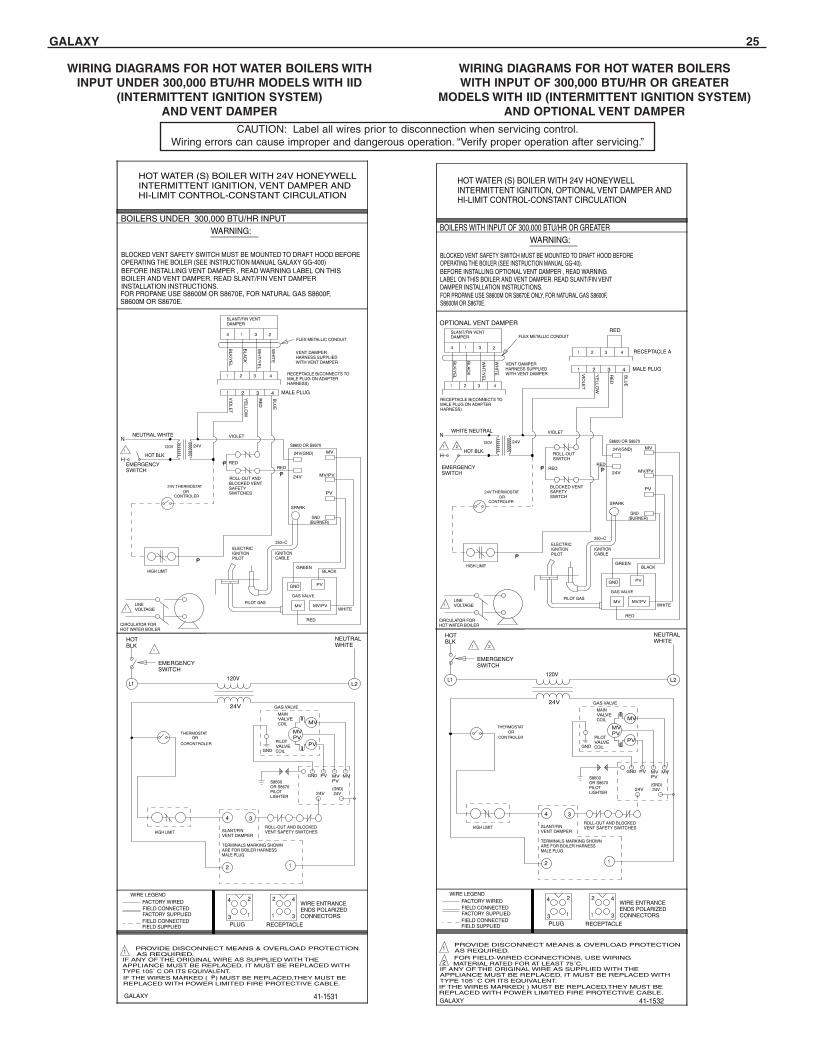
GALAXY 25
WIRING DIAGRAMS FOR HOT WATER BOILERS WITHINPUT UNDER 300,000 BTU/HR MODELS WITH IID
(INTERMITTENT IGNITION SYSTEM)AND VENT DAMPER
WIRING DIAGRAMS FOR HOT WATER BOILERSWITH INPUT OF 300,000 BTU/HR OR GREATER
MODELS WITH IID (INTERMITTENT IGNITION SYSTEM) AND OPTIONAL VENT DAMPER
CAUTION: Label all wires prior to disconnection when servicing control.Wiring errors can cause improper and dangerous operation. “Verify proper operation after servicing.”
HOT WATER (S) BOILER WITH 24V HONEYWELLINTERMITTENT IGNITION, VENT DAMPER ANDHI-LIMIT CONTROL-CONSTANT CIRCULATION
41-1531
BLOCKED VENT SAFETY SWITCH MUST BE MOUNTED TO DRAFT HOOD BEFOREOPERATING THE BOILER (SEE INSTRUCTION MANUAL GALAXY GG-400)
GALAXY
IF THE WIRES MARKED ( ) MUST BE REPLACED,THEY MUST BEREPLACED WITH POWER LIMITED FIRE PROTECTIVE CABLE.
P
NEUTRAL WHITE
MVPV
PV
MV
NEUTRALWHITE
S8600OR S8670PILOTLIGHTER
HIGH LIMIT
RED
BLOCKED VENTSAFETYSWITCHES
S8600 OR S867024V120V
FOR PROPANE USE S8600M OR S8670E, FOR NATURAL GAS S8600F,S8600M OR S8670E.
SLANT/FINVENT DAMPER
TERMINALS MARKING SHOWNARE FOR BOILER HARNESSMALE PLUG.
RED
VIOLET
P
P
P
MAINVALVECOIL
PILOTVALVECOIL
MV
PV
MV/PV
L1 L2
24V(GND)
SPARK
BLACK
4
EMERGENCYSWITCH
H
N
HOT BLK.1
ROLL-OUT AND BLOCKEDVENT SAFETY SWITCHES
ROLL-OUT AND
CIRCULATOR FORHOT WATER BOILER
PILOT GAS
214
BEFORE INSTALLING VENT DAMPER , READ WARNING LABEL ON THISBOILER AND VENT DAMPER. READ SLANT/FIN VENT DAMPERINSTALLATION INSTRUCTIONS.
GND
BLK
/YE
L
BLA
CK
WH
T/Y
EL
WH
ITE
IF ANY OF THE ORIGINAL WIRE AS SUPPLIED WITH THEAPPLIANCE MUST BE REPLACED, IT MUST BE REPLACED WITHTYPE 105˚ C OR ITS EQUIVALENT.
PROVIDE DISCONNECT MEANS & OVERLOAD PROTECTION AS REQUIRED.
BOILERS UNDER 300,000 BTU/HR INPUT
GAS VALVE
1LINEVOLTAGE
(GND) 24V24V
GAS VALVE
MALE PLUG
SLANT/FIN VENTDAMPER
24V
ELECTRICIGNITIONPILOT
WARNING:
PLUG RECEPTACLE
1
WIRE ENTRANCEENDS POLARIZEDCONNECTORS
2
3
2
1 3
4
1
4WIRE LEGEND
FACTORY WIREDFIELD CONNECTEDFACTORY SUPPLIEDFIELD CONNECTEDFIELD SUPPLIED
24V
120V
VIO
LET
YE
LL
OW
BLU
E
RE
D
VENT DAMPERHARNESS SUPPLIEDWITH VENT DAMPER
FLEX METALLIC CONDUIT
RECEPTACLE B(CONNECTS TOMALE PLUG ON ADAPTERHARNESS)
1 2 3 4
3
1 2 3 4
3
12
EMERGENCYSWITCH
MVPV
MVPVGND
IGNITIONCABLE
250∞C
RED
WHITE
GREEN
GND
GND(BURNER)
MV
PV
MV/PV
1
HOTBLK
HIGH LIMIT
THERMOSTATOR
CORONTROLER
24V THERMOSTATOR
CONTROLER
HOT WATER (S) BOILER WITH 24V HONEYWELLINTERMITTENT IGNITION, OPTIONAL VENT DAMPER ANDHI-LIMIT CONTROL-CONSTANT CIRCULATION
HIGH LIMIT
IF THE WIRES MARKED( ) MUST BE REPLACED,THEY MUST BEREPLACED WITH POWER LIMITED FIRE PROTECTIVE CABLE.
BLOCKED VENTSAFETYSWITCH
P REDRED
ROLL-OUTSWITCH
2
2
EMERGENCYSWITCH
MVPV
PV
MV
NEUTRALWHITE
S8600OR S8670PILOTLIGHTER
HIGH LIMIT
S8600 OR S867024V120V
SLANT/FINVENT DAMPER
TERMINALS MARKING SHOWNARE FOR BOILER HARNESSMALE PLUG.
VIOLET
P
P
MAINVALVECOIL
PILOTVALVECOIL
MV
PV
MV/PV
L1 L2
24V(GND)
SPARK
BLACK
4
H
NWHITE NEUTRAL
HOT BLK.1
ROLL-OUT AND BLOCKEDVENT SAFETY SWITCHES
CIRCULATOR FORHOT WATER BOILER
PILOT GAS
GND
GAS VALVE
1LINEVOLTAGE
(GND) 24V24V
GAS VALVE
MALE PLUG
24V
ELECTRICIGNITIONPILOT
24V
120V
YE
LLO
W
BLU
E
RE
D
1 2 3 4
3
12
EMERGENCYSWITCH
MVPV
MVPVGND
IGNITIONCABLE
250∞C
RED
WHITE
GREEN
GND
GND(BURNER)
MV
PV
MV/PV
1
HOTBLK
VIO
LET
RECEPTACLE B(CONNECTS TOMALE PLUG ON ADAPTERHARNESS)
OPTIONAL VENT DAMPER
41-1532
FLEX METALLIC CONDUIT
FOR FIELD-WIRED CONNECTIONS, USE WIRING MATERIAL RATED FOR AT LEAST 75˚C.2
1PROVIDE DISCONNECT MEANS & OVERLOAD PROTECTION
AS REQUIRED.
FOR PROPANE USE S8600M OR S8670E ONLY, FOR NATURAL GAS S8600F,S8600M OR S8670E.
BLOCKED VENT SAFETY SWITCH MUST BE MOUNTED TO DRAFT HOOD BEFOREOPERATING THE BOILER (SEE INSTRUCTION MANUAL GG-40).
214
GALAXY
VENT DAMPERHARNESS SUPPLIEDWITH VENT DAMPER
RECEPTACLE AB
LK/Y
EL
WH
T/Y
EL
BLA
CK
WH
ITE
BOILERS WITH INPUT OF 300,000 BTU/HR OR GREATER
BEFORE INSTALLING OPTIONAL VENT DAMPER , READ WARNINGLABEL ON THIS BOILER AND VENT DAMPER. READ SLANT/FIN VENTDAMPER INSTALLATION INSTRUCTIONS.
RED
4321
3
SLANT/FIN VENTDAMPER
IF ANY OF THE ORIGINAL WIRE AS SUPPLIED WITH THEAPPLIANCE MUST BE REPLACED, IT MUST BE REPLACED WITHTYPE 105˚ C OR ITS EQUIVALENT.
WARNING:
PLUG RECEPTACLE
WIRE ENTRANCEENDS POLARIZEDCONNECTORS
2
3
2
1 3
4
1
4WIRE LEGEND
FACTORY WIREDFIELD CONNECTEDFACTORY SUPPLIEDFIELD CONNECTEDFIELD SUPPLIED
1 2 3 4
THERMOSTATOR
CONTROLER
24V THERMOSTATOR
CONTROLER

26 GALAXY
PUMP OR VALVE ZONING OF WATER BOILERSCOMBINATION CONTROLS WITH T TV Z TERMINALS*

GALAXY 27
BURNERS FAIL TO OPERATECAUSE1. Safety pilot out, or flame too low.2. Gas supply valve shut off.3. Electric switch open.4. Blown or defective line fuse.5. Operating or limit control contacts open or dirty.6. Defective gas valve or pressure regulator; or plugged bleed
line.7. Defective low voltage transformer.8. Obstruction at main burner orifice.9. Break in wiring or loose contact at control terminals.
10. Improper wiring.11. Improper controls.12. Rollout or blocked vent safety switch open.
BURNERS WILL NOT SHUT OFFCAUSE1. Defective operating control, gas valve, or high limit control.2. Improper wiring or short circuit.
FLASH BACK - BURNING AT ORIFICESCAUSE1. Manifold gas pressure too low.2. Improper primary air adjustment.3. Gas regulator bleed too slow.4. Burrs on orifice.5. Improperly drilled orifice plugs.6. Leaking automatic gas valve.7. Adverse draft condition in boiler room.8. Low main gas pressure.9. Safety pilot improperly installed.
DELAYED IGNITIONCAUSE1. Pilot flame too low.2. Pilot burner ports or pilot orifice clogged.3. Burners or orifices out of alignment.4. Excessive primary air.5. Excessive burner input.6. Adverse draft condition in boiler room.
FUMES AND GAS ODORSCAUSE1. Leaks in gas piping or accessories.2. Gas leaks in service line or meter connections.3. Blocked chimney.4. Boiler flueways blocked with soot.5. Undersized breeching or too many turns in breeching.6. Adverse draft condition in boiler room.7. Overfiring.
CONDENSATION IN BOILER FLUES OR IN VENT SYSTEMCAUSE1. Underfiring.2. Boiler water maintained at too low a temperature level.3. Long horizontal run of smokepipe.4. Inadequate chimney or venting system.
REMEDY1. Check, clean, re-light. See instructions.2. Open gas valve(s).3. Close switch.4. Replace fuse.5. Check control. Clean contacts or replace control.6. Repair or replace.7. Replace aquastat.8. Check, clean and reinstall.9. Check with test-light and correct.
10. Check and correct in accordance with wiring diagramsincluded with appliance instructions.
11. Install proper controls.12. Replace rollout switch (inspect flue passages prior to
replacement) or reset blocked vent safety switch bydepressing the reset button
REMEDY1. Check, repair or replace.2. Check wiring and controls.
REMEDY1. Adjust to proper manifold pressure.2. Adjust air to produce soft, clean flame.3. Adjust bleed opening.4. Remove burrs.5. Install orifice plugs with proper drilling.6. Repair or replace.7. Check air supply and venting system.8. Contact utility.9. Correct to manufacturer's recommendations.
REMEDY1. Increase gas supply to pilot.2. Clean ports or orifices.3. Realign burners or manifold.4. Adjust primary air shutters.5. Check and reduce to input shown on rating plate.6. Check air supply and venting system.
REMEDY1. Locate leaks and repair.2. Close service supply valve - shut down appliance and
notify utility.3. Check and repair chimney.4. Clean flueways and adjust burners as described in the
installation instructions.5. Check manufacturer's recommendations.6. Check air supply and venting system.7. Adjust gas input to that shown on boiler rating plate.
REMEDY1. Increase firing rate to that shown on rating plate.2. Set low limit controls to maintain a higher water tempera-
ture. If boiler is not equipped with low limit replace withone which has a combination low limit/high limit aquastat.
3. Relocate boiler or insulate breeching.4. Check chimney and venting recommendations.
GENERAL TROUBLESHOOTING GUIDE FOR SERVICEPEOPLE

28 GALAXY
PIPING A HEATING — COOLING SYSTEMTO A WATER BOILER AND CHILLER
Figure below illustrates a method of piping a heating-coolingsystem to a water boiler and a chiller. Hand valves (shown) orautomatic valves must be installed to prevent circulation ofchilled water in the boiler or hot water in the chiller.
IF REPLACEMENT PARTS ARE NEEDED
When parts are needed, refer to boiler model and serial number shownon the boiler name/rating plate. Refer to the following parts lists for partnumbers; publication number GG-10PL for Galaxy GG Series GX-10PLfor Galaxy GX and GXHA-10PL for GXHA Series boilers. Wheneverpossible refer to the original order by number and date.
Control identification and replacement should not be attempted byunskilled personnel. Only simple, easily identified controls and partsmay be obtained locally. All other controls and parts should be identifiedby and ordered from Slant/Fin. Relief/Safety valves must be ASMErated for the pressure and gross output of the boiler.
The air-control system and pressure control system must oper-ate with chiller only, or the boiler only, being valved to the pipingsystem. Separate control devices on the boiler and chiller maybe used, or a single set of air and pressure controls on thecommon piping may be preferred.
If the boiler is used to supply hot water to heating coils in airhandling units, flow control valves or other devices must beinstalled to prevent gravity circulation of water in the coils dur-ing the cooling cycle.
When ordering replacement parts, specify the boiler model number, serial number and gasby name (natural or propane). For replacement parts, heating contractors should contact theirSlant/Fin boiler distributor.

GALAXY 29
APPENDIX A
Removal of Existing Boiler from Common Vent System
"At the time of removal of an existing boiler, the following steps shall be followed with each appliance remaining connected to the com-mon venting system placed in operation, while the other appliances remaining connected to the common venting system are not inoperation."
(a) Seal any unused openings in the common venting system.
(b) Visually inspect the venting system for proper size and hori-zontal pitch and determine there is no blockage or restric-tion, leakage, corrosion and other deficiencies which couldcause an unsafe condition.
(c) Insofar as is practical, close all building doors and windowsand all doors between the space in which the appliancesremaining connected to the common venting system arelocated and other spaces of the building. Turn on clothesdryers and any appliance not connected to the commonventing system. Turn on any exhaust fans, such as rangehoods and bathroom exhausts, so they will operate at maxi-mum speed. DO NOT operate a summer exhaust fan.Close fireplace dampers.
(d) Place in operation the appliance being inspected. Followthe lighting instructions. Adjust thermostat so appliance willoperate continuously.
(e) Test for spillage at the draft hood relief opening after 5 min-
utes of main burner operation. Use the flame of a match orcandle, or smoke from a cigarette, cigar or pipe.
(f) After it has been determined that each appliance remainingconnected to the common venting system properly ventswhen tested as outlined above, return doors, windows,exhaust fans, fireplace dampers and any other gas-burningappliance to their previous conditions of use.
(g) Any improper operation of the common venting systemshould be corrected so the installation conforms with theNational Fuel Gas Code, ANSI Z223.1-latest edition. Whenresizing any portion of the common venting system, thecommon venting system should be resized to approach theminimum size as determined using the appropriate tables inAppendix G in the National Fuel Gas Code, ANSI Z223.1-latest edition.

SLANT/FIN CORPORATION, Greenvale, N.Y. 11548 • Phone: (516) 484-2600FAX: (516) 484-5921 • Canada: Slant/Fin LTD/LTEE, Mississauga, Ontario
www.slantfin.com
©Slant/Fin Corp. 2006