gas electron multiplier (gem) technology gaseous detector
TRANSCRIPT
F. Murtas LNF/INFN Frascati 28 November 2002
SRG LabDevelopment of a
gaseous detector based on Gas Electron Multiplier (GEM) Technology
Introduction
Gas mixture choice
Performance: gain, time resolution, efficiency
Aging and discharges
Chamber 20x24 cm2
Other possible applications
Conclusions
F.Murtas (LNF-INFN)
F. Murtas LNF/INFN Frascati 28 November 2002
SRG LabGas Electron Multiplier
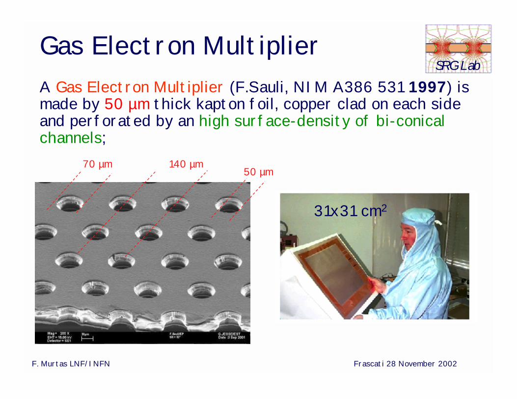
70 µm 140 µm
A Gas Electron Multiplier (F.Sauli, NIM A386 531 1997) is made by 50 µm thick kapton foil, copper clad on each side and perforated by an high surface-density of bi-conical channels;
50 µm
31x31 cm2
F. Murtas LNF/INFN Frascati 28 November 2002
SRG LabGEM foil construction (CERN)
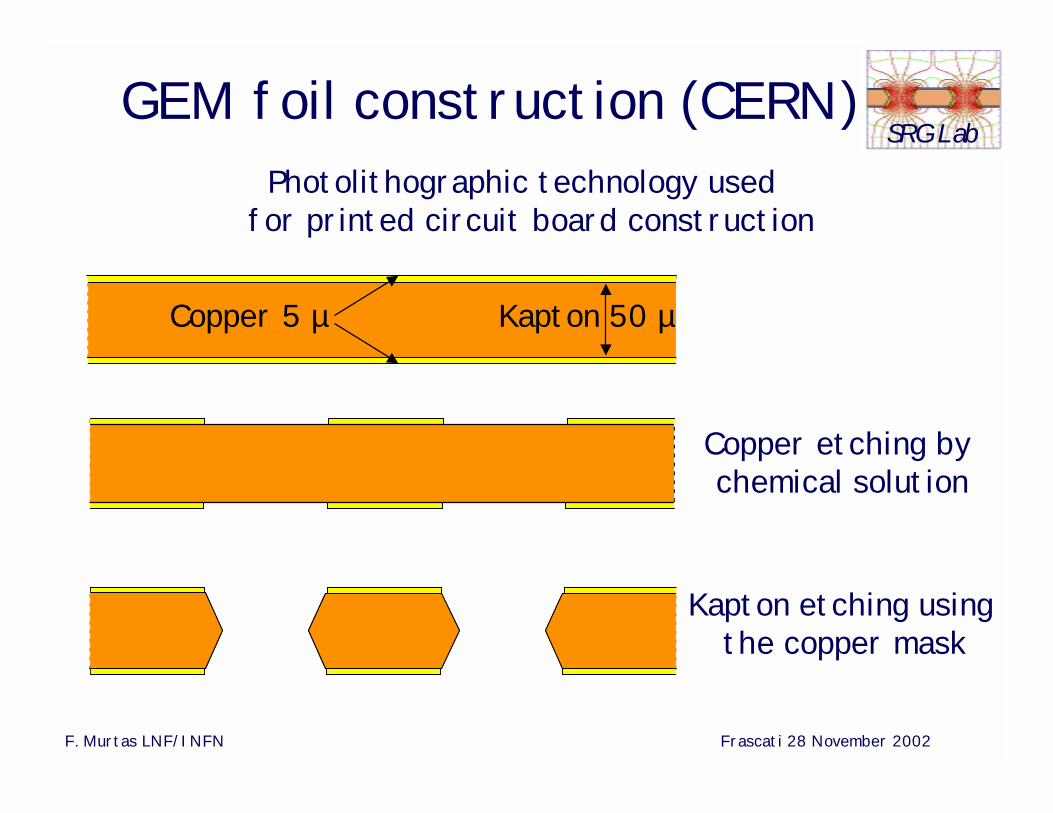
Kapton 50 µCopper 5 µ
Copper etching bychemical solution
Kapton etching using the copper mask
Photolithographic technology used for printed circuit board construction
F. Murtas LNF/INFN Frascati 28 November 2002
SRG LabGEM different geometries
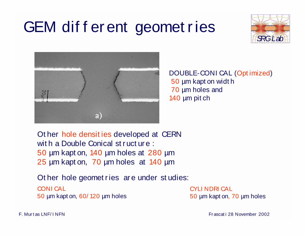
Other hole densities developed at CERN with a Double Conical structure :50 µm kapton, 140 µm holes at 280 µm25 µm kapton, 70 µm holes at 140 µm
DOUBLE-CONICAL (Optimized)50 µm kapton width 70 µm holes and
140 µm pitch
Other hole geometries are under studies: CONICAL50 µm kapton, 60/120 µm holes
CYLINDRICAL50 µm kapton, 70 µm holes
F. Murtas LNF/INFN Frascati 28 November 2002
SRG LabGas Electron Multiplier
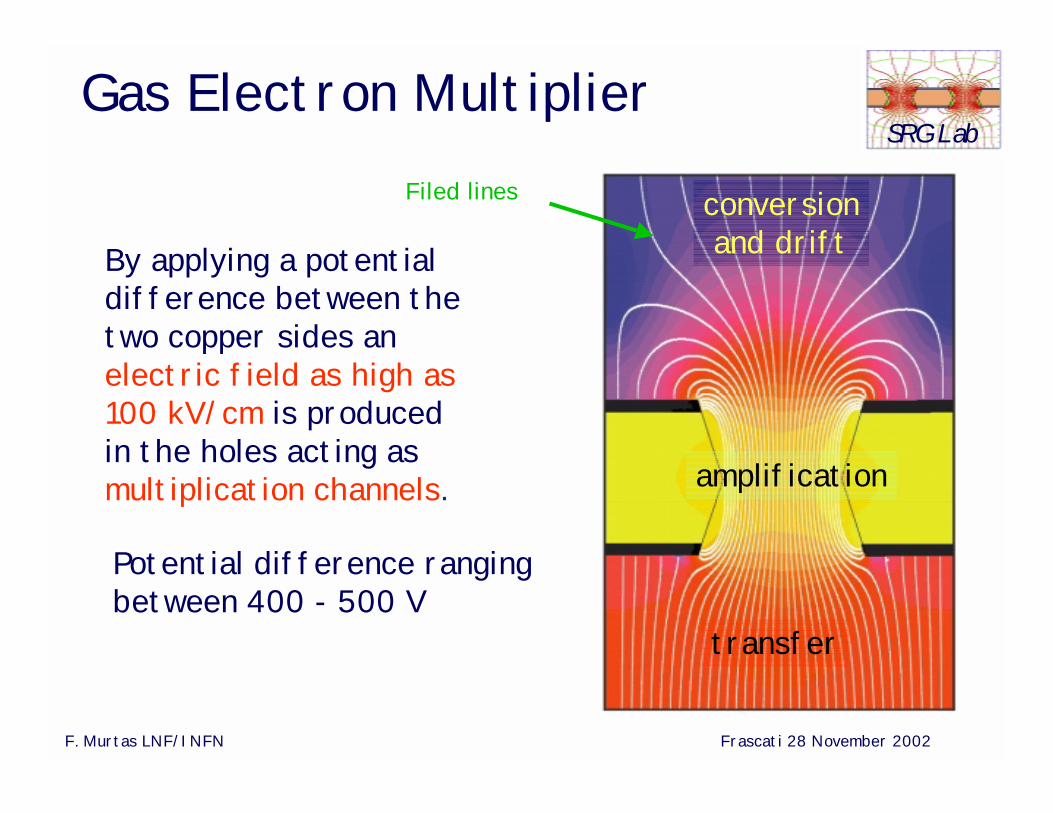
By applying a potential difference between the two copper sides anelectric field as high as 100 kV/cm is produced in the holes acting asmultiplication channels.
Filed lines
transfer
amplification
conversionand drift
Potential difference ranging between 400 - 500 V

F. Murtas LNF/INFN Frascati 28 November 2002
SRG LabGEM principia: electrons
Time = 0 ns
electron clusterion cluster
Time = ~1 nsTime = ~3 ns
one cluster could be collected by copper
the first cluster begin the multiplication
Time = ~6 ns
F. Murtas LNF/INFN Frascati 28 November 2002
SRG Lab
now only ions remaininside the holes
GEM Principle: ions
Time = ~10 ns
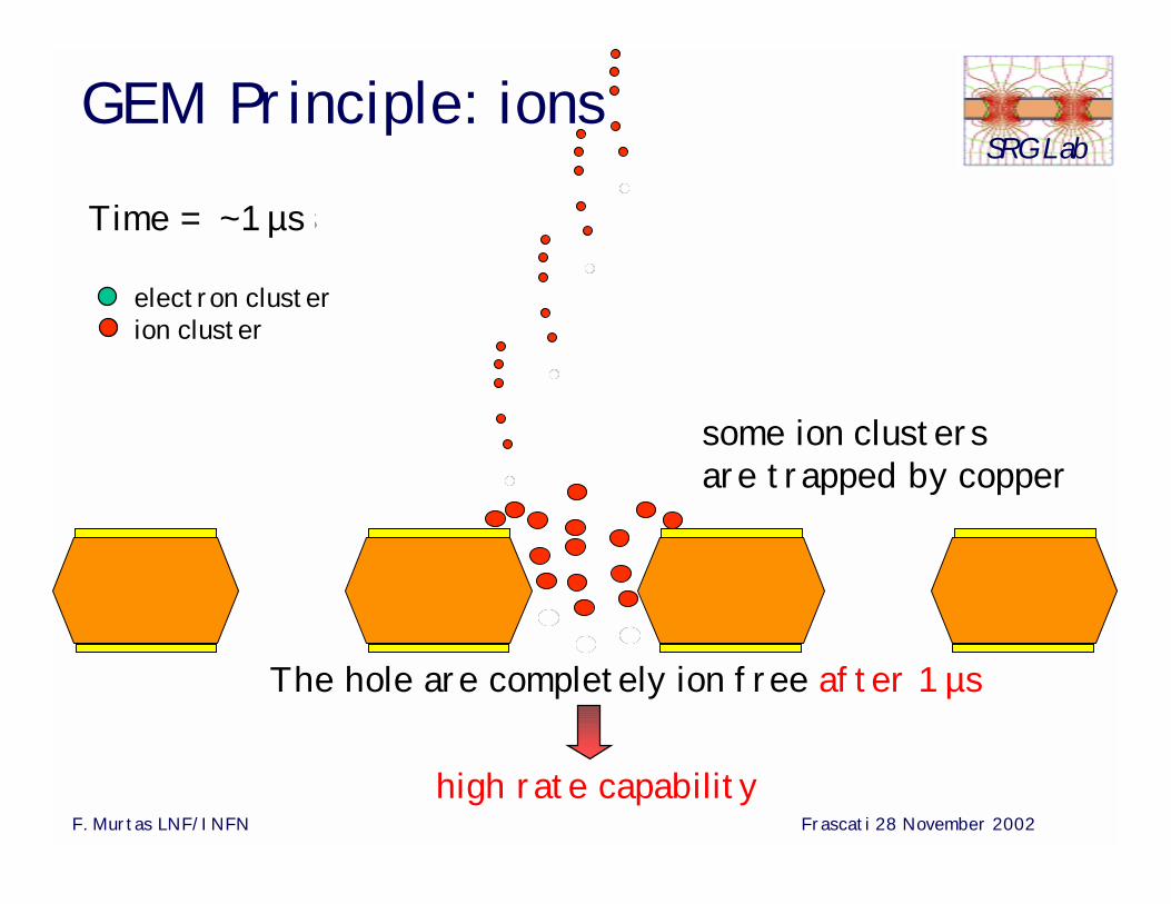
electron clusterion cluster
Time = ~1 µs
the ions drift versusgem upperside some ion clusters are trapped by copper
high rate capability
The hole are completely ion free after 1 µs
F. Murtas LNF/INFN Frascati 28 November 2002
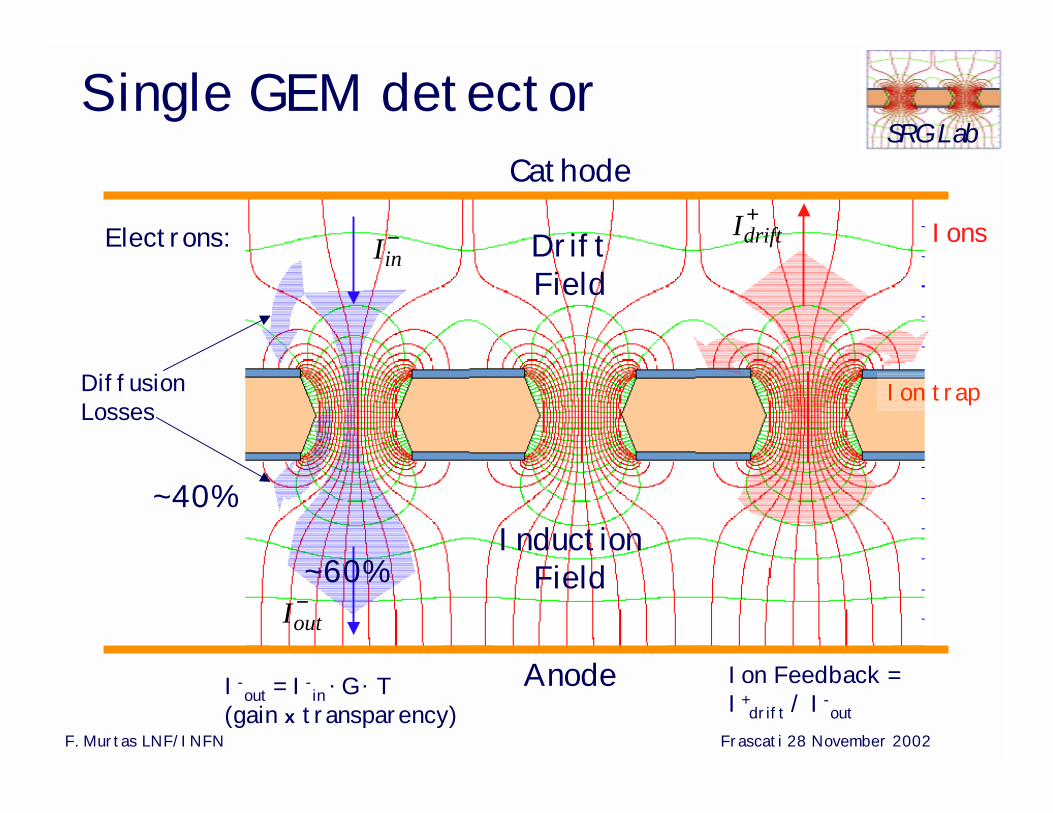
SRG LabSingle GEM detector
Iin−
Iout−
Electrons:
Diffusion Losses
I-out = I-
in . G . T
(gain x transparency)Ion Feedback =I+
drift / I-out
IonsIdrift+
Ion trap
Cathode
Anode
DriftField
InductionField
~40%
~60%
F. Murtas LNF/INFN Frascati 28 November 2002
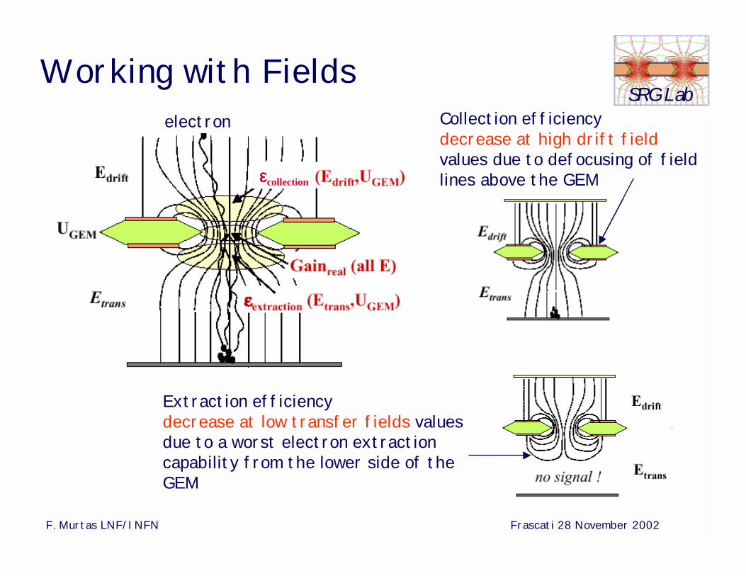
SRG LabWorking with Fields
electron
εεεεcollection
Extraction efficiency decrease at low transfer fields values due to a worst electron extraction capability from the lower side of the GEM
Collection efficiency decrease at high drift fieldvalues due to defocusing of field lines above the GEM
F. Murtas LNF/INFN Frascati 28 November 2002
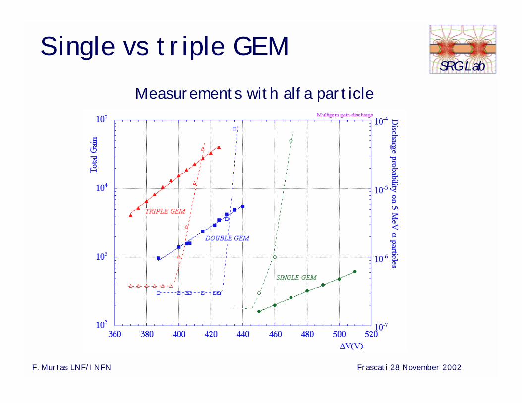
SRG LabSingle vs triple GEM
Measurements with alfa particle
With a single GEM
is possible reach gains ~103
but with “high” discharge probability
F. Murtas LNF/INFN Frascati 28 November 2002
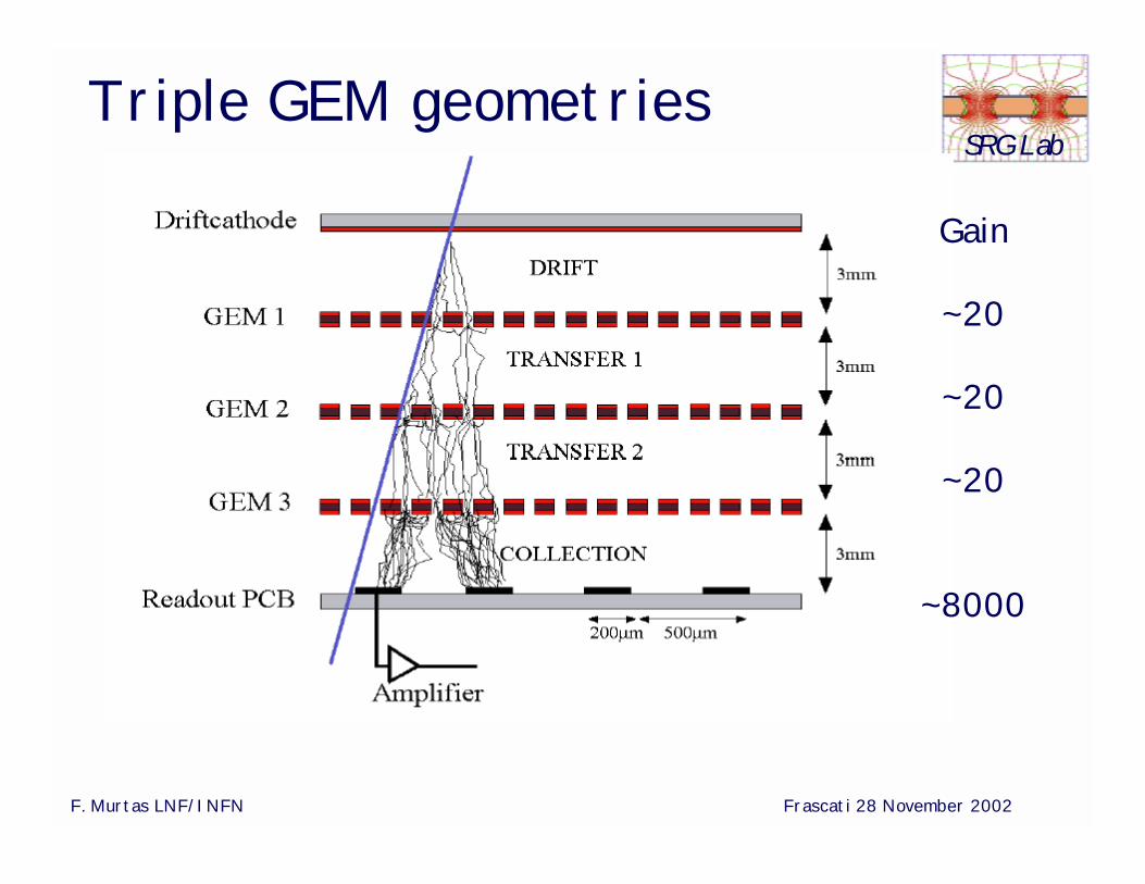
SRG LabTriple GEM geometries
Gain
~20
~20
~20
~8000
F. Murtas LNF/INFN Frascati 28 November 2002
SRG Lab
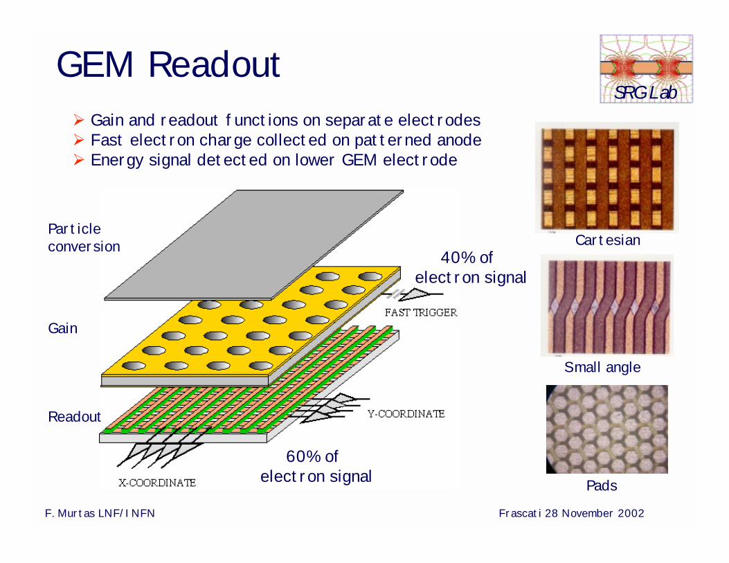
Cartesian
Small angle
Pads
Gain and readout functions on separate electrodes Fast electron charge collected on patterned anode Energy signal detected on lower GEM electrode
GEM Readout
40% of electron signal
60% of electron signal
Particle conversion
Gain
Readout
F. Murtas LNF/INFN Frascati 28 November 2002
SRG LabGEM Group
Laboratori Nazionali di Frascati - INFN, Frascati , Italy
G. Bencivenni, P. de Simone, F.Murtas,
M. Poli-Lener, M.Alfonsi
Sezione INFN di Cagliari – Cagliari, Italy
W. Bonivento, A.Cardini,
C. Deplano, D.Pinci, D. Raspino
With the technical support of :SSCR /SPAS (LNF)
Electronic Pool Service (LNF)Electronic Pool Service (CA)
F. Murtas LNF/INFN Frascati 28 November 2002
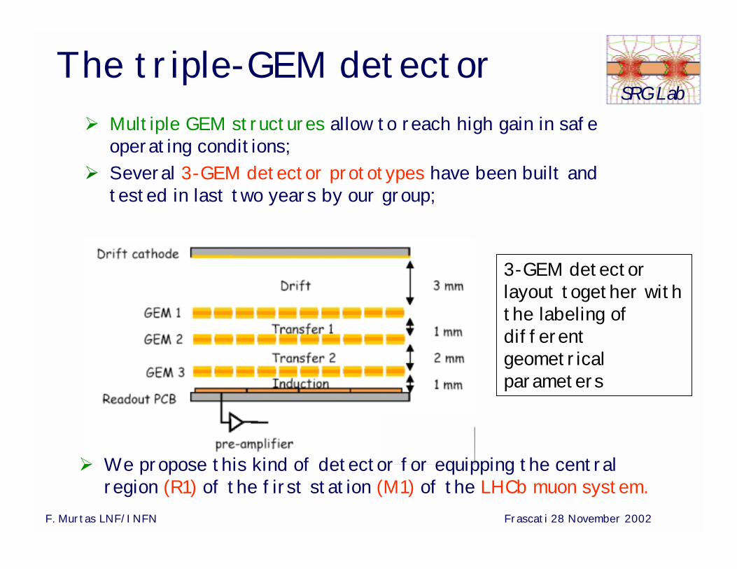
SRG LabThe triple-GEM detector
Multiple GEM structures allow to reach high gain in safe operating conditions;
Several 3-GEM detector prototypes have been built and tested in last two years by our group;
3-GEM detector layout together with the labeling of different geometrical parameters
We propose this kind of detector for equipping the central region (R1) of the first station (M1) of the LHCb muon system.
F. Murtas LNF/INFN Frascati 28 November 2002
SRG Lab
A triple-GEM detector is being proposed for the Central Region of the first Muon Station of the LHCb experiment at CERN, for which the requirements are:
Rate Capability ~ up to 0.5 MHz/cm2
Station Efficiency ~ 99% in a 25 ns time window (*) Cluster Size ~ 1.2 for a 10x25 mm2 pad size Radiation Hardness ~ 6 C/cm2 in 10 years (for G ~ 104)
(*) A station is made of two detectors “in OR”, pad by pad.This improves time resolution and provides some redundancy.
Detector RequirementsDetector Requirements
F. Murtas LNF/INFN Frascati 28 November 2002
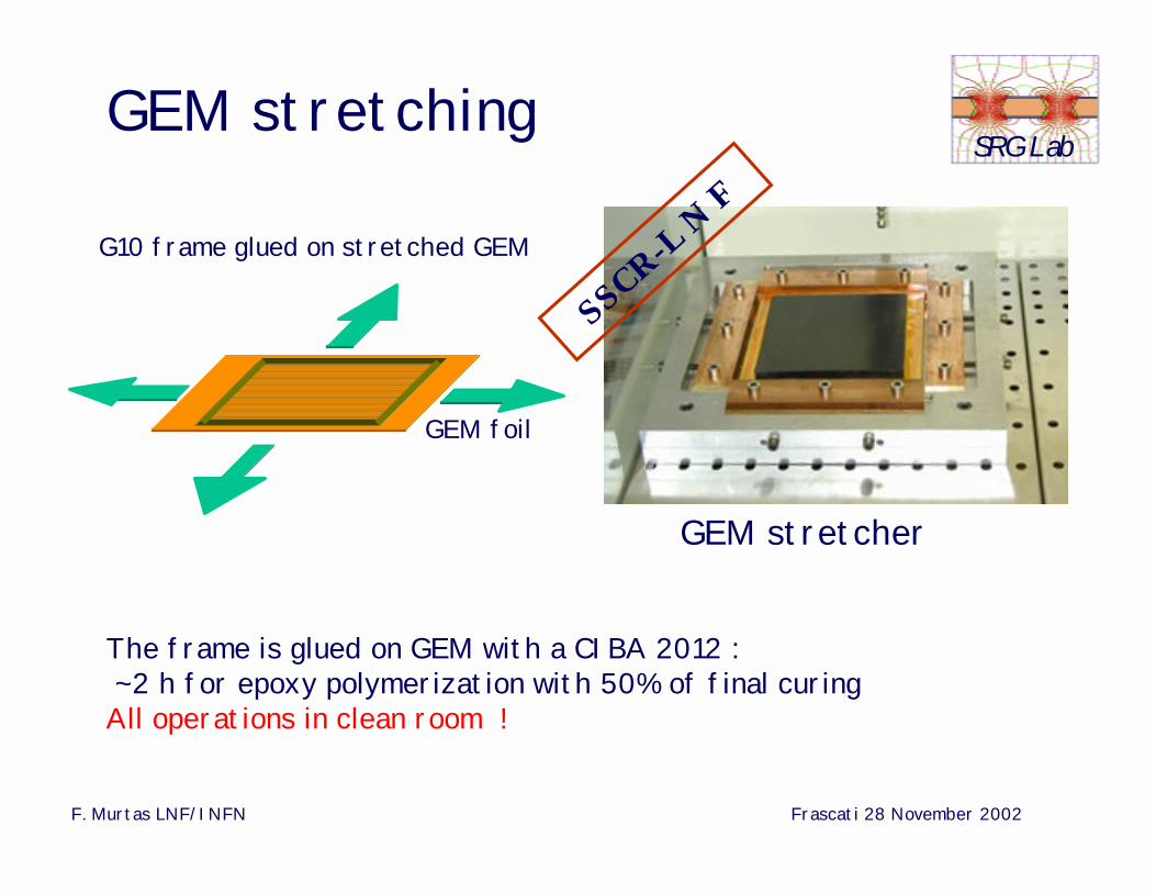
SRG LabGEM stretching
GEM stretcher
The frame is glued on GEM with a CIBA 2012 :~2 h for epoxy polymerization with 50% of final curing
All operations in clean room !
G10 frame glued on stretched GEM
GEM foil
SSCR-L N
F
F. Murtas LNF/INFN Frascati 28 November 2002
SRG Lab
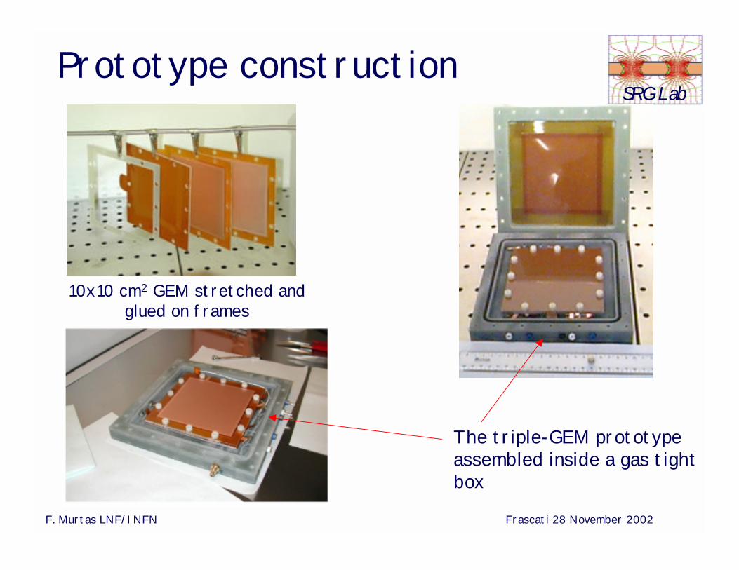
10x10 cm2 GEM stretched and glued on frames
The triple-GEM prototypeassembled inside a gas tightbox
Prototype construction

F. Murtas LNF/INFN Frascati 28 November 2002
SRG LabX-Ray System @ LNF
E = 5.9 keV monochromatic X-ray beam Flux = 50 MHz/cm2 (102 times max LHCb rate) Spot size = π mm2
With this setup we have measured vs Gas mixture :Gain , Plateau , Rate Capability and Aging
F. Murtas LNF/INFN Frascati 28 November 2002
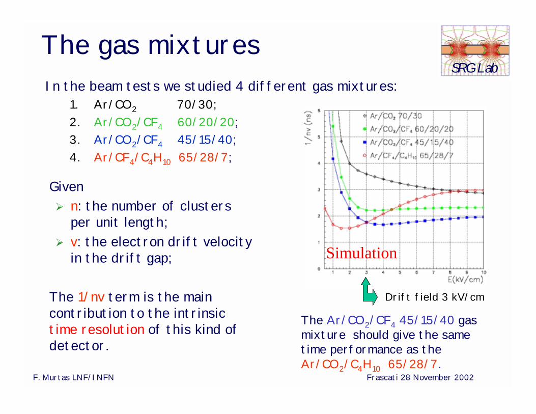
SRG LabThe gas mixturesIn the beam tests we studied 4 different gas mixtures:
1. Ar/CO2 70/30;2. Ar/CO2/CF4 60/20/20;3. Ar/CO2/CF4 45/15/40;4. Ar/CF4/C4H10 65/28/7;
Drift field 3 kV/cm
Given n: the number of clusters
per unit length; v: the electron drift velocity
in the drift gap;
The 1/nv term is the main contribution to the intrinsictime resolution of this kind of detector.
The Ar/CO2/CF4 45/15/40 gas mixture should give the same time performance as theAr/CO2/C4H10 65/28/7.
Simulation
F. Murtas LNF/INFN Frascati 28 November 2002
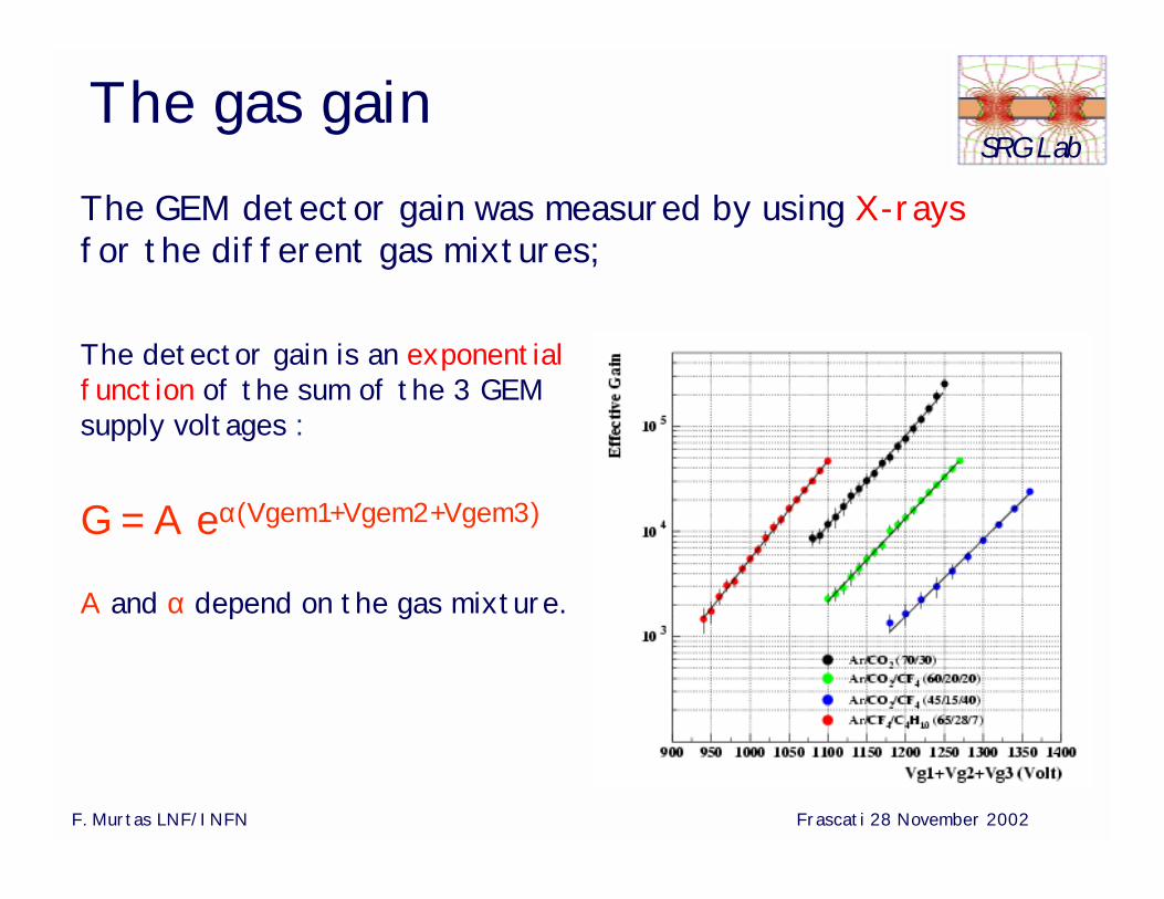
SRG LabThe gas gainThe GEM detector gain was measured by using X-raysfor the different gas mixtures;
The detector gain is an exponential function of the sum of the 3 GEM supply voltages :
G = A eα(Vgem1+Vgem2+Vgem3)
A and α depend on the gas mixture.
F. Murtas LNF/INFN Frascati 28 November 2002
SRG Lab
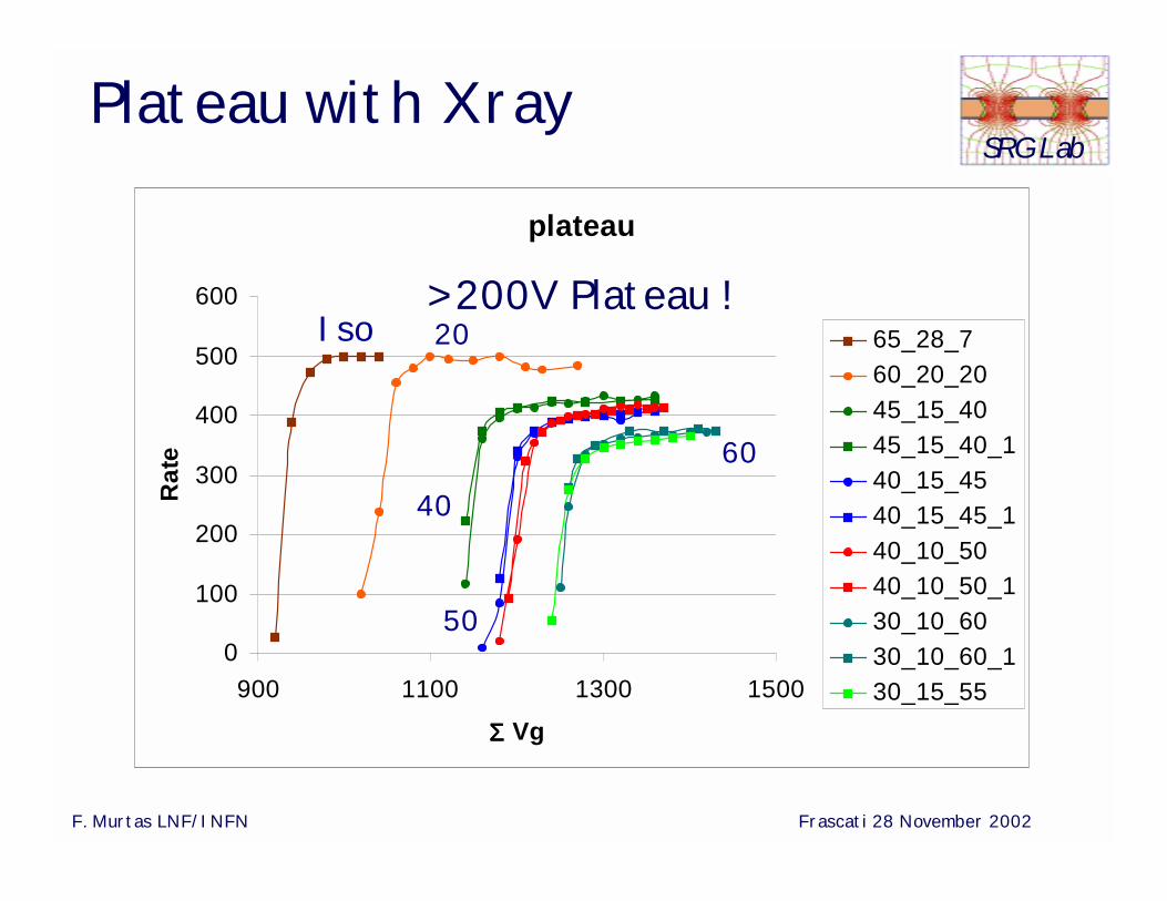
plateau
0
100
200
300
400
500
600
900 1100 1300 1500
ΣΣΣΣ Vg
Rat
e
65_28_760_20_2045_15_4045_15_40_140_15_4540_15_45_140_10_5040_10_50_130_10_6030_10_60_130_15_55
Iso 20
40
60
50
Plateau with Xray
> 200V Plateau !
F. Murtas LNF/INFN Frascati 28 November 2002
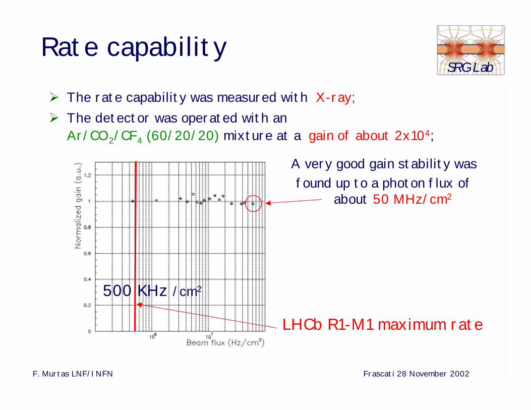
SRG LabRate capability The rate capability was measured with X-ray; The detector was operated with an
Ar/CO2/CF4 (60/20/20) mixture at a gain of about 2x10⁴;
LHCb R1-M1 maximum rate
500 KHz /cm2
A very good gain stability wasfound up to a photon flux of
about 50 MHz/cm2
F. Murtas LNF/INFN Frascati 28 November 2002
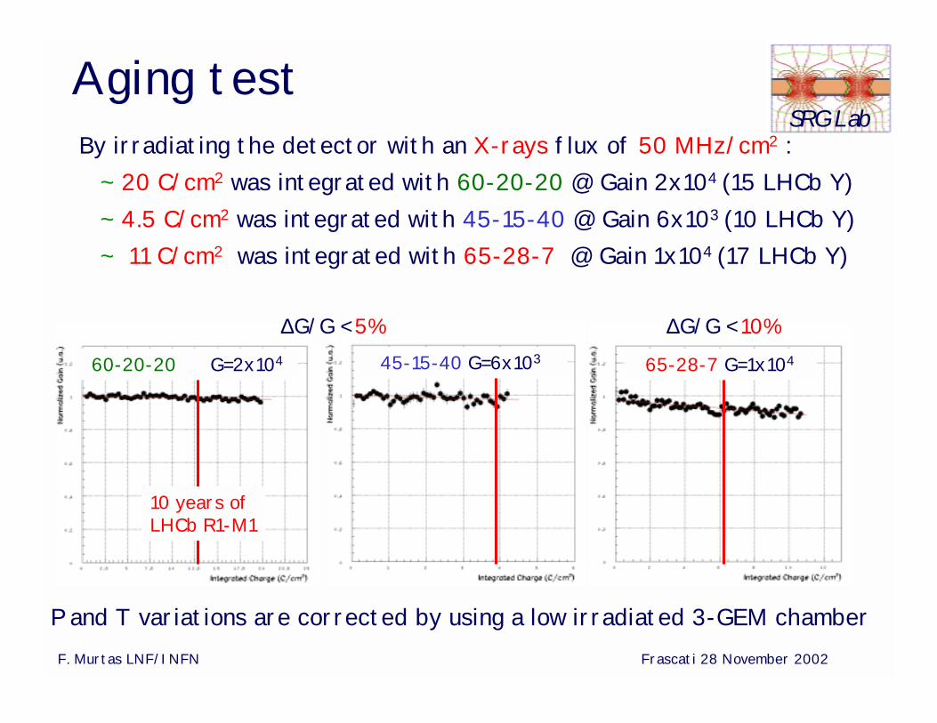
SRG LabAging testBy irradiating the detector with an X-rays flux of 50 MHz/cm2 :
~ 20 C/cm2 was integrated with 60-20-20 @ Gain 2x10⁴ (15 LHCb Y)~ 4.5 C/cm2 was integrated with 45-15-40 @ Gain 6x10³ (10 LHCb Y)~ 11 C/cm2 was integrated with 65-28-7 @ Gain 1x10⁴ (17 LHCb Y)
P and T variations are corrected by using a low irradiated 3-GEM chamber
65-28-7 G=1x10⁴
10 years of LHCb R1-M1
45-15-40 G=6x10360-20-20 G=2x10⁴
∆G/G < 5% ∆G/G < 10%
F. Murtas LNF/INFN Frascati 28 November 2002
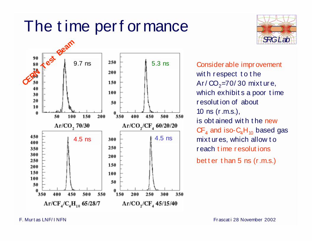
SRG LabThe time performance
Considerable improvementwith respect to the Ar/CO2=70/30 mixture, which exhibits a poor time resolution of about 10 ns (r.m.s.), is obtained with the new CF4 and iso-C4H10 based gas mixtures, which allow to reach time resolutions better than 5 ns (r.m.s.)
9.7 ns 5.3 ns
4.5 ns 4.5 ns
CERN
Test
Beam
F. Murtas LNF/INFN Frascati 28 November 2002
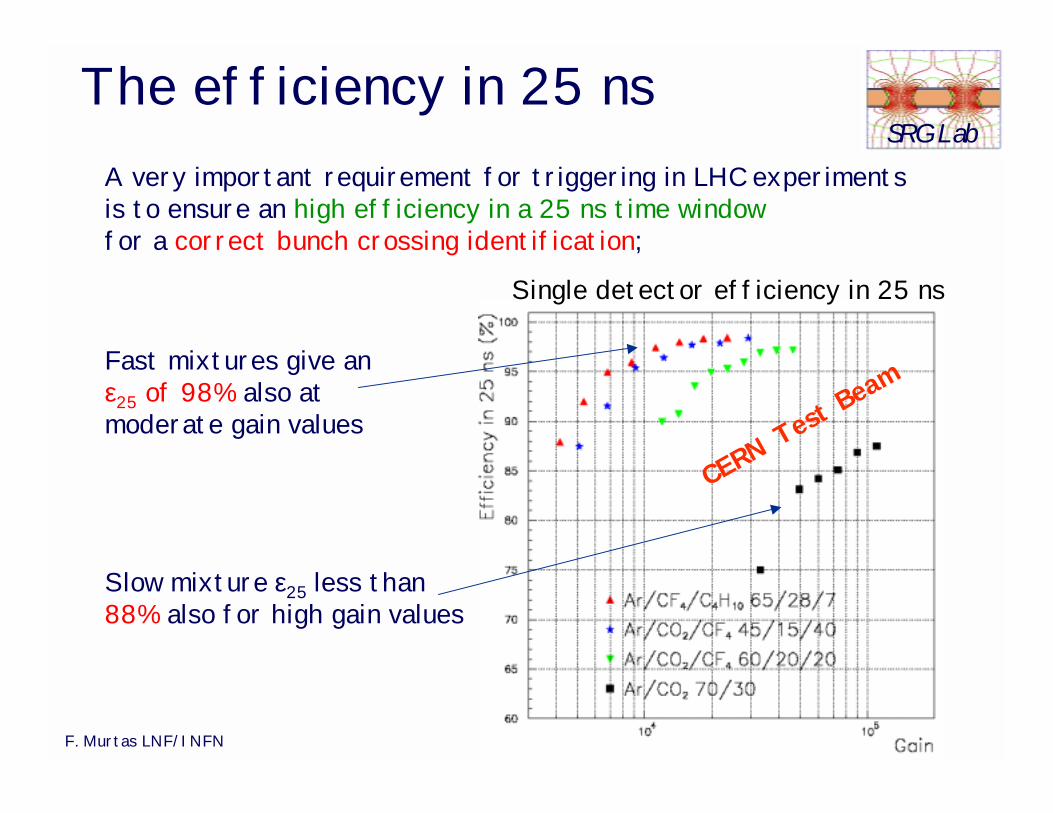
SRG LabThe efficiency in 25 ns
A very important requirement for triggering in LHC experiments is to ensure an high efficiency in a 25 ns time window for a correct bunch crossing identification;
Slow mixture ε25 less than 88% also for high gain values
Fast mixtures give anε25 of 98% also at moderate gain values
Single detector efficiency in 25 ns
CERN Te
st Beam
F. Murtas LNF/INFN Frascati 28 November 2002
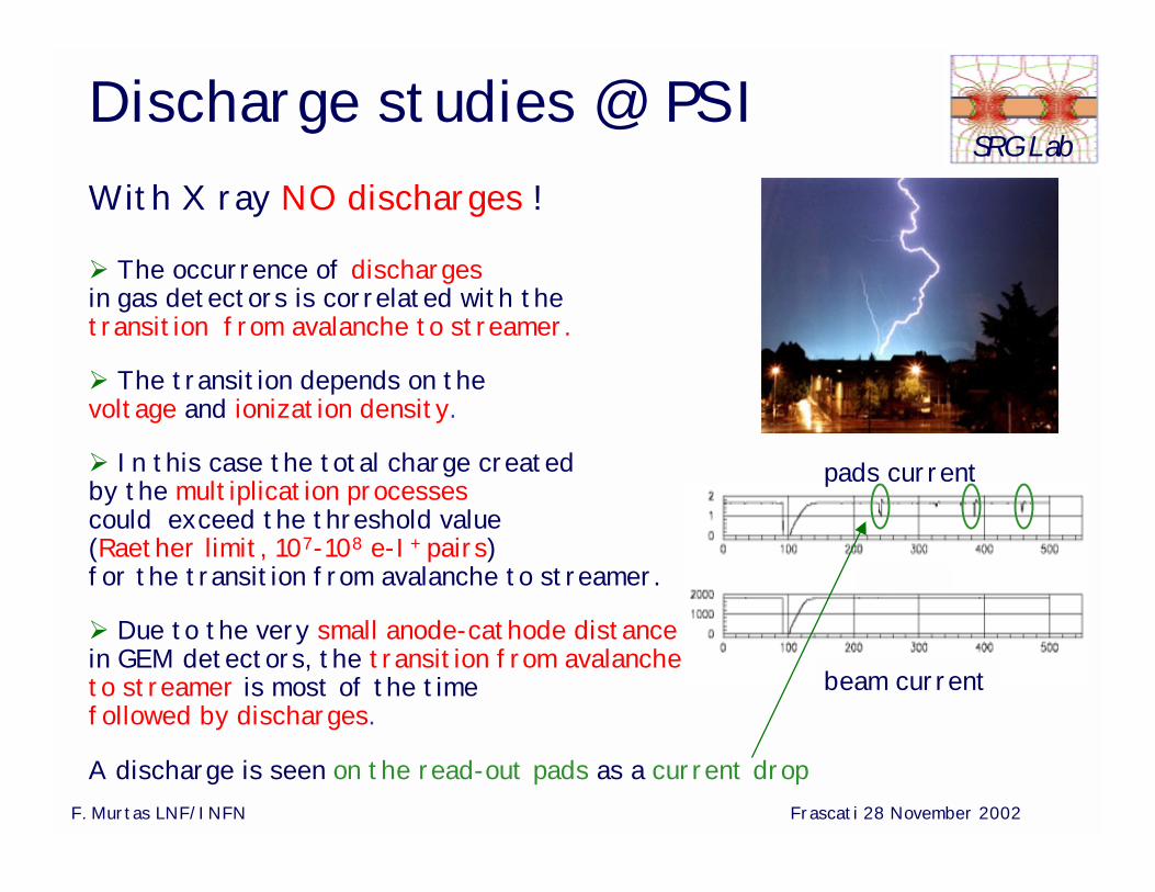
SRG LabDischarge studies @ PSI
The occurrence of dischargesin gas detectors is correlated with thetransition from avalanche to streamer.
The transition depends on the voltage and ionization density.
In this case the total charge created by the multiplication processescould exceed the threshold value(Raether limit, 107-108 e-I+ pairs) for the transition from avalanche to streamer.
Due to the very small anode-cathode distancein GEM detectors, the transition from avalanche to streamer is most of the time followed by discharges.
pads current
beam current
A discharge is seen on the read-out pads as a current drop
With X ray NO discharges !
F. Murtas LNF/INFN Frascati 28 November 2002
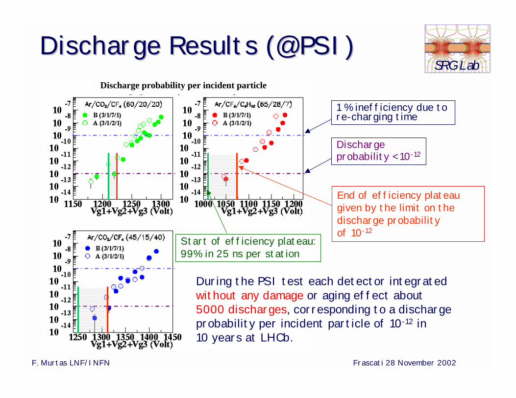
SRG LabDDischargeischarge Results (@PSI)Results (@PSI)
Discharge probability < 10-12
1 % inefficiency due to re-charging time
End of efficiency plateau given by the limit on the discharge probability of 10-12
During the PSI test each detector integratedwithout any damage or aging effect about 5000 discharges, corresponding to a dischargeprobability per incident particle of 10-12 in 10 years at LHCb.
Discharge probability per incident particle
Start of efficiency plateau:99% in 25 ns per station
F. Murtas LNF/INFN Frascati 28 November 2002
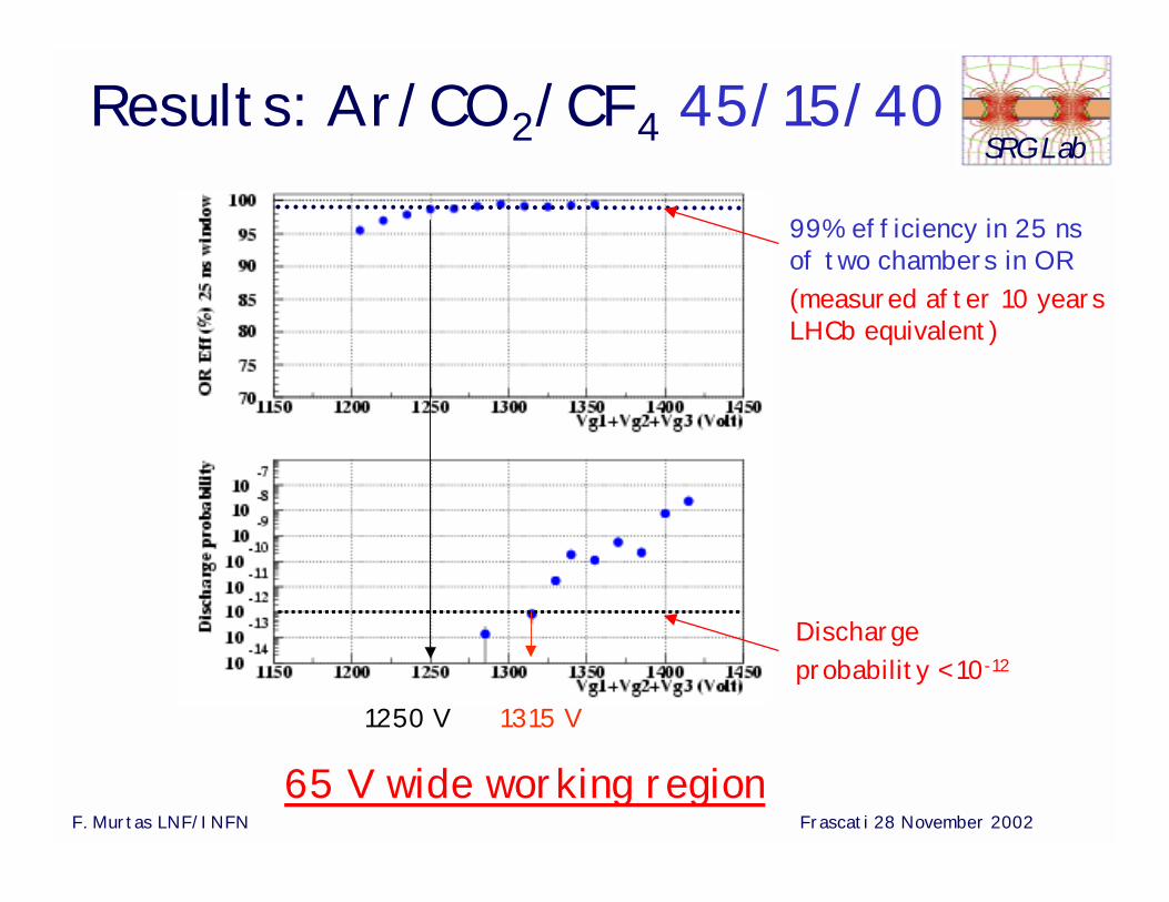
SRG LabResults: Ar/CO2/CF4 45/15/40
Discharge probability < 10-12
1250 V 1315 V
65 V wide working region
99% efficiency in 25 ns of two chambers in OR(measured after 10 yearsLHCb equivalent)
F. Murtas LNF/INFN Frascati 28 November 2002
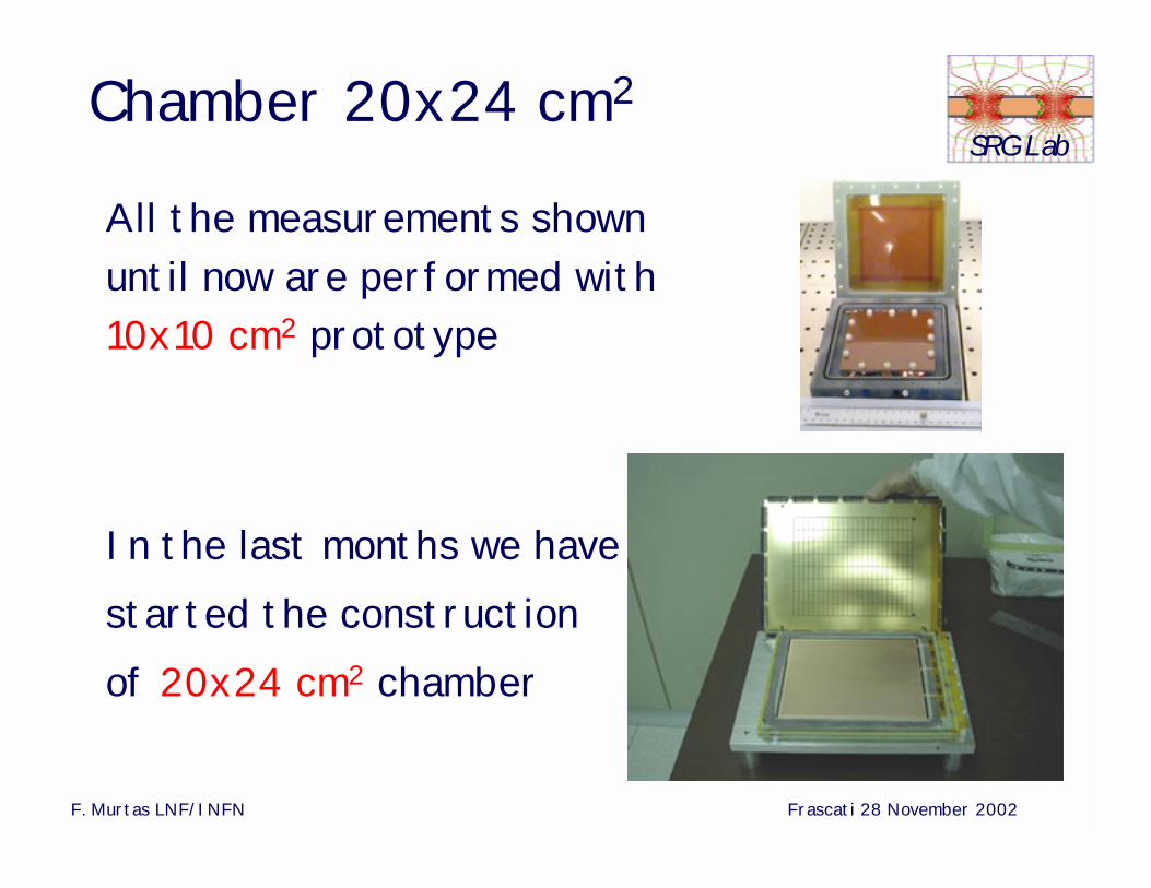
SRG LabChamber 20x24 cm2
All the measurements shown until now are performed with 10x10 cm2 prototype
In the last months we have started the construction of 20x24 cm2 chamber
F. Murtas LNF/INFN Frascati 28 November 2002
SRG Lab
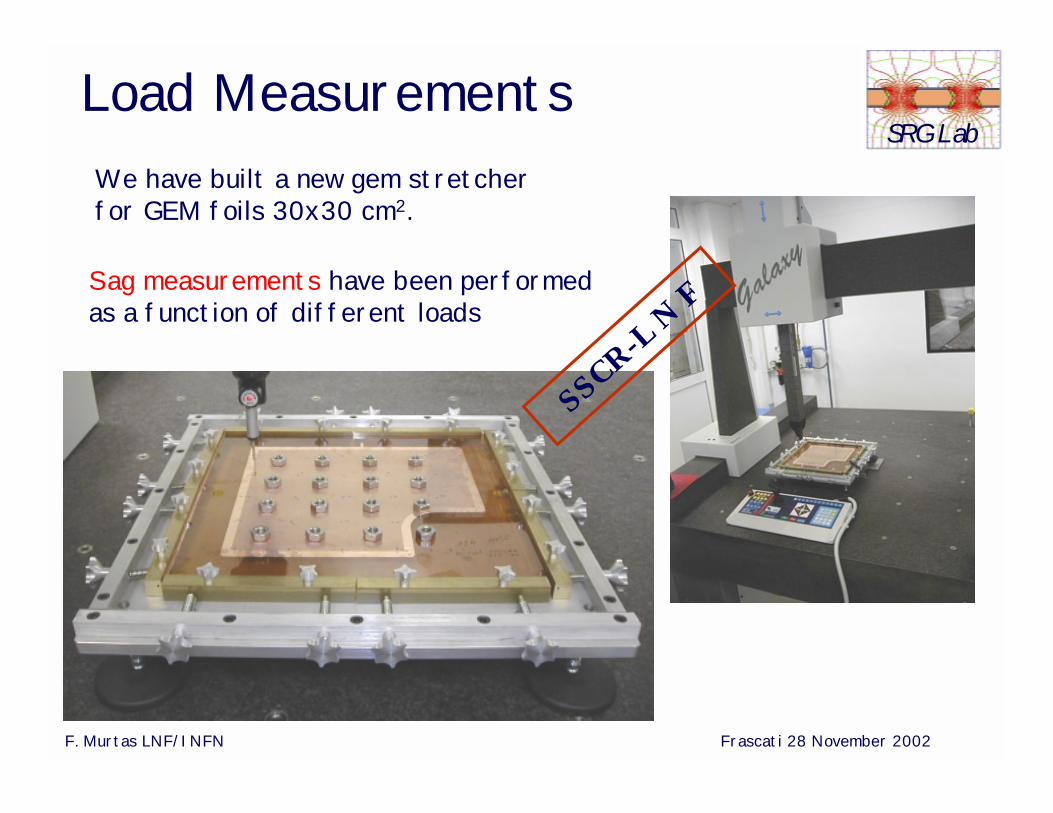
We have built a new gem stretcherfor GEM foils 30x30 cm2.
Load Measurements
Sag measurements have been performedas a function of different loads
SSCR-L N
F
F. Murtas LNF/INFN Frascati 28 November 2002
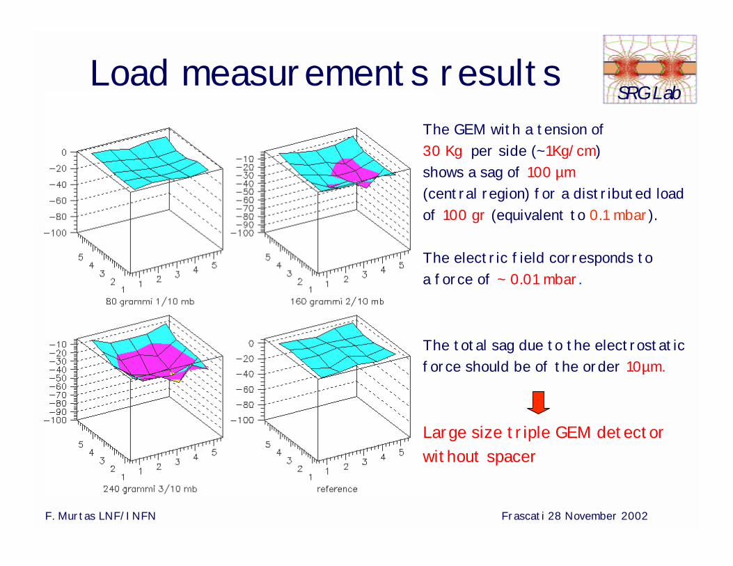
SRG LabLoad measurements results
The total sag due to the electrostatic force should be of the order 10µm.
Large size triple GEM detector without spacer
The GEM with a tension of30 Kg per side (~1Kg/cm) shows a sag of 100 µm(central region) for a distributed load of 100 gr (equivalent to 0.1 mbar).
The electric field corresponds toa force of ~ 0.01 mbar.
F. Murtas LNF/INFN Frascati 28 November 2002
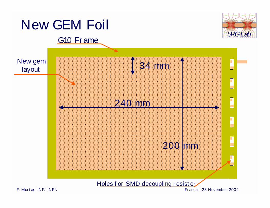
SRG LabNew GEM Foil
200 mm
240 mm
34 mm
Holes for SMD decoupling resistor
G10 Frame
New gemlayout
F. Murtas LNF/INFN Frascati 28 November 2002
SRG Lab
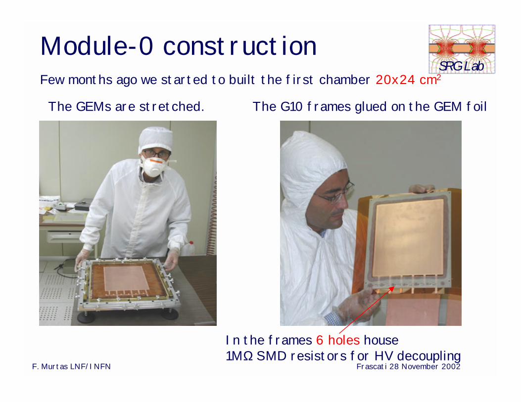
The G10 frames glued on the GEM foil
In the frames 6 holes house1MΩ SMD resistors for HV decoupling
Module-0 constructionFew months ago we started to built the first chamber 20x24 cm2
The GEMs are stretched.
F. Murtas LNF/INFN Frascati 28 November 2002
SRG Lab
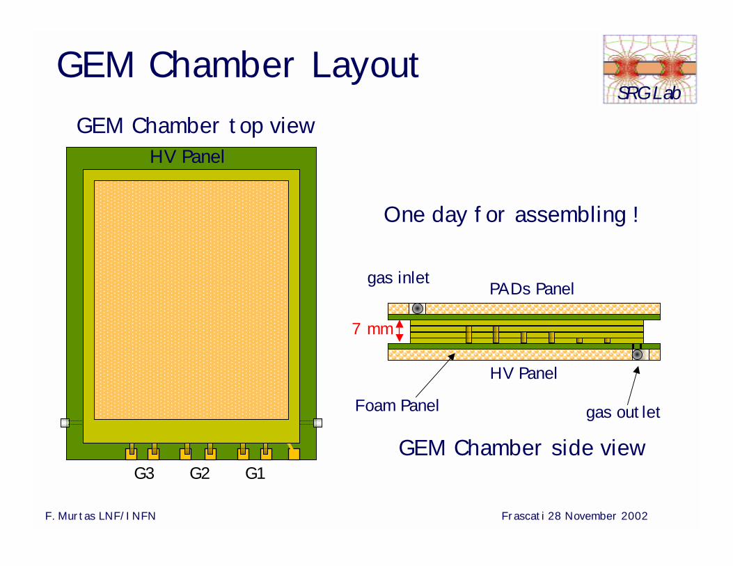
Foam Panel gas outlet
HV Panelgas fitting
HV Panel
GEM Chamber side view
GEM Chamber top view
G1G2G3
PADs Panelgas inlet
7 mm
GEM Chamber Layout
One day for assembling !
F. Murtas LNF/INFN Frascati 28 November 2002
SRG Lab
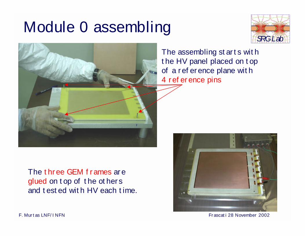
The assembling starts with the HV panel placed on top of a reference plane with 4 reference pins
The three GEM frames are glued on top of the othersand tested with HV each time.
Module 0 assembling
F. Murtas LNF/INFN Frascati 28 November 2002
SRG Lab
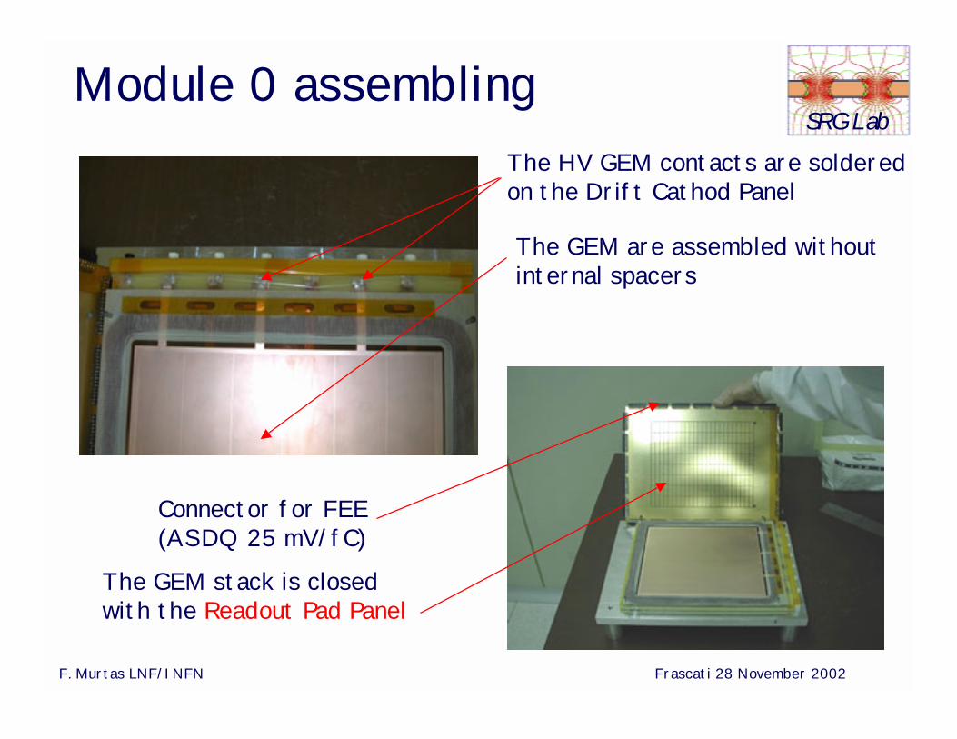
The HV GEM contacts are solderedon the Drift Cathod Panel
The GEM stack is closed with the Readout Pad Panel
Module 0 assembling
The GEM are assembled withoutinternal spacers
Connector for FEE(ASDQ 25 mV/fC)
F. Murtas LNF/INFN Frascati 28 November 2002
SRG Lab
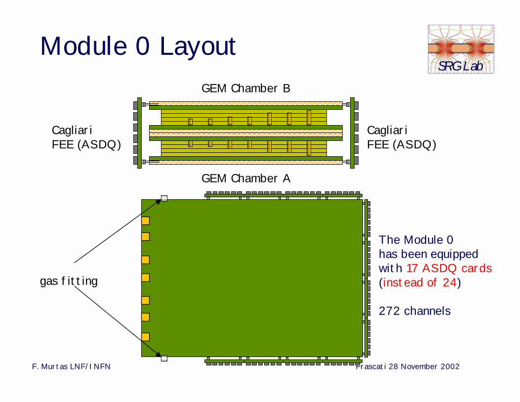
CagliariFEE (ASDQ)
GEM Chamber B
GEM Chamber A
gas fitting
CagliariFEE (ASDQ)
The Module 0 has been equipped with 17 ASDQ cards(instead of 24)
272 channels
Module 0 Layout
F. Murtas LNF/INFN Frascati 28 November 2002
SRG Lab
Cluster size (pads)
chamber A
chamber B
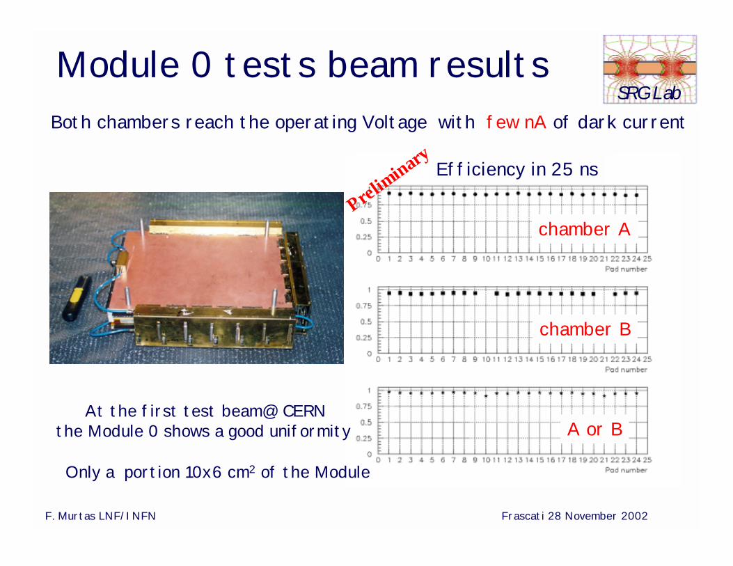
Efficiency in 25 ns
chamber A
chamber B
A or B
Both chambers reach the operating Voltage with few nA of dark current
Module 0 tests beam results
Prelim
inary
At the first test beam@ CERNthe Module 0 shows a good uniformity
Only a portion 10x6 cm2 of the Module
F. Murtas LNF/INFN Frascati 28 November 2002
SRG Lab
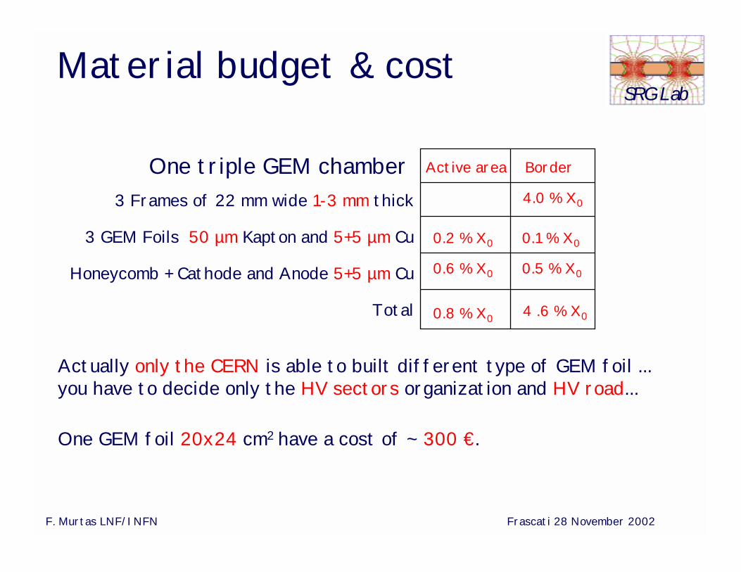
3 Frames of 22 mm wide 1-3 mm thick
3 GEM Foils 50 µm Kapton and 5+5 µm Cu
Honeycomb + Cathode and Anode 5+5 µm Cu
Total
4.0 % X0
0.2 % X0
4 .6 % X0
Material budget & cost
0.1 % X0
BorderActive area
0.8 % X0
One triple GEM chamber
0.6 % X0 0.5 % X0
Actually only the CERN is able to built different type of GEM foil ... you have to decide only the HV sectors organization and HV road...
One GEM foil 20x24 cm2 have a cost of ~ 300 €.
F. Murtas LNF/INFN Frascati 28 November 2002
SRG Lab
Other GEMApplications
F. Murtas LNF/INFN Frascati 28 November 2002
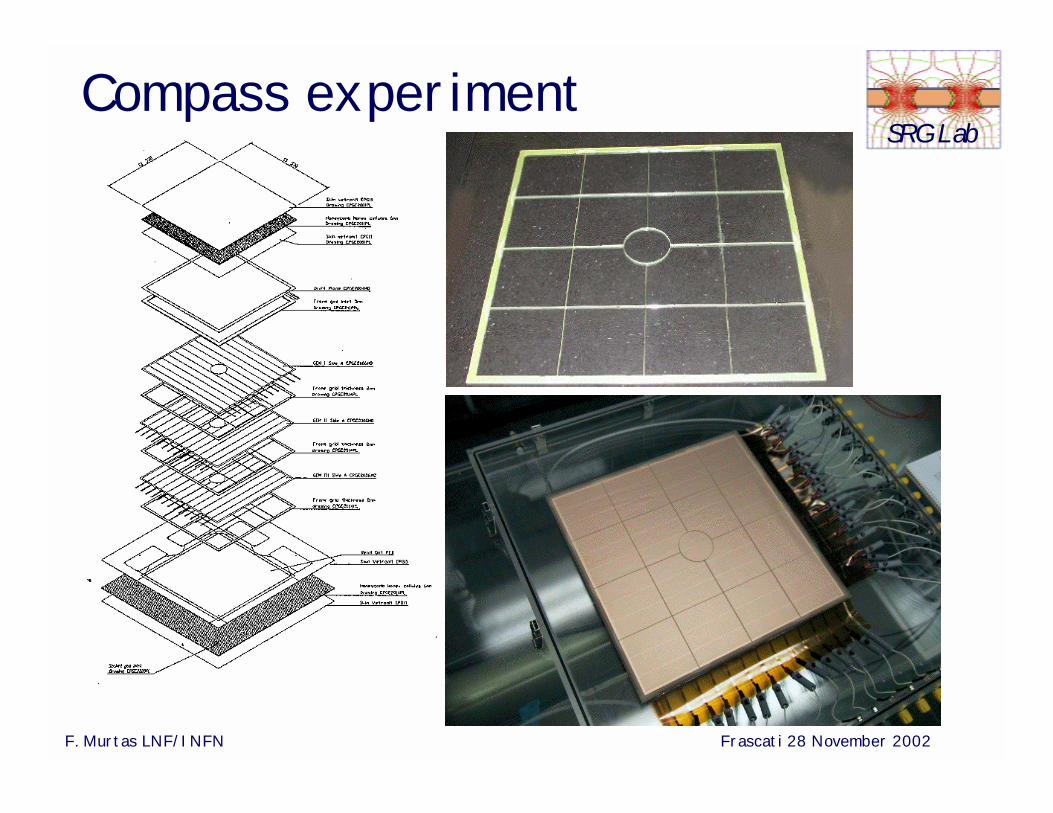
SRG LabCompass experiment
F. Murtas LNF/INFN Frascati 28 November 2002
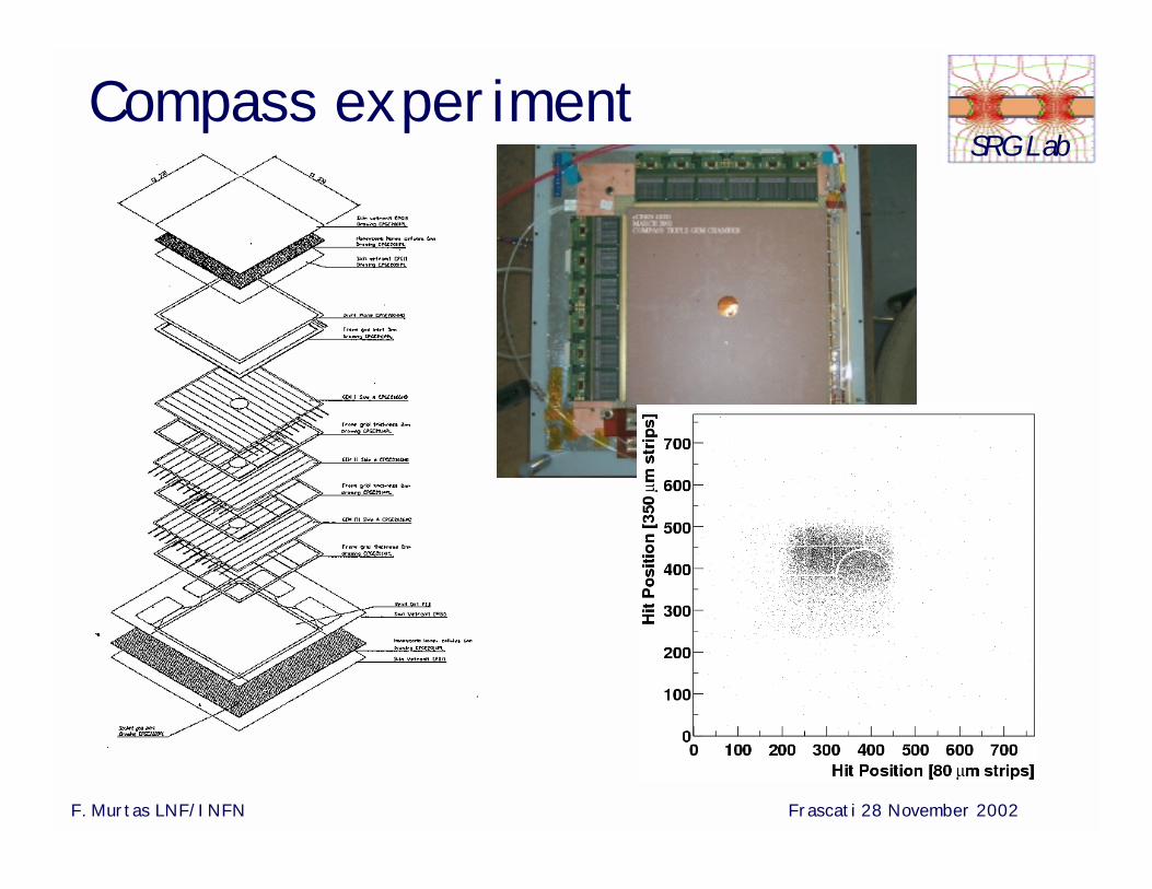
SRG LabCompass experiment
F. Murtas LNF/INFN Frascati 28 November 2002
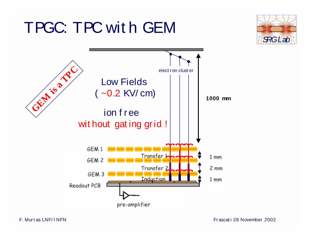
SRG LabTPGC: TPC with GEM
1000 mm
Low Fields ( ~0.2 KV/cm)
ion freewithout gating grid !
electron cluster
GEM is
a TPC
F. Murtas LNF/INFN Frascati 28 November 2002
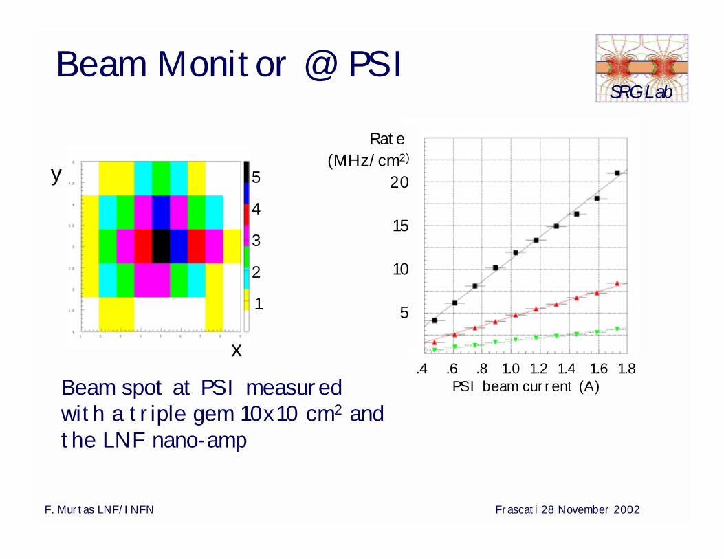
SRG LabBeam Monitor @ PSI
Beam spot at PSI measured with a triple gem 10x10 cm2 and the LNF nano-amp
Rate (MHz/cm2)
20
15
10
5
.4 .6 .8 1.0 1.2 1.4 1.6 1.8PSI beam current (A)
5
4
3
2
1
x
y
F. Murtas LNF/INFN Frascati 28 November 2002
SRG Lab
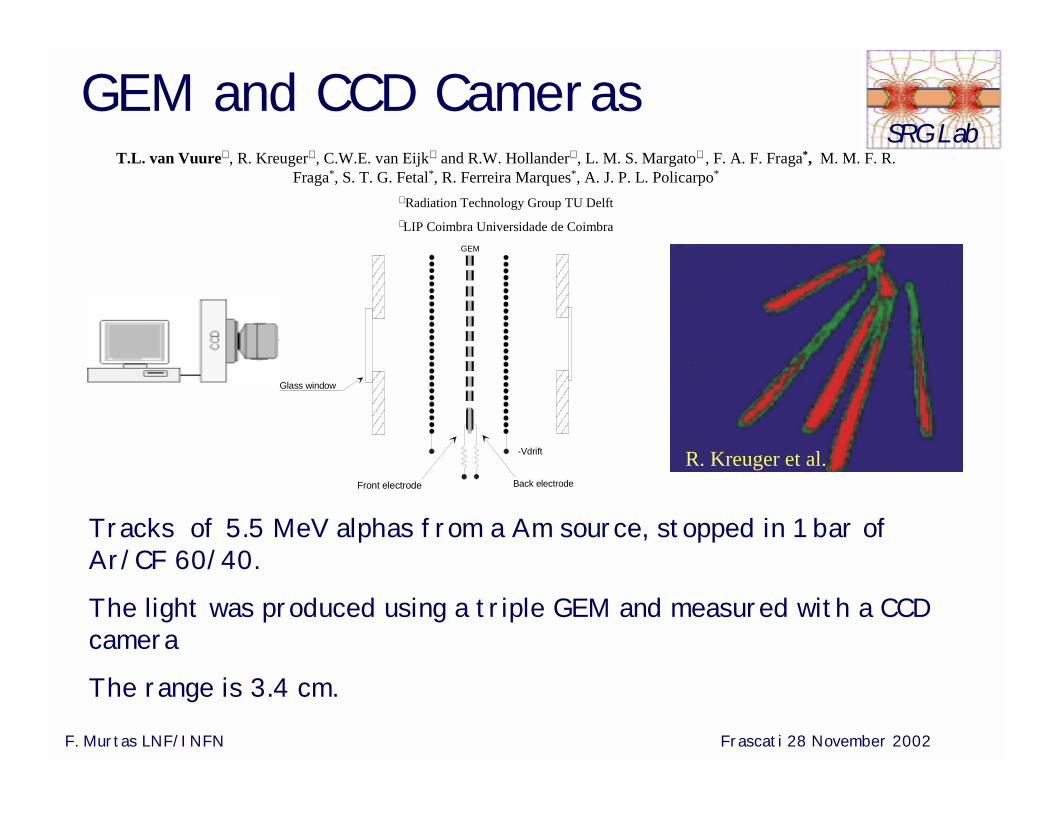
R. Kreuger et al.
Tracks of 5.5 MeV alphas from a Am source, stopped in 1 bar of Ar/CF 60/40.
The light was produced using a triple GEM and measured with a CCD camera
The range is 3.4 cm.
GEM and CCD Cameras
-Vdrift
Front electrode Back electrode
GEM
Glass window
T.L. van Vuure∇ , R. Kreuger∇ , C.W.E. van Eijk∇ and R.W. Hollander∇ , L. M. S. Margato∗ , F. A. F. Fraga*, M. M. F. R. Fraga*, S. T. G. Fetal*, R. Ferreira Marques*, A. J. P. L. Policarpo*
∇ Radiation Technology Group TU Delft∗ LIP Coimbra Universidade de Coimbra
F. Murtas LNF/INFN Frascati 28 November 2002
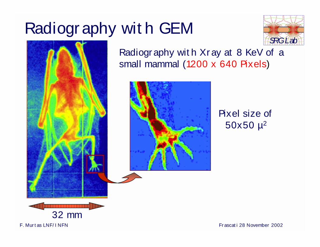
SRG LabRadiography with GEM
Radiography with Xray at 8 KeV of a small mammal (1200 x 640 Pixels)
32 mm
Pixel size of50x50 µ2
F. Murtas LNF/INFN Frascati 28 November 2002
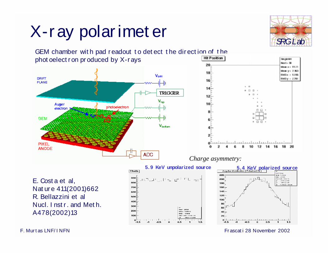
SRG LabX-ray polarimeter
5.9 KeV unpolarized source 5.4 KeV polarized source
GEM chamber with pad readout to detect the direction of the photoelectron produced by X-rays
Charge asymmetry:
E. Costa et al, Nature 411(2001)662R. Bellazzini et alNucl. Instr. and Meth. A478(2002)13
F. Murtas LNF/INFN Frascati 28 November 2002
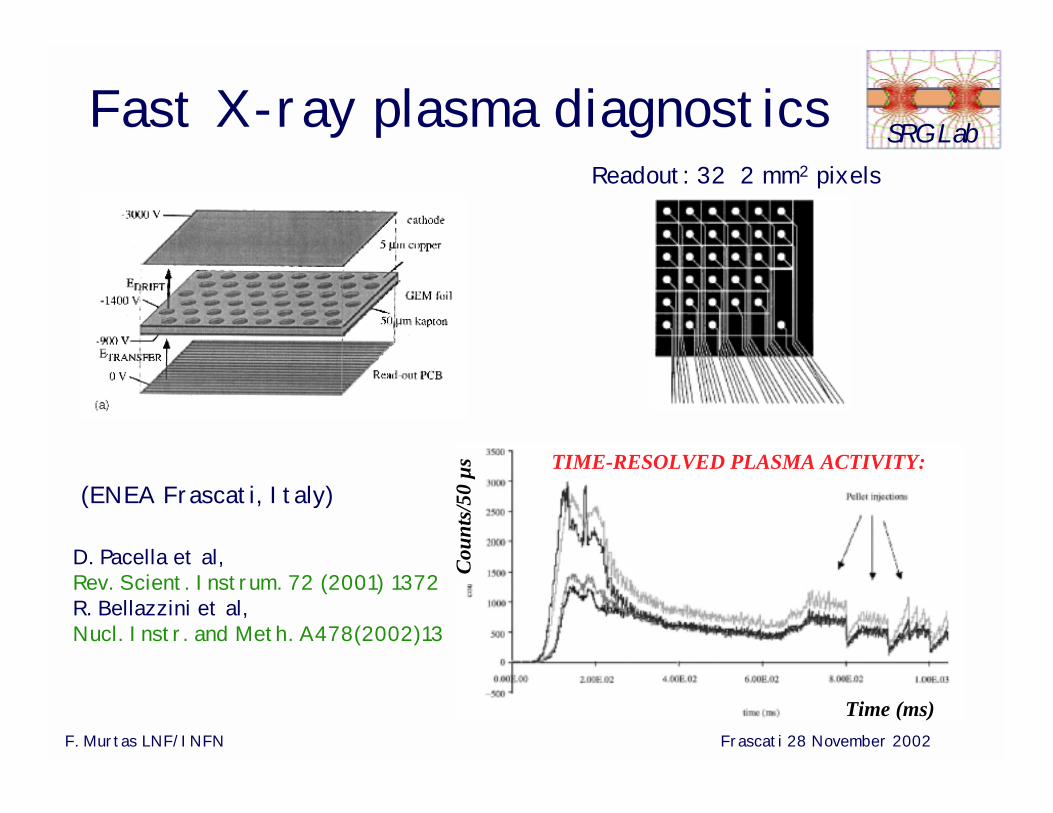
SRG LabFast X-ray plasma diagnostics
(ENEA Frascati, Italy)
Readout: 32 2 mm2 pixels
TIME-RESOLVED PLASMA ACTIVITY:
D. Pacella et al, Rev. Scient. Instrum. 72 (2001) 1372R. Bellazzini et al,Nucl. Instr. and Meth. A478(2002)13
Time (ms)
Coun
ts/5
0 µs
F. Murtas LNF/INFN Frascati 28 November 2002
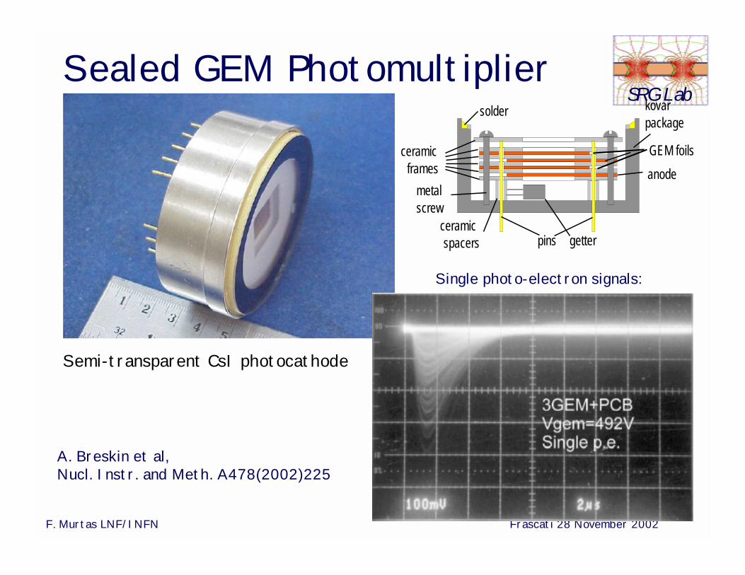
SRG LabSealed GEM Photomultiplier
A. Breskin et al, Nucl. Instr. and Meth. A478(2002)225
Single photo-electron signals:
Semi-transparent CsI photocathode
ceramicspacers
metalscrew
ceramicframes
kovarpackage
solder
GEM foilsanode
pins getter
Continous
x-rays ~60 keV
Pulsed (5 µs) gamma radiation
<50 MeV
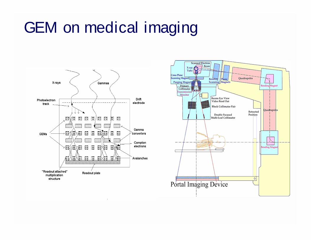
GEM on medical imaging
F. Murtas LNF/INFN Frascati 28 November 2002
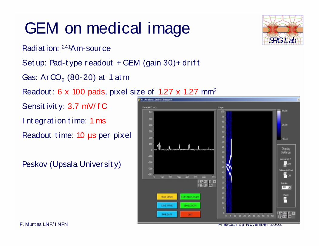
SRG LabGEM on medical image
Radiation: 241Am-source
Setup: Pad-type readout + GEM (gain 30)+ drift
Gas: ArCO2 (80-20) at 1 atm
Readout: 6 x 100 pads, pixel size of 1.27 x 1.27 mm2
Sensitivity: 3.7 mV/fC
Integration time: 1 ms
Readout time: 10 µs per pixel
Peskov (Upsala University)
F. Murtas LNF/INFN Frascati 28 November 2002
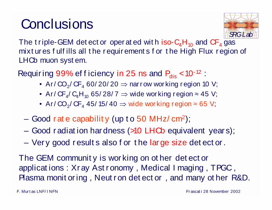
SRG LabConclusions
Requiring 99% efficiency in 25 ns and Pdis < 10-12 :• Ar/CO2/CF4 60/20/20 ⇒ narrow working region 10 V;• Ar/CF4/C4H10 65/28/7 ⇒ wide working region ≈ 45 V;• Ar/CO2/CF4 45/15/40 ⇒ wide working region ≈ 65 V;
The triple-GEM detector operated with iso-C4H10 and CF4 gas mixtures fulfills all the requirements for the High Flux region of LHCb muon system.
– Good rate capability (up to 50 MHz/cm2);– Good radiation hardness (>10 LHCb equivalent years);– Very good results also for the large size detector.
The GEM community is working on other detector applications : Xray Astronomy , Medical Imaging , TPGC , Plasma monitoring , Neutron detector , and many other R&D.