gas discharge tubes (gdt) training material construction and characteristics of gdts performance...
TRANSCRIPT

Gas Discharge Tubes (GDT) Training Material
Construction and Characteristics of GDTs
Performance Ratings
Selection of GDT for Application
Applications when NOT to use GDTs
Comparison of Protective Devices
Page 1

Gas Discharge Tubes
Page 2
A bolt of lightning flashes through the sky and hits the ground somewhere around the world about 100 times every second. That’s 8 million lightning strikes in a single day!
Scientific America- Nov 2014 – Global Warming: New findings suggest lightning strikes may increase by 12% for every degree (°C) of warming … That comes to a 50% increase (in number of lighting strikes) by the end of the century
Gas discharge tubes (GDTs) are ideal for lightning surge protection of electronic equipment, as GDTs can dissipate
large amounts of energy in small size components
Gas discharge tubes (GDTs) are ideal for lightning surge protection of electronic equipment, as GDTs can dissipate
large amounts of energy in small size components
Why are Gas Discharge Tubes
needed?

Electrode
Solder
Ceramic Tube
Gas
Electrode
Carbon line
Ceramic Tube
Electron emission material
Solder
Construction of GDTs
Gas Discharge Tubes
Page 3
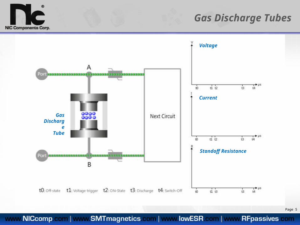
Gas discharge tubes by nature of their construction can handle very large amounts of current, are bidirectional. They have very high impedance and low capacitance, resulting in very little current leakage or signal loss. So the GDT is ‘virtually invisible’ to the protect circuit. GDTs are normally used as primary protection devices, in conjunction with other kinds of protect devices (with faster response speed) as secondary protection. When a surge voltage reaches the GDT spark-over voltage, the GDT will switch into virtual short, divert the surge current through the GDT to ground and removing the voltage surge from damaging the equipment. Therefore, GDTs provide excellent protection during the time period that they are active.

The Townsend discharge is a gas ionization process where free electrons, accelerated by a sufficiently strong electric field, give rise to electrical conduction through a gas by avalanche multiplication, called an Townsend Avalanche. An electron avalanche is a process in which a number of free electrons in a transmission medium (gas) are subjected to strong acceleration by an electric field and subsequently collide with other atoms of the medium, thereby ionizing them (impact ionization). This releases additional electrons which accelerate and collide with further atoms, releasing more electrons—a chain reaction. In a gas, this causes the affected region to become an electrically conductive plasma. The avalanche effect was discovered by John Sealy Townsend in his work between 1897 and 1901, and is also known as the Townsend discharge.
Visualization of a Townsend
Avalanche*
Characteristics of GDTs
Gas Discharge Tubes
Page 4
Gas Discharge Tubes
Page 5
Voltage
Current
Standoff Resistance
Gas Discharge
Tube

Page 6
Gas Discharge Tubes
Typical GDT specification sheet
The following is a review of the GDT specifications

DC Breakdown & Spark-over Voltage
SELECTION GUIDE:With the same DC Breakdown Voltage, the lower the Impulse Spark-Over Voltage, the faster the response speed and the better protection
Part Number
DC Breakdown
Voltage(100V/s)
Breakdown Voltage
Tolerance(V)
ImpulseSpark-Over
Voltage(1KV/μS)
NGTA1812N401TR1F 400V 340~550 ≤750V
NGTC1812N401TR1F 400V 360~560 ≤950V
Page 7
Better protection; lower impulse voltage = faster response
Slower response
The curves (left) show the typical DC breakdown voltage (100V/S) and Impulse Spark-over Voltage (1000V/uS) of NGTA series GDT
Gas Discharge Tubes
Selected based upon operating voltage level (VDC)
The value of Impulse Spark-over Voltage reflects the Gas Discharge
Tube response speed

The arc voltage is developed across the GDT during its “virtual short circuit” condition. This parameter defines the power dissipation of the GDT during its protection mode.
GUIDE: A low arc voltage is desirable to keep power dissipation at a minimum, which in turn increases the life expectancy of the gas discharge tube.
Higher power dissipation (higher operation temperature) will act to reduce the lifetime of the gas discharge tube.
Arc voltage under AC voltage condition
Page 8
Voltage
Current
Gas Discharge Tubes – Arc Voltage
The voltage developed across the GDT component when it is operating is called the “Arc Voltage“ ( Va in above example )
The voltage developed across the GDT component when it is operating is called the “Arc Voltage“ ( Va in above example )
Low Arc Voltage of GDT construction makes the GDT ideal protection against lightning (high-energy) and AC line overvoltage conditions

Solution BSolution A
48VDC solution
Examples: Two solutions (A & B) for 48VDC power port, solution A (above left) uses a special 5-element, 6-terminal GDT. The Arc voltage is >60V@1A, higher than 48VDC, so it is safe choice. Solution B (above right) use a lower voltage single GDT (PN: NGTF2016M091TR5F) in series with a MOV, because the arc voltage of NGTF2016M091TR5F is about 8V@1A, which is lower than the 48VDC system voltage, so it needs to be used in series with a MOV which will claim above 48VDC
Gas Discharge Tubes – Arc Voltage
While low Arc Voltage is desired to minimize power dissipation, the Arc voltage of the GDT in DC circuits should be above the operating voltage level to assure turn off of the GDT. When GDT is used to protect 48VDC power port, the
arc voltage of the gas discharge tube should be selected to be higher than the operating voltage, as shown in Solution ‘A’ below, or used in series with a MOV (such as NIC NVR series) as shown in Solution ‘B’ below
Page 9

NGTA1812N301TR1FNGTA1812N401TR1F
NGTF2016M351TR5FNGTF2016M801TR3FNGTF2016M102TR3FNGTF2016M122TR3F
NGTM2332M351TR20FNGTM2332M471TR20FNGTM2332M601TR20FNGTM2332M801TR20FNGTM2332M152TR10FNGTM2332M362TR10F
NGTD3020M231TR5FNGTD3020M102TR5F
15V 15V 15V 15V
DC12VAC24V
DC12VAC24V
DC12VAC24V
DC12VAC24V
NIC has developed Higher Arc Voltage GDTs, which can be applied in higher voltage DC/AC applications
Format
Part Number
Application
Arc Voltage
Arc Voltage at 1A
Gas Discharge Tubes – Arc Voltage
Page 10
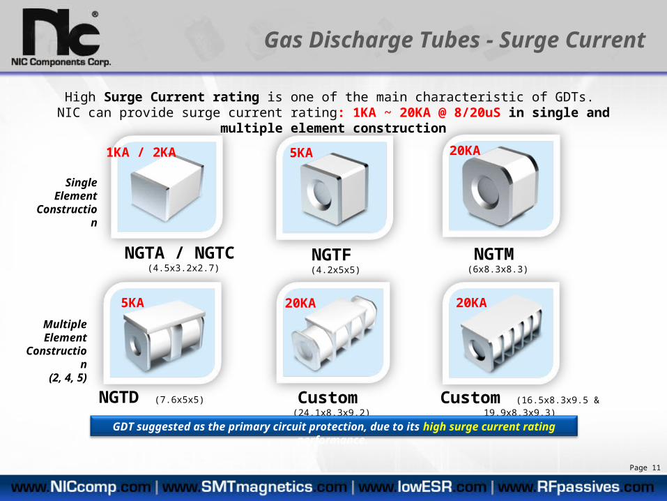
NGTA / NGTC (4.5x3.2x2.7)
NGTD (7.6x5x5) Custom (24.1x8.3x9.2) Custom (16.5x8.3x9.5 & 19.9x8.3x9.3)
NGTF (4.2x5x5) NGTM (6x8.3x8.3)
High Surge Current rating is one of the main characteristic of GDTs. NIC can provide surge current rating: 1KA ~ 20KA @ 8/20uS in single and multiple element construction
GDT suggested as the primary circuit protection, due to its high surge current rating performance.
Gas Discharge Tubes - Surge Current
1KA / 2KA 5KA
5KA 20KA 20KA
20KA
Single Element
Construction
Multiple Element
Construction(2, 4, 5)
Page 11
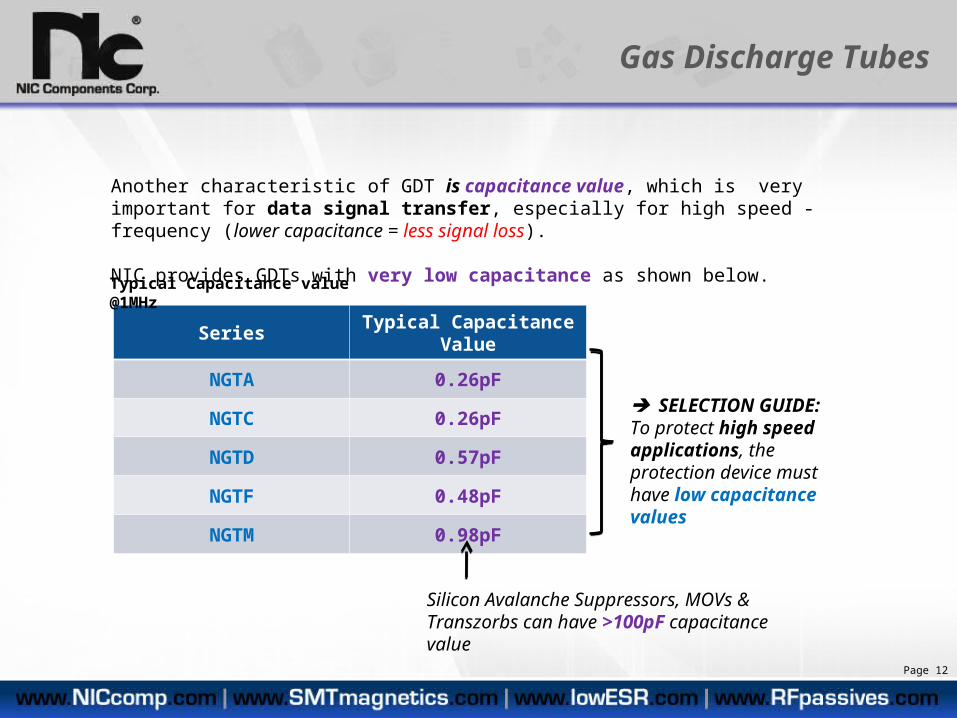
Series Typical Capacitance Value
NGTA 0.26pF
NGTC 0.26pF
NGTD 0.57pF
NGTF 0.48pF
NGTM 0.98pF
Another characteristic of GDT is capacitance value, which is very important for data signal transfer, especially for high speed - frequency (lower capacitance = less signal loss).
NIC provides GDTs with very low capacitance as shown below.
Typical Capacitance value @1MHz
Gas Discharge Tubes
SELECTION GUIDE:To protect high speed applications, the protection device must have low capacitance values
Page 12
Silicon Avalanche Suppressors, MOVs & Transzorbs can have >100pF capacitance value

Parameters - Characteristics of GDTs
Gas Discharge Tubes
Lower is betterLower is better
Higher is betterHigher is better
Selection based upon operating voltage Selection based upon operating voltage Guidance based upon application
VAC or VDC
Guidance based upon application
VAC or VDC
Page 13
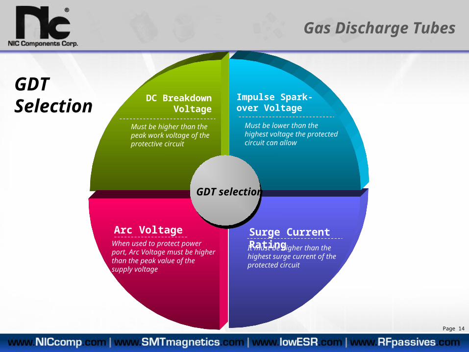
GDT Selection
GDT selection
When used to protect power port, Arc Voltage must be higher than the peak value of the supply voltage
DC Breakdown Voltage
Must be higher than the peak work voltage of the protective circuit
It must be higher than the highest surge current of the protected circuit
Impulse Spark-over Voltage
Must be lower than the highest voltage the protected circuit can allow
Arc Voltage Surge Current Rating
Gas Discharge Tubes
Page 14

GDTs are suggested for use in primary protection, but not suggested for use in secondary or ESD protectionGDTs are suggested for use in primary protection, but not suggested for use in secondary or ESD protection
Primary Protection:GDT
Example: Tip & Ring xDSL protection solution
Low response speed
High residual voltage
High surge current rating Good for large surge current protection Use in primary protection
Not suggested for fine protectionNot used in secondary or ESD protection
Gas Discharge Tubes
Secondary or ESD Protection TVS
Page 15

GDTArc voltage 15V@1A
12VDC solution
L
+12V
0V
Gas Discharge Tubes
When GDT is used in power port, need to be cautious in selection of GDT. Must ensure the GDT can shut off after surge wave has passed. The arc voltage of the GDT should be
selected higher than the circuit voltage, or use the GDT in series with a MOV.
When GDT is used in power port, need to be cautious in selection of GDT. Must ensure the GDT can shut off after surge wave has passed. The arc voltage of the GDT should be
selected higher than the circuit voltage, or use the GDT in series with a MOV.
Secondary Protection TVS
Page 16

GDT – Gas Discharge Tube
TSS - Thyristor Surge Suppressors
TVS - Transient Voltage Suppressor
MOV - Metal Oxide Varistor
Operating Principle
Gas discharge Avalanche effect of PN junction
Avalanche effect of PN junction
Nonlinear voltage characteristic
Protection Mode
Switch Mode Switch Mode Clamp Mode Clamp Mode
Response speed Slow Fast Very fast Medium
Ability of withstand high
voltageHigh Medium Low Medium--High
Leakage Very low <5uA <5-10uA <20-30uA
Capacitance Very low, normally lower than 1pF
Mid (be related to lightning level)
Mid (be related to lightning level)
Large (be relate to the size and
lighting level)
Failure Mode Open Short Short Short
DeviceDeviceItemItem
Comparison of Over-Voltage Protective Devices
Page 17

Switch Mode
Clamp Mode
TVS - Transient Voltage
Suppressor
MOV - Metal Oxide Varistor
TSS - Thyristor
Surge Suppressor
GDT – Gas Discharge
Tube
Comparison of Over-Voltage Protective Devices
Page 18

Comparison of Over-Voltage Protective Devices
GDT – Gas Discharge Tube
TSS - Thyristor Surge Suppressors
TVS - Transient Voltage Suppressor
MOV - Metal Oxide Varistor
Advantage
High Surge Current Rating,
Low Capacitance, Low Leakage
Low Residual Voltage, Fast Response Speed,
High Accuracy of Voltage
Low Residual Voltage, Fast Response
Speed, High Accuracy of
Voltage
High Accuracy of Voltage,
Low cost
Disadvantage High Residual Voltage, Slower Response Speed
Limited Voltage Range,
Can Not Be Used In Power supply Port
Low Surge Current Rating,
Unit cost increases with Surge Current
Rating Increase
High Capacitance,Easy Degenerate,
Large Leakage
Typical Usage Applications
Mainly used to primary protection of signal ports with high flow capability
or low voltage power supply ports
Mainly used primary or secondary protection of
signal ports, Normally not used in power supply ports
Mainly used for fine protection, such as
secondary, third level protection and ESD
protection
Mainly used in power supply ports, normally not used in signal ports
due to its’ high capacitance.
Page 19
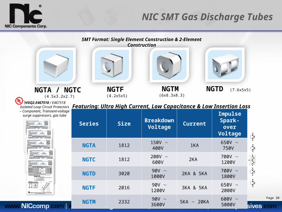
NGTA / NGTC (4.5x3.2x2.7) NGTD (7.6x5x5)NGTF (4.2x5x5) NGTM (6x8.3x8.3)
NIC SMT Gas Discharge Tubes
SMT Format: Single Element Construction & 2-Element Construction
Series Size BreakdownVoltage Current
Impulse Spark-over
Voltage
NGTA 1812 150V 400V 1KA 650V 750V
NGTC 1812 200V 600V 2KA 700V 1200V
NGTD 3020 90V 1000V 2KA & 5KA 700V 1800V
NGTF 2016 90V 1200V 3KA & 5KA 650V 2000V
NGTM 2332 90V 3600V 5KA 20KA 600V 5000V
Featuring: Ultra High Current, Low Capacitance & Low Insertion LossQVGQ2.E467518 / E467518
Isolated Loop Circuit Protectors – Component, Transient-voltage
surge suppressors, gas tube
Page 20
NIC SMT Gas Discharge Tubes
Page 21
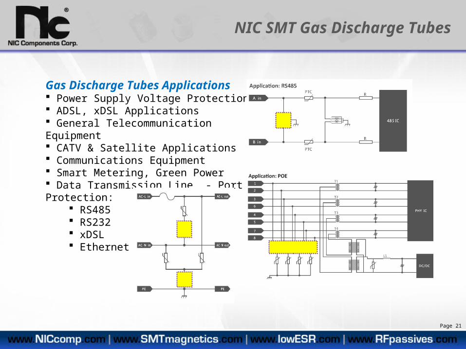
Gas Discharge Tubes Applications Power Supply Voltage Protection ADSL, xDSL Applications General Telecommunication Equipment CATV & Satellite Applications Communications Equipment Smart Metering, Green Power Data Transmission Line - Port Protection:
RS485 RS232 xDSL Ethernet

Page 22
NIC Circuit Protection Products
NFVC Series Chip Fuse
Over-current Protection
NPX Series X2 CapacitorInterference Suppression
NVR Series Metal Oxide Varistor (MOV)Over-voltage protection
NGT_ Series Gas Discharge TubesOver-voltage Protection
NIC Circuit Protection Products→ NGT_ - SMT Gas Discharge Tubes→ NVR – MOV High Voltage Varistors→ NPX– X2 Safety Capacitors→ NFVC – 125V / 250VAC Chip Fuses
NIC Circuit Protection Products→ NGT_ - SMT Gas Discharge Tubes→ NVR – MOV High Voltage Varistors→ NPX– X2 Safety Capacitors→ NFVC – 125V / 250VAC Chip Fuses

Additional Information Needed?Need Samples?
Additional Information Needed?Need Samples?
NIC Components offers unique performance passive components that provide advantages to design engineers to create high performance end products in smaller and lower total cost formats
• Surface Mount SMT formats (high speed auto placement)• Pb-Free Reflow Compatible (high temperature reflow) • Performance advantages over competing technologies
Technical Support: [email protected]
Sales Support: [email protected]
Technical Support: [email protected]
Sales Support: [email protected]
North America Engineering Support
SE Asia Engineering Support
European Engineering Support
Page 23