gas book honeywell analytics experts in gas detection - apc
TRANSCRIPT
Gas book
Honeywell AnalyticsExperts in Gas Detection
� www.honeywellanalytics.com
1 Honeywell Analytics
As the gas detection experts, Honeywell Analytics brings together nearly 200 collective years of expertise in design, manufacture and technology. In fact, many of the company’s product ranges have now become the industry term for gas detection, such as Sieger and MDA. The company also enjoys a glittering array of accolades including being the originators of an impressive number of technological firsts.
Adaptability and innovation are key themes at Honeywell Analytics. The company’s comprehensive product range has an option suited to every type of application or industry. In addition, a strong commitment to service and understanding the unique needs of its customers ensures that
Honeywell Analytics remains the premier provider of gas detection solutions, and a name that is synonymous with excellence.In addition to the extensive product range, Honeywell Analytics also provides a number of authoritative platforms, providing a comprehensive offering of knowledge, expertise and information on every aspect of gas detection. These include the website www.honeywellanalytics.com known as the definitive resource for anyone wanting to learn more about the subject in its entirety.
Honeywell Analytics – Experts in gas Detection
Honeywell Analytics is not only the market leading supplier of gas detection equipment and accessories, but a pioneering force behind the industry with an unrivalled offering of technical expertise. The Honeywell Analytics ethos is strong and simple – to provide a panoptic resource for all things gas detection related and to set the benchmark for standards and expertise in the industry.

�
Honeywell Analytics’ commitment to excellence is reflected in our dedication to best practise in customer relations. By adopting a cohesive, unified approach to all aspects of customer relations and service, all enquiries, sales, service and technical support are handled by two ‘customer business centers’ located in Uster, Switzerland and Sunrise, Florida, ensuring our customers receive the high level of advice and support they deserve.
We are a responsible company and take pride in building positive, sustained relationships with all our stakeholders. By the very nature of our business, we are an environmentally-aware company and our working and manufacturing methods reflect this commitment to good environmental practise.

Industrial processes increasingly involve the use and manufacture of highly dangerous substances, particularly flammable, toxic and oxygen gases. Inevitably, occasional escapes of gas occur, which create a potential hazard to the industrial plant, its employees and people living nearby. Worldwide incidents, involving asphyxiation, explosions and loss of life, are a constant reminder of this problem.
In most industries, one of the key parts of any safety plan for reducing risks to personnel and plant is the use of early-warning devices such as gas detectors. These can help to provide more time in which to take remedial or protective action. They can also be used as part of a total, integrated monitoring and safety system for an industrial plant.
� www.honeywellanalytics.com
� Introduction
This handbook is intended to offer a simple guide to anyone considering the use of such gas detection equipment. It provides an explanation of both the principles involved and the instrumentation needed for satisfactory protection of personnel, plant and environment. The aim has been to answer as many as possible of the most commonly asked questions about the selection and use of industrial gas detection equipment.
�
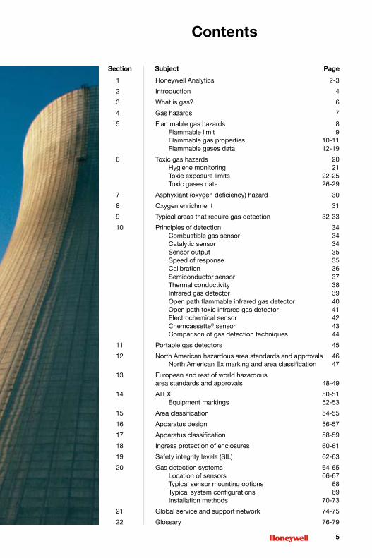
Contents
1 Honeywell Analytics 2-3
2 Introduction 4
3 What is gas? 6
4 Gas hazards 7
5 Flammable gas hazards 8 Flammable limit 9 Flammable gas properties 10-11 Flammable gases data 12-19
6 Toxic gas hazards 20 Hygiene monitoring 21 Toxic exposure limits 22-25 Toxic gases data 26-29
7 Asphyxiant (oxygen deficiency) hazard 30
8 Oxygen enrichment 31
9 Typical areas that require gas detection 32-33
10 Principles of detection 34 Combustible gas sensor 34 Catalytic sensor 34 Sensor output 35 Speed of response 35 Calibration 36 Semiconductor sensor 37 Thermal conductivity 38 Infrared gas detector 39 Open path flammable infrared gas detector 40 Open path toxic infrared gas detector 41 Electrochemical sensor 42 Chemcassette® sensor 43 Comparison of gas detection techniques 44
11 Portable gas detectors 45
12 North American hazardous area standards and approvals 46 North American Ex marking and area classification 47
13 European and rest of world hazardous area standards and approvals 48-49
14 ATEX 50-51 Equipment markings 52-53
15 Area classification 54-55
16 Apparatus design 56-57
17 Apparatus classification 58-59
18 Ingress protection of enclosures 60-61
19 Safety integrity levels (SIL) 62-63
20 Gas detection systems 64-65 Location of sensors 66-67 Typical sensor mounting options 68 Typical system configurations 69 Installation methods 70-73
21 Global service and support network 74-75
22 Glossary 76-79
Section Subject Page

Different gases are all around us in everyday life. The air we breathe is made up of several different gases including Oxygen and Nitrogen.
Natural Gas (Methane) is used in many homes for heating and cooking.
Vehicle engines combust fuel and Oxygen and produce exhaust gases that include Nitrogen Oxides, Carbon Monoxide and Carbon Dioxide.
Gases can be lighter, heavier or about the same density as air. Gases can have an odour or be odourless. Gases can have colour or be colourless. If you can’t see it, smell it or touch it, it doesn’t mean that it is not there.
� www.honeywellanalytics.com
� What is Gas?
The name gas comes from the word chaos. Gas is a swarm of molecules moving randomly and chaotically, constantly colliding with each other and anything else around it. Gases fill any available volume and due to the very high speed at which they move will mix rapidly into any atmosphere in which they are released.
SO2
HCN
HCNCH4
CH4
CH4
C2H6
ClO2
O2
PH3H2S
CH3COCH3C6H14
H2S
NO2
C4H10
H2S
C3H8
SO2
SO2
WF6NH3
SO2
SO2
CO2
CO2
NH3
H2C:CH2
NH3
CO
CO
CO
CO2
CO2
B2H6
NO
NO2
CH4
C4H6
SO2
SO2
SO2
SO2
SO2
NO2
NO2
HCN
C4H10
C2H6
H2S
H2S
ClO2 PH3
ClO2
HCN
O2
O3
CH3CH2OH
BF3
HCN
Cl2
C3H8
C6H14
COCl2 PH3
PH3
HCN
NH3
NH3 CO
COSO2
SiH2Cl2
HCN
CH2-CH2-O
Cl2
C6H12
SO2
SO2
SO2
SO2
SiH2Cl2
CO2
CO2
CO
CO CO
Si(OCH2CH3)4
BF3
CO2C6H6
CO2
CO2
BF3
N2C:CH2
NO2
NO2
CH4
C6H4(CH3)2
SO2 SO2
SO2
SO2
SO2
SO2
O2
SO2
SiH2Cl2
H2SH2S
H2S
PH3
PH3
PH3
PH3
ClO2
C6H5CH=CH2
WF6
HCN
CH3(CH2)CH3
H2S
NO2
C3H8C3H8
ClO2
CH3(CH2)6CH3
SO2
SO2
SO2
O2
CH4
CH4
CH4
CH4
CO
O2
HCON(CH3)2
O2
CH3[CH2]5CH3
O2
O3
O3
WF6
O3
NH3
NH3
CO
CO2
C6H6
NO2
NO2
NO2
H2S
HCl
TEOS
NO2
CO
PH3
ClO2
ClO2
ClO2
PH3
CO2
CO2
NH3
CH2-CH2-O
CH4
Cl2
Cl2 ClO2
PH3
CO
CO
HCN
CH4
CH4
ClO2
PH3PH3
CIO2 H2
Cl2 Cl2SO2
SO2
SO2
SO2
SO2 NO
B2H6
B2H6
SO2
NO2
H2C:CH2
C4H10
C4H10
C2H6
H2S
H2S
H2S
H2S HCl
HCN
O2
C4H10
HCN
HCl
HCN
C6H5CH3
SO2
CO2
CH4
B2H6
C3H8
CH4
WF6
CH4
POCl2
BF3
PH3
PH3ClO2
HCN
CO2
B2H6
C6H6
CO2
COCl2
SO2SO2
SO2
SO2
CO2CH3COCH3
CH3[CH2]5CH3CH3COCH3
CO2
NO2
NO2
CH4CO2
SO2
SO2
SO2
H2S
PH3
PH3
PH3
PH3
O2
O2
CO2
C4H10
C4H10
TEOS
CH3(CH2)6CH3
C6H14
H2SNH3
CH3COO[CH2]3CH3
TEOS
CH3(CH2)6CH3
CH3(CH2)6CH3
CO
C3H8
C3H8
SO2
NH3CH3COCH3
CH4
H2S
PH3
CIO2
O2
C6H5CH3
CO2
C6H12
HCN
HCl
CH3:CHCH3
COCl2
H2S
NH3
Si(OCH2CH3)4
CH2-CH2-O
C3H8
O2
O2
NH3
NO2 NO
CH3(CH2)6CH3
SO2
HCN
CH2(CH2)3CH3
C4H10
CH4
H2S
C3H10
C3H8
C3H8
Cl2 CH3CH2OH
CH3:CHCH3NO2
WF6
B2H6
CH3(CH2)6CH3
CH3CH2OHCH3(CH2)6CH3
CH3(CH2)6CH3
CH3:CHCH3
H2
SiH4
Si2H6
HF
AsH3
H2Se
H2HBr
H2
Si2H6
HF
GeH4
GeH4
Si2H6
F2
F2
H2Se
SiH4
GeH4
HF
H2
BCl3
BCl3
H2HBr
HBr
BR2
GeH4
BR2
Br2
PH3
CH3COO[CH2]3CH3
CH3COO[CH2]3CH3
C6H12
C6H12
C6H12
C6H5CH3
C6H5CH=CH2
C6H5CH=CH2
C6H4(CH3)2
C6H4(CH3)2
CH3[CH2]5CH3
CH3[CH2]5CH3
CH3[CH2]5CH3
CH3(CH2)6CH3
CH3(CH2)6CH3
CH3(CH2)6CH3
CH3(CH2)6CH3
C2H5OC2H5C2H5OC2H5
HCON(CH3)2
HCON(CH3)2
HCON(CH3)2
POCl2
POCl2
POCl2
Name Symbol PercentbyVolume
Nitrogen N2 78.084%
Oxygen O2 20.9476%
Argon Ar 0.934%
CarbonDioxide CO2 0.0314%
Neon Ne 0.001818%
Methane CH4 0.0002%
Helium He 0.000524%
Krypton Kr 0.000114%
Hydrogen H2 0.00005%
Xeron Xe 0.0000087%
The table gives the sea-level composition of air (in percent by volume at the temperature of 15°C and the pressure of 101325 Pa).
AirComposition
�
� Gas Hazards
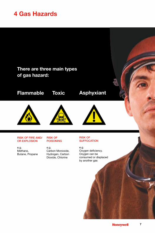
There are three main types of gas hazard:
Flammable
Risk of fiRe and/ oR explosion
e.g. Methane, Butane, Propane
Toxic
Risk of poisoning
e.g. Carbon Monoxide, Hydrogen, Carbon Dioxide, Chlorine
Asphyxiant
Risk of suffocation
e.g. Oxygen deficiency. Oxygen can be consumed or displaced by another gas
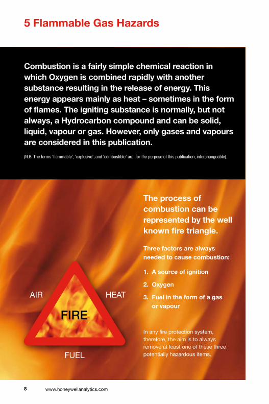
Combustion is a fairly simple chemical reaction in which Oxygen is combined rapidly with another substance resulting in the release of energy. This energy appears mainly as heat – sometimes in the form of flames. The igniting substance is normally, but not always, a Hydrocarbon compound and can be solid, liquid, vapour or gas. However, only gases and vapours are considered in this publication.
(N.B. The terms ‘flammable’, ‘explosive’, and ‘combustible’ are, for the purpose of this publication, interchangeable).
The process of combustion can be represented by the well known fire triangle.
Three factors are always needed to cause combustion:
1. A source of ignition
�. Oxygen
�. Fuel in the form of a gas or vapour
In any fire protection system, therefore, the aim is to always remove at least one of these three potentially hazardous items.
� www.honeywellanalytics.com
� Flammable Gas Hazards
fiRe
AIR HEAT
FUEL

At levels below the LEL, there is insufficient gas to produce an explosion (i.e. the mixture is too ‘lean’), whilst above the UEL, the mixture has insufficient Oxygen (i.e. the mixture is too ‘rich’). The flammable range therefore falls between the limits of the LEL and UEL for each individual gas or mixture of gases. Outside these limits, the mixture is not capable of combustion. The Flammable Gases Data in section 2.4 indicates the limiting values for some of the better-known combustible gases and compounds. The data is given for gases and vapours at normal conditions of pressure and temperature. An increase in pressure, temperature or Oxygen content will generally broaden the flammability range.
In the average industrial plant, there would normally be no gases leaking into the surrounding area or, at worst, only a low background level of gas present. Therefore
�
Flammable Limit
There is only a limited band of
gas/air concentration which will
produce a combustible mixture.
This band is specific for each gas
and vapour and is bounded by an
upper level, known as the Upper
Explosive Limit (or the UEL) and
a lower level, called the Lower
Explosive Limit (LEL).
the detecting and early warning system will only be required to detect levels from zero percent of gas up to the lower explosive limit. By the time this concentration is reached, shut-down procedures or site clearance should have been put into operation. In fact this will typically take place at a concentration of less than 50 percent of the LEL value, so that an adequate safety margin is provided.
However, it should always be remembered that in enclosed or unventilated areas, a concentration in excess of the UEL can sometimes occur. At times of inspection, therefore, special care needs to be taken when operating hatches or doors, since the ingress of air from outside can dilute the gases to a hazardous, combustible mixture.
(N.B LEL/LFL and UEL/UFL are, for the purpose of this publication, interchangeable).
Too rich
Flammable range
Too lean
100% v/v gas0% v/v air
U.E.L. (upper explosive limit)
L.E.L. (lower explosive limit)
0% v/v gas100% v/v air
10 www.honeywellanalytics.com
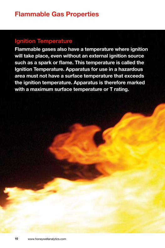
Ignition TemperatureFlammable gases also have a temperature where ignition will take place, even without an external ignition source such as a spark or flame. This temperature is called the Ignition Temperature. Apparatus for use in a hazardous area must not have a surface temperature that exceeds the ignition temperature. Apparatus is therefore marked with a maximum surface temperature or T rating.
Flammable Gas Properties
11
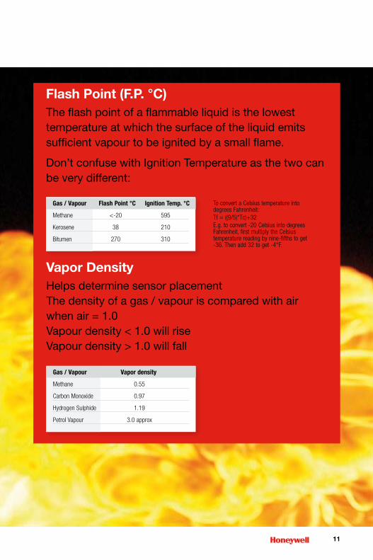
Vapor DensityHelps determine sensor placementThe density of a gas / vapour is compared with air when air = 1.0Vapour density < 1.0 will riseVapour density > 1.0 will fall
Gas/Vapour FlashPoint°C IgnitionTemp.°C
Methane <-20 595
Kerosene 38 210
Bitumen 270 310
Flash Point (F.P. °C)The flash point of a flammable liquid is the lowest temperature at which the surface of the liquid emits sufficient vapour to be ignited by a small flame.
Don’t confuse with Ignition Temperature as the two can be very different:
Gas/Vapour Vapordensity
Methane 0.55
CarbonMonoxide 0.97
HydrogenSulphide 1.19
PetrolVapour 3.0approx
ToconvertaCelsiustemperatureintodegreesFahrenheit:Tf=((9/5)*Tc)+32E.g.toconvert-20CelsiusintodegreesFahrenheit,firstmultiplytheCelsiustemperaturereadingbynine-fifthstoget-36.Thenadd32toget-4°F.
1� www.honeywellanalytics.com
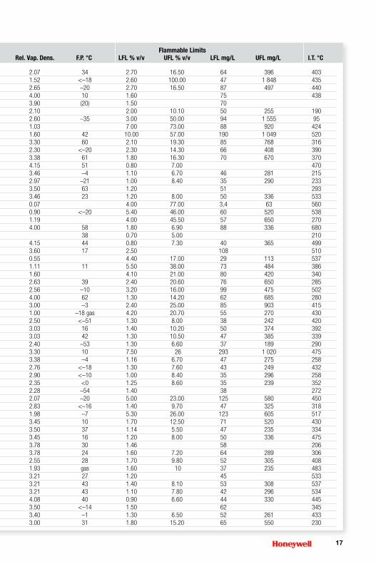
Flammable Gases Data
FlammableLimits CommonName CASNumber Formula Mol.Wt. B.P.°C Rel.Vap.Dens. F.P.°C LFL%v/v UFL%v/v LFLmg/L UFLmg/L I.T.°C
Acetaldehyde 75-07-0 CH3CHO 44.05 20 1.52 –38 4.00 60.00 74 1108 204 Aceticacid 64-19-7 CH3COOH 60.05 118 2.07 40 4.00 17.00 100 428 464Aceticanhydride 108-24-7 (CH3CO)2O 102.09 140 3.52 49 2.00 10.00 85 428 334Acetone 67-64-1 (CH3)2CO 58.08 56 2.00 <–20 2.50 13.00 80 316 535 Acetonitrile 75-05-8 CH3CN 41.05 82 1.42 2 3.00 16.00 51 275 523Acetylchloride 75-36-5 CH3COCl 78.5 51 2.70 –4 5.00 19.00 157 620 390 Acetylene 74-86-2 CH=CH 26 -84 0.90 2.30 100.00 24 1092 305Acetylfluoride 557-99-3 CH3COF 62.04 20 2.14 <–17 5.60 19.90 142 505 434 Acrylaldehyde 107-02-8 CH2=CHCHO 56.06 53 1.93 –18 2.85 31.80 65 728 217 Acrylicacid 79-10-7 CH2=CHCOOH 72.06 139 2.48 56 2.90 85 406Acrylonitrile 107-13-1 CH2=CHCN 53.1 77 1.83 –5 2.80 28.00 64 620 480 Acryloylchloride 814-68-6 CH2CHCOCl 90.51 72 3.12 –8 2.68 18.00 220 662 463 Allylacetate 591-87-7 CH2=CHCH2OOCCH3 100.12 103 3.45 13 1.70 9.30 69 3800 348Allylalcohol 107-18-6 CH2=CHCH2CH 58.08 96 2.00 21 2.50 18.00 61 438 378Allylchloride 107-05-1 CH2=CHCH2Cl 76.52 45 2.64 –32 2.90 11.20 92 357 390Ammonia 7664-41-7 NH3 17 -33 0.59 15.00 33.60 107 240 630Aniline 62-53-3 C6H6NH2 93.1 184 3.22 75 1.20 11.00 47 425 630Benzaldehyde 100-52-7 C6H5CHO 106.12 179 3.66 64 1.40 62 192Benzene 71-43-2 C6H6 78.1 80 2.70 –11 1.20 8.60 39 280 560 1-Bromobutane 109-65-9 CH3(CH2)2CH2Br 137.02 102 4.72 13 2.50 6.60 143 380 265Bromoethane 74-96-4 CH3CH2Br 108.97 38 3.75 <–20 6.70 11.30 306 517 511 Buta-1,3-diene 106-99-0 CH2=CHCH=CH2 54.09 -4.5 1.87 -76 1.40 16.30 31 365 430Butane 106-97-8 C4H10 58.1 -1 2.05 1.40 9.30 33 225 372Isobutane 75-28-5 (CH3)2CHCH3 58.12 -12 2.00 gas 1.30 9.80 31 236 460Butan-1-ol 71-36-3 CH3(CH2)2CH2OH 74.12 116 2.55 29 1.70 12.00 52 372 359Butanone 78-93-3 CH3CH2COCH3 72.1 80 2.48 –9 1.80 10.00 50 302 404 But-1-ene 106-98-9 CH2=CHCH2CH3 56.11 -6.3 1.95 1.60 10.00 38 235 440But-2-ene(isomernotstated) 107-01-7 CH3CH=CHCH3 56.11 1 1.94 gas 1.60 10.00 40 228 325Butylacetate 123-86-4 CH3COOCH2(CH2)2CH3 116.2 127 4.01 22 1.30 7.50 64 390 370n-Butylacrylate 141-32-2 CH2=CHCOOC4H9 128.17 145 4.41 38 1.20 8.00 63 425 268Butylamine 109-73-9 CH3(CH2)3NH2 73.14 78 2.52 –12 1.70 9.80 49 286 312 Isobutylamine 78-81-9 (CH3)2CHCH2NH2 73.14 64 2.52 –20 1.47 10.80 44 330 374 Isobutylisobutyrate 97-85-8 (CH3)2CHCOOCH2CH(CH3)2 144.21 145 4.93 34 0.80 47 424Butylmethacrylate 97-88-1 CH2=C(CH3)COO(CH2)3CH3 142.2 160 4.90 53 1.00 6.80 58 395 289Tert-butylmethylether 1634-04-4 CH3OC(CH3)2 88.15 55 3.03 –27 1.50 8.40 54 310 385 n-Butylpropionate 590-01-2 C2H5COOC4H9 130.18 145 4.48 40 1.10 7.70 58 409 389Butyraldehyde 123-72-8 CH3CH2CH2CHO 72.1 75 2.48 –16 1.80 12.50 54 378 191 Isobutyraldehyde 78-84-2 (CH3)2CHCHO 72.11 63 2.48 –22 1.60 11.00 47 320 176 Carbondisulphide 75-15-0 CS2 76.1 46 2.64 –30 0.60 60.00 19 1 900 95 Carbonmonoxide 630-08-0 CO 28 -191 0.97 10.90 74.00 126 870 805Carbonylsulphide 463-58-1 COS 60.08 -50 2.07 6.50 28.50 180 700 209Chlorobenzene 108-90-7 C6H5Cl 112.6 132 3.88 28 1.40 11.00 66 520 6371-Chlorobutane 109-69-3 CH3(CH2)2CH2Cl 92.57 78 3.20 –12 1.80 10.00 69 386 250 2-Chlorobutane 78-86-4 CH3CHClC2H5 92.57 68 3.19 <–18 2.20 8.80 82 339 368 1-Chloro-2,3-epoxypropane 106-89-8 OCH2CHCH2Cl 92.52 115 3.30 28 2.30 34.40 86 1325 385Chloroethane 75-00-3 CH3CH2Cl 64.5 12 2.22 3.60 15.40 95 413 5102-Chloroethanol 107-07-3 CH2ClCH2OH 80.51 129 2.78 55 5.00 16.00 160 540 425Chloroethylene 75-01-4 CH2=CHCl 62.3 -15 2.15 –78 gas 3.60 33.00 94 610 415 Chloromethane 74-87-3 CH3Cl 50.5 -24 1.78 –24 gas 7.60 19.00 160 410 625 1-Chloro-2-methylpropane 513-36-0 (CH3)2CHCH2Cl 92.57 68 3.19 <–14 2.00 8.60 75 340 416 3-Chloro-2-methylprop-1-ene 563-47-3 CH2=C(CH3)CH2Cl 90.55 71 3.12 –16 2.10 77 478 5-Chloropentan-2-one 5891-21-4 CH3CO(CH2)3Cl 120.58 71 4.16 61 2.00 98 4401-Chloropropane 540-54-5 CH3CH2CH2Cl 78.54 37 2.70 –32 2.40 11.10 78 365 520 2-Chloropropane 75-29-6 (CH3)2CHCl 78.54 47 2.70 <–20 2.80 10.70 92 350 590 Chlorotrifluoroethyl-ene 79-38-9 CF2=CFCl 116.47 -28.4 4.01 gas 4.60 84.30 220 3117 607-Chlorotoluene 100-44-7 C6H5CH2Cl 126.58 4.36 60 1.20 63 585

1�
FlammableLimits CommonName CASNumber Formula Mol.Wt. B.P.°C Rel.Vap.Dens. F.P.°C LFL%v/v UFL%v/v LFLmg/L UFLmg/L I.T.°C
Acetaldehyde 75-07-0 CH3CHO 44.05 20 1.52 –38 4.00 60.00 74 1108 204 Aceticacid 64-19-7 CH3COOH 60.05 118 2.07 40 4.00 17.00 100 428 464Aceticanhydride 108-24-7 (CH3CO)2O 102.09 140 3.52 49 2.00 10.00 85 428 334Acetone 67-64-1 (CH3)2CO 58.08 56 2.00 <–20 2.50 13.00 80 316 535 Acetonitrile 75-05-8 CH3CN 41.05 82 1.42 2 3.00 16.00 51 275 523Acetylchloride 75-36-5 CH3COCl 78.5 51 2.70 –4 5.00 19.00 157 620 390 Acetylene 74-86-2 CH=CH 26 -84 0.90 2.30 100.00 24 1092 305Acetylfluoride 557-99-3 CH3COF 62.04 20 2.14 <–17 5.60 19.90 142 505 434 Acrylaldehyde 107-02-8 CH2=CHCHO 56.06 53 1.93 –18 2.85 31.80 65 728 217 Acrylicacid 79-10-7 CH2=CHCOOH 72.06 139 2.48 56 2.90 85 406Acrylonitrile 107-13-1 CH2=CHCN 53.1 77 1.83 –5 2.80 28.00 64 620 480 Acryloylchloride 814-68-6 CH2CHCOCl 90.51 72 3.12 –8 2.68 18.00 220 662 463 Allylacetate 591-87-7 CH2=CHCH2OOCCH3 100.12 103 3.45 13 1.70 9.30 69 3800 348Allylalcohol 107-18-6 CH2=CHCH2CH 58.08 96 2.00 21 2.50 18.00 61 438 378Allylchloride 107-05-1 CH2=CHCH2Cl 76.52 45 2.64 –32 2.90 11.20 92 357 390Ammonia 7664-41-7 NH3 17 -33 0.59 15.00 33.60 107 240 630Aniline 62-53-3 C6H6NH2 93.1 184 3.22 75 1.20 11.00 47 425 630Benzaldehyde 100-52-7 C6H5CHO 106.12 179 3.66 64 1.40 62 192Benzene 71-43-2 C6H6 78.1 80 2.70 –11 1.20 8.60 39 280 560 1-Bromobutane 109-65-9 CH3(CH2)2CH2Br 137.02 102 4.72 13 2.50 6.60 143 380 265Bromoethane 74-96-4 CH3CH2Br 108.97 38 3.75 <–20 6.70 11.30 306 517 511 Buta-1,3-diene 106-99-0 CH2=CHCH=CH2 54.09 -4.5 1.87 -76 1.40 16.30 31 365 430Butane 106-97-8 C4H10 58.1 -1 2.05 1.40 9.30 33 225 372Isobutane 75-28-5 (CH3)2CHCH3 58.12 -12 2.00 gas 1.30 9.80 31 236 460Butan-1-ol 71-36-3 CH3(CH2)2CH2OH 74.12 116 2.55 29 1.70 12.00 52 372 359Butanone 78-93-3 CH3CH2COCH3 72.1 80 2.48 –9 1.80 10.00 50 302 404 But-1-ene 106-98-9 CH2=CHCH2CH3 56.11 -6.3 1.95 1.60 10.00 38 235 440But-2-ene(isomernotstated) 107-01-7 CH3CH=CHCH3 56.11 1 1.94 gas 1.60 10.00 40 228 325Butylacetate 123-86-4 CH3COOCH2(CH2)2CH3 116.2 127 4.01 22 1.30 7.50 64 390 370n-Butylacrylate 141-32-2 CH2=CHCOOC4H9 128.17 145 4.41 38 1.20 8.00 63 425 268Butylamine 109-73-9 CH3(CH2)3NH2 73.14 78 2.52 –12 1.70 9.80 49 286 312 Isobutylamine 78-81-9 (CH3)2CHCH2NH2 73.14 64 2.52 –20 1.47 10.80 44 330 374 Isobutylisobutyrate 97-85-8 (CH3)2CHCOOCH2CH(CH3)2 144.21 145 4.93 34 0.80 47 424Butylmethacrylate 97-88-1 CH2=C(CH3)COO(CH2)3CH3 142.2 160 4.90 53 1.00 6.80 58 395 289Tert-butylmethylether 1634-04-4 CH3OC(CH3)2 88.15 55 3.03 –27 1.50 8.40 54 310 385 n-Butylpropionate 590-01-2 C2H5COOC4H9 130.18 145 4.48 40 1.10 7.70 58 409 389Butyraldehyde 123-72-8 CH3CH2CH2CHO 72.1 75 2.48 –16 1.80 12.50 54 378 191 Isobutyraldehyde 78-84-2 (CH3)2CHCHO 72.11 63 2.48 –22 1.60 11.00 47 320 176 Carbondisulphide 75-15-0 CS2 76.1 46 2.64 –30 0.60 60.00 19 1 900 95 Carbonmonoxide 630-08-0 CO 28 -191 0.97 10.90 74.00 126 870 805Carbonylsulphide 463-58-1 COS 60.08 -50 2.07 6.50 28.50 180 700 209Chlorobenzene 108-90-7 C6H5Cl 112.6 132 3.88 28 1.40 11.00 66 520 6371-Chlorobutane 109-69-3 CH3(CH2)2CH2Cl 92.57 78 3.20 –12 1.80 10.00 69 386 250 2-Chlorobutane 78-86-4 CH3CHClC2H5 92.57 68 3.19 <–18 2.20 8.80 82 339 368 1-Chloro-2,3-epoxypropane 106-89-8 OCH2CHCH2Cl 92.52 115 3.30 28 2.30 34.40 86 1325 385Chloroethane 75-00-3 CH3CH2Cl 64.5 12 2.22 3.60 15.40 95 413 5102-Chloroethanol 107-07-3 CH2ClCH2OH 80.51 129 2.78 55 5.00 16.00 160 540 425Chloroethylene 75-01-4 CH2=CHCl 62.3 -15 2.15 –78 gas 3.60 33.00 94 610 415 Chloromethane 74-87-3 CH3Cl 50.5 -24 1.78 –24 gas 7.60 19.00 160 410 625 1-Chloro-2-methylpropane 513-36-0 (CH3)2CHCH2Cl 92.57 68 3.19 <–14 2.00 8.60 75 340 416 3-Chloro-2-methylprop-1-ene 563-47-3 CH2=C(CH3)CH2Cl 90.55 71 3.12 –16 2.10 77 478 5-Chloropentan-2-one 5891-21-4 CH3CO(CH2)3Cl 120.58 71 4.16 61 2.00 98 4401-Chloropropane 540-54-5 CH3CH2CH2Cl 78.54 37 2.70 –32 2.40 11.10 78 365 520 2-Chloropropane 75-29-6 (CH3)2CHCl 78.54 47 2.70 <–20 2.80 10.70 92 350 590 Chlorotrifluoroethyl-ene 79-38-9 CF2=CFCl 116.47 -28.4 4.01 gas 4.60 84.30 220 3117 607-Chlorotoluene 100-44-7 C6H5CH2Cl 126.58 4.36 60 1.20 63 585
Datamaychangebycountryanddate,alwaysrefertolocalup-to-dateregulations.
References:BSEN61779-1:2000Electricalapparatusforthedetectionandmeasurementofflammablegases-Part1:Generalrequirementsandtestmethods.NISTChemistryWebBookJune2005release.AldrichHandbookofFineChemicalsandLaboratoryEquipment2003-2004.

1� www.honeywellanalytics.com
Flammable Gases Data (continued)
Cresols(mixedisomers) 1319-77-3 CH3C5H4OH 108.14 191 3.73 81 1.10 50 555Crotonaldehyde 123-73-9 CH3CH=CHCHO 70.09 102 2.41 13 2.10 16.00 82 470 280Cumene 98-82-8 C6H5CH(CH3)2 120.19 152 4.13 31 0.80 6.50 40 328 424Cyclobutane 287-23-0 CH2(CH2)2CH2 56.1 13 1.93 1.80 42 Cycloheptane 291-64-5 CH2(CH2)5CH2 98.19 118.5 3.39 <10 1.10 6.70 44 275 Cyclohexane 110-82-7 CH2(CH2)4CH2 84.2 81 2.90 –18 1.20 8.30 40 290 259 Cyclohexanol 108-93-0 CH2(CH2)4CHOH 100.16 161 3.45 61 1.20 11.10 50 460 300Cyclohexanone 108-94-1 CH2(CH2)4CO 98.1 156 3.38 43 1.00 9.40 42 386 419Cyclohexene 110-83-8 CH2(CH2)3CH=CH 82.14 83 2.83 –17 1.20 41 244 Cyclohexylamine 108-91-8 CH2(CH2)4CHNH2 99.17 134 3.42 32 1.60 9.40 63 372 293Cyclopentane 287-92-3 CH2(CH2)3CH2 70.13 50 2.40 –37 1.40 41 320 Cyclopentene 142-29-0 CH=CHCH2CH2CH 68.12 44 2.30 <–22 1.48 41 309 Cyclopropane 75-19-4 CH2CH2CH2 42.1 -33 1.45 2.40 10.40 42 183 498Cyclopropylmethylketone 765-43-5 CH3COCHCH2CH2 84.12 114 2.90 15 1.70 58 452p-Cymene 99-87-6 CH3CH6H4CH(CH3)2 134.22 176 4.62 47 0.70 6.50 39 366 436Decahydro-naphthalenetrans 493-02-7 CH2(CH2)3CHCH(CH2)3CH2 138.25 185 4.76 54 0.70 4.90 40 284 288Decane(mixedisomers) 124-18-5 C10H22 142.28 173 4.90 46 0.70 5.60 41 433 201Dibutylether 142-96-1 (CH3(CH2)3)2O 130.2 141 4.48 25 0.90 8.50 48 460 198Dichlorobenzenes(isomernotstated) 106-46-7 C6H4Cl2 147 179 5.07 86 2.20 9.20 134 564 648Dichlorodiethyl-silane 1719-53-5 (C2H5)SiCl2 157.11 128 24 3.40 223 1,1-Dichloroethane 75-34-3 CH3CHCl2 99 57 3.42 –10 5.60 16.00 230 660 440 1,2-Dichloroethane 107-06-2 CH2ClCH2Cl 99 84 3.42 13 6.20 16.00 255 654 438Dichloroethylene 540-59-0 ClCH=CHCl 96.94 37 3.55 –10 9.70 12.80 391 516 440 1,2-Dichloro-propane 78-87-5 CH3CHClCH2Cl 113 96 3.90 15 3.40 14.50 160 682 557Dicyclopentadiene 77-73-6 C10H12 132.2 170 4.55 36 0.80 43 455Diethylamine 109-89-7 (C2H5)2NH 73.14 55 2.53 –23 1.70 10.00 50 306 312 Diethylcarbonate 105-58-8 (CH3CH2O)2CO 118.13 126 4.07 24 1.40 11.70 69 570 450Diethylether 60-29-7 (CH3CH5)2O 74.1 34 2.55 –45 1.70 36.00 60 1 118 160 1,1-Difluoro-ethylene 75-38-7 CH2=CF2 64.03 -83 2.21 3.90 25.10 102 665 380Diisobutylamine 110-96-3 ((CH3)2CHCH2)2NH 129.24 137 4.45 26 0.80 3.60 42 190 256Diisobutylcarbinol 108-82-7 ((CH3)2CHCH2)2CHOH 144.25 178 4.97 75 0.70 6.10 42 370 290Diisopentylether 544-01-4 (CH3)2CH(CH2)2O(CH2)2CH(CH3)2 158.28 170 5.45 44 1.27 104 185Diisopropylamine 108-18-9 ((CH3)2CH)2NH 101.19 84 3.48 –20 1.20 8.30 49 260 285 Diisopropylether 108-20-3 ((CH3)2CH)2O 102.17 69 3.52 –28 1.00 21.00 45 900 405 Dimethylamine 124-40-3 (CH3)2NH 45.08 7 1.55 –18 gas 2.80 14.40 53 272 400 Dimethoxymethane 109-87-5 CH2(OCH)3)2 76.09 41 2.60 –21 3.00 16.90 93 535 247 3-(Dimethylamino)propiononitrile 1738-25-6 (CH3)2NHCH2CH2CN 98.15 171 3.38 50 1.57 62 317Dimethylether 115-10-6 (CH3)2O 46.1 -25 1.59 –42 gas 2.70 32.00 51 610 240 N,N-Dimethylformamide 68-12-2 HCON(CH3)2 73.1 152 2.51 58 1.80 16.00 55 500 4403,4-Dimethylhexane 583-48-2 CH3CH2CH(CH3)CH(CH3)CH2CH3 114.23 119 3.87 2 0.80 8.50 38 310 305N,N-Dimethylhydrazine 57-14-7 (CH3)2NNH2 60.1 62 2.07 –18 2.40 20 60 490 240 1,4-Dioxane 123-91-1 OCH2CH2OCH2CH2 88.1 101 3.03 11 1.90 22.50 74 813 3791,3-Dioxolane 646-06-0 OCH2CH2OCH2 74.08 74 2.55 –5 2.30 30.50 70 935 245 Dipropylamine 142-84-7 (CH3CH2CH2)2NH 101.19 105 3.48 4 1.60 9.10 66 376 280Ethane 74-84-0 CH3CH3 30.1 -87 1.04 2.50 15.50 31 194 515Ethanethiol 75-08-1 CH3CH2SH 62.1 35 2.11 <–20 2.80 18.00 73 466 295 Ethanol 64-17-5 CH3CH2OH 46.1 78 1.59 12 3.10 19.00 59 359 3632-Ethoxyethanol 110-80-5 CH3CH2OCH2CH2OH 90.12 135 3.10 40 1.80 15.70 68 593 2352-Ethoxyethylacetate 111-15-9 CH3COOCH2CH2OCH2CH3 132.16 156 4.72 47 1.20 12.70 65 642 380Ethylacetate 141-78-6 CH3COOCH2CH3 88.1 77 3.04 –4 2.20 11.00 81 406 460 Ethylacetoacetate 141-97-9 CH3COCH2COOCH2CH3 130.14 181 4.50 65 1.00 9.50 54 519 350Ethylacrylate 140-88-5 CH2=CHCOOCH2CH3 100.1 100 3.45 9 1.40 14.00 59 588 350Ethylamine 75-04-7 C2H5NH2 45.08 16.6 1.50 <–20 2.68 14.00 49 260 425 Ethylbenzene 100-41-4 CH2CH3C6H5 106.2 135 3.66 23 1.00 7.80 44 340 431Ethylbutyrate 105-54-4 CH3CH2CH2COOC2H5 116.16 120 4.00 21 1.40 66 435Ethylcyclobutane 4806-61-5 CH3CH2CHCH2CH2CH2 84.16 2.90 <–16 1.20 7.70 42 272 212 Ethylcyclohexane 1678-91-7 CH3CH2CH(CH2)4CH2 112.2 131 3.87 <24 0.90 6.60 42 310 238Ethylcyclopentane 1640-89-7 CH3CH2CH(CH2)3CH2 98.2 103 3.40 <5 1.05 6.80 42 280 262Ethylene 74-85-1 CH2=CH2 28.1 -104 0.97 2.30 36.00 26 423 425
FlammableLimits CommonName CASNumber Formula Mol.Wt. B.P.°C Rel.Vap.Dens. F.P.°C LFL%v/v UFL%v/v LFLmg/L UFLmg/L I.T.°C

1�
Cresols(mixedisomers) 1319-77-3 CH3C5H4OH 108.14 191 3.73 81 1.10 50 555Crotonaldehyde 123-73-9 CH3CH=CHCHO 70.09 102 2.41 13 2.10 16.00 82 470 280Cumene 98-82-8 C6H5CH(CH3)2 120.19 152 4.13 31 0.80 6.50 40 328 424Cyclobutane 287-23-0 CH2(CH2)2CH2 56.1 13 1.93 1.80 42 Cycloheptane 291-64-5 CH2(CH2)5CH2 98.19 118.5 3.39 <10 1.10 6.70 44 275 Cyclohexane 110-82-7 CH2(CH2)4CH2 84.2 81 2.90 –18 1.20 8.30 40 290 259 Cyclohexanol 108-93-0 CH2(CH2)4CHOH 100.16 161 3.45 61 1.20 11.10 50 460 300Cyclohexanone 108-94-1 CH2(CH2)4CO 98.1 156 3.38 43 1.00 9.40 42 386 419Cyclohexene 110-83-8 CH2(CH2)3CH=CH 82.14 83 2.83 –17 1.20 41 244 Cyclohexylamine 108-91-8 CH2(CH2)4CHNH2 99.17 134 3.42 32 1.60 9.40 63 372 293Cyclopentane 287-92-3 CH2(CH2)3CH2 70.13 50 2.40 –37 1.40 41 320 Cyclopentene 142-29-0 CH=CHCH2CH2CH 68.12 44 2.30 <–22 1.48 41 309 Cyclopropane 75-19-4 CH2CH2CH2 42.1 -33 1.45 2.40 10.40 42 183 498Cyclopropylmethylketone 765-43-5 CH3COCHCH2CH2 84.12 114 2.90 15 1.70 58 452p-Cymene 99-87-6 CH3CH6H4CH(CH3)2 134.22 176 4.62 47 0.70 6.50 39 366 436Decahydro-naphthalenetrans 493-02-7 CH2(CH2)3CHCH(CH2)3CH2 138.25 185 4.76 54 0.70 4.90 40 284 288Decane(mixedisomers) 124-18-5 C10H22 142.28 173 4.90 46 0.70 5.60 41 433 201Dibutylether 142-96-1 (CH3(CH2)3)2O 130.2 141 4.48 25 0.90 8.50 48 460 198Dichlorobenzenes(isomernotstated) 106-46-7 C6H4Cl2 147 179 5.07 86 2.20 9.20 134 564 648Dichlorodiethyl-silane 1719-53-5 (C2H5)SiCl2 157.11 128 24 3.40 223 1,1-Dichloroethane 75-34-3 CH3CHCl2 99 57 3.42 –10 5.60 16.00 230 660 440 1,2-Dichloroethane 107-06-2 CH2ClCH2Cl 99 84 3.42 13 6.20 16.00 255 654 438Dichloroethylene 540-59-0 ClCH=CHCl 96.94 37 3.55 –10 9.70 12.80 391 516 440 1,2-Dichloro-propane 78-87-5 CH3CHClCH2Cl 113 96 3.90 15 3.40 14.50 160 682 557Dicyclopentadiene 77-73-6 C10H12 132.2 170 4.55 36 0.80 43 455Diethylamine 109-89-7 (C2H5)2NH 73.14 55 2.53 –23 1.70 10.00 50 306 312 Diethylcarbonate 105-58-8 (CH3CH2O)2CO 118.13 126 4.07 24 1.40 11.70 69 570 450Diethylether 60-29-7 (CH3CH5)2O 74.1 34 2.55 –45 1.70 36.00 60 1 118 160 1,1-Difluoro-ethylene 75-38-7 CH2=CF2 64.03 -83 2.21 3.90 25.10 102 665 380Diisobutylamine 110-96-3 ((CH3)2CHCH2)2NH 129.24 137 4.45 26 0.80 3.60 42 190 256Diisobutylcarbinol 108-82-7 ((CH3)2CHCH2)2CHOH 144.25 178 4.97 75 0.70 6.10 42 370 290Diisopentylether 544-01-4 (CH3)2CH(CH2)2O(CH2)2CH(CH3)2 158.28 170 5.45 44 1.27 104 185Diisopropylamine 108-18-9 ((CH3)2CH)2NH 101.19 84 3.48 –20 1.20 8.30 49 260 285 Diisopropylether 108-20-3 ((CH3)2CH)2O 102.17 69 3.52 –28 1.00 21.00 45 900 405 Dimethylamine 124-40-3 (CH3)2NH 45.08 7 1.55 –18 gas 2.80 14.40 53 272 400 Dimethoxymethane 109-87-5 CH2(OCH)3)2 76.09 41 2.60 –21 3.00 16.90 93 535 247 3-(Dimethylamino)propiononitrile 1738-25-6 (CH3)2NHCH2CH2CN 98.15 171 3.38 50 1.57 62 317Dimethylether 115-10-6 (CH3)2O 46.1 -25 1.59 –42 gas 2.70 32.00 51 610 240 N,N-Dimethylformamide 68-12-2 HCON(CH3)2 73.1 152 2.51 58 1.80 16.00 55 500 4403,4-Dimethylhexane 583-48-2 CH3CH2CH(CH3)CH(CH3)CH2CH3 114.23 119 3.87 2 0.80 8.50 38 310 305N,N-Dimethylhydrazine 57-14-7 (CH3)2NNH2 60.1 62 2.07 –18 2.40 20 60 490 240 1,4-Dioxane 123-91-1 OCH2CH2OCH2CH2 88.1 101 3.03 11 1.90 22.50 74 813 3791,3-Dioxolane 646-06-0 OCH2CH2OCH2 74.08 74 2.55 –5 2.30 30.50 70 935 245 Dipropylamine 142-84-7 (CH3CH2CH2)2NH 101.19 105 3.48 4 1.60 9.10 66 376 280Ethane 74-84-0 CH3CH3 30.1 -87 1.04 2.50 15.50 31 194 515Ethanethiol 75-08-1 CH3CH2SH 62.1 35 2.11 <–20 2.80 18.00 73 466 295 Ethanol 64-17-5 CH3CH2OH 46.1 78 1.59 12 3.10 19.00 59 359 3632-Ethoxyethanol 110-80-5 CH3CH2OCH2CH2OH 90.12 135 3.10 40 1.80 15.70 68 593 2352-Ethoxyethylacetate 111-15-9 CH3COOCH2CH2OCH2CH3 132.16 156 4.72 47 1.20 12.70 65 642 380Ethylacetate 141-78-6 CH3COOCH2CH3 88.1 77 3.04 –4 2.20 11.00 81 406 460 Ethylacetoacetate 141-97-9 CH3COCH2COOCH2CH3 130.14 181 4.50 65 1.00 9.50 54 519 350Ethylacrylate 140-88-5 CH2=CHCOOCH2CH3 100.1 100 3.45 9 1.40 14.00 59 588 350Ethylamine 75-04-7 C2H5NH2 45.08 16.6 1.50 <–20 2.68 14.00 49 260 425 Ethylbenzene 100-41-4 CH2CH3C6H5 106.2 135 3.66 23 1.00 7.80 44 340 431Ethylbutyrate 105-54-4 CH3CH2CH2COOC2H5 116.16 120 4.00 21 1.40 66 435Ethylcyclobutane 4806-61-5 CH3CH2CHCH2CH2CH2 84.16 2.90 <–16 1.20 7.70 42 272 212 Ethylcyclohexane 1678-91-7 CH3CH2CH(CH2)4CH2 112.2 131 3.87 <24 0.90 6.60 42 310 238Ethylcyclopentane 1640-89-7 CH3CH2CH(CH2)3CH2 98.2 103 3.40 <5 1.05 6.80 42 280 262Ethylene 74-85-1 CH2=CH2 28.1 -104 0.97 2.30 36.00 26 423 425
FlammableLimits CommonName CASNumber Formula Mol.Wt. B.P.°C Rel.Vap.Dens. F.P.°C LFL%v/v UFL%v/v LFLmg/L UFLmg/L I.T.°C

1� www.honeywellanalytics.com
Ethylenediamine 107-15-3 NH2CH2CH2NH2 60.1 118 2.07 34 2.70 16.50 64 396 403Ethyleneoxide 75-21-8 CH2CH2O 44 11 1.52 <–18 2.60 100.00 47 1 848 435 Ethylformate 109-94-4 HCOOCH2CH3 74.08 52 2.65 –20 2.70 16.50 87 497 440 Ethylisobutyrate 97-62-1 (CH3)2CHCOOC2H5 116.16 112 4.00 10 1.60 75 438Ethylmethacrylate 97-63-2 CH2=CCH3COOCH2CH3 114.14 118 3.90 (20) 1.50 70 Ethylmethylether 540-67-0 CH3OCH2CH3 60.1 8 2.10 2.00 10.10 50 255 190Ethylnitrite 109-95-5 CH3CH2ONO 75.07 2.60 –35 3.00 50.00 94 1 555 95 Formaldehyde 50-00-0 HCHO 30 -19 1.03 7.00 73.00 88 920 424Formicacid 64-18-6 HCOOH 46.03 101 1.60 42 10.00 57.00 190 1049 5202-Furaldehyde 98-01-1 OCH=CHCH=CHCHO 96.08 162 3.30 60 2.10 19.30 85 768 316Furan 110-00-9 CH=CHCH=CHO 68.07 32 2.30 <–20 2.30 14.30 66 408 390 Furfurylalcohol 98-00-0 OC(CH2OH)CHCHCH 98.1 170 3.38 61 1.80 16.30 70 670 3701,2,3-Trimethyl-benzene 526-73-8 CHCHCHC(CH3)C(CH3)C(CH3) 120.19 175 4.15 51 0.80 7.00 470Heptane(mixedisomers) 142-82-5 C7H16 100.2 98 3.46 –4 1.10 6.70 46 281 215 Hexane(mixedisomers) 110-54-3 CH3(CH2)4CH3 86.2 69 2.97 –21 1.00 8.40 35 290 233 1-Hexanol 111-27-3 C6H13OH 102.17 156 3.50 63 1.20 51 293Hexan-2-one 591-78-6 CH3CO(CH2)3CH3 100.16 127 3.46 23 1.20 8.00 50 336 533Hydrogen 1333-74-0 H2 2 -253 0.07 4.00 77.00 3,4 63 560Hydrogen cyanide 74-90-8 HCN 27 26 0.90 <–20 5.40 46.00 60 520 538 Hydrogensulphide 7783-06-4 H2S 34.1 -60 1.19 4.00 45.50 57 650 2704-Hydroxy-4-methyl-penta-2-one 123-42-2 CH3COCH2C(CH3)2OH 116.16 166 4.00 58 1.80 6.90 88 336 680Kerosene 8008-20-6 150 38 0.70 5.00 2101,3,5-Trimethylbenzene 108-67-8 CHC(CH3)CHC(CH3)CHC(CH3) 120.19 163 4.15 44 0.80 7.30 40 365 499Methacryloylchloride 920-46-7 CH2CCH3COCl 104.53 95 3.60 17 2.50 108 510Methane(firedamp) 74-82-8 CH4 16 -161 0.55 4.40 17.00 29 113 537Methanol 67-56-1 CH3OH 32 65 1.11 11 5.50 38.00 73 484 386Methanethiol 74-93-1 CH3SH 48.11 6 1.60 4.10 21.00 80 420 3402-Methoxyethanol 109-86-4 CH3OCH2CH2OH 76.1 124 2.63 39 2.40 20.60 76 650 285Methylacetate 79-20-9 CH3COOCH3 74.1 57 2.56 –10 3.20 16.00 99 475 502 Methylacetoacetate 105-45-3 CH3COOCH2COCH3 116.12 169 4.00 62 1.30 14.20 62 685 280Methylacrylate 96-33-3 CH2=CHCOOCH3 86.1 80 3.00 –3 2.40 25.00 85 903 415 Methylamine 74-89-5 CH3NH2 31.1 -6 1.00 –18 gas 4.20 20.70 55 270 430 2-Methylbutane 78-78-4 (CH3)2CHCH2CH3 72.15 30 2.50 <–51 1.30 8.00 38 242 420 2-Methylbutan-2-ol 75-85-4 CH3CH2C(OH)(CH3)2 88.15 102 3.03 16 1.40 10.20 50 374 3923-Methylbutan-1-ol 123-51-3 (CH3)2CH(CH2)2OH 88.15 130 3.03 42 1.30 10.50 47 385 3392-Methylbut-2-ene 513-35-9 (CH3)2C=CHCH3 70.13 35 2.40 –53 1.30 6.60 37 189 290 Methylchloro-formate 79-22-1 CH3OOCC 94.5 70 3.30 10 7.50 26 293 1020 475Methylcyclohexane 108-87-2 CH3CH(CH2)4CH2 98.2 101 3.38 –4 1.16 6.70 47 275 258 Methylcyclo-pentadienes(isomernotstated) 26519-91-5 C6H6 80.13 2.76 <–18 1.30 7.60 43 249 432 Methylcyclopentane 96-37-7 CH3CH(CH2)3CH2 84.16 72 2.90 <–10 1.00 8.40 35 296 258 Methylenecyclo-butane 1120-56-5 C(=CH2)CH2CH2CH2 68.12 2.35 <0 1.25 8.60 35 239 3522-Methyl-1-buten-3-yne 78-80-8 HC=CC(CH3)CH2 66.1 32 2.28 –54 1.40 38 272 Methylformate 107-31-3 HCOOCH3 60.05 32 2.07 –20 5.00 23.00 125 580 450 2-Methylfuran 534-22-5 OC(CH3)CHCHCH 82.1 63 2.83 <–16 1.40 9.70 47 325 318 Methylisocyanate 624-83-9 CH3NCO 57.05 37 1.98 –7 5.30 26.00 123 605 517 Methylmethacrylate 80-62-6 CH3=CCH3COOCH3 100.12 100 3.45 10 1.70 12.50 71 520 4304-Methylpentan-2-ol 108-11-2 (CH3)2CHCH2CHOHCH3 102.17 132 3.50 37 1.14 5.50 47 235 3344-Methylpentan-2-one 108-10-1 (CH3)2CHCH2COCH3 100.16 117 3.45 16 1.20 8.00 50 336 4752-Methylpent-2-enal 623-36-9 CH3CH2CHC(CH3)COH 98.14 137 3.78 30 1.46 58 2064-Methylpent-3-en-2-one 141-79-7 (CH3)2(CCHCOCH)3 98.14 129 3.78 24 1.60 7.20 64 289 3062-Methylpropan-1-ol 78-83-1 (CH3)2CHCH2OH 74.12 108 2.55 28 1.70 9.80 52 305 4082-Methylprop-1-ene 115-11-7 (CH3)2C=CH2 56.11 -6.9 1.93 gas 1.60 10 37 235 4832-Methylpyridine 109-06-8 NCH(CH3)CHCHCHCH 93.13 128 3.21 27 1.20 45 5333-Methylpyridine 108-99-6 NCHCH(CH3)CHCHCH 93.13 144 3.21 43 1.40 8.10 53 308 5374-Methylpyridine 108-89-4 NCHCHCH(CH3)CHCH 93.13 145 3.21 43 1.10 7.80 42 296 534-Methylstyrene 98-83-9 C6H5C(CH3)=CH2 118.18 165 4.08 40 0.90 6.60 44 330 445Methyltert-pentylether 994-05-8 (CH3)2C(OCH3)CH2CH3 102.17 85 3.50 <–14 1.50 62 345 2-Methylthiophene 554-14-3 SC(CH3)CHCHCH 98.17 113 3.40 –1 1.30 6.50 52 261 433 Morpholine 110-91-8 OCH2CH2NHCH2CH2 87.12 129 3.00 31 1.80 15.20 65 550 230
FlammableLimits CommonName CASNumber Formula Mol.Wt. B.P.°C Rel.Vap.Dens. F.P.°C LFL%v/v UFL%v/v LFLmg/L UFLmg/L I.T.°C
Flammable Gases Data (continued)
1�
Ethylenediamine 107-15-3 NH2CH2CH2NH2 60.1 118 2.07 34 2.70 16.50 64 396 403Ethyleneoxide 75-21-8 CH2CH2O 44 11 1.52 <–18 2.60 100.00 47 1 848 435 Ethylformate 109-94-4 HCOOCH2CH3 74.08 52 2.65 –20 2.70 16.50 87 497 440 Ethylisobutyrate 97-62-1 (CH3)2CHCOOC2H5 116.16 112 4.00 10 1.60 75 438Ethylmethacrylate 97-63-2 CH2=CCH3COOCH2CH3 114.14 118 3.90 (20) 1.50 70 Ethylmethylether 540-67-0 CH3OCH2CH3 60.1 8 2.10 2.00 10.10 50 255 190Ethylnitrite 109-95-5 CH3CH2ONO 75.07 2.60 –35 3.00 50.00 94 1 555 95 Formaldehyde 50-00-0 HCHO 30 -19 1.03 7.00 73.00 88 920 424Formicacid 64-18-6 HCOOH 46.03 101 1.60 42 10.00 57.00 190 1049 5202-Furaldehyde 98-01-1 OCH=CHCH=CHCHO 96.08 162 3.30 60 2.10 19.30 85 768 316Furan 110-00-9 CH=CHCH=CHO 68.07 32 2.30 <–20 2.30 14.30 66 408 390 Furfurylalcohol 98-00-0 OC(CH2OH)CHCHCH 98.1 170 3.38 61 1.80 16.30 70 670 3701,2,3-Trimethyl-benzene 526-73-8 CHCHCHC(CH3)C(CH3)C(CH3) 120.19 175 4.15 51 0.80 7.00 470Heptane(mixedisomers) 142-82-5 C7H16 100.2 98 3.46 –4 1.10 6.70 46 281 215 Hexane(mixedisomers) 110-54-3 CH3(CH2)4CH3 86.2 69 2.97 –21 1.00 8.40 35 290 233 1-Hexanol 111-27-3 C6H13OH 102.17 156 3.50 63 1.20 51 293Hexan-2-one 591-78-6 CH3CO(CH2)3CH3 100.16 127 3.46 23 1.20 8.00 50 336 533Hydrogen 1333-74-0 H2 2 -253 0.07 4.00 77.00 3,4 63 560Hydrogen cyanide 74-90-8 HCN 27 26 0.90 <–20 5.40 46.00 60 520 538 Hydrogensulphide 7783-06-4 H2S 34.1 -60 1.19 4.00 45.50 57 650 2704-Hydroxy-4-methyl-penta-2-one 123-42-2 CH3COCH2C(CH3)2OH 116.16 166 4.00 58 1.80 6.90 88 336 680Kerosene 8008-20-6 150 38 0.70 5.00 2101,3,5-Trimethylbenzene 108-67-8 CHC(CH3)CHC(CH3)CHC(CH3) 120.19 163 4.15 44 0.80 7.30 40 365 499Methacryloylchloride 920-46-7 CH2CCH3COCl 104.53 95 3.60 17 2.50 108 510Methane(firedamp) 74-82-8 CH4 16 -161 0.55 4.40 17.00 29 113 537Methanol 67-56-1 CH3OH 32 65 1.11 11 5.50 38.00 73 484 386Methanethiol 74-93-1 CH3SH 48.11 6 1.60 4.10 21.00 80 420 3402-Methoxyethanol 109-86-4 CH3OCH2CH2OH 76.1 124 2.63 39 2.40 20.60 76 650 285Methylacetate 79-20-9 CH3COOCH3 74.1 57 2.56 –10 3.20 16.00 99 475 502 Methylacetoacetate 105-45-3 CH3COOCH2COCH3 116.12 169 4.00 62 1.30 14.20 62 685 280Methylacrylate 96-33-3 CH2=CHCOOCH3 86.1 80 3.00 –3 2.40 25.00 85 903 415 Methylamine 74-89-5 CH3NH2 31.1 -6 1.00 –18 gas 4.20 20.70 55 270 430 2-Methylbutane 78-78-4 (CH3)2CHCH2CH3 72.15 30 2.50 <–51 1.30 8.00 38 242 420 2-Methylbutan-2-ol 75-85-4 CH3CH2C(OH)(CH3)2 88.15 102 3.03 16 1.40 10.20 50 374 3923-Methylbutan-1-ol 123-51-3 (CH3)2CH(CH2)2OH 88.15 130 3.03 42 1.30 10.50 47 385 3392-Methylbut-2-ene 513-35-9 (CH3)2C=CHCH3 70.13 35 2.40 –53 1.30 6.60 37 189 290 Methylchloro-formate 79-22-1 CH3OOCC 94.5 70 3.30 10 7.50 26 293 1020 475Methylcyclohexane 108-87-2 CH3CH(CH2)4CH2 98.2 101 3.38 –4 1.16 6.70 47 275 258 Methylcyclo-pentadienes(isomernotstated) 26519-91-5 C6H6 80.13 2.76 <–18 1.30 7.60 43 249 432 Methylcyclopentane 96-37-7 CH3CH(CH2)3CH2 84.16 72 2.90 <–10 1.00 8.40 35 296 258 Methylenecyclo-butane 1120-56-5 C(=CH2)CH2CH2CH2 68.12 2.35 <0 1.25 8.60 35 239 3522-Methyl-1-buten-3-yne 78-80-8 HC=CC(CH3)CH2 66.1 32 2.28 –54 1.40 38 272 Methylformate 107-31-3 HCOOCH3 60.05 32 2.07 –20 5.00 23.00 125 580 450 2-Methylfuran 534-22-5 OC(CH3)CHCHCH 82.1 63 2.83 <–16 1.40 9.70 47 325 318 Methylisocyanate 624-83-9 CH3NCO 57.05 37 1.98 –7 5.30 26.00 123 605 517 Methylmethacrylate 80-62-6 CH3=CCH3COOCH3 100.12 100 3.45 10 1.70 12.50 71 520 4304-Methylpentan-2-ol 108-11-2 (CH3)2CHCH2CHOHCH3 102.17 132 3.50 37 1.14 5.50 47 235 3344-Methylpentan-2-one 108-10-1 (CH3)2CHCH2COCH3 100.16 117 3.45 16 1.20 8.00 50 336 4752-Methylpent-2-enal 623-36-9 CH3CH2CHC(CH3)COH 98.14 137 3.78 30 1.46 58 2064-Methylpent-3-en-2-one 141-79-7 (CH3)2(CCHCOCH)3 98.14 129 3.78 24 1.60 7.20 64 289 3062-Methylpropan-1-ol 78-83-1 (CH3)2CHCH2OH 74.12 108 2.55 28 1.70 9.80 52 305 4082-Methylprop-1-ene 115-11-7 (CH3)2C=CH2 56.11 -6.9 1.93 gas 1.60 10 37 235 4832-Methylpyridine 109-06-8 NCH(CH3)CHCHCHCH 93.13 128 3.21 27 1.20 45 5333-Methylpyridine 108-99-6 NCHCH(CH3)CHCHCH 93.13 144 3.21 43 1.40 8.10 53 308 5374-Methylpyridine 108-89-4 NCHCHCH(CH3)CHCH 93.13 145 3.21 43 1.10 7.80 42 296 534-Methylstyrene 98-83-9 C6H5C(CH3)=CH2 118.18 165 4.08 40 0.90 6.60 44 330 445Methyltert-pentylether 994-05-8 (CH3)2C(OCH3)CH2CH3 102.17 85 3.50 <–14 1.50 62 345 2-Methylthiophene 554-14-3 SC(CH3)CHCHCH 98.17 113 3.40 –1 1.30 6.50 52 261 433 Morpholine 110-91-8 OCH2CH2NHCH2CH2 87.12 129 3.00 31 1.80 15.20 65 550 230
FlammableLimits CommonName CASNumber Formula Mol.Wt. B.P.°C Rel.Vap.Dens. F.P.°C LFL%v/v UFL%v/v LFLmg/L UFLmg/L I.T.°C

1� www.honeywellanalytics.com
Naphtha 35 2.50 <–18 0.90 6.00 290 Naphthalene 91-20-3 C10H8 128.17 218 4.42 77 0.90 5.90 48 317 528Nitrobenzene 98-95-3 CH3CH2NO2 123.1 211 4.25 88 1.70 40.00 87 2067 480Nitroethane 79-24-3 C2H5NO2 75.07 114 2.58 27 3.40 107 410Nitromethane 75-52-5 CH3NO2 61.04 102.2 2.11 36 7.30 63.00 187 1613 4151-Nitropropane 108-03-2 CH3CH2CH2NO2 89.09 131 3.10 36 2.20 82 420Nonane 111-84-2 CH3(CH2)7CH2 128.3 151 4.43 30 0.70 5.60 37 301 205Octane 111-65-9 CH3(CH2)3CH3 114.2 126 3.93 13 0.80 6.50 38 311 2061-Octanol 111-87-5 CH3(CH2)6CH2OH 130.23 196 4.50 81 0.90 7.40 49 385 270Penta-1,3-diene 504-60-9 CH2=CH-CH=CH-CH3 68.12 42 2.34 <–31 1.20 9.40 35 261 361Pentanes(mixedisomers) 109-66-0 C5H12 72.2 36 2.48 –40 1.40 7.80 42 236 258 Pentane-2,4-dione 123-54-6 CH3COCH2COCH3 100.1 140 3.50 34 1.70 71 340Pentan-1-ol 71-41-0 CH3(CH2)3CH2OH 88.15 136 3.03 38 1.06 10.50 38 385 298Pentan-3-one 96-22-0 (CH3CH2)2CO 86.13 101.5 3.00 12 1.60 58 445Pentylacetate 628-63-7 CH3COO-(CH2)4-CH3 130.18 147 4.48 25 1.00 7.10 55 387 360Petroleum 2.80 <–20 1.20 8.00 560 Phenol 108-95-2 C6H5OH 94.11 182 3.24 75 1.30 9.50 50 370 595Propane 74-98-6 CH3CH2CH3 44.1 -42 1.56 –104 gas 1.70 10.90 31 200 470 Propan-1-ol 71-23-8 CH3CH2CH2OH 60.1 97 2.07 22 2.20 17.50 55 353 405Propan-2-ol 67-63-0 (CH3)2CHOH 60.1 83 2.07 12 2.00 12.70 50 320 425Propene 115-07-1 CH2=CHCH3 42.1 -48 1.50 2.00 11.00 35 194 455Propionicacid 79-09-4 CH3CH2COOH 74.08 141 2.55 52 2.10 12.00 64 370 435Propionicaldehyde 123-38-6 C2H5CHO 58.08 46 2.00 <–26 2.00 47 188 Propylacetate 109-60-4 CH3COOCH2CH2CH3 102.13 102 3.60 10 1.70 8.00 70 343 430Isopropylacetate 108-21-4 CH3COOCH(CH3)2 102.13 85 3.51 4 1.80 8.10 75 340 467Propylamine 107-10-8 CH3(CH2)2NH2 59.11 48 2.04 –37 2.00 10.40 49 258 318 Isopropylamine 75-31-0 (CH3)2CHNH2 59.11 33 2.03 <–24 2.30 8.60 55 208 340 Isopropylchloro-acetate 105-48-6 ClCH2COOCH(CH3)2 136.58 149 4.71 42 1.60 89 4262-Isopropyl-5-methylhex-2-enal 35158-25-9 (CH3)2CH-C(CHO)CHCH2CH(CH3)2 154.25 189 5.31 41 3.05 192 188Isopropylnitrate 1712-64-7 (CH3)2CHONO2 105.09 101 11 2.00 100.00 75 3738 175Propyne 74-99-7 CH3C=CH 40.06 -23.2 1.38 1.70 16.80 28 280 Prop-2-yn-1-ol 107-19-7 HC=CCH2OH 56.06 114 1.89 33 2.40 55 346Pyridine 110-86-1 C5H5N 79.1 115 2.73 17 1.70 12.00 58 398 550Styrene 100-42-5 C6H5CH=CH2 104.2 145 3.60 30 1.10 8.00 48 350 490Tetrafluoroethylene 116-14-3 CF2=CF2 100.02 3.40 10.00 59.00 420 2245 2552,2,3,3-Tetrafluoro-propylacrylate 7383-71-3 CH2=CHCOOCH2CF2CF2H 186.1 132 6.41 45 2.40 182 3572,2,3,3-Tetrafluoro-propylmethacrylate45102-52-1 CH2=C(CH2)COOCH2CF2CF2H 200.13 124 6.90 46 1.90 155 389Tetrahydrofuran 109-99-9 CH2(CH2)2CH2O 72.1 64 2.49 –20 1.50 12.40 46 370 224Tetrahydrofurfurylalcohol 97-99-4 OCH2CH2CH2CHCH2OH 102.13 178 3.52 70 1.50 9.70 64 416 280Tetrahydro-thiophene 110-01-0 CH2(CH2)2CH2S 88.17 119 3.04 13 1.10 12.30 42 450 200N,N,N’, N’-Tetra-methylmethane-diamine 51-80-9 (CH3)2NCH2N(CH3)2 102.18 85 3.50 <–13 1.61 67 180 Thiophene 110-02-1 CH=CHCH=CHS 84.14 84 2.90 –9 1.50 12.50 50 420 395Toluene 108-88-3 C6H5CH3 92.1 111 3.20 4 1.10 7.60 42 300 535Triethylamine 121-44-8 (CH3CH2)3N 101.2 89 3.50 –7 1.20 8.00 51 339 1,1,1-Trifluoro-ethane 420-46-2 CF3CH3 84.04 2.90 6.80 17.60 234 605 7142,2,2-Trifluoro-ethanol 75-89-8 CF3CH2OH 100.04 77 3.45 30 8.40 28.80 350 1195 463Trifluoroethylene 359-11-5 CF2=CFH 82.02 2.83 15.30 27.00 502 904 3193,3,3-Trifluoro-prop-1-ene 677-21-4 CF3CH=CH2 96.05 -16 3.31 4.70 184 490Trimethylamine 75-50-3 (CH3)3N 59.1 3 2.04 2.00 12.00 50 297 1902,2,4-Trimethyl-pentane 540-84-1 (CH3)2CHCH2C(CH3)3 114.23 98 3.90 –12 1.00 6.00 47 284 411 2,4,6-Trimethyl-1,3,5-trioxane 123-63-7 OCH(CH3)OCH(CH3)OCH(CH3) 132.16 123 4.56 27 1.30 72 2351,3,5-Trioxane 110-88-3 OCH2OCH2OCH2 90.1 115 3.11 45 3.20 29.00 121 1096 410Turpentine ~C10H16 149 35 0.80 254Isovaleraldehyde 590-86-3 (CH3)2CHCH2CHO 86.13 90 2.97 –12 1.70 60 207 Vinylacetate 108-05-4 CH3COOCH=CH2 86.09 72 3.00 –8 2.60 13.40 93 478 425 Vinylcyclohexenes(isomernotstated) 100-40-3 CH2CHC6H9 108.18 126 3.72 15 0.80 35 257Vinylidenechloride 75-35-4 CH2=CCl2 96.94 30 3.40 –18 7.30 16.00 294 645 440 2-Vinylpyridine 100-69-6 NC(CH2=CH)CHCHCHCH 105.14 79 3.62 35 1.20 51 4824-Vinylpyridine 100-43-6 NCHCHC(CH2=CH)CHCH 105.14 62 3.62 43 1.10 47 501Xylenes 1330-20-7 C6H4(CH3)2 106.2 144 3.66 30 1.00 7.60 44 335 464
FlammableLimits CommonName CASNumber Formula Mol.Wt. B.P.°C Rel.Vap.Dens. F.P.°C LFL%v/v UFL%v/v LFLmg/L UFLmg/L I.T.°C
Flammable Gases Data (continued)

1�
Naphtha 35 2.50 <–18 0.90 6.00 290 Naphthalene 91-20-3 C10H8 128.17 218 4.42 77 0.90 5.90 48 317 528Nitrobenzene 98-95-3 CH3CH2NO2 123.1 211 4.25 88 1.70 40.00 87 2067 480Nitroethane 79-24-3 C2H5NO2 75.07 114 2.58 27 3.40 107 410Nitromethane 75-52-5 CH3NO2 61.04 102.2 2.11 36 7.30 63.00 187 1613 4151-Nitropropane 108-03-2 CH3CH2CH2NO2 89.09 131 3.10 36 2.20 82 420Nonane 111-84-2 CH3(CH2)7CH2 128.3 151 4.43 30 0.70 5.60 37 301 205Octane 111-65-9 CH3(CH2)3CH3 114.2 126 3.93 13 0.80 6.50 38 311 2061-Octanol 111-87-5 CH3(CH2)6CH2OH 130.23 196 4.50 81 0.90 7.40 49 385 270Penta-1,3-diene 504-60-9 CH2=CH-CH=CH-CH3 68.12 42 2.34 <–31 1.20 9.40 35 261 361Pentanes(mixedisomers) 109-66-0 C5H12 72.2 36 2.48 –40 1.40 7.80 42 236 258 Pentane-2,4-dione 123-54-6 CH3COCH2COCH3 100.1 140 3.50 34 1.70 71 340Pentan-1-ol 71-41-0 CH3(CH2)3CH2OH 88.15 136 3.03 38 1.06 10.50 38 385 298Pentan-3-one 96-22-0 (CH3CH2)2CO 86.13 101.5 3.00 12 1.60 58 445Pentylacetate 628-63-7 CH3COO-(CH2)4-CH3 130.18 147 4.48 25 1.00 7.10 55 387 360Petroleum 2.80 <–20 1.20 8.00 560 Phenol 108-95-2 C6H5OH 94.11 182 3.24 75 1.30 9.50 50 370 595Propane 74-98-6 CH3CH2CH3 44.1 -42 1.56 –104 gas 1.70 10.90 31 200 470 Propan-1-ol 71-23-8 CH3CH2CH2OH 60.1 97 2.07 22 2.20 17.50 55 353 405Propan-2-ol 67-63-0 (CH3)2CHOH 60.1 83 2.07 12 2.00 12.70 50 320 425Propene 115-07-1 CH2=CHCH3 42.1 -48 1.50 2.00 11.00 35 194 455Propionicacid 79-09-4 CH3CH2COOH 74.08 141 2.55 52 2.10 12.00 64 370 435Propionicaldehyde 123-38-6 C2H5CHO 58.08 46 2.00 <–26 2.00 47 188 Propylacetate 109-60-4 CH3COOCH2CH2CH3 102.13 102 3.60 10 1.70 8.00 70 343 430Isopropylacetate 108-21-4 CH3COOCH(CH3)2 102.13 85 3.51 4 1.80 8.10 75 340 467Propylamine 107-10-8 CH3(CH2)2NH2 59.11 48 2.04 –37 2.00 10.40 49 258 318 Isopropylamine 75-31-0 (CH3)2CHNH2 59.11 33 2.03 <–24 2.30 8.60 55 208 340 Isopropylchloro-acetate 105-48-6 ClCH2COOCH(CH3)2 136.58 149 4.71 42 1.60 89 4262-Isopropyl-5-methylhex-2-enal 35158-25-9 (CH3)2CH-C(CHO)CHCH2CH(CH3)2 154.25 189 5.31 41 3.05 192 188Isopropylnitrate 1712-64-7 (CH3)2CHONO2 105.09 101 11 2.00 100.00 75 3738 175Propyne 74-99-7 CH3C=CH 40.06 -23.2 1.38 1.70 16.80 28 280 Prop-2-yn-1-ol 107-19-7 HC=CCH2OH 56.06 114 1.89 33 2.40 55 346Pyridine 110-86-1 C5H5N 79.1 115 2.73 17 1.70 12.00 58 398 550Styrene 100-42-5 C6H5CH=CH2 104.2 145 3.60 30 1.10 8.00 48 350 490Tetrafluoroethylene 116-14-3 CF2=CF2 100.02 3.40 10.00 59.00 420 2245 2552,2,3,3-Tetrafluoro-propylacrylate 7383-71-3 CH2=CHCOOCH2CF2CF2H 186.1 132 6.41 45 2.40 182 3572,2,3,3-Tetrafluoro-propylmethacrylate45102-52-1 CH2=C(CH2)COOCH2CF2CF2H 200.13 124 6.90 46 1.90 155 389Tetrahydrofuran 109-99-9 CH2(CH2)2CH2O 72.1 64 2.49 –20 1.50 12.40 46 370 224Tetrahydrofurfurylalcohol 97-99-4 OCH2CH2CH2CHCH2OH 102.13 178 3.52 70 1.50 9.70 64 416 280Tetrahydro-thiophene 110-01-0 CH2(CH2)2CH2S 88.17 119 3.04 13 1.10 12.30 42 450 200N,N,N’, N’-Tetra-methylmethane-diamine 51-80-9 (CH3)2NCH2N(CH3)2 102.18 85 3.50 <–13 1.61 67 180 Thiophene 110-02-1 CH=CHCH=CHS 84.14 84 2.90 –9 1.50 12.50 50 420 395Toluene 108-88-3 C6H5CH3 92.1 111 3.20 4 1.10 7.60 42 300 535Triethylamine 121-44-8 (CH3CH2)3N 101.2 89 3.50 –7 1.20 8.00 51 339 1,1,1-Trifluoro-ethane 420-46-2 CF3CH3 84.04 2.90 6.80 17.60 234 605 7142,2,2-Trifluoro-ethanol 75-89-8 CF3CH2OH 100.04 77 3.45 30 8.40 28.80 350 1195 463Trifluoroethylene 359-11-5 CF2=CFH 82.02 2.83 15.30 27.00 502 904 3193,3,3-Trifluoro-prop-1-ene 677-21-4 CF3CH=CH2 96.05 -16 3.31 4.70 184 490Trimethylamine 75-50-3 (CH3)3N 59.1 3 2.04 2.00 12.00 50 297 1902,2,4-Trimethyl-pentane 540-84-1 (CH3)2CHCH2C(CH3)3 114.23 98 3.90 –12 1.00 6.00 47 284 411 2,4,6-Trimethyl-1,3,5-trioxane 123-63-7 OCH(CH3)OCH(CH3)OCH(CH3) 132.16 123 4.56 27 1.30 72 2351,3,5-Trioxane 110-88-3 OCH2OCH2OCH2 90.1 115 3.11 45 3.20 29.00 121 1096 410Turpentine ~C10H16 149 35 0.80 254Isovaleraldehyde 590-86-3 (CH3)2CHCH2CHO 86.13 90 2.97 –12 1.70 60 207 Vinylacetate 108-05-4 CH3COOCH=CH2 86.09 72 3.00 –8 2.60 13.40 93 478 425 Vinylcyclohexenes(isomernotstated) 100-40-3 CH2CHC6H9 108.18 126 3.72 15 0.80 35 257Vinylidenechloride 75-35-4 CH2=CCl2 96.94 30 3.40 –18 7.30 16.00 294 645 440 2-Vinylpyridine 100-69-6 NC(CH2=CH)CHCHCHCH 105.14 79 3.62 35 1.20 51 4824-Vinylpyridine 100-43-6 NCHCHC(CH2=CH)CHCH 105.14 62 3.62 43 1.10 47 501Xylenes 1330-20-7 C6H4(CH3)2 106.2 144 3.66 30 1.00 7.60 44 335 464
FlammableLimits CommonName CASNumber Formula Mol.Wt. B.P.°C Rel.Vap.Dens. F.P.°C LFL%v/v UFL%v/v LFLmg/L UFLmg/L I.T.°C

Some gases are poisonous and can be dangerous to life at very low concentrations. Some toxic gases have strong smells like the distinctive ‘rotten eggs’ smell of H�S. The measurements most often used for the concentration of toxic gases are parts per million (ppm) and parts per billion (ppb). For example 1ppm would be equivalent to a room filled with a total of 1 million balls and 1 of those balls being red. The red ball would represent 1ppm.
�0 www.honeywellanalytics.com
� Toxic Gas Hazards
100%V/V = 1,000,000ppm1%V/V = 10,000ppm
example
100%LEL Ammonia = 15%V/V50%LEL Ammonia = 7.5%V/V50%LEL Ammonia = 75,000ppm
More people die from toxic gas exposure than from explosions caused by the ignition of flammable gas. (It should be noted that there is a large group of gases which are both combustible and toxic, so that even detectors of toxic gases sometimes have to carry hazardous area approval). The main reason for treating flammable and toxic gases separately is that the hazards and regulations involved and the types of sensor required are different.
With toxic substances, (apart from the obvious environmental problems) the main concern is the effect on workers of exposure to even very low concentrations, which could be inhaled, ingested, or absorbed through the skin. Since adverse effects can often result from additive, long-term exposure, it is important not only to measure the concentration of gas, but also the total time of exposure. There are even some known cases of synergism, where substances can interact and produce a far worse effect when together than the separate effect of each on its own.
Concern about concentrations of toxic substances in the workplace focus on both organic and inorganic compounds, including the effects they could have on the health and safety of employees, the possible contamination of a manufactured end-product (or equipment used in its manufacture) and also the subsequent disruption of normal working activities.
1 million balls
1 red ball

The term ‘hygiene monitoring’ is generally used to cover the area of industrial health monitoring associated with the exposure of employees to hazardous conditions of gases, dust, noise etc. In other words, the aim is to ensure that levels in the workplace are below the statutory limits.
Hygiene Monitoring
This subject covers both area surveys (profiling of potential exposures) and personal monitoring, where instruments are worn by a worker and sampling is carried out as near to the breathing zone as possible. This ensures that the measured level of contamination is truly representative of that inhaled by the worker.
It should be emphasised that both personal monitoring and monitoring of the workplace should be considered as important parts of an overall, integrated safety plan. They are only intended to provide the necessary information about conditions as they exist in the atmosphere. This then allows the necessary action to be taken to comply with the relevant industrial regulations and safety requirements.
Whatever method is decided upon, it is important to take into account the nature of the toxicity of any of the gases involved. For instance, any instrument which measures only a time-weighted average, or an instrument which draws a sample for subsequent laboratory analysis, would not protect a worker against a short exposure to a lethal dose of a highly toxic substance. On the other hand, it may be quite normal to briefly exceed the average, long-term (LTEL) levels in some areas of a plant, and it need not be indicated as an alarm situation. Therefore, the optimum instrument system should be capable of monitoring both short and long term exposure levels as well as instantaneous alarm levels.
�1
�� www.honeywellanalytics.com
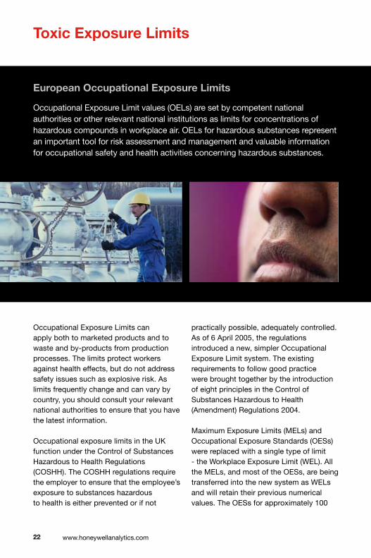
Toxic Exposure Limits
Occupational Exposure Limits can apply both to marketed products and to waste and by-products from production processes. The limits protect workers against health effects, but do not address safety issues such as explosive risk. As limits frequently change and can vary by country, you should consult your relevant national authorities to ensure that you have the latest information.
Occupational exposure limits in the UK function under the Control of Substances Hazardous to Health Regulations (COSHH). The COSHH regulations require the employer to ensure that the employee’s exposure to substances hazardous to health is either prevented or if not
practically possible, adequately controlled. As of 6 April 2005, the regulations introduced a new, simpler Occupational Exposure Limit system. The existing requirements to follow good practice were brought together by the introduction of eight principles in the Control of Substances Hazardous to Health (Amendment) Regulations 2004.
Maximum Exposure Limits (MELs) and Occupational Exposure Standards (OESs) were replaced with a single type of limit - the Workplace Exposure Limit (WEL). All the MELs, and most of the OESs, are being transferred into the new system as WELs and will retain their previous numerical values. The OESs for approximately 100
European Occupational Exposure Limits
Occupational Exposure Limit values (OELs) are set by competent national authorities or other relevant national institutions as limits for concentrations of hazardous compounds in workplace air. OELs for hazardous substances represent an important tool for risk assessment and management and valuable information for occupational safety and health activities concerning hazardous substances.

substances were deleted as the substances are now banned, scarcely used or there is evidence to suggest adverse health effects close to the old limit value. The list of exposure limits is known as EH40 and is available from the UK Health and Safety Executive. All legally enforceable WELs in the UK are air limit values. The maximum admissible or accepted concentration varies from substance to substance according to its toxicity. The exposure times are averaged for eight hours (8-hour TWA) and 15 minutes (short-term exposure limit STEL). For some substances, a brief exposure is considered so critical that they are set only a STEL, which should not be exceeded even for a shorter time. The potency to penetrate through skin is
annotated in the WEL list by remark “Skin”. Carcinogenicity, reproduction toxicity, irritation and sensitisation potential are considered when preparing a proposal for an OEL according to the present scientific knowledge.
��
Period of exposure in minutes
Car
bo
n M
ono
xid
e in
par
ts p
er m
illio
n (p
pm
)
1000
1500
2000
2500
160804020105
500
Effects of exposure to Carbon Monoxide
=Well=Unwell
=Dead!
�� www.honeywellanalytics.com
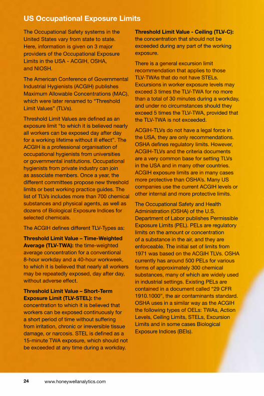
The Occupational Safety systems in the United States vary from state to state. Here, information is given on 3 major providers of the Occupational Exposure Limits in the USA - ACGIH, OSHA, and NIOSH.
The American Conference of Governmental Industrial Hygienists (ACGIH) publishes Maximum Allowable Concentrations (MAC), which were later renamed to “Threshold Limit Values” (TLVs).
Threshold Limit Values are defined as an exposure limit “to which it is believed nearly all workers can be exposed day after day for a working lifetime without ill effect”. The ACGIH is a professional organisation of occupational hygienists from universities or governmental institutions. Occupational hygienists from private industry can join as associate members. Once a year, the different committees propose new threshold limits or best working practice guides. The list of TLVs includes more than 700 chemical substances and physical agents, as well as dozens of Biological Exposure Indices for selected chemicals.
The ACGIH defines different TLV-Types as:
Threshold Limit Value – Time-Weighted Average (TLV-TWA): the time-weighted average concentration for a conventional 8-hour workday and a 40-hour workweek, to which it is believed that nearly all workers may be repeatedly exposed, day after day, without adverse effect.
Threshold Limit Value – Short-Term Exposure Limit (TLV-STEL): the concentration to which it is believed that workers can be exposed continuously for a short period of time without suffering from irritation, chronic or irreversible tissue damage, or narcosis. STEL is defined as a 15-minute TWA exposure, which should not be exceeded at any time during a workday.
Threshold Limit Value - Ceiling (TLV-C): the concentration that should not be exceeded during any part of the working exposure.
There is a general excursion limit recommendation that applies to those TLV-TWAs that do not have STELs. Excursions in worker exposure levels may exceed 3 times the TLV-TWA for no more than a total of 30 minutes during a workday, and under no circumstances should they exceed 5 times the TLV-TWA, provided that the TLV-TWA is not exceeded.
ACGIH-TLVs do not have a legal force in the USA, they are only recommendations. OSHA defines regulatory limits. However, ACGIH-TLVs and the criteria documents are a very common base for setting TLVs in the USA and in many other countries. ACGIH exposure limits are in many cases more protective than OSHA’s. Many US companies use the current ACGIH levels or other internal and more protective limits.
The Occupational Safety and Health Administration (OSHA) of the U.S. Department of Labor publishes Permissible Exposure Limits (PEL). PELs are regulatory limits on the amount or concentration of a substance in the air, and they are enforceable. The initial set of limits from 1971 was based on the ACGIH TLVs. OSHA currently has around 500 PELs for various forms of approximately 300 chemical substances, many of which are widely used in industrial settings. Existing PELs are contained in a document called “29 CFR 1910.1000”, the air contaminants standard. OSHA uses in a similar way as the ACGIH the following types of OELs: TWAs, Action Levels, Ceiling Limits, STELs, Excursion Limits and in some cases Biological Exposure Indices (BEIs).
US Occupational Exposure Limits

��
OccupationalExposureLimitsComparisonTable
The National Institute for Occupational Safety and Health (NIOSH) has the statutory responsibility for recommending exposure levels that are protective to workers. NIOSH has identified Recommended Exposure Levels (RELs) for around 700 hazardous substances. These limits have no legal force. NIOSH recommends their limits via criteria documents to OSHA and other OEL setting institutions. Types of RELs are TWA, STEL, Ceiling and BEIs. The recommendations and the criteria are published in several different document types, such as Current Intelligent Bulletins (CIB), Alerts, Special Hazard Reviews, Occupational Hazard Assessments and Technical Guidelines.
AICGH OSHA NIOSH EH40 Meaning
ThresholdLimit PermissibleExposure Recommended WorkplaceExposure Limitdefinition Values(TLVs) Limits(PELs) ExposureLevels(RELs) Limits(WELs)
TLV-TWA TWA TWA TWA Long-termexposurelimit (8hr-TWAreferenceperiod)
TLV-STEL STEL STEL STEL Short-termexposurelimit (15-minuteexposureperiod)
TLV-C Ceiling Ceiling - Theconcentrationthatshould notbeexceededduringany partoftheworkingexposure
ExcursionLimit ExcursionLimit - - LimitifnoSTELstated
- BEIs BEIs - BiologicalExposureIndicies

�� www.honeywellanalytics.com
Toxic Gases Data
CommonName CASNumber Formula ppm mg.m-3 ppm mg.m-3 ppm mg.m-3 ppm
Ammonia 7664-41-7 NH3 25 18 35 25 50 35 25
Arsine 7784-42-1 AsH3 0.05 0.16 0.05 0.2 0.05
BoronTrichloride 10294-34-5 BCl3
BoronTrifluoride 7637-07-2 BF3 1(ceiling) 3(ceiling) 1(ceiling)
Bromine 7726-95-6 Br2 0.1 0.66 0.3 2 0.1 0.7 0.1
CarbonMonoxide 630-08-0 CO 30 35 200 232 50 55 25
Chlorine 7782-50-5 Cl2 0.5 1.5 1 2.9 1(ceiling) 3(ceiling) 0.5
ChlorineDioxide 10049-04-4 ClO2 0.1 0.28 0.3 0.84 0.1 0.3 0.1
1,4Cyclohexanediisocyanate CHDI
Diborane 19287-45-7 B2H6 0.1 0.1 0.1
Dichlorosilane(DCS) 4109-96-0 H2Cl2Si
DimethylAmine(DMA) 124-40-3 C2H7N 2 3.8 6 11 10 18 5
DimethylHydrazine(UDMH) 57-14-7 C2H8N2 0.01
Disilane 1590-87-0 Si2H6
EthyleneOxide 75-21-8 C2H4O 5 9.2 1 1
Fluorine 7782-41-4 F2 1 1 0.1 0.2 1
Germane 7782-65-2 GeH4 0.2 0.62 0.6 1.9 0.2
HexamethyleneDiisocyanate(HDI) 822-06-0 C8H12N2O2 0.005
Hydrazine 302-01-2 N2H4 0.02 0.03 0.1 0.13 1 1.3 0.01
Hydrogen 1333-74-0 H2 Asphyxiant
HydrogenBromide 10035-10-6 HBr 3 10 3 10 2(ceiling)
HydrogenChloride 7647-01-0 HCl 1 2 5 8 5(ceiling) 7(ceiling) 2(ceiling)
HydrogenCyanide 74-90-8 HCN 10 11 10 11 4.7(ceiling)
HydrogenFluoride 7664-39-3 HF 1.8 1.5 3 2.5 3 3(ceiling)
HydrogenIodide 10034-85-2 HI
HydrogenPeroxide 7722-84-1 H2O2 1 1.4 2 2.8 1 1.4 1
HydrogenSelenide 7783-07-5 H2Se 0.05 0.2 0.05
HydrogenSulphide 7783-06-4 H2S 5 7 10 14 20(ceiling) 10
HydrogenatedMethyleneBisphenylIsocyanate(HMDI)
Isocyanatoethylmethacrylate(IEM) C7H9NO3
IsophoroneDiisocyanate(IPDI) C12H18N2O2 0.005
MethylFluoride(R41) 593-53-3 CH3F
MethyleneBisphenylIsocyanate(MDI) 101-68-8 C15H10N2O2 0.005
MethyleneBisphenylIsocyanate-2(MDI-2) 101-68-8 C15H10N2O2 0.005
MethyleneDianiline(MDA) 101-77-9 C13H14N2 0.01 0.08 0.1
MonomethylHydrazine(MMH) 60-34-4 CH6N2 0.01
NaphthaleneDiisocyanate(NDI) 3173-72-6 C12H6N2O2 0.005
NitricAcid 7697-37-2 HNO3 2 5.2 4 10 2 5 2
ThetoxicgaseslistedbelowcanbedetectedusingequipmentsuppliedbyHoneywellAnalytics.Gasdataissuppliedwhereknown.Asproductdevelopmentisongoing,contactHoneywellAnalyticsifthegasyourequireisnotlisted.Datamaychangebycountryanddate,alwaysrefertolocalup-to-dateregulations.

��
CommonName CASNumber Formula ppm mg.m-3 ppm mg.m-3 ppm mg.m-3 ppm
Ammonia 7664-41-7 NH3 25 18 35 25 50 35 25
Arsine 7784-42-1 AsH3 0.05 0.16 0.05 0.2 0.05
BoronTrichloride 10294-34-5 BCl3
BoronTrifluoride 7637-07-2 BF3 1(ceiling) 3(ceiling) 1(ceiling)
Bromine 7726-95-6 Br2 0.1 0.66 0.3 2 0.1 0.7 0.1
CarbonMonoxide 630-08-0 CO 30 35 200 232 50 55 25
Chlorine 7782-50-5 Cl2 0.5 1.5 1 2.9 1(ceiling) 3(ceiling) 0.5
ChlorineDioxide 10049-04-4 ClO2 0.1 0.28 0.3 0.84 0.1 0.3 0.1
1,4Cyclohexanediisocyanate CHDI
Diborane 19287-45-7 B2H6 0.1 0.1 0.1
Dichlorosilane(DCS) 4109-96-0 H2Cl2Si
DimethylAmine(DMA) 124-40-3 C2H7N 2 3.8 6 11 10 18 5
DimethylHydrazine(UDMH) 57-14-7 C2H8N2 0.01
Disilane 1590-87-0 Si2H6
EthyleneOxide 75-21-8 C2H4O 5 9.2 1 1
Fluorine 7782-41-4 F2 1 1 0.1 0.2 1
Germane 7782-65-2 GeH4 0.2 0.62 0.6 1.9 0.2
HexamethyleneDiisocyanate(HDI) 822-06-0 C8H12N2O2 0.005
Hydrazine 302-01-2 N2H4 0.02 0.03 0.1 0.13 1 1.3 0.01
Hydrogen 1333-74-0 H2 Asphyxiant
HydrogenBromide 10035-10-6 HBr 3 10 3 10 2(ceiling)
HydrogenChloride 7647-01-0 HCl 1 2 5 8 5(ceiling) 7(ceiling) 2(ceiling)
HydrogenCyanide 74-90-8 HCN 10 11 10 11 4.7(ceiling)
HydrogenFluoride 7664-39-3 HF 1.8 1.5 3 2.5 3 3(ceiling)
HydrogenIodide 10034-85-2 HI
HydrogenPeroxide 7722-84-1 H2O2 1 1.4 2 2.8 1 1.4 1
HydrogenSelenide 7783-07-5 H2Se 0.05 0.2 0.05
HydrogenSulphide 7783-06-4 H2S 5 7 10 14 20(ceiling) 10
HydrogenatedMethyleneBisphenylIsocyanate(HMDI)
Isocyanatoethylmethacrylate(IEM) C7H9NO3
IsophoroneDiisocyanate(IPDI) C12H18N2O2 0.005
MethylFluoride(R41) 593-53-3 CH3F
MethyleneBisphenylIsocyanate(MDI) 101-68-8 C15H10N2O2 0.005
MethyleneBisphenylIsocyanate-2(MDI-2) 101-68-8 C15H10N2O2 0.005
MethyleneDianiline(MDA) 101-77-9 C13H14N2 0.01 0.08 0.1
MonomethylHydrazine(MMH) 60-34-4 CH6N2 0.01
NaphthaleneDiisocyanate(NDI) 3173-72-6 C12H6N2O2 0.005
NitricAcid 7697-37-2 HNO3 2 5.2 4 10 2 5 2
EH40WorkplaceExposureLimit(WEL) OSHAPermissibleExposureLimits(PEL)
ACGIHThresholdLimitValue(TLV)
Long-termexposurelimit(8-hourTWAreferenceperiod)
8-hourTWAworkdayanda40-hourworkweek
Short-termexposurelimit(15-minutereferenceperiod)
Long-termexposurelimit(8-hourTWAreferenceperiod)
Ref:EH40/2005Workplaceexposurelimits,OSHAStandard29CFR1910.1000tablesZ-1andZ-2andACGIHThresholdLimitValvesandBiologicalExposureIndicesBook2005.

�� www.honeywellanalytics.com
NitricOxide 10102-43-9 NO 25 30 25
NitrogenDioxide 10102-44-0 NO2 5(ceiling) 9(ceiling) 3
NitrogenTrifluoride 7783-54-2 NF3 10 29 10
n-ButylAmine(N-BA) 109-73-9 C4H11N 5(ceiling) 15(ceiling) 5(ceiling)
Ozone 10028-15-6 O3 0.2 0.4 0.1 0.2 100ppb
Phosgene 75-44-5 COCl2 0.02 0.08 0.06 0.25 0.1 0.4 100ppb
Phosphine 7803-51-2 PH3 0.3 0.42 0.3 0.4 300ppb
PropyleneOxide 75-56-9 C3H6O 5 12 100 240 2
p-PhenyleneDiamine(PPD) 106-50-3 C6H8N2 0.1 0.1 0.1mg/mm3
p-PhenyleneDiisocyanate(PPDI) 104-49-4 C8H4N2O2
Silane 7803-62-5 SiH4 0.5 0.67 1 1.3 5
Stibine 7803-52-3 SbH3 0.1 0.5 0.1
SulphurDioxide 7446-09-5 SO2 5 13 2
SulphuricAcid 7664-93-9 H2SO4 1 0.05
TertiaryButylArsine(TBA) 0.01mg/m3forarsenic
TertiaryButylPhosphine(TBP) 2501-94-2 C4H11P
Tetraethylorthosilicate(TEOS) 78-10-4 C8H20O4Si
Tetrakis(Dimethylamino)Titanium(TDMAT) 3275-24-9 C8H24N4Ti 5asDMA
TetramethylxyleneDiisocyanate(TMXDI) C14H16N2O2
TolueneDiamine(TDA) 95-80-7 C7H10N2 50 191 150 574 lowestfeasible(NIOSH)
TolueneDiisocyanate(TDI) 584-84-9 C9H6N2O2 0.02(ceiling) 0.14(ceiling) 0.005
TriethylAmine(TEA) 121-44-8 C6H15N 2 8 4 17 5
TrimethylhexamethyleneDiisocyanate(TMDI) C11H18N2O2
UnsymetricalDimethylHydrazine(UDMH) 57-14-7 C2H8N2 0.01
XyleneDiisocyanate(XDI)
CommonName CASNumber Formula ppm mg.m-3 ppm mg.m-3 ppm mg.m-3 ppm
Toxic Gases Data (continued)

��
EH40WorkplaceExposureLimit(WEL) OSHAPermissibleExposureLimits(PEL)
ACGIHThresholdLimitValue(TLV)
Long-termexposurelimit(8-hourTWAreferenceperiod)
8-hourTWAworkdayanda40-hourworkweek
Short-termexposurelimit(15-minutereferenceperiod)
Long-termexposurelimit(8-hourTWAreferenceperiod)
NitricOxide 10102-43-9 NO 25 30 25
NitrogenDioxide 10102-44-0 NO2 5(ceiling) 9(ceiling) 3
NitrogenTrifluoride 7783-54-2 NF3 10 29 10
n-ButylAmine(N-BA) 109-73-9 C4H11N 5(ceiling) 15(ceiling) 5(ceiling)
Ozone 10028-15-6 O3 0.2 0.4 0.1 0.2 100ppb
Phosgene 75-44-5 COCl2 0.02 0.08 0.06 0.25 0.1 0.4 100ppb
Phosphine 7803-51-2 PH3 0.3 0.42 0.3 0.4 300ppb
PropyleneOxide 75-56-9 C3H6O 5 12 100 240 2
p-PhenyleneDiamine(PPD) 106-50-3 C6H8N2 0.1 0.1 0.1mg/mm3
p-PhenyleneDiisocyanate(PPDI) 104-49-4 C8H4N2O2
Silane 7803-62-5 SiH4 0.5 0.67 1 1.3 5
Stibine 7803-52-3 SbH3 0.1 0.5 0.1
SulphurDioxide 7446-09-5 SO2 5 13 2
SulphuricAcid 7664-93-9 H2SO4 1 0.05
TertiaryButylArsine(TBA) 0.01mg/m3forarsenic
TertiaryButylPhosphine(TBP) 2501-94-2 C4H11P
Tetraethylorthosilicate(TEOS) 78-10-4 C8H20O4Si
Tetrakis(Dimethylamino)Titanium(TDMAT) 3275-24-9 C8H24N4Ti 5asDMA
TetramethylxyleneDiisocyanate(TMXDI) C14H16N2O2
TolueneDiamine(TDA) 95-80-7 C7H10N2 50 191 150 574 lowestfeasible(NIOSH)
TolueneDiisocyanate(TDI) 584-84-9 C9H6N2O2 0.02(ceiling) 0.14(ceiling) 0.005
TriethylAmine(TEA) 121-44-8 C6H15N 2 8 4 17 5
TrimethylhexamethyleneDiisocyanate(TMDI) C11H18N2O2
UnsymetricalDimethylHydrazine(UDMH) 57-14-7 C2H8N2 0.01
XyleneDiisocyanate(XDI)
CommonName CASNumber Formula ppm mg.m-3 ppm mg.m-3 ppm mg.m-3 ppm
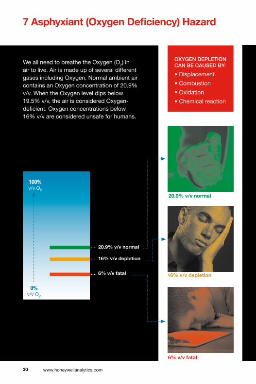
We all need to breathe the Oxygen (O2) in air to live. Air is made up of several different gases including Oxygen. Normal ambient air contains an Oxygen concentration of 20.9% v/v. When the Oxygen level dips below 19.5% v/v, the air is considered Oxygen-deficient. Oxygen concentrations below 16% v/v are considered unsafe for humans.
�0 www.honeywellanalytics.com
7 Asphyxiant (Oxygen Deficiency) Hazard
100%v/v O2
�% v/v fatal
0%v/v O2
1�% v/v depletion
�0.�% v/v normal
�0.�% v/v normal
1�% v/v depletion
oxygen depletion can be caused by:
• Displacement
• Combustion
• Oxidation
• Chemical reaction
�% v/v fatal
�1
� Oxygen Enrichment
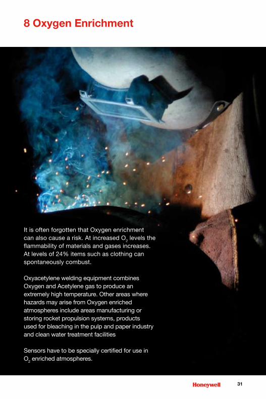
It is often forgotten that Oxygen enrichment can also cause a risk. At increased O2 levels the flammability of materials and gases increases. At levels of 24% items such as clothing can spontaneously combust.
Oxyacetylene welding equipment combines Oxygen and Acetylene gas to produce an extremely high temperature. Other areas where hazards may arise from Oxygen enriched atmospheres include areas manufacturing or storing rocket propulsion systems, products used for bleaching in the pulp and paper industry and clean water treatment facilities
Sensors have to be specially certified for use in O2 enriched atmospheres.
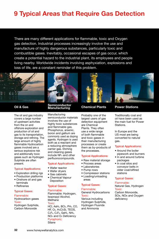
Oil & Gas
The oil and gas industry covers a large number of upstream activities from the on and offshore exploration and production of oil and gas to its transportation, storage and refining. The large amount of highly flammable Hydrocarbon gases involved are a serious explosive risk and additionally toxic gases such as Hydrogen Sulphide are often present.
typical applications:
• Exploration drilling rigs• Production platforms• Onshore oil and gas
terminals• Refineries
typical gases:
Flammable: Hydrocarbon gases Toxic: Hydrogen Sulphide, Carbon Monoxide
Semiconductor Manufacturing
Manufacturing semiconductor materials involves the use of highly toxic substances and flammable gas. Phosphorus, arsenic, boron and gallium are commonly used as doping agents. Hydrogen is used both as a reactant and a reducing atmosphere carrier gas. Etching and cleaning gases include NF3 and other perfluorocompounds.
typical applications:
• Wafer reactor• Wafer dryers• Gas cabinets• Chemical Vapour
Deposition
typical gases:
Flammable: Flammable: Hydrogen, Isopropyl Alcohol, MethaneToxic: HCl, AsH3, BCl3, PH3, CO, HF, O3, H2Cl2Si, TEOS, C4F6, C5F8, GeH4, NH3, NO2 and O2 Deficiency Pyrophoric: Silane
Chemical Plants
Probably one of the largest users of gas detection equipment are Chemical Plants. They often use a wide range of both flammable and toxic gases in their manufacturing processes or create them as by-products of the processes.
typical applications:
• Raw material storage• Process areas• Laboratories• Pump rows• Compressor stations• Loading/unloading
areas
typical gases:
Flammable: General Hydrocarbons Toxic: Various including Hydrogen Sulphide, Hydrogen Fluoride and Ammonia
Power Stations
Traditionally coal and oil have been used as the main fuel for Power Stations. In Europe and the US most are being converted to natural gas.
typical applications:
• Around the boiler pipework and burners
• In and around turbine packages
• In coal silos and conveyor belts in older coal/oilfired stations
typical gases:
Flammable: Natural Gas, HydrogenToxic: Carbon Monoxide, SOx, NOx and Oxygen deficiency
�� www.honeywellanalytics.com
There are many different applications for flammable, toxic and Oxygen gas detection. Industrial processes increasingly involve the use and manufacture of highly dangerous substances, particularly toxic and combustible gases. Inevitably, occasional escapes of gas occur, which create a potential hazard to the industrial plant, its employees and people living nearby. Worldwide incidents involving asphyxiation, explosions and loss of life, are a constant reminder of this problem.
� Typical Areas that Require Gas Detection

Waste Water Treatment Plants
Waste Water Treatment Plants are a familiar site around many cities and towns.
Sewage naturally gives off both Methane and H2S. The ‘rotten eggs’ smell of H2S can often be noticed as the nose can detect it at less than 0.1ppm.
typical applications:
• Digesters• Plant sumps• H2S scrubbers• Pumps
typical gases:
Flammable: Methane, Solvent vapoursToxic: Hydrogen Sulphide, Carbon Dioxide, Chlorine, Sulphur Dioxide, Ozone
Boiler Rooms
Boiler Rooms come in all shapes and sizes. Small buildings may have a single boiler whereas larger buildings often have large boiler rooms housing several large boilers.
typical applications:
• Flammable gas leaks from the incoming gas main
• Leaks from the boiler and surrounding gas piping
• Carbon Monoxide given off badly maintained boiler
typical gases:
Flammable: MethaneToxic: Carbon Monoxide
Hospitals
Hospitals may use many different flammable and toxic substances, particularly in their laboratories. Additionally, many are very large and have onsite utility supplies and back up power stations.
typical applications:
• Laboratories• Refrigeration plants• Boiler rooms
typical gases:
Flammable: Methane, HydrogenToxic: Carbon Monoxide, Chlorine, Ammonia, Ethylene Oxide and Oxygen deficiency
Tunnels/Car Parks
Car Tunnels and enclosed Car Parks need to be monitored for the toxic gases from exhaust fumes. Modern tunnels and car parks use this monitoring to control the ventilation fans. Tunnels may also need to be monitored for the buildup of natural gas.
typical applications:
• Car tunnels• Underground and
enclosed car parks• Access tunnels• Ventilation control
typical gases:
Flammable: Methane (natural gas), LPG, LNG, Petrol VapourToxic: Carbon Monoxide, Nitrogen Dioxide
��
In most industries, one of the key parts of the safety plan for reducing the risks to personnel and plant is the use of early warning devices such as gas detectors. These can help to provide more time in which to take remedial or protective action. They can also be used as part of a total integrated monitoring and safety system for an industrial plant.

Combustible gas sensors
Many people have probably seen a flame safety lamp at some time and know something about its use as an early form of ‘firedamp’ gas detector in underground coal mines and sewers. Although originally intended as a source of light, the device could also be used to estimate the level of combustible gases- to an accuracy of about 25-50%, depending on the user’s experience, training, age, colour perception etc. Modern combustible gas detectors have to be much more accurate, reliable and repeatable than this and although various attempts were made to overcome the safety lamp’s subjectiveness of measurement (by using a flame temperature sensor for instance), it has now been almost entirely superseded by more modern, electronic devices.
Nevertheless, today’s most commonly used device, the catalytic detector, is in some respects a modern development of the early flame safety lamp, since it also relies for its operation on the combustion of a gas and its conversion to Carbon Dioxide and water.
Catalytic sensor
Nearly all modern, low-cost, combustible gas detection sensors are of the electro-catalytic type. They consist of a very small sensing element sometimes called a ‘bead’, a ‘Pellistor’, or a ‘Siegistor’- the last two being registered trade names for commercial devices. They are made of an electrically heated platinum wire coil, covered first with a ceramic base such as alumina and then with a final outer coating of palladium or rhodium catalyst dispersed in a substrate of thoria.
This type of sensor operates on the principle that when a combustible gas/air mixture passes over the hot catalyst surface, combustion occurs and the heat evolved increases the temperature of the ‘bead’. This in turn alters the resistance of the platinum coil and can be measured by using the coil as a temperature thermometer in a standard electrical bridge circuit. The resistance change is then directly related to the gas concentration in the surrounding atmosphere and can be displayed on a meter or some similar indicating device.
�� www.honeywellanalytics.com
10 Principles of Detection
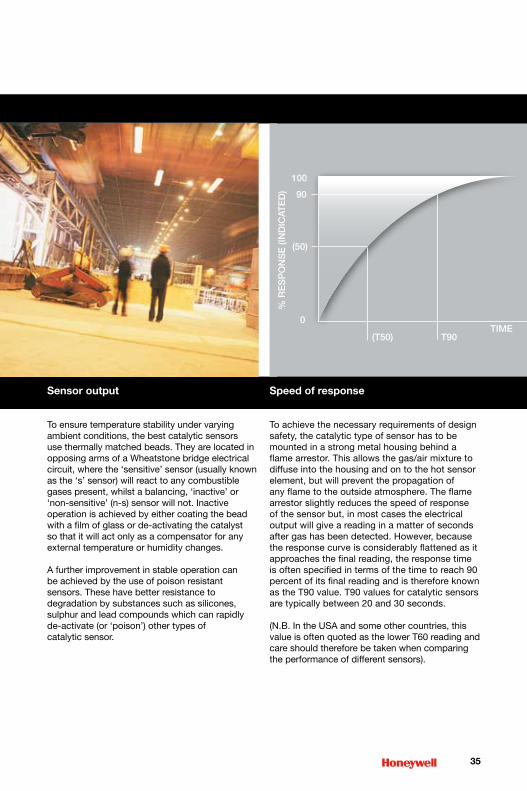
Sensor output
To ensure temperature stability under varying ambient conditions, the best catalytic sensors use thermally matched beads. They are located in opposing arms of a Wheatstone bridge electrical circuit, where the ‘sensitive’ sensor (usually known as the ‘s’ sensor) will react to any combustible gases present, whilst a balancing, ‘inactive’ or ‘non-sensitive’ (n-s) sensor will not. Inactive operation is achieved by either coating the bead with a film of glass or de-activating the catalyst so that it will act only as a compensator for any external temperature or humidity changes.
A further improvement in stable operation can be achieved by the use of poison resistant sensors. These have better resistance to degradation by substances such as silicones, sulphur and lead compounds which can rapidly de-activate (or ‘poison’) other types of catalytic sensor.
Speed of response
To achieve the necessary requirements of design safety, the catalytic type of sensor has to be mounted in a strong metal housing behind a flame arrestor. This allows the gas/air mixture to diffuse into the housing and on to the hot sensor element, but will prevent the propagation of any flame to the outside atmosphere. The flame arrestor slightly reduces the speed of response of the sensor but, in most cases the electrical output will give a reading in a matter of seconds after gas has been detected. However, because the response curve is considerably flattened as it approaches the final reading, the response time is often specified in terms of the time to reach 90 percent of its final reading and is therefore known as the T90 value. T90 values for catalytic sensors are typically between 20 and 30 seconds.
(N.B. In the USA and some other countries, this value is often quoted as the lower T60 reading and care should therefore be taken when comparing the performance of different sensors).
��
100
90
0
(50)
(t50) t90
% R
es
po
ns
e (i
nd
icat
ed
)
time

Calibration
The most common failure in catalytic sensors is performance degradation caused by exposure to certain poisons’. It is therefore essential that any gas monitoring system should not only be calibrated at the time of installation, but also checked regularly and re-calibrated as necessary. Checks must be made using an accurately calibrated standard gas mixture so that the zero and ‘span’ levels can be set correctly on the controller.
Codes of practice such as EN50073:1999 can provide some guidance about the calibration checking frequency and the alarm level settings. Typically, checks should initially be made at weekly intervals but the periods can be extended as operational experience is gained. Where two alarm levels are required, these are normally set at 20-25% LEL for the lower level and 50-55% LEL for the upper level.
Older (and lower cost) systems require two people to check and calibrate, one to expose the sensor to a flow of gas and the other to check the reading shown on the scale of its control unit. Adjustments are then made at the controller to the zero and span potentiometers until the reading exactly matches that of the gas mixture concentration.
Remember that where adjustments have to be made within a flameproof enclosure, the power must first be disconnected and a permit obtained to open the enclosure.
Today, there are a number of ‘one-man’ calibration systems available which allow the calibration procedures to be carried out at the sensor itself. This considerably reduces the time and cost of maintenance, particularly where the sensors are in difficult to get to locations, such as an offshore oil or gas platform. Alternatively, there are now some sensors available which are designed to intrinsically safe standards, and with these it is possible to calibrate the sensors at a convenient place away from the site (in a maintenance depot for instance). Because they are intrinsically safe, it is allowed to freely exchange them with the sensors needing replacement on site, without first shutting down the system for safety.
Maintenance can therefore be carried out on a ‘hot’ system and is very much faster and cheaper than early, conventional systems.
�� www.honeywellanalytics.com
Sensor screwed to Junction Box – two-man
calibration
Sensor screwed to Transmitter with intrusive
one-man calibration
Sensor screwed to Transmitter with non
intrusive one-man calibration
Transmitter with remote sensor – one-man non intrusive calibration
typical types of gas sensoR/tRansmitteR
Principles of Detection (continued)
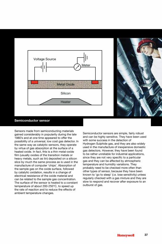
Semiconductor sensor
Sensors made from semiconducting materials gained considerably in popularity during the late 1980’s and at one time appeared to offer the possibility of a universal, low cost gas detector. In the same way as catalytic sensors, they operate by virtue of gas absorption at the surface of a heated oxide. In fact, this is a thin metal-oxide film (usually oxides of the transition metals or heavy metals, such as tin) deposited on a silicon slice by much the same process as is used in the manufacture of computer ‘chips’. Absorption of the sample gas on the oxide surface, followed by catalytic oxidation, results in a change of electrical resistance of the oxide material and can be related to the sample gas concentration. The surface of the sensor is heated to a constant temperature of about 200-250°C, to speed up the rate of reaction and to reduce the effects of ambient temperature changes.
Semiconductor sensors are simple, fairly robust and can be highly sensitive. They have been used with some success in the detection of Hydrogen Sulphide gas, and they are also widely used in the manufacture of inexpensive domestic gas detectors. However, they have been found to be rather unreliable for industrial applications, since they are not very specific to a particular gas and they can be affected by atmospheric temperature and humidity variations. They probably need to be checked more often than other types of sensor, because they have been known to ‘go to sleep’ (i.e. lose sensitivity) unless regularly checked with a gas mixture and they are slow to respond and recover after exposure to an outburst of gas.
��
HeaterHeater
Metal Oxide
Voltage Source
Meter
Silicon
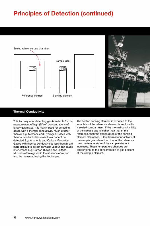
Principles of Detection (continued)
Thermal Conductivity
This technique for detecting gas is suitable for the measurement of high (%V/V) concentrations of binary gas mixes. It is mainly used for detecting gases with a thermal conductivity much greater than air e.g. Methane and Hydrogen. Gases with thermal conductivities close to air cannot be detected E.g. Ammonia and Carbon Monoxide. Gases with thermal conductivities less than air are more difficult to detect as water vapour can cause interference E.g. Carbon Dioxide and Butane. Mixtures of two gases in the absence of air can also be measured using this technique.
The heated sensing element is exposed to the sample and the reference element is enclosed in a sealed compartment. If the thermal conductivity of the sample gas is higher than that of the reference, then the temperature of the sensing element decreases. If the thermal conductivity of the sample gas is less than that of the reference then the temperature of the sample element increases. These temperature changes are proportional to the concentration of gas present at the sample element.
�� www.honeywellanalytics.com
Sealed reference gas chamber
Sample gas
Reference element Sensing element
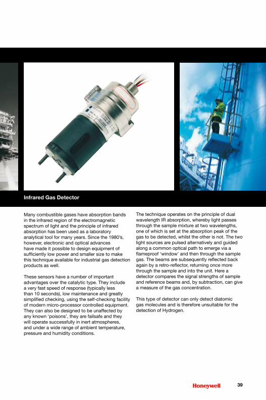
Infrared Gas Detector
Many combustible gases have absorption bands in the infrared region of the electromagnetic spectrum of light and the principle of infrared absorption has been used as a laboratory analytical tool for many years. Since the 1980’s, however, electronic and optical advances have made it possible to design equipment of sufficiently low power and smaller size to make this technique available for industrial gas detection products as well.
These sensors have a number of important advantages over the catalytic type. They include a very fast speed of response (typically less than 10 seconds), low maintenance and greatly simplified checking, using the self-checking facility of modern micro-processor controlled equipment. They can also be designed to be unaffected by any known ‘poisons’, they are failsafe and they will operate successfully in inert atmospheres, and under a wide range of ambient temperature, pressure and humidity conditions.
The technique operates on the principle of dual wavelength IR absorption, whereby light passes through the sample mixture at two wavelengths, one of which is set at the absorption peak of the gas to be detected, whilst the other is not. The two light sources are pulsed alternatively and guided along a common optical path to emerge via a flameproof ‘window’ and then through the sample gas. The beams are subsequently reflected back again by a retro-reflector, returning once more through the sample and into the unit. Here a detector compares the signal strengths of sample and reference beams and, by subtraction, can give a measure of the gas concentration.
This type of detector can only detect diatomic gas molecules and is therefore unsuitable for the detection of Hydrogen.
��
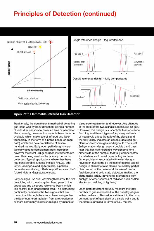
Open Path Flammable Infrared Gas Detector
�0 www.honeywellanalytics.com
Principles of Detection (continued)
Traditionally, the conventional method of detecting gas leaks was by point detection, using a number of individual sensors to cover an area or perimeter. More recently, however, instruments have become available which make use of infrared and laser technology in the form of a broad beam (or open path) which can cover a distance of several hundred metres. Early open path designs were typically used to complement point detection, however the latest 3rd generation instruments are now often being used as the primary method of detection. Typical applications where they have had considerable success include FPSOs, add jettys, loading/unloading terminals, pipelines, perimeter monitoring, off-shore platforms and LNG (Liquid Natural Gas) storage areas.
Early designs use dual wavelength beams, the first coinciding with the absorption band peak of the target gas and a second reference beam which lies nearby in an unabsorbed area. The instrument continually compares the two signals that are transmitted through the atmosphere, using either the back-scattered radiation from a retroreflector or more commonly in newer designs by means of
a separate transmitter and receiver. Any changes in the ratio of the two signals is measured as gas. However, this design is susceptible to interference from fog as different types of fog can positively or negatively affect the ratio of the signals and thereby falsely indicate an upscale gas reading/alarm or downscale gas reading/fault. The latest 3rd generation design uses a double band pass filter that has two reference wavelengths (one either side of the sample) that fully compensates for interference from all types of fog and rain. Other problems associated with older designs have been overcome by the use of coaxial optical design to eliminate false alarms caused by partial obscuration of the beam and the use of xenon flash lamps and solid state detectors making the instruments totally immune to interference from sunlight or other sources of radiation such as flare stacks, arc welding or lightning.
Open path detectors actually measure the total number of gas molecules (i.e. the quantity of gas) within the beam. This value is different to the usual concentration of gas given at a single point and is therefore expressed in terms of LEL meters.
R S R R S R R S R R S R
Fogtype1
R S R R S R R S R R S R
Fogtype2
S R S R R S R
Fogtype1 Fogtype2
Downscalegas/fault
Upscalegas/falsealarm
Single reference design – fog interference
Double reference design – fully compensates
Infrared intensity
Det
ecto
r o
utp
ut
FILAMENTLAMP
SUNLIGHT
XENONDISCHARGELIGHT
InfraredIntensity
Dete
ctor
out
put
Solidstatedetectors
Oldersystemleadsaltdetectors
MaximumIntensityof:
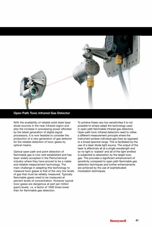
Open Path Toxic Infrared Gas Detector
�1
With the availability of reliable solid state laser diode sources in the near infrared region and also the increase in processing power afforded by the latest generation of digital signal processors, it is now feasible to consider the production of a new generation of gas detector for the reliable detection of toxic gases by optical means.
Optical open path and point detection of flammable gas is now well established and has been widely accepted in the Petrochemical industry where they have proved to be a viable and reliable measurement technology. The main challenge in adapting this technology to measure toxic gases is that of the very low levels of gas that must be reliably measured. Typically flammable gases need to be measured at percent levels of concentration. However typical toxic gases are dangerous at part per million (ppm) levels, i.e. a factor of 1000 times lower than for flammable gas detection.
To achieve these very low sensitivities it is not possible to simply adapt the technology used in open path flammable infrared gas detectors. Open path toxic infrared detectors need to utilise a different measurement principle where the instrument probes individual gas lines as opposed to a broad spectral range. This is facilitated by the use of a laser diode light source. The output of the laser is effectively all at a single wavelength and so no light is ‘wasted’ and all of the light emitted is subjected to absorption by the target toxic gas. This provides a significant enhancement of sensitivity compared to open path flammable gas detection techniques and further enhancements are achieved by the use of sophisticated modulation techniques.

Gas specific electrochemical sensors can be used to detect the majority of common toxic gases, including CO, H2S, Cl2, SO2 etc. in a wide variety of safety applications.Electrochemical sensors are compact, require very little power, exhibit excellent linearity and repeatability and generally have a long life span, typically one to three years. Response times, denoted as T90, i.e. time to reach 90% of the final response, are typically 30-60 seconds and minimum detection limits range from 0.02 to 50ppm depending upon target gas type.
Electrochemical Sensor
Commercial designs of electrochemical cell are numerous but share many of the common features described below:
Three active gas diffusion electrodes are immersed in a common electrolyte, frequently a concentrated aqueous acid or salt solution, for efficient conduction of ions between the working and counter electrodes.
Depending on the specific cell the target gas is either oxidised or reduced at the surface of the working electrode. This reaction alters the potential of the working electrode relative to the reference electrode. The primary function of the associated electronic driver circuit connected to the cell is to minimise this potential difference by passing current between the working and counter electrodes, the measured current being proportional to the target gas concentration. Gas enters the cell through an external diffusion barrier that is porous to gas but impermeable to liquid.
Many designs incorporate a capillary diffusion barrier to limit the amount of gas contacting the working electrode and thereby maintaining “amperometric” cell operation.
A minimum concentration of Oxygen is required for correct operation of all electrochemical cells, making them unsuitable for certain process monitoring applications. Although the electrolyte contains a certain amount of dissolved Oxygen, enabling short-term detection (minutes) of the target gas in an Oxygen-free environment, it is strongly advised that all calibration gas streams incorporate air as the major component or diluent.
Specificity to the target gas is achieved either by optimisation of the electrochemistry, i.e. choice of catalyst and electrolyte, or else by incorporating filters within the cell which physically absorb or chemically react with certain interferent gas molecules
in order to increase target gas specificity. It is important that the appropriate product manual be consulted to understand the effects of potential interferent gases on the cell response.
The necessary inclusion of aqueous electrolytes within electrochemical cells results in a product that is sensitive to environmental conditions of both temperature and humidity. To address this, the patented Surecell™ design incorporates two electrolyte reservoirs that allows for the ‘take up’ and ‘loss’ of electrolyte that occurs in high temperature/high humidity and low temperature/low humidity environments.
Electrochemical sensor life is typically warranted for 2 years, but the actual lifetime frequently exceeds the quoted values. The exceptions to this are Oxygen, Ammonia and Hydrogen Cyanide sensors where components of the cell are necessarily consumed as part of the sensing reaction mechanism.
�� www.honeywellanalytics.com
Housing
Carbon Filter
Working Electrode
2nd expansionreservoir
Counter Electrode
1st small electrolyte
reservoir
Output Pins
Patented Surecell™ Two Reservoir Design
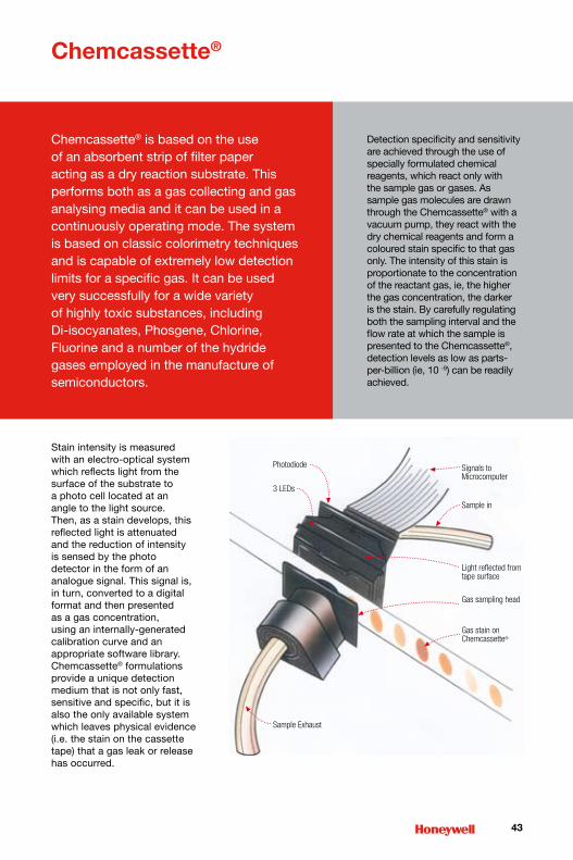
Photodiode
3 LEDs
Sample Exhaust
Gas stain on Chemcassette®
Gas sampling head
Light reflected from tape surface
Sample in
Signals to Microcomputer
Chemcassette®
Chemcassette® is based on the use of an absorbent strip of filter paper acting as a dry reaction substrate. This performs both as a gas collecting and gas analysing media and it can be used in a continuously operating mode. The system is based on classic colorimetry techniques and is capable of extremely low detection limits for a specific gas. It can be used very successfully for a wide variety of highly toxic substances, including Di-isocyanates, Phosgene, Chlorine, Fluorine and a number of the hydride gases employed in the manufacture of semiconductors.
��
Detection specificity and sensitivity are achieved through the use of specially formulated chemical reagents, which react only with the sample gas or gases. As sample gas molecules are drawn through the Chemcassette® with a vacuum pump, they react with the dry chemical reagents and form a coloured stain specific to that gas only. The intensity of this stain is proportionate to the concentration of the reactant gas, ie, the higher the gas concentration, the darker is the stain. By carefully regulating both the sampling interval and the flow rate at which the sample is presented to the Chemcassette®, detection levels as low as parts-per-billion (ie, 10 -9) can be readily achieved.
Stain intensity is measured with an electro-optical system which reflects light from the surface of the substrate to a photo cell located at an angle to the light source. Then, as a stain develops, this reflected light is attenuated and the reduction of intensity is sensed by the photo detector in the form of an analogue signal. This signal is, in turn, converted to a digital format and then presented as a gas concentration, using an internally-generated calibration curve and an appropriate software library. Chemcassette® formulations provide a unique detection medium that is not only fast, sensitive and specific, but it is also the only available system which leaves physical evidence (i.e. the stain on the cassette tape) that a gas leak or release has occurred.
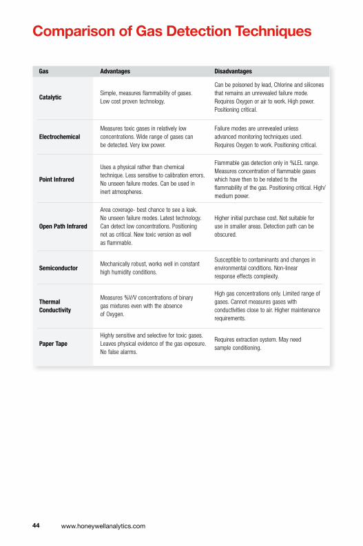
�� www.honeywellanalytics.com
Comparison of Gas Detection Techniques
Gas Advantages Disadvantages
CatalyticSimple,measuresflammabilityofgases.Lowcostproventechnology.
Canbepoisonedbylead,Chlorineandsiliconesthatremainsanunrevealedfailuremode.RequiresOxygenorairtowork.Highpower.Positioningcritical.
ElectrochemicalMeasurestoxicgasesinrelativelylowconcentrations.Widerangeofgasescanbedetected.Verylowpower.
Failuremodesareunrevealedunlessadvancedmonitoringtechniquesused.RequiresOxygentowork.Positioningcritical.
PointInfrared
Usesaphysicalratherthanchemicaltechnique.Lesssensitivetocalibrationerrors.Nounseenfailuremodes.Canbeusedininertatmospheres.
Flammablegasdetectiononlyin%LELrange.Measuresconcentrationofflammablegaseswhichhavethentoberelatedtotheflammabilityofthegas.Positioningcritical.High/mediumpower.
OpenPathInfrared
Areacoverage-bestchancetoseealeak.Nounseenfailuremodes.Latesttechnology.Candetectlowconcentrations.Positioningnotascritical.Newtoxicversionaswellasflammable.
Higherinitialpurchasecost.Notsuitableforuseinsmallerareas.Detectionpathcanbeobscured.
SemiconductorMechanicallyrobust,workswellinconstanthighhumidityconditions.
Susceptibletocontaminantsandchangesinenvironmentalconditions.Non-linearresponseeffectscomplexity.
ThermalConductivity
Measures%V/VconcentrationsofbinarygasmixturesevenwiththeabsenceofOxygen.
Highgasconcentrationsonly.Limitedrangeofgases.Cannotmeasuresgaseswithconductivitiesclosetoair.Highermaintenancerequirements.
PaperTapeHighlysensitiveandselectivefortoxicgases.Leavesphysicalevidenceofthegasexposure.Nofalsealarms.
Requiresextractionsystem.Mayneedsampleconditioning.

��
Comparison of Gas Detection Techniques 11 Portable Gas Detectors
Flammable and toxic gas detection instruments are generally available in two different formats: portable, i.e. ‘spot reading’ detectors and ‘fixed’, permanently sited monitors. Which of these types is most appropriate for a particular application will depend on several factors, including how often the area is accessed by personnel, site conditions, whether the hazard is permanent or transitory, how often testing is needed, and last but not least, the availability of finances.
Portable instruments probably account for nearly half of the total of all modern, electronic gas detectors in use today. In most countries, legislation also requires their use by anyone working in confined spaces such as sewers and underground telephone and electricity ducts. Generally, portable gas detectors are compact, robust, waterproof and lightweight and can be easily carried or attached to clothing. They are also useful for locating the exact point of a leak which was first detected with a fixed detection system.
Portable gas detectors are available as single or multi-gas units. The single gas units contain one sensor for the detection of a specific gas while multi-gas units usually contain up to four different gas sensors (typically Oxygen, flammable, Carbon Monoxide and Hydrogen Sulphide). Products range from simple alarm only disposable units to advanced fully configurable and serviceable instruments with features such as datalogging, internal pump sampling, auto calibration routines and connectivity to other units.
Recent portable gas detector design advances include the use of more robust and lightweight materials for their construction. The use of high power microprocessors enables data processing for instrument self-checking, running operating software, data storage, and auto calibration routines. Modular designs allow simple routine servicing and maintenance. New battery technology has provided extended operating time between charges in a smaller and more lightweight package.
Future designs are likely to see the integration of other technologies such as GPS, bluetooth and voice communication as well as the incorporation of gas detection into other safety equipment.

The North American system for the certification, installation, and inspection of hazardous locations equipment includes the following elements:
• Installation Codes – E.g. NEC, CEC
• Standard Developing Organisations (SDOs) – E.g. UL, CSA, FM
• Nationally Recognised Testing Laboratories (NRTLs) – Third Party Certifiers e.g. ARL, CSA, ETI, FM, ITSNA, MET, UL
• Inspection Authorities – E.g. OSHA, IAEI, USCG
The installation codes in North America are the NEC (National Electric Code) for the USA, and the CEC (Canadian Electric Code) for Canada. In both countries these guides are accepted and used by most authorities as the final standard on installation and use of electrical products. Details include equipment construction, performance and installation requirements, and area classification requirements. With the issuance of the new NEC these are now almost identical.
The Standards Developing Organisations (SDOs) work with industry to develop the appropriate overall equipment requirements. Certain SDOs also serve as members of the technical committees charged with the development and maintenance of the North American installation codes for hazardous locations.
The Nationally Recognised Testing Laboratories (NRTLs) are independent third-party certifiers who assess the conformity of equipment with these requirements. The equipment tested and approved by these agencies is then suitable for use under the NEC or CEC installation standards.
In the United States of America the inspection authority responsible is OSHA (Occupational Health and Safety Administration). In Canada the inspection authority is the Standards Council of Canada. To confirm compliance to all national standards both countries require an additional indication on products tested and approved. As an example CSA approved product to USA standards must add NRTL/C to the CSA symbol. In Canada, UL must add a small c to its label to indicate compliance to all Canadian standards.
�� www.honeywellanalytics.com
1� North American Hazardous Area Standards and Approvals
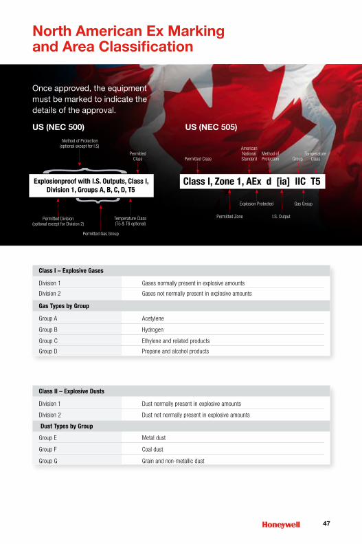
��
North American Ex Marking and Area Classification
ClassI–ExplosiveGases
Division1 Gasesnormallypresentinexplosiveamounts
Division2 Gasesnotnormallypresentinexplosiveamounts
GasTypesbyGroup
GroupA Acetylene
GroupB Hydrogen
GroupC Ethyleneandrelatedproducts
GroupD Propaneandalcoholproducts
ClassII–ExplosiveDusts
Division1 Dustnormallypresentinexplosiveamounts
Division2 Dustnotnormallypresentinexplosiveamounts
DustTypesbyGroup
GroupE Metaldust
GroupF Coaldust
GroupG Grainandnon-metallicdust
US (NEC �00) US (NEC �0�)
Once approved, the equipment must be marked to indicate the details of the approval.

All countries within the EC also have governing bodies that set additional standards for products and wiring methods. Each member country of the EC has either government or third party laboratories that test and approve products to IEC and or CENELEC standards. Wiring methods change even under
CENELEC this is primarily as to the use of cable, armoured cable, and type of armoured cable or conduit. Standards can change within a country depending on the location or who built a facility. Certified apparatus carries the ‘EEx’ mark.
�� www.honeywellanalytics.com
Approved National Test Houses which are cited in the EC Directives may use the EC Distinctive Community Mark: Note: This is not a
Certification Mark
1� European and Rest of World Hazardous Area Standards and Approvals
The standards used in most countries outside of North America are IEC / CENELEC. The IEC (International Electrotechnical Commission) has set broad standards for equipment and classification of areas. CENELEC (European Committee for Electrotechnical Standardisation) is a rationalising group that uses IEC standards as a base and harmonises them with all member countries standards. The CENELEC mark is accepted in all European Community (EC) countries.

��
Approved National Test Houses which are cited in the EC Directives may use the EC Distinctive Community Mark: Note: This is not a
Certification Mark
cenelec membeR countRies:
AustriaBelgiumCyprusCzech Republic
DenmarkEstoniaFinland FranceGermanyGreeceHungaryIceland
IrelandItalyLatviaLithuaniaLuxembourgMaltaNetherlandsNorway
Poland PortugalSlovakiaSlovenia SpainSwedenSwitzerlandUnited Kingdom
Key
CenelecMembersCenelecAffiliates

ATEX = ATmospheres EXplosibles
There are two European Directives that have been law since July 2003 that detail the manufacturers and users obligations regarding the design and use of apparatus in hazardous atmospheres.
The ATEX directives set the MINIMUM standards for both the employer and Manufacturer regarding explosive atmospheres. It is the responsibility of the employer to conduct an assessment of explosive risk and to take necessary measures to eliminate or reduce the risk.
atex diRective 94/9/ec aRticle 100a
Article 100a describes the manufacturers responsibilities:
• The requirements of equipment and protective systems intended for use in potentially explosive atmospheres (e.g. Gas Detectors)
• The requirements of safety and controlling devices intended for use outside of potentially explosive atmospheres but required for the safe functioning of equipment and protective systems (e.g. Controllers)
• The Classification of Equipment Groups into Categories
• The Essential Health and Safety Requirements (EHSRs). Relating to the design and construction of the equipment / systems
In order to comply with the ATEX directive the equipment must:
• display a CE mark
• have the necessary hazardous area certification
• meet a recognised performance standard e.g. EN 61779-1:2000 for flammable gas detectors
�0 www.honeywellanalytics.com
1� ATEX
Responsibility Directive Article
Manufacturer 94/9/EC 100a
Employer(EndUser) 1992/92/EC 137

�1
EN50014Series Definition ATEX
Zone0 Areasinwhichexplosiveatmospheres Category1 causedbymixturesofairandgases, vapours,mistsordustsarepresent continuouslyorforlongperiodsoftime
Zone1 Areasinwhichexplosiveatmospheres Category2causedbymixturesofairandgases,vapours,mistsordustsarelikelytooccur
Zone2 Areasinwhichexplosiveatmospheres Category3causedbymixturesofairorgases,vapours,mistsordustsarelikelytooccuroronlyoccurinfrequentlyorforshortperiodsoftime
ATEXCategory PermittedCertificationType
Category1 EExia
Category2 EExib,EExd,EExe,EExp,EExm,EExo,EExq
Category3 EExib,EExd,EExe,EExp,EExm,EExo,EExq,EExn
The classification of hazardous areas has been re-defined in the ATEX directive

�� www.honeywellanalytics.com
Equipment Markings
CENELEC / IEC
E Ex d IIC T5 (Tamb -40˚C to +55˚C)
Complies with:E = EN 50014A = NEC 505
EU Explosionprotected
(Ex) symbol
Type ofprotection
EU Explosive atmosphere symbol
Equipment groupI : MiningII : other areas (Ex)
Equipment categoryGas1 : Zone 02 : Zone 13 : Zone 2
Type of explosive atmosphereG : Gas, mist, vaporD : Dust
Dust1 : Zone 202 : Zone 213 : Zone 22
MiningM1 : energisedM2 : de-energised
Temperature Class (Group II)
Apparatusgroup
Referenced to ambient –20˚C to +40˚C unless indicated as above
0999
CE Mark Notified bodynumber
II 2 G Assessment of Explosion RisksThe employer must conduct a risk assessment including:
1. Probability of explosive atmosphere Zone Area classification
�. Probability of ignition source Equipment Categories
3. Nature of flammable materials Gas groups, ignition temperature (T rating),
gas, vapour, mists and dusts
�. Scale of effect of explosion Personnel, plant, environment
atex diRective 1992/92/ec aRticle 137
Article 137 describes the responsibilities of the employer. New plant must comply from July 2003. Existing plants must comply from July 2006. In the UK, this directive (also known as the ‘Use’ Directive) is implemented by the Health and Safety Executive (HSE) as The Dangerous Substances and Explosive Atmospheres Regulations 2002 (DSEAR).
It sets out to:
Control
theeffectsofexplosions
Avoid
theignitionofexplosiveatmospheres
Prevent
theformationofexplosiveatmospheres
ifnot ifnot
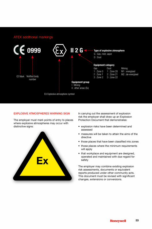
explosive atmospheRes WaRning sign
The employer must mark points of entry to places where explosive atmospheres may occur with distinctive signs:
In carrying out the assessment of explosion risk the employer shall draw up an Explosion Protection Document that demonstrates:
• explosion risks have been determined and assessed
• measures will be taken to attain the aims of the directive
• those places that have been classified into zones
• those places where the minimum requirements will apply
• that workplace and equipment are designed, operated and maintained with due regard for safety
The employer may combine existing explosion risk assessments, documents or equivalent reports produced under other community acts. This document must be revised with significant changes, extensions or conversions.
��
ATEX additional markings
E Ex d IIC T5 (Tamb -40˚C to +55˚C)
Complies with:E = EN 50014A = NEC 505
EU Explosionprotected
(Ex) symbol
Type ofprotection
EU Explosive atmosphere symbol
Equipment groupI : MiningII : other areas (Ex)
Equipment categoryGas1 : Zone 02 : Zone 13 : Zone 2
Type of explosive atmosphereG : Gas, mist, vaporD : Dust
Dust1 : Zone 202 : Zone 213 : Zone 22
MiningM1 : energisedM2 : de-energised
Temperature Class (Group II)
Apparatusgroup
Referenced to ambient –20˚C to +40˚C unless indicated as above
0999
CE Mark Notified bodynumber
II 2 GE Ex d IIC T5 (Tamb -40˚C to +55˚C)
Complies with:E = EN 50014A = NEC 505
EU Explosionprotected
(Ex) symbol
Type ofprotection
EU Explosive atmosphere symbol
Equipment groupI : MiningII : other areas (Ex)
Equipment categoryGas1 : Zone 02 : Zone 13 : Zone 2
Type of explosive atmosphereG : Gas, mist, vaporD : Dust
Dust1 : Zone 202 : Zone 213 : Zone 22
MiningM1 : energisedM2 : de-energised
Temperature Class (Group II)
Apparatusgroup
Referenced to ambient –20˚C to +40˚C unless indicated as above
0999
CE Mark Notified bodynumber
II 2 G
Ex
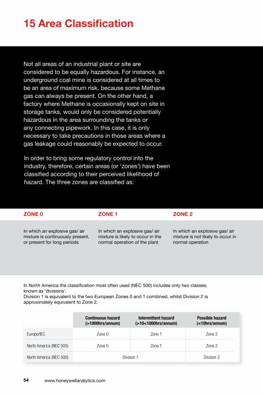
15 Area Classification
In order to bring some regulatory control into the industry, therefore, certain areas (or ‘zones’) have been classified according to their perceived likelihood of hazard. The three zones are classified as:
�� www.honeywellanalytics.com
Not all areas of an industrial plant or site are considered to be equally hazardous. For instance, an underground coal mine is considered at all times to be an area of maximum risk, because some Methane gas can always be present. On the other hand, a factory where Methane is occasionally kept on site in storage tanks, would only be considered potentially hazardous in the area surrounding the tanks or any connecting pipework. In this case, it is only necessary to take precautions in those areas where a gas leakage could reasonably be expected to occur.
ZONE 0
In which an explosive gas/ air mixture is continuously present, or present for long periods
ZONE 1
In which an explosive gas/ air mixture is likely to occur in the normal operation of the plant
ZONE �
In which an explosive gas/ air mixture is not likely to occur in normal operation
In North America the classification most often used (NEC 500) includes only two classes, known as ‘divisions’. Division 1 is equivalent to the two European Zones 0 and 1 combined, whilst Division 2 is approximately equivalent to Zone 2.
Continuoushazard(>1000hrs/annum)
Intermittenthazard(>10<1000hrs/annum)
Possiblehazard(<10hrs/annum)
Europe/IEC Zone0 Zone1 Zone2
NorthAmerica(NEC505) Zone0 Zone1 Zone2
NorthAmerica(NEC500) Division1 Division2

ZONE 2
ZONE 1
ZONE 0
ZONE 0AIPETROLEUM
ZONE 1
AREA CLASSIFICATION EXAMPLE
��
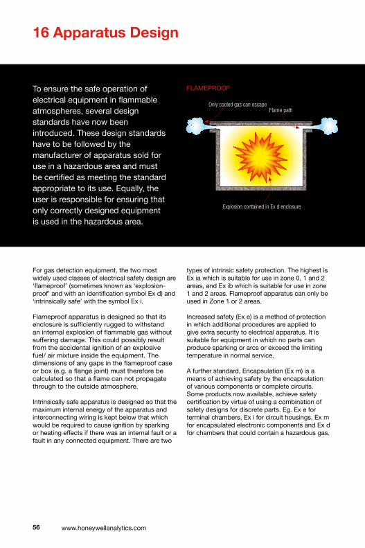
�� www.honeywellanalytics.com
1� Apparatus Design
For gas detection equipment, the two most widely used classes of electrical safety design are ‘flameproof’ (sometimes known as ‘explosion-proof’ and with an identification symbol Ex d) and ‘intrinsically safe’ with the symbol Ex i.
Flameproof apparatus is designed so that its enclosure is sufficiently rugged to withstand an internal explosion of flammable gas without suffering damage. This could possibly result from the accidental ignition of an explosive fuel/ air mixture inside the equipment. The dimensions of any gaps in the flameproof case or box (e.g. a flange joint) must therefore be calculated so that a flame can not propagate through to the outside atmosphere.
Intrinsically safe apparatus is designed so that the maximum internal energy of the apparatus and interconnecting wiring is kept below that which would be required to cause ignition by sparking or heating effects if there was an internal fault or a fault in any connected equipment. There are two
types of intrinsic safety protection. The highest is Ex ia which is suitable for use in zone 0, 1 and 2 areas, and Ex ib which is suitable for use in zone 1 and 2 areas. Flameproof apparatus can only be used in Zone 1 or 2 areas.
Increased safety (Ex e) is a method of protection in which additional procedures are applied to give extra security to electrical apparatus. It is suitable for equipment in which no parts can produce sparking or arcs or exceed the limiting temperature in normal service.
A further standard, Encapsulation (Ex m) is a means of achieving safety by the encapsulation of various components or complete circuits. Some products now available, achieve safety certification by virtue of using a combination of safety designs for discrete parts. Eg. Ex e for terminal chambers, Ex i for circuit housings, Ex m for encapsulated electronic components and Ex d for chambers that could contain a hazardous gas.
R L
C
Flame path
Only cooled gas can escape
Explosion contained in Ex d enclosure
GasketFlame path
To ensure the safe operation of electrical equipment in flammable atmospheres, several design standards have now been introduced. These design standards have to be followed by the manufacturer of apparatus sold for use in a hazardous area and must be certified as meeting the standard appropriate to its use. Equally, the user is responsible for ensuring that only correctly designed equipment is used in the hazardous area.
FLAMEPROOF

��
R L
C
Flame path
Only cooled gas can escape
Explosion contained in Ex d enclosure
GasketFlame path
Division Zone Ex Typeofprotection
1
0
Exia intrinsicallysafe
Exs special(speciallycertified)
1
Anydesignsuitableforzone0plus:
Exd flameproof
Exib intrinsicallysafe
Exp pressurised/continuousdilution
Exe increasedsafety
Exs special
Exm encapsulation
22
Anydesignsuitableforzone1plus:
ExnorN non-sparking(non-incendive)
Exo oil
Exq powder/sandfilled
INTRINSICALLy SAFE INCREASED SAFETy
HazardousAreaDesignStandards
Exsisnotusedinthelateststandardsbutmaybefoundonolderequipmentstillinuse.

�� www.honeywellanalytics.com
As defined by standard No EN50014 of the European Committee for Electrical Standards (i.e. Comite Europeen de Normalisation Electrotechnique or CENELEC), equipment for use in potentially explosive atmospheres is divided into two apparatus groups:
Group Ifor mines which are susceptible to firedamp (Methane)
Group IIfor places with a potentially explosive atmosphere, other than Group I mines
Group II clearly covers a wide range of potentially explosive atmospheres and includes many gases or vapours that constitute widely different degrees of hazard. Therefore, in order to separate more clearly the differing design features required when used in a particular gas or vapour, Group II gases are sub-divided as indicated in the table. Acetylene is often considered to be so unstable that it is listed separately, although still included in Group II gases. A more comprehensive listing
of gases can be found in European Standard EN50014.
The Temperature Class rating for safety equipment is also very important in the selection of devices to detect gas or mixture of gases. (In a mixture of gases, it is always advisable to take the ‘worst case’ of any of the gases in the mixture). Temperature classification relates to the maximum surface temperature which can be allowed for a piece of apparatus. This is to ensure that it does not exceed the ignition temperature of the gases or vapours with which it comes into contact.
The range varies from T1 (450°C) down to T6 (85°C). Certified apparatus is tested in accordance with the specified gases or vapours in which it can be used. Both the apparatus group and the temperature classification are then indicated on the safety certificate and on the apparatus itself.
North America and the IEC are consistent in their temperature or T-Codes. However unlike the IEC, North America includes incremental values as shown opposite.
17 Apparatus Classification
As an aid to the selection of apparatus for safe use in different environmental conditions, two designations, apparatus group and temperature classification, are now widely used to define their limitations.
oC
T6=85
T5=100
T4=135
T3=200
T2=300
T1=450
T6=85
T5=100
T4=135
T3=200
T2=300
T1=450
T4C=120
T3C=160
T3B=165
T3A=180
T2D=215
T2C=230
T2B=260
T2A=280

��
RepresentativeGas GasClassification Ignitability
EuropeandIECcountries USandCanada
Acetylene GroupIIC ClassI,GroupA
Hydrogen GroupIIC ClassI,GroupB
Ethylene GroupIIB ClassI,GroupC
Propane GroupIIA ClassI,GroupD
Methane GroupI Noclassification
Easi
erto
igni
te
oC
T6=85
T5=100
T4=135
T3=200
T2=300
T1=450
T6=85
T5=100
T4=135
T3=200
T2=300
T1=450
T4C=120
T3C=160
T3B=165
T3A=180
T2D=215
T2C=230
T2B=260
T2A=280
Apparatus Group
Temperature Class

�0 www.honeywellanalytics.com
In Europe the designation used to indicate the Ingress Protection consists of the letters IP followed by two ‘Characteristic Numbers’ which indicate the degree of protection. The first number indicates the degree of protection for persons against contact with live or moving parts inside, and the second number shows the enclosure’s protection against entry of water. For example, an enclosure with a rating of IP65 would give complete protection against touching live or
moving parts, no ingress of dust, and would be protected against entry from water spray or jet. This would be suitable for use with gas detection equipment such as controllers, but care should be taken to ensure adequate cooling of the electronics. The two digit IP rating is a short form more commonly used in Britain. The full international version has three digits after the IP rather than two, e.g. “IP653”. The third digit is impact resistance. The meanings of the numbers are given in the following table.
1� Ingress Protection of Enclosures
Coded classifications are now widely used to indicate the degree of protection given by an enclosure against entry of liquids and solid materials. This classification also covers the protection of persons against contact with any live or moving parts inside the enclosure. It should be remembered that this is supplementary to and not an alternative to the protection classifications for electrical equipment used in hazardous areas.
ThirdNumeral Meaning
0 NoProtection
1 Impactof0.225Joule(150gweightdroppedfrom15cm)
2 Impactof0.375Joule(250gweightdroppedfrom15cm)
3 Impactof0.5Joule(250gweightdroppedfrom20cm)
4 (Nomeaning)
5 Impactof2.0Joule(500gweightdroppedfrom40cm)
6 (Nomeaning)
7 Impactof6.0Joule(1.5Kgweightdroppedfrom40cm)
8 H20.00005%
9 Impactof6.0Joule(5Kgweightdroppedfrom40cm)
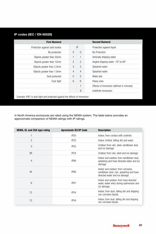
In North America enclosures are rated using the NEMA system. The table below provides an approximate comparison of NEMA ratings with IP ratings.
�1
NEMA,ULandCSAtyperating AproximateIEC/IPCode Description
1 IP20 Indoor,fromcontactwithcontents
2 IP22 Indoor,limited,fallingdirtandwater
3 IP55 Outdoorfromrain,sleet,windblowndustandicedamage
3R IP24 Outdoorfromrain,sleetandicedamage
4
IP66
Indoorandoutdoor,fromwindblowndust,splashingandhosedirectedwaterandicedamage
4X
IP66
Indoorandoutdoor,fromcorrosion,windblowndust,rain,splashingandhosedirectedwaterandicedamage
6
IP67
Indoorandoutdoor,fromhosedirectedwater,waterentryduringsubmersionandicedamage
12 IP54 Indoor,fromdust,fallingdirtanddrippingnoncorrosiveliquids
13 IP54 Indoor,fromdust,fallingdirtanddrippingnoncorrosiveliquids
IP codes (IEC / EN �0���)
SecondNumeral
IP Protectionagainstliquid
00 NoProtection
11 Verticallydrippingwater
22 Angleddrippingwater-75ºto90º
33 Splashedwater
44 Splashedwater
55 Waterjets
66 Heavyseas
7 Effectsofimmersion(definedinminutes)
8 Indefiniteimmersion
Example:IP67isdusttightandprotectedagainsttheeffectsofimmersion
FirstNumeral
Protectionagainstsolidbodies
Noprotection
Objectsgreaterthan50mm
Objectsgreaterthan12mm
Objectsgreaterthan2.5mm
Objectsgreaterthan1.0mm
Dustprotected
Dusttight
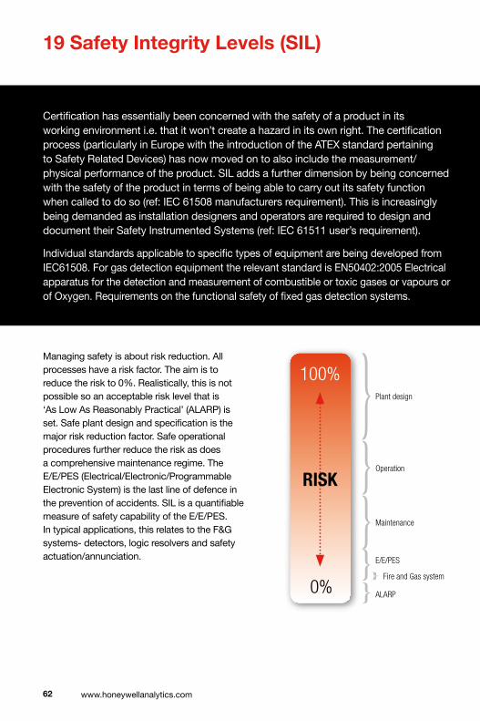
1� Safety Integrity Levels (SIL)
�� www.honeywellanalytics.com
Certification has essentially been concerned with the safety of a product in its working environment i.e. that it won’t create a hazard in its own right. The certification process (particularly in Europe with the introduction of the ATEX standard pertaining to Safety Related Devices) has now moved on to also include the measurement/physical performance of the product. SIL adds a further dimension by being concerned with the safety of the product in terms of being able to carry out its safety function when called to do so (ref: IEC 61508 manufacturers requirement). This is increasingly being demanded as installation designers and operators are required to design and document their Safety Instrumented Systems (ref: IEC 61511 user’s requirement).
Individual standards applicable to specific types of equipment are being developed from IEC61508. For gas detection equipment the relevant standard is EN50402:2005 Electrical apparatus for the detection and measurement of combustible or toxic gases or vapours or of Oxygen. Requirements on the functional safety of fixed gas detection systems.
Managing safety is about risk reduction. All processes have a risk factor. The aim is to reduce the risk to 0%. Realistically, this is not possible so an acceptable risk level that is ‘As Low As Reasonably Practical’ (ALARP) is set. Safe plant design and specification is the major risk reduction factor. Safe operational procedures further reduce the risk as does a comprehensive maintenance regime. The E/E/PES (Electrical/Electronic/Programmable Electronic System) is the last line of defence in the prevention of accidents. SIL is a quantifiable measure of safety capability of the E/E/PES. In typical applications, this relates to the F&G systems- detectors, logic resolvers and safety actuation/annunciation.
Plantdesign
100%
0%
RISKOperation
Maintenance
E/E/PES
FireandGassystem
ALARP

��
It is recognised that all equipment has failure modes. The key aspect is to be able to detect when the failures have occurred and take appropriate action. In some systems, redundancy can be applied to retain a function. In others, self checking can be employed to the same effect. The major design aim is to avoid a situation where a fault which prevents the system carrying out its safety function goes undetected. There is a critical distinction between reliability and safety. A product which appears to be reliable may have unrevealed failure modes whereas a piece of equipment which appears to declare a large number of faults may be safer as it is never/rarely in a condition where it is unable to do its function or has failed to annunciate its inability to do so.
There are 4 levels of SIL defined. In general, the higher the SIL, the greater the number of failure modes that are accommodated. For Fire and Gas systems the levels are defined in terms of “average probability of failure to perform the intended function on demand”.
Many current fire and gas detection products were designed long before the introduction of SIL and therefore on individual assessment may only achieve a low or no SIL rating. This problem can be overcome by techniques such as decreasing the proof test intervals or combining systems with different technologies (and hence eliminating common mode failures) to increase the effective SIL rating.
For a safety system to achieve a specified SIL, the sum of the PFDavg must be considered.
ForSIL2PDF(Sensor)+PFD(Resolver)+PDF(Actuator)<1x10⁻²
The selection of SIL required for the installation must be made in conjunction with the level of safety management within the design of the process itself. The E/E/PES should not be considered the primary safety system. Design, operation and maintenance have the most significant combination to the safety of any industrial process.
LogicResolver
MEASUREMENTRESOLVER,ALARMLEVEL,VOTING
SafetyActuation
SHUTOFFVALVE
Sensor
GASDETECTOR
SIL Probabilityoffailureondemand
1 >10–2to<10–1
2 >10–3to<10–2
3 >10–4to<10–3
4 >10–5to<10–4
Saferequipm
ent

�� www.honeywellanalytics.com
�0 Gas Detection Systems
The most common method employed to continuously monitor for leakage of hazardous gases is to place a number of sensors at the places where any leaks are most likely to occur. These are often then connected electrically to a multi-channel controller located some distance away in a safe, gas free area with display and alarm facilities, event recording devices etc. This is often referred to as a fixed point system. As its name implies, it is permanently located in the area (e.g. an offshore platform, oil refinery, laboratory cold storage etc).
The complexity of any gas detection system depends on the use to which the data will be put. Data recording allows the information to be used to identify problem areas and assist in the implementation of safety measures. If the system is to be used for warnings only, then the outputs from the system can be simple and no data storage is necessary. In choosing a system, therefore, it is important to know how the information will be used so that the proper system components can be chosen. In toxic gas monitoring, the use of multi-point systems has rapidly demonstrated their potential for solving a wide variety of workplace exposure problems and is invaluable for both identifying problems and for keeping workers and management aware of pollutant concentrations in the workplace.
In the design of multi-point systems, considerable thought should be given to the various components and to their interconnection. When using catalytic detection sensors, for instance, the electrical cable connections to the sensors would have three cores, each of 1mm squared, carrying not only the output signal, but also power to the electrical bridge circuit, which is located at the sensor to reduce signal voltage drop along the cables.
In the case of toxic (and some flammable) gas monitoring systems, the atmosphere is often sampled at locations remote from the unit and the gases are drawn by pumps to the sensors through a number of synthetic material, narrow-bore tubes. Care in design of such systems will include selection of suitable sized pumps and tubes, a sequential sampling unit for sampling each tube in turn and filters to stop particulates or water cutting off the flow of gas.
The bore size of tubing can be critical, since it needs to be both large enough to allow rapid response times with standard size pumps, but at the same time should not be so large as to allow excessive dilution of the sample by air. Each sampling point must be connected to a separate tube and if a number of points are connected to a single, central sensor, it will be necessary to purge the sensor with clean air between samples.
The controllers used in fixed systems can be centrally located or distributed at various locations in a facility according to the application requirements. They come in a control panel and come in either single channel (i.e. one control card per sensor) or multi-channel configurations, the latter being useful where power, space or cost limitations are important.
The control units include a front panel meter or LCD to

��
indicate the gas concentration at each sensor and will also normally have internal relays to control functions such as alarm, fault and shutdown. The number of alarm levels available varies between controllers but typically up to three levels can be set, depending on statutory requirements or working practices within the industry. Other useful features would include alarm inhibit and reset, over-range indication and analogue 4-20mA outputs. Often digital outputs are also available for interfacing the controller to a DCS/BMS. It is important to remember that the main purpose of a gas detection system is to detect the build up of a gas concentration before it reaches a hazardous level and to initiate a mitigation process to prevent a hazard occurring. If the gas concentration continues towards a hazardous level then executive shut down and hazard warning alarms are initiated. It is not enough to just log the event or measure the gas levels to which personnel have been exposed.
20m
GD
GD
GD
GD
AV
AV
AVR
F
Gas Detector
Audible & Visual Alarm
Remote Reset
Fused Spur
Control Panel
Key
GD
AV
R
F
Typical small gas detection system protecting a room
cables and junction boxes
In a typical industrial gas detection system such as that just described, sensors are located at a number of strategic points around the plant and at varying distances from the controller. When installing electrical connections to the controller, it is important to remember that each sensor cable will have a different electrical loop resistance depending upon its length. With constant voltage type detectors the calibration process will require a person at both the sensor in the field and at the controller. With constant current detectors or those with a local transmitter, calibration of the field device can be carried out separately to that of the controller. The sensor cables are protected from external damage either by passing them through metal ducting, or by using a suitable
mechanically protected cable. Protective glands have to be fitted at each end of the cable and the sensor is mounted on a junction box to help in making simple, low-resistance, ‘clean’ terminations. It is also very important to ensure that all the gland sizes and screw threads are compatible with the junction box and the external diameter of the cables being used. The correct sealing washer should be used to ensure a weatherproof between the detector and junction box. A further point to remember is that sensor manufacturers normally indicate the maximum loop resistance (not line resistance) of their sensor connections when providing the information to calculate cable core diameters for installation.
Eg.• Small Pump Station• Generator House• Normally Unmanned
Alarms• Warning AV prior to entry• AV internal to evacuate (if occupied)• Remote reset to silence alarm
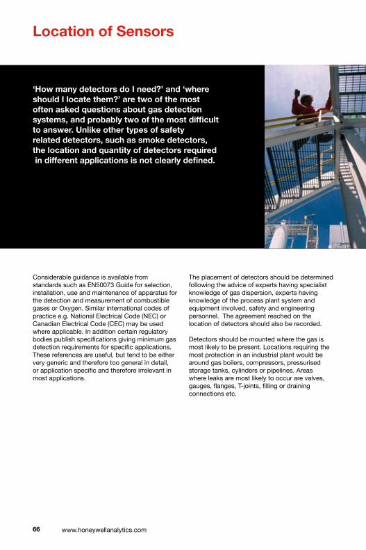
�� www.honeywellanalytics.com
Location of Sensors
‘How many detectors do I need?’ and ‘where should I locate them?’ are two of the most often asked questions about gas detection systems, and probably two of the most difficult to answer. Unlike other types of safety related detectors, such as smoke detectors, the location and quantity of detectors required in different applications is not clearly defined.
Considerable guidance is available from standards such as EN50073 Guide for selection, installation, use and maintenance of apparatus for the detection and measurement of combustible gases or Oxygen. Similar international codes of practice e.g. National Electrical Code (NEC) or Canadian Electrical Code (CEC) may be used where applicable. In addition certain regulatory bodies publish specifications giving minimum gas detection requirements for specific applications. These references are useful, but tend to be either very generic and therefore too general in detail, or application specific and therefore irrelevant in most applications.
The placement of detectors should be determined following the advice of experts having specialist knowledge of gas dispersion, experts having knowledge of the process plant system and equipment involved, safety and engineering personnel. The agreement reached on the location of detectors should also be recorded.
Detectors should be mounted where the gas is most likely to be present. Locations requiring the most protection in an industrial plant would be around gas boilers, compressors, pressurised storage tanks, cylinders or pipelines. Areas where leaks are most likely to occur are valves, gauges, flanges, T-joints, filling or draining connections etc.
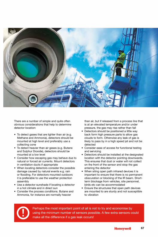
��
Perhaps the most important point of all is not to try and economise by using the minimum number of sensors possible. A few extra sensors could make all the difference if a gas leak occurs!!
There are a number of simple and quite often obvious considerations that help to determine detector location:
• To detect gases that are lighter than air (e.g. Methane and Ammonia), detectors should be mounted at high level and preferably use a collecting cone
• To detect heavier than air gases (e.g. Butane and Sulphur Dioxide), detectors should be mounted at a low level
• Consider how escaping gas may behave due to natural or forced air currents. Mount detectors in ventilation ducts if appropriate
• When locating detectors consider the possible damage caused by natural events e.g. rain or flooding. For detectors mounted outdoors it is preferable to use the weather protection assembly
• Use a detector sunshade if locating a detector in a hot climate and in direct sun
• Consider the process conditions. Butane and Ammonia, for instance are normally heavier
than air, but if released from a process line that is at an elevated temperature and/or under pressure, the gas may rise rather than fall
• Detectors should be positioned a little way back form high pressure parts to allow gas clouds to form. Otherwise any leak of gas is likely to pass by in a high speed jet and not be detected
• Consider ease of access for functional testing and servicing
• Detectors should be installed at the designated location with the detector pointing downwards. This ensures that dust or water will not collect on the front of the sensor and stop the gas entering the detector
• When siting open path infrared devices it is important to ensure that there is no permanent obscuration or blocking of the IR beam. Short-term blockage from vehicles, site personnel, birds etc can be accommodated
• Ensure the structures that open path devices are mounted to are sturdy and not susceptible to vibration

�� www.honeywellanalytics.com
Typical Sensor Mounting Options
duct mountedceiling mounted
pole mountedWall mounted
REMOTE GASSING
gastubing
gassing pointassembly
TYPICAL SENSOR/CONTROLLER/ALARM SYSTEM
control system in safe areacontrol room
controllerPLC/DCS
hazardous areain the field
CEILING MOUNT
mountingplate
junction box/transmitter
screws/bolts
sensor
DUCT MOUNT
weatherprotectionassembly
junction box/transmitter
gastubing
duct
gassingpoint
POLE MOUNT
junction box/transmitter
pole
sensor
metal clamps
bolts
REMOTE SENSORLOCAL DISPLAY& GASSING
gastubing
gassing pointassembly
localdisplay
weatherprotection withgassing nozzle
remotesensor
remotesensor
cable
TYPICAL LOCAL ALARM SYSTEM
local relaysin transmitter
optional audible/visual alarm
controllerPLC/DCS
locally drivenaudible/visual alarm
WALL MOUNT
STANDALONE SYSTEM
audible/visualalarm
indoors outdoors
SAMPLING/ASPIRATING SYSTEM
DA N G E R2 4 0 VO LT S
calibration
sample in
exhaust
pump
audible/visualalarm
intrinsicallysafe system
local relaysin transmitter
REMOTE GASSING
gastubing
gassing pointassembly
TYPICAL SENSOR/CONTROLLER/ALARM SYSTEM
control system in safe areacontrol room
controllerPLC/DCS
hazardous areain the field
CEILING MOUNT
mountingplate
junction box/transmitter
screws/bolts
sensor
DUCT MOUNT
Weather protection
assembly with gassing nozzle
junction box/transmitter
gastubing
duct
gassingpoint
POLE MOUNT
junction box/transmitter
pole
sensor
metal clamps
bolts
REMOTE SENSORLOCAL DISPLAY& GASSING
gastubing
gassing pointassembly
localdisplay
weatherprotection withgassing nozzle
remotesensor
remotesensor
cable
TYPICAL LOCAL ALARM SYSTEM
local relaysin transmitter
optional audible/visual alarm
controllerPLC/DCS
locally drivenaudible/visual alarm
WALL MOUNT
STANDALONE SYSTEM
audible/visualalarm
indoors outdoors
SAMPLING/ASPIRATING SYSTEM
DA N G E R2 4 0 VO LT S
calibration
sample in
exhaust
pump
audible/visualalarm
intrinsicallysafe system
local relaysin transmitter

��
REMOTE GASSING
gastubing
gassing pointassembly
TYPICAL SENSOR/CONTROLLER/ALARM SYSTEM
control system in safe areacontrol room
controllerPLC/DCS
hazardous areain the field
CEILING MOUNT
mountingplate
junction box/transmitter
screws/bolts
sensor
DUCT MOUNT
weatherprotectionassembly
junction box/transmitter
gastubing
duct
gassingpoint
POLE MOUNT
junction box/transmitter
pole
sensor
metal clamps
bolts
REMOTE SENSORLOCAL DISPLAY& GASSING
gastubing
gassing pointassembly
localdisplay
weatherprotection withgassing nozzle
remotesensor
remotesensor
cable
TYPICAL LOCAL ALARM SYSTEM
local relaysin transmitter
optional audible/visual alarm
controllerPLC/DCS
locally drivenaudible/visual alarm
WALL MOUNT
STANDALONE SYSTEM
audible/visualalarm
indoors outdoors
SAMPLING/ASPIRATING SYSTEM
DA N G E R2 4 0 VO LT S
calibration
sample in
exhaust
pump
audible/visualalarm
intrinsicallysafe system
local relaysin transmitter
Typical System Configurations
locally dRiven alaRm systemRemote sensoR, local display/gassing
standalone systemtypical sensoR/contRolleR system
typical sampling/aspiRating system
REMOTE GASSING
gastubing
gassing pointassembly
TYPICAL SENSOR/CONTROLLER/ALARM SYSTEM
control system in safe areacontrol room
controllerPLC/DCS
hazardous areain the field
CEILING MOUNT
mountingplate
junction box/transmitter
screws/bolts
sensor
DUCT MOUNT
weatherprotectionassembly
junction box/transmitter
gastubing
duct
gassingpoint
POLE MOUNT
junction box/transmitter
pole
sensor
metal clamps
bolts
REMOTE SENSORLOCAL DISPLAY& GASSING
gastubing
gassing pointassembly
localdisplay
weatherprotection withgassing nozzle
remotesensor
remotesensor
cable
TYPICAL LOCAL ALARM SYSTEM
local relaysin transmitter
optional audible/visual alarm
controllerPLC/DCS
locally drivenaudible/visual alarm
WALL MOUNT
STANDALONE SYSTEM
audible/visualalarm
indoors outdoors
SAMPLING/ASPIRATING SYSTEM
DA N G E R2 4 0 VO LT S
calibration
sample in
exhaust
pump
audible/visualalarm
intrinsicallysafe system
local relaysin transmitter

�0 www.honeywellanalytics.com
Cable Systems
These are mainly used in Europe (although the US and Canadian Electrical Codes list Metal Clad and Mineral Insulated cables for use in Class 1 Div 1 or Zone 1). Explosionproof standards state that cable systems with suitable mechanical protection must be used. The cable is often Steel Wire Armoured (SWA) if used in areas where mechanical damage may occur, or it may be laid in protective conduit which is open at both ends. Certified cable glands are used to safely connect the cable to the enclosure.
Indirect Cable Entry
Indirect entry is into an increased safety ‘Ex e’ terminal area. Line barriers are used on the wires between the terminal chamber and the main enclosure. The installer need only open access the terminal area, not the flameproof enclosure.
Installation Methods
Essentially three installation methods are used Worldwide for electrical equipment in hazardous locations:
1. Cable with indirect entry
2. Cable with direct entry
3. Conduit
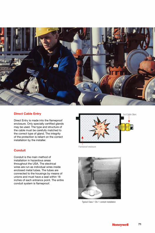
�1
Direct Cable Entry
Direct Entry is made into the flameproof enclosure. Only specially certified glands may be used. The type and structure of the cable must be carefully matched to the correct type of gland. The integrity of the protection is reliant on the correct installation by the installer.
Conduit
Conduit is the main method of installation in hazardous areas throughout the USA. The electrical wires are run as individual wires inside enclosed metal tubes. The tubes are connected to the housings by means of unions and must have a seal within 18 inches of each entrance point. The entire conduit system is flameproof.
TypicalClass1Div1conduitinstallation
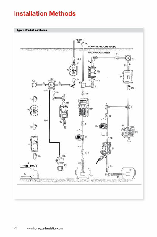
�� www.honeywellanalytics.com
TypicalConduitInstallation
Installation Methods

��
ConduitSeals
Boxes
Horizontal Seal
Vertical Seal with Drain
Packing Fiber Sealing Compound
Wires
Drain Channel
Packing FiberConduit
Drain
Sealing Compound
Plug
FittingsandSealsforConduit
EXGJH/EXLK UNY
The seals prevent any explosions in the tubing from spreading. Drains must be installed at low points where condensation may accumulate.
EYS ELF
EYM EYDM
GR GRF
CPUGRSS
�� www.honeywellanalytics.com
�1 Global Service and Support Network
A vital part of ensuring that fixed and portable gas detection equipment operates correctly is periodic servicing, maintenance and calibration. Unlike some other types of safety related equipment (e.g. fire detection), gas detection does not have specific legislation or clear guidelines that specify how often it should be serviced. Relevant documents simply state that inspection and maintenance should be carried out frequently by competent, trained personnel and in line with the manufacturers recommendations.
Gas detection applications vary widely and therefore so do the factors that affect the frequency of servicing required to ensure proper operation. It is important that a suitable service period is established for the equipment that takes account of each individual application’s unique set of factors.
Traditionally, gas detection users had their own in-house service departments that were responsible for servicing, maintenance and calibration of their gas detection equipment as well as other safety related equipment. Increasingly, many users now choose to outsource part or all of this function in order to reduce fixed costs and at the same time ensure that people with specialist knowledge of the equipment are responsible for it.
It is also becoming more common for leading gas detection companies to also offer service of third party gas detection equipment as well as their own. As users continue to demand better efficiencies from outsourced suppliers, the trend in the future is likely to require gas detection companies to offer a ‘one stop shop’ for the service and maintenance of complete safety systems.
Gas detection company service departments should also offer other services including site surveys, installation, commissioning and training. Advice from experts in gas detection when conducting a site survey helps ensure the selection of the most suitable detection technologies and most appropriate detector locations. Installation must be carried out in accordance with any site, local or national codes of practice and legislation.

��
Properly commissioning a system ensures that it is fully functioning as designed and accurately detecting gas hazards. Many companies require that employees who use personal gas detection equipment, or work in areas that have fixed systems installed, are formally trained on the use and routine maintenance of the equipment. Service training departments should be able to offer certified training courses designed to suit all levels of ability from basic gas detection principles through to advanced custom designed technical courses.
Some gas detectors now offer ‘smart’ sensors that are pre-calibrated and can be simply fitted and used without the need for additional calibration and set up in the field. The additional use of Intrinsically
Safe (I.S) design can also allow the ‘hot swap’ of these sensors without the need for removing power from the detector. Other recent innovations include the use of ‘auto-cal’ routines where the user is taken through a sequence of ‘on-screen’ calibration steps thereby ensuring correct set up. All of these innovations help keep service times to a minimum while ensuring accurate calibration of the detector.
The modular design of modern gas detectors enables more efficient servicing. The replacement of modules rather than component level service/repair greatly reduces turnaround time and therefore system down time. The economies of scale achieved by volume module level servicing also enables overall servicing costs to be reduced.
Take your service to the next level
Asia +�� ���� ��01Europe +�1 �� ��� ��00Americas +1 �00 ��� �000

�� www.honeywellanalytics.com
Glossary
ACGIH AmericanConferenceofGovernmentalIndustrialHygienists.
AIT AutoIgnitionTemperature.
Analogue/analogoutput StandardmAoutputfromasensorortransmitter.Normallydescribedas4-20mA.ThealternativeisamVbridgeoutputfromacatalytictypesensororadigitaloutput.
Apparatusgroup Theclassificationofflammablegasesintogroupsthatareassociatedwithrequiredapparatusdesignstandards.
Asphyxiation DeathresultingfromlackofOxygen.
ATEX EuropeanExplosiveAtmospheresDirectives(ATmospheresEXplosibles).
Baseefa British Approvals Service for Electrical Equipment in Flammable Atmospheres – UKSafetyCertification.
BMS BuildingManagementSystem.
Binarymixtureofgas Amixtureoftwogasesonly.
BreathingZone Heightwheretoxicgasmonitoringisoftencarriedout-headheight.
BridgeCircuit WheatstoneBridgecircuitusedincatalyticdetectordesign.
CASnumber ChemicalAbstractsService.CASRegistrynumberusedtoidentifysubstanceswithouttheambiguityofchemicalnomenclature.
Calibration Theprocessofadjustingtheoutputofthedetectortogiveanaccuratereadingofgasconcentrationoveritsmeasuringrange.
Carcinogenic CapableofcausingCancer.
CatalyticSensor Fordetectionofcombustiblegases.Thesearemadeofanelectricallyheatedplatinumwirecoil,coveredfirstwithaceramicbasesuchasaluminaandthenwithafinaloutercoatingofpalladiumorrhidiumcatalystdispersedinasubstrateofthoria.
CE IndicatescompliancetoallrelevantEuropeandirectives.
CEC CanadianElectricalCode.
Cell Anindividualsensor.
CENELEC Comite Europeen de Normalisation Electrotechnique – European Safety Certification.
Cesi Centro Electrotechnico Sperimentale Italiano – Italian Safety Certification.
Channel Onelineorpointofgasdetection.
Chemcassette® Registerednameofapapertapecartridgeusedintoxicgasanalysers.
Conduit MetaltubingmainlyusedintheUSforinstallationofwiresinhazardousareas.
COSHH ControlofSubstancesHazardoustoHealth.
CSA CanadianStandardsAssociation.
dBA Decibels,relativetotheAweightingscale(asaffectedbythehumanear).
DCS DistributedControlSystem.
DomesticGasDetector Gasdetectordesignedspecificallyforuseindomesticorresidentialproperties.
Division NorthAmericanareaclassificationofahazardousarea(Division1or2)thatdefinesthelengthoftimeahazardinpresent.
ElectrochemicalSensor Agassensitiveelectrode,formedbyapermeablemembraneandspecialelectrolyte.
EMC Electromagneticcompatibility.
ESD Electrostaticdischarge.
�� Glossary

��
Exd Flameproof – any flame is contained within the housing of the product. Suitableforzones1&2.
Exi Intrinsic safety – any ignition is limited due to the low energy in the circuit even with onefault(Exib)ortwofaults(Exib).Zones0,1&2.
Exe Increased safety – No sparks or hot surfaces. Zones 1 & 2.
Exm Encapsulatedtokeepgasoutofproduct.Zones1&2.
Explosimeters Combustiblegasmonitor.
ExplosionProof AnameforExdapparatusdesign.
FailSafe Descriptionofadetectorthathasnounseenfailuremodes.
Fieldbus Digitalcommunicationstandard.
Firedamp AmixtureofmethaneandotherHydrocarbongasesthatformsincoalmines.
Fixedpointsystem Gasdetectionsystemusingindividualfixedpointgassensorsand/ortransmitters.Notmobileortransportable.
Flamearrestor Astructurethatallowsgastodiffusethroughitintoadetectorbutpreventspropagationofanyflamebackout.
Flameproof AnameforExdapparatusdesign.
FlammableRange Bandofgas/airmixturethatproducesthatisflammable.
FlashPoint Thisisthelowesttemperatureatwhichvapourisgivenoffatsufficientratetoformanexplosivemixturewithair.
FM Factory Mutual – USA Safety Certification.
GasAnalyzer Normallyreferstoequipmentusedtomeasureextremelysmallconcentrationsofgas(loworsubppm)oronespecificgasinthepresenceofseveralothers.
GasDetector Referstoequipmentusedinapplicationswherethereisnormallynotoxicorexplosivegasriskandthereforeisusedtosignalthepresenceofgasinotherwisesafeconditions.
GasMonitor Equipmentusedinapplicationswhereagasorgasmixtureisconstantlypresentandisthereforeusedtosignalachangeintheconcentrationormixtureofthegas.
GOSST Russianhazardousareaapprovalsbody.WidelyacceptedineasternEuropeorasabaseforownlocalapprovals.
HazardousAreas Areaswherethereisthepossibilityofthepresenceofanexplosivemixtureofflammable gas or vapour and air are known as ‘Hazardous’ and other areas as ‘safe’ or ‘non-hazardous’. Any electrical equipment used in hazardous areas must be testedandapprovedtoensurethat,inuseevenunderfaultconditions,itcannotcauseanexplosion.
HSE HealthandSafetyExecutive(UK)
IgnitionTemperature Thelowesttemperaturethatwillcauseamixturetoburnorexplode.
Ineris Institut Nationale de L’Environment Industriel et des Riscues.
InfraredDetector GasDetectorthatusestheprinciplethatinfraredlightisabsorbedbygasmoleculesatspecificfrequencies.
InternationalElectrotechnical InternationalStandardsandconformityassessmentforgovernment,businessandCommittee societyforallelectrical,electronicandrelatedtechnologies.
Intrinsicallysafe(IS) Methodofdesignsothatthemaximuminternalenergyoftheapparatusandwiringisnotsufficienttocauseignitionbysparkingorheatingeffectsresultingfromafault.
IP Ingress Protection – a measure of protection against the ingress of dust and water.
Kema HazardousAreaApprovalsBody.DutchSafetyCertification.
Glossarycontinued

�� www.honeywellanalytics.com
LCD LiquidCrystalDisplay.
LED LightEmittingDiode.
LEL Lower Explosive Limit – is the lowest concentration of ‘fuel’ in air which will burn and formostflammablegasesandvapoursitislessthan5%byvolume.
LEL% PercentageoftheLowerExplosiveLimit(forexample,10%LELofMethaneisapprox0.5%byvolume).
LELmetres Scaleformeasurementforflammablegasesbyopenpathinfrareddetectors.
LFL LowerFlammableLimit.
LNG LiquefiedNaturalGas.
LPG LiquefiedPetroleumGasmadeupofPropaneandButane.
LTEL LongTermExposureLimit.The8hourLTEListhetime-weightedaverageconcentrationforanormal8hourdaytowhichmostworkersmayberepeatedlyexposed,dayafterday,withoutadverseeffect.
mA Milliamp – measurement of current.
MAC ToxicgasleveldescribedbyACGIH-MaximumAllowableConcentrations(replacedbyTLVs)
MAK MaximaleArbeitsplatzKonzentration.
MEL Maximumexposurelimit.
Milligramspercubicmetre Alternativescaleofmeasurementfortoxicgases.
Modbus Digitalcommunicationprotocol.
multi-channel Morethanonegaschannel.
Multigas Portablegasdetectorwithtypicallyupto4gassensorsfitted.
mV Millivolt – measurement of Voltage.
NaturalGas FossilfuelformedalmostentirelyofMethane.
NEC500 NationalElectricalCode(US).
NEC505 LatestversionofNEC.
NEMA NationalElectricalManufacturersAssociation.USstandardsdevelopingorganisation.NEMAratingofenclosuresissimilartotheIPratingsystem.
NRTLs NationallyRecognisedTestingLaboratories(US).
OEL Occupational Exposure Limit – The 8 hour OEL is the time-weighted average concentrationforanormal8hourdayor40hourworkingweektowhichmostworkersmayberepeatedlyexposed,dayafterday,withoutadverseeffect.
Openpath Infraredgasdetectionwithtransmitterandreceiverdeviceslocatedatadistanceapart.
OSHAandNIOSH OccupationalSafetyandHealthAssociation.
OxygenDeficiency Concentrationsofoxygenlessthan20.9%V/V.
Oz Ounce(weight).
Peak Maximum,orminimum,measurementsinceswitchon.
PerimeterMonitoring Monitoringtheouteredgeofaplantorstorageareaasopposedtomonitoringspecificpoints.
Pellistor Registered trade name for a commercial device – A very small sensing element used in catalytic sensors and sometimes also called a ‘bead’ or a ‘siegistor’.
PLC ProgrammableLogicController.
Glossarycontinued
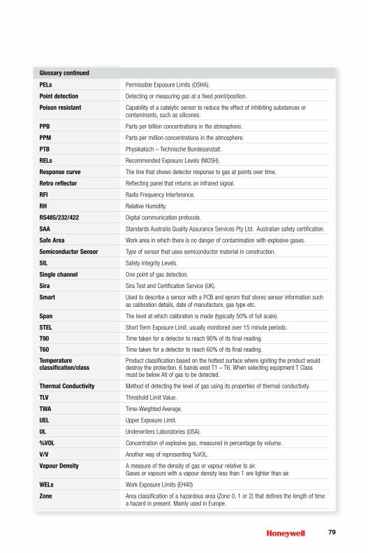
��
PELs PermissibleExposureLimits(OSHA).
Pointdetection Detectingormeasuringgasatafixedpoint/position.
Poisonresistant Capabilityofacatalyticsensortoreducetheeffectofinhibitingsubstancesorcontaminants,suchassilicones.
PPB Partsperbillionconcentrationsintheatmosphere.
PPM Partspermillionconcentrationsintheatmosphere.
PTB Physikalisch – Technische Bundesanstalt.
RELs RecommendedExposureLevels(NIOSH).
Responsecurve Thelinethatshowsdetectorresponsetogasatpointsovertime.
Retroreflector Reflectingpanelthatreturnsaninfraredsignal.
RFI RadioFrequencyInterference.
RH RelativeHumidity.
RS485/232/422 Digitalcommunicationprotocols.
SAA StandardsAustraliaQualityAssuranceServicesPtyLtd.Australiansafetycertification.
SafeArea Workareainwhichthereisnodangerofcontaminationwithexplosivegases.
SemiconductorSensor Typeofsensorthatusessemiconductormaterialinconstruction.
SIL SafetyIntegrityLevels.
Singlechannel Onepointofgasdetection.
Sira SiraTestandCertificationService(UK).
Smart UsedtodescribeasensorwithaPCBandepromthatstoressensorinformationsuchascalibrationdetails,dateofmanufacture,gastypeetc.
Span Thelevelatwhichcalibrationismade(typically50%offullscale).
STEL ShortTermExposureLimit,usuallymonitoredover15minuteperiods.
T90 Timetakenforadetectortoreach90%ofitsfinalreading.
T60 Timetakenforadetectortoreach60%ofitsfinalreading.
Temperature Productclassificationbasedonthehottestsurfacewhereignitingtheproductwouldclassification/class destroy the protection. 6 bands exist T1 – T6. When selecting equipment T Class
mustbebelowAItofgastobedetected.
ThermalConductivity Methodofdetectingthelevelofgasusingitspropertiesofthermalconductivity.
TLV ThresholdLimitValue.
TWA Time-WeightedAverage.
UEL UpperExposureLimit.
UL UnderwritersLaboratories(USA).
%VOL Concentrationofexplosivegas,measuredinpercentagebyvolume.
V/V Anotherwayofrepresenting%VOL.
VapourDensity Ameasureofthedensityofgasorvapourrelativetoair.Gasesorvapourswithavapourdensitylessthan1arelighterthanair.
WELs WorkExposureLimits(EH40)
Zone Areaclassificationofahazardousarea(Zone0,1or2)thatdefinesthelengthoftimeahazardinpresent.MainlyusedinEurope.
Glossarycontinued

�0 www.honeywellanalytics.com
Notes

�1

�� www.honeywellanalytics.com
Notes

��

H_Gasbook_V3
05/07
© 2007 Honeywell Analytics
PleaseNote:Whileeveryefforthasbeenmadetoensureaccuracyinthispublication,noresponsibilitycanbeacceptedforerrorsoromissions.Datamaychange,aswellaslegislation,andyouarestronglyadvisedtoobtaincopiesofthemostrecentlyissuedregulations,standards,andguidelines.Thispublicationisnotintendedtoformthebasisofacontract.
1129
6
Find out more
Contact Honeywell Analytics:
www.honeywellanalytics.com
Europe, Middle East, Africa
Life Safety Distribution AG
Wilstrasse 11-U11
CH-8610 Uster
Switzerland
Tel: +41 (0)44 943 4300
Fax: +41 (0)44 943 4398
Americas
Honeywell Analytics Distribution, Inc.
400 Sawgrass Corporate Pkwy
Suite 230
Sunrise, FL 33325
USA
Tel: +1 954 514 2700
Toll free: +1 800 538 0363
Fax: +1 954 514 2784
www.honeywell.com
Technical [email protected]
Asia Pacific Honeywell Analytics Asia Pacific #508, Kolon Science Valley (1) 187-10 Guro-Dong, Guro-Gu Seoul, 152-050, Korea Tel: +82 (0)2 2025 0307 Fax: +82 (0)2 2025 [email protected]