gas barrier installation method - principal building … barrier installation method: general: the...
TRANSCRIPT

Guidance for Construction on Gas Contamina
Guidance for Construction on Gas
Contaminated Land and
Guidelines for Gas
Land and
Barrier Systems
Guidance for Construction on Gas Contamina
Guidance for Construction on Gas
Contaminated Land and
Guidelines for Gas Barrier Systems
Land and Installation Guidelines for Gas
Barrier Systems
Guidance for Construction on Gas
Contaminated Land and Installation
Guidelines for Gas Barrier SystemsGuidance for Construction on Gas Contamina
Guidance for Construction on Gas
Contaminated Land and Installation
Barrier Systems
Installation Guidelines for Gas
Guidance for Construction on Gas
Contaminated Land and Installation
Guidelines for Gas Barrier Systems
Guidance for construction of new dwellings on gas contaminated land.
Assessing the risk:
It is a requirement of National Planning Policy Framework and Building Regulations Approved Document
C, that where the proposed structure is at risk from gas contaminated land, the developer must carry
out a risk assessment for submission to the local planning authority. The types of ground gasses
commonly encountered are:
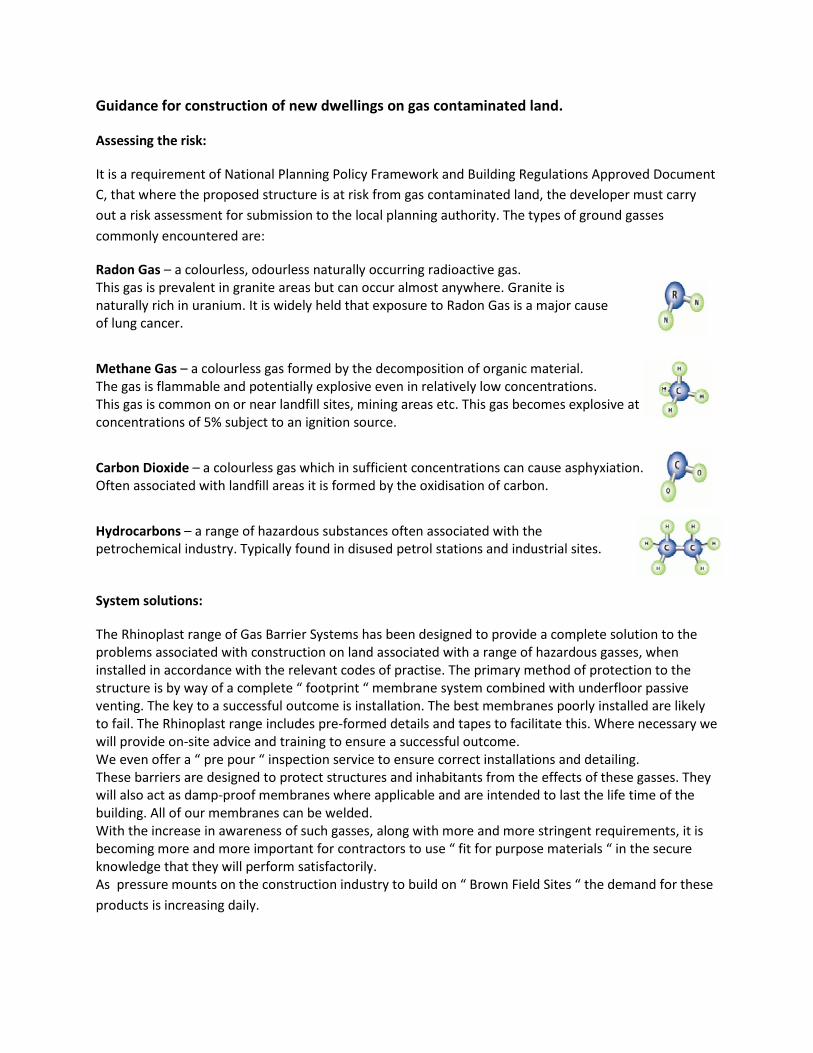
Radon Gas – a colourless, odourless naturally occurring radioactive gas.
This gas is prevalent in granite areas but can occur almost anywhere. Granite is
naturally rich in uranium. It is widely held that exposure to Radon Gas is a major cause
of lung cancer.
Methane Gas – a colourless gas formed by the decomposition of organic material.
The gas is flammable and potentially explosive even in relatively low concentrations.
This gas is common on or near landfill sites, mining areas etc. This gas becomes explosive at
concentrations of 5% subject to an ignition source.
Carbon Dioxide – a colourless gas which in sufficient concentrations can cause asphyxiation.
Often associated with landfill areas it is formed by the oxidisation of carbon.
Hydrocarbons – a range of hazardous substances often associated with the
petrochemical industry. Typically found in disused petrol stations and industrial sites.
System solutions:
The Rhinoplast range of Gas Barrier Systems has been designed to provide a complete solution to the
problems associated with construction on land associated with a range of hazardous gasses, when
installed in accordance with the relevant codes of practise. The primary method of protection to the
structure is by way of a complete “ footprint “ membrane system combined with underfloor passive
venting. The key to a successful outcome is installation. The best membranes poorly installed are likely
to fail. The Rhinoplast range includes pre-formed details and tapes to facilitate this. Where necessary we
will provide on-site advice and training to ensure a successful outcome.
We even offer a “ pre pour “ inspection service to ensure correct installations and detailing.
These barriers are designed to protect structures and inhabitants from the effects of these gasses. They
will also act as damp-proof membranes where applicable and are intended to last the life time of the
building. All of our membranes can be welded.
With the increase in awareness of such gasses, along with more and more stringent requirements, it is
becoming more and more important for contractors to use “ fit for purpose materials “ in the secure
knowledge that they will perform satisfactorily.
As pressure mounts on the construction industry to build on “ Brown Field Sites “ the demand for these
products is increasing daily.
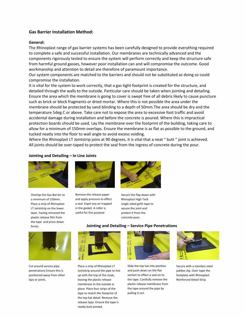
Gas Barrier Installation Method:
General:
The Rhinoplast range of gas barrier systems has been carefully designed to provide everything required
to complete a safe and successful installation. Our membranes are technically advanced and the
components rigorously tested to ensure the system will perform correctly and keep the structure safe
from harmful ground gasses, however poor installation can and will compromise the outcome. Good
workmanship and attention to detail are therefore of paramount importance.
Our system components are matched to the barriers and should not be substituted as doing so could
compromise the installation.
It is vital for the system to work correctly, that a gas tight footprint is created for the structure, and
detailed through the walls to the outside. Particular care should be taken when jointing and detailing.
Ensure the area which the membrane is going to cover is swept free of all debris likely to cause puncture
such as brick or block fragments or dried mortar. Where this is not possible the area under the
membrane should be protected by sand blinding to a depth of 50mm.The area should be dry and the
temperature 5deg.C or above. Take care not to expose the area to excessive foot traffic and avoid
accidental damage during installation and before the concrete is poured. Where this is impractical
protection boards should be used. Lay the membrane over the footprint of the building, taking care to
allow for a minimum of 150mm overlaps. Ensure the membrane is as flat as possible to the ground, and
tucked neatly into the floor to wall angle to avoid excess voiding.
Where the Rhinoplast LT Jointstrip joins at 90 degrees, it is vital that a neat “ butt “ joint is achieved.
All joints should be over-taped to protect the seal from the ingress of concrete during the pour.
Jointing and Detailing – In Line Joints
Jointing and Detailing – Service Pipe Penetrations
Overlap the Gas Barrier to
a minimum of 150mm.
Place a strip of Rhinoplast
LT Jointstrip on the lower
layer, having removed the
plastic release film from
the tape and press down
firmly.
Secure the flap down with
Rhinoplast High Tack
single sided girth tape to
secure the joint and
protect it from the
concrete pour.
Remove the release paper
and apply pressure to effect
a seal. Expel any air trapped
in the gasket. A roller is
useful for this purpose
Cut around service pipe
penetrations Ensure this is
positioned away from other
laps or joints.
Place a strip of Rhinoplast LT
Jointstrip around the pipe to line
up with the top of the cloak,
leaving the plastic release
membrane to the outside in
place. Place four strips of the
tape to match the footprint of
the top hat detail. Remove the
release tape. Ensure the tape is
neatly butt jointed.
Slide the top hat into position
and push down on the flat
section to effect a seal on to
the tape. Carefully remove the
plastic release membrane from
the tape around the pipe by
pulling it out.
Secure with a stainless steel
jubilee clip. Over-tape the
footplate with Rhinoplast
Reinforced Detail Strip.
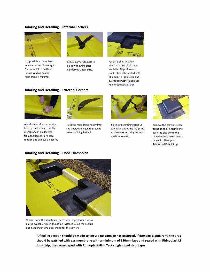
Jointing and Detailing – Internal Corners
Jointing and Detailing – External Corners
Jointing and Detailing – Door Thresholds
It is possible to complete
internal corners by using a
“ hospital fold “ method.
Ensure voiding behind
membrane is minimal
Secure corners to hold in
place with Rhinoplast
Reinforced Detail Strip.
For ease of installation,
internal corner cloaks are
available. All preformed
cloaks should be sealed with
Rhinoplast LT Jointstrip and
over taped with Rhinoplast
Reinforced Detail Strip.
A preformed cloak is required
for external corners. Cut the
membrane at 45 degrees
from the corner to release
tension and achieve a neat fit.
Tuck the membrane neatly into
the floor/wall angle to prevent
excess voiding behind.
Place strips of Rhinoplast LT
Jointstrip under the footprint
of the cloak ensuring corners
are butt jointed.
Remove the brown release
paper on the Jointstrip and
push the cloak onto the
tape to effect a seal. Over -
tape with Rhinoplast
Reinforced Detail Strip.
Where door thresholds are necessary, a preformed cloak
pair is available which should be installed using the sealing
and detailing method described for the corners.
A final inspection should be made to ensure no damage has occurred. If damage is apparent, the area
should be patched with gas membrane with a minimum of 150mm laps and sealed with Rhinoplast LT
Jointstrip, then over-taped with Rhinoplast High Tack single sided girth tape.

Recommended Gas Barrier Application Chart
BRE211 NHBC NHBC
Radon Amber 1 CS2 Amber 2 CS3 CO2 Hydrocarbon Fluid
Gas (methane) Hydrocarbons
Rhinoplast Ultra ���� ���� ���� ���� ���� ����
Rhinoplast Super ���� ���� ����** ���� ���� ����
Rhinoplast Amber 2000 ���� ���� ����** ���� ���� ����
Rhinoplast TGB ���� ���� ����** ���� ���� ����
Rhinoplast Geomembrane ���� ���� ����** ���� ���� ����
* Vapours only
** Independent Inspection Required
Note, all membranes must be installed in accordance with BRE211 ( radon ) or BRE414 ( Ground Gas )
NHBC traffic light risk assessment designated Red would not normally be suitable for low rise housing
development, without further remedial action and assessments.
Useful references: The Building Regulations Approved Document Part C 2004, CP 102:
1973 Code of practice for the protection of buildings against water from
the ground.
BR211 “ Radon – Guidance on protective measures for new buildings “
BRE414 “Protective measures for housing on gas-contaminated land “
CIRIA 665 Ground gas handbook 2009.
BS8485:2007 Code of Practice for the Characterization and Remediation
from Ground Gas in Affected Developments
NHBC “ Guidance on methane and carbon dioxide “ and technical extra
July 2012, issue 7.

System Membranes and Components
Rhinoplast Ultra: A monolithic LDPE barrier designed primarily for use with Radon gas.
Fully Radon gas tested and approved by NSAI ( IAB ) Meets the requirements of BRE211.
Standard roll size 4 x 20 metres. available in red or grey.
Rhinoplast Super: A monolithic hybrid co-
Fully tested for Radon, Methane and CO2. Approved by NSAI ( IAB )
Exceeds the requirements of BRE211 and BRE414.
colour: yellow. Thickness 375mu ( 1500 gge )
Rhinoplast Amber 2000: A monolithic LDPE
Primarily designed for commercial/industrial developments,
Amber 2 ( gas contaminated land ) Colour: light grey, roll size 4 x 12.5 metres.
Thickness 500mu ( 2000 gge )
Rhinoplast TGB: (Total Gas Barrier) . Excellent gas resistant properties due to the integral aluminium foil.
Laminated construction includes reinforcing mesh to improve tear propagation
Designed as a high performance barrier for all applications except hydrocarbon liquids.
Roll size: 2 x 50 metres.
Rhinoplast Geomembrane: An HDPE membrane designed to withstand the
effects of fluid hydrocarbons.
Colour: black. Available in 1mm and 1.5mm thicknesses.
Rhinoplast LT Jointstrip: A butyl modified double sided bitumen tape, 1.5mm thick.
Designed to form a gas tight gasket. Excellent adhesion and tolerance to damp and cold conditions.
Colour: black.
Available in 50mm x 15 metre rolls, and 100mm x 15 metre rolls.
Rhinoplast Reinforced Detail Strip: designed to reinforce details such as difficult folds and pre
Acts as a secondary gas seal. Excellent adhesion and dimensionally stable.
Colour: black. Available in 75mm x 15 metre rolls.
Rhinoplast High Tack Girth Tape: A single sided girth tape used to secure and protect
linear joints. Excellent adhesion, dimensionally stable and water resistant. Colour: black.
Available in 72mm x 50 metre rolls.
Preformed Cloaks and Details: A range of cloaks manufactured from gas resistant DPC
and designed to ease the installation of the system. Standard cloaks available from stock.
Bespoke service available from our in house design team.
Rhinoplast Gas Resistant Co-polymer DPCFully tested for methane gas. Available in usual widths up to 1000mm. 20 metre rolls.
Other products available: Rhinobond Self Adhesive Gas Barrier
Rhinoflow Liquid Vapour Membrane Protection Boards
System Membranes and Components
A monolithic LDPE barrier designed primarily for use with Radon gas.
( IAB ) Meets the requirements of BRE211.
vailable in red or grey. Thickness 300mu ( 1200 gge )
-polymer barrier giving excellent performance.
pproved by NSAI ( IAB )
and BRE414. Standard roll size 4 x 20 metres
LDPE barrier . Excellent strength and puncture resistance.
for commercial/industrial developments, characteristic situation s 2 and 3,
contaminated land ) Colour: light grey, roll size 4 x 12.5 metres.
) . Excellent gas resistant properties due to the integral aluminium foil.
Laminated construction includes reinforcing mesh to improve tear propagation properties.
r all applications except hydrocarbon liquids.
An HDPE membrane designed to withstand the chemical
Colour: black. Available in 1mm and 1.5mm thicknesses.
A butyl modified double sided bitumen tape, 1.5mm thick.
esigned to form a gas tight gasket. Excellent adhesion and tolerance to damp and cold conditions.
Available in 50mm x 15 metre rolls, and 100mm x 15 metre rolls.
: A butyl modified reinforced single sided bitumen tape,
reinforce details such as difficult folds and pre-formed cloaks.
esion and dimensionally stable.
k. Available in 75mm x 15 metre rolls.
A single sided girth tape used to secure and protect
linear joints. Excellent adhesion, dimensionally stable and water resistant. Colour: black.
A range of cloaks manufactured from gas resistant DPC
and designed to ease the installation of the system. Standard cloaks available from stock.
Bespoke service available from our in house design team.
polymer DPC: A co-polymer gas resistant high performance DPC.
Fully tested for methane gas. Available in usual widths up to 1000mm. 20 metre rolls.
Rhinobond Self Adhesive Gas Barrier, Rhinotorch Torch on Gas Barrier
Protection Boards, Radon Sump Units
Principal Building Products Ltd
Barbot Hall Industrial Estate
Mangham Road
Rotherham, S61 4RJ
Tel: 01709 728150 Fax: 01709 724975
Principal Building Products Ltd
Barbot Hall Industrial Estate
Mangham Road
Rotherham, S61 4RJ
Tel: 01709 728150 Fax: 01709 724975