garigliano nuclear power plant: seismic evaluation of the ... · garigliano nuclear power plant:...
TRANSCRIPT

Garigliano nuclear power plant: seismic evaluation of the turbine building
P. Palumbo1, L. Gramiccia2, S. Cardellicchio1, E. Faccioli3 & M. Villani3 1Sogin spa, Italy 2SRS Group, Italy 3Studio Geotecnico Italiano, Italy
Abstract
The Italian Garigliano Nuclear Power Plant (NPP) started its energy production in 1963. At present it is in the decommissioning stage. In order to get a proper management of the radioactive waste that will be produced during the dismantling operations it has been considered convenient to convert the turbine building of the plant into a temporary waste repository. This decision posed a remarkable seismic safety assessment issue. As a matter of fact, the challenge was to extend, in satisfactory safety conditions, the use of an important facility that has reached the end of its designed lifetime and to have this extended use approved by nuclear safety agencies. In this context many tasks have been accomplished, of which the most important are: (a) a new appraisal of site seismic hazard; (b) the execution of many investigations and testing on the construction materials; (c) the set up of a detailed 3D finite element model including the explicit representation of foundation piles and soil; (d) consideration of soil structure kinematic and dynamic interaction effects. This paper describes the adopted seismic safety assessment criteria which are based on a performance objectives design approach. While performance based design is the approach currently recommended by European Regulations to manage seismic risk and it is fully incorporated in the Italian code for conventional buildings, bridges and plants, NPP are not explicitly considered. Therefore it was necessary to delineate a consistent interpretation of prescribed rules in order to properly select the maximum and operating design earthquakes on one side and corresponding acceptable limit states on the other side. The paper further
Earthquake Resistant Engineering Structures VIII 207
www.witpress.com, ISSN 1743-3509 (on-line) WIT Transactions on The Built Environment, Vol 120, © 2011 WIT Press
doi:10.2495/ERES110181

provides an outline of the numerical analyses carried out, of the main results obtained and of the principal retrofitting actions that will be realized. Keywords: nuclear power plant, radioactive waste, repository, seismic hazard, existing building.
1 Introduction
The Italian NPP (Caorso, Trino, Garigliano, Latina) are all in the decommissioning phase. SOGIN is the Italian public company that is in charge of the whole process. In the current phase, all different nuclear sites have a significant need of radioactive waste storage capabilities. These needs are typically characterized by a remarkable demand of protected volumes and by the imperative requirement of high safety standards to store materials with a wide typology of radiological hazard. The realization of new repositories is difficult due to scarcity of land areas free from constraints and suitable for construction, and also because of the difficulty in obtaining permits for the realization of new buildings. This situation suggests investigations on the convenience of using existing buildings. For existing structures, beyond the check of the availability of useful volume, the assessment of structural and seismic safety condition is essential. In this regard it should be stressed that nuclear sites in Italy are a very heterogeneous reality not only in terms of seismic hazard but also due to the wide differences of building vulnerability. In order to ensure, throughout the national territory, equal levels of protection against earthquakes and radiation, it is therefore necessary to establish general design criteria. In this context, studies carried out for the Garigliano NPP constitute a significant step in the complex process of unification of the design criteria. The evaluation activities of the turbine building at Garigliano were aimed at: 1. ascertaining the seismic safety of the structures; 2. defining the possible intervention strategies to upgrade structures in view of
future uses; 3. designing of the upgrading work. The safety of an existing structure is an unknown entity whose appraisal is affected by uncertainties related to limited knowledge about materials properties, geometries, construction details, and workmanship. No hidden defects can be excluded a priori. Moreover one should keep in mind that: 1. the aging of structures, even when assisted by regular maintenance, never
brings an improvement of safety; 2. the progress of numerical and experimental investigation techniques enables
engineers to obtain ever more reliable safety estimates; it follows that the collection of original project documents is necessary but not sufficient for the best assessment of the actual level of safety;
3. the knowledge of intensity and frequency of environmental phenomena (e.g. earthquakes) that interact with structures is constantly evolving.
On these bases it is clear that the role of numerical simulation is of paramount importance and that, to attain reliable estimates of safety margins, numerical models have to be very accurate.
208 Earthquake Resistant Engineering Structures VIII
www.witpress.com, ISSN 1743-3509 (on-line) WIT Transactions on The Built Environment, Vol 120, © 2011 WIT Press
2 Description of the Garigliano turbine building
2.1 Main features of the building and foundation
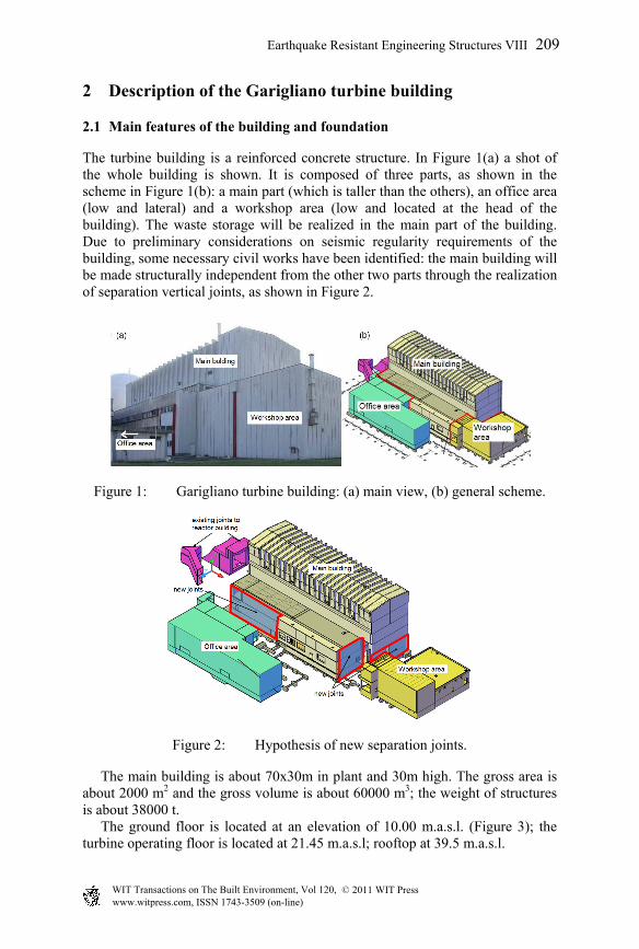
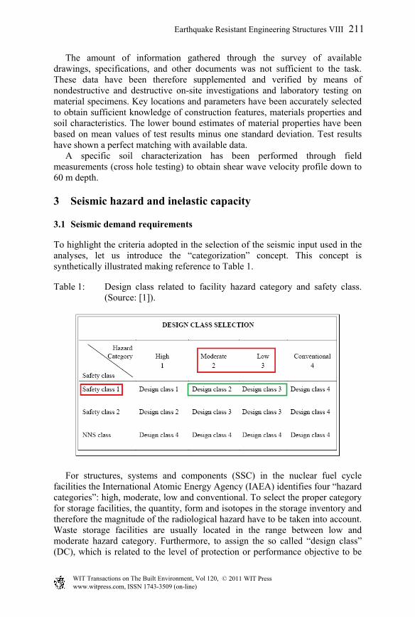
The turbine building is a reinforced concrete structure. In Figure 1(a) a shot of the whole building is shown. It is composed of three parts, as shown in the scheme in Figure 1(b): a main part (which is taller than the others), an office area (low and lateral) and a workshop area (low and located at the head of the building). The waste storage will be realized in the main part of the building. Due to preliminary considerations on seismic regularity requirements of the building, some necessary civil works have been identified: the main building will be made structurally independent from the other two parts through the realization of separation vertical joints, as shown in Figure 2.
Figure 1: Garigliano turbine building: (a) main view, (b) general scheme.
Figure 2: Hypothesis of new separation joints.
The main building is about 70x30m in plant and 30m high. The gross area is about 2000 m2 and the gross volume is about 60000 m3; the weight of structures is about 38000 t. The ground floor is located at an elevation of 10.00 m.a.s.l. (Figure 3); the turbine operating floor is located at 21.45 m.a.s.l; rooftop at 39.5 m.a.s.l.
Earthquake Resistant Engineering Structures VIII 209
www.witpress.com, ISSN 1743-3509 (on-line) WIT Transactions on The Built Environment, Vol 120, © 2011 WIT Press

Figure 3: Building longitudinal section.
The building structure presents a strong discontinuity in stiffness at the turbine operating floor level. Below this floor we find shear walls of great thickness and above this floor we find very slender frames which form great portals 20 m high and 20 m wide. These portals present a certain discontinuity in stiffness: between elevation 21.45 and 29.00 m columns spacing is equal to 5 m; above 29.00 m columns spacing is halved. Support for columns with variable cross sections of the upper part is provided by a longitudinal beam of large cross section. The foundation system is shown in Figure 4: it consists of independent mats laid on the ground at elevations varying between 3 and 5 m. The mats are supported by about 900 weakly reinforced concrete piles having a diameter of 50 cm.
Figure 4: Foundation: (a) mats system, (b) typical foundation section.
2.2 Data collection and supplemental investigations
A significant effort has been dedicated to gathering all the information useful to acquire an adequate knowledge of the physical condition of the structure and of its level of deterioration. In fact, a high level of knowledge is necessary in order to obtain valid estimates of the mechanical parameters of materials required for numerical analysis.
210 Earthquake Resistant Engineering Structures VIII
www.witpress.com, ISSN 1743-3509 (on-line) WIT Transactions on The Built Environment, Vol 120, © 2011 WIT Press
The amount of information gathered through the survey of available drawings, specifications, and other documents was not sufficient to the task. These data have been therefore supplemented and verified by means of nondestructive and destructive on-site investigations and laboratory testing on material specimens. Key locations and parameters have been accurately selected to obtain sufficient knowledge of construction features, materials properties and soil characteristics. The lower bound estimates of material properties have been based on mean values of test results minus one standard deviation. Test results have shown a perfect matching with available data. A specific soil characterization has been performed through field measurements (cross hole testing) to obtain shear wave velocity profile down to 60 m depth.
3 Seismic hazard and inelastic capacity
3.1 Seismic demand requirements
To highlight the criteria adopted in the selection of the seismic input used in the analyses, let us introduce the “categorization” concept. This concept is synthetically illustrated making reference to Table 1.
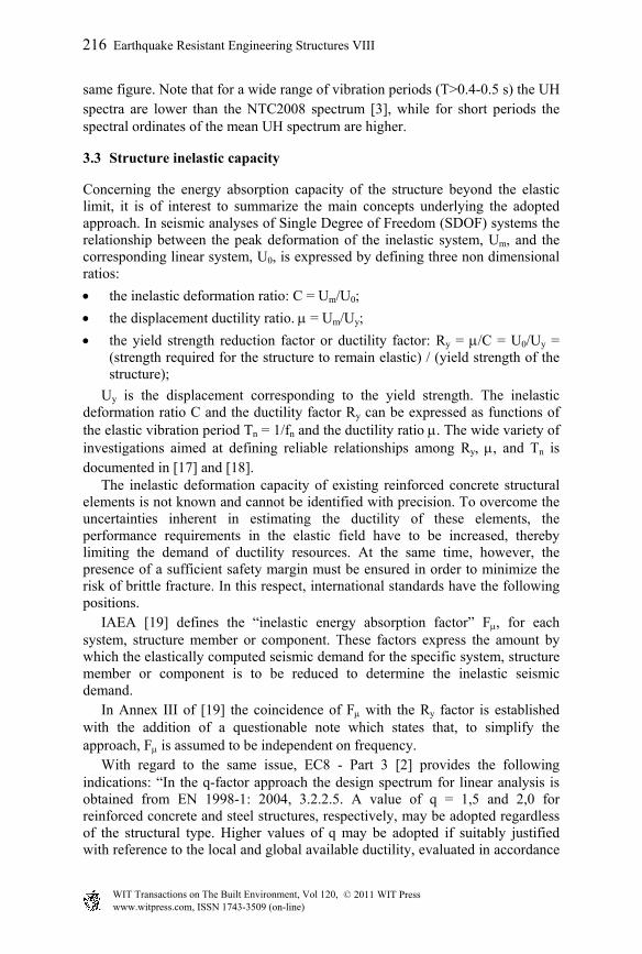
Table 1: Design class related to facility hazard category and safety class. (Source: [1]).
For structures, systems and components (SSC) in the nuclear fuel cycle facilities the International Atomic Energy Agency (IAEA) identifies four “hazard categories”: high, moderate, low and conventional. To select the proper category for storage facilities, the quantity, form and isotopes in the storage inventory and therefore the magnitude of the radiological hazard have to be taken into account. Waste storage facilities are usually located in the range between low and moderate hazard category. Furthermore, to assign the so called “design class” (DC), which is related to the level of protection or performance objective to be
Earthquake Resistant Engineering Structures VIII 211
www.witpress.com, ISSN 1743-3509 (on-line) WIT Transactions on The Built Environment, Vol 120, © 2011 WIT Press

ensured, the importance of the SSC under design in providing protection against radiation has to be considered. Since structural integrity has a dominant importance to contain radiation, safety class 1 is generally assigned to civil structures. It follows that DC 2 or DC 3 could be both appropriate for a radioactive temporary waste storage facility. The design classes can be briefly described as follows: DC 1 ensures the level of protection used for NPP; DC 2 ensures an intermediate level of protection (above building code criteria for essential facilities and below NPP criteria); DC 3 ensures the level of protection used in the building code for essential facilities; DC 4 ensures the level of protection used in building code for conventional facilities. DC 2 has been considered appropriate for safety assessment in the present work. Levels of protection (performance objectives) are defined by associating different threshold limit states (LS) of the structure to earthquake exceedance probabilities. According to EC8 - Part 3 [2], for the protection of ordinary buildings, the approach to be adopted is as follows: LS of Damage Limitation (DL) associated with exceedance probability of 20% in the nominal design life; LS of Significant Damage (SD) associated with exceedance probability of 10% in the nominal design life; LS of Near Collapse (NC) associated with exceedance probability of 2% in the nominal design life. A comparative prospect of limit states as defined in EC8, Italian Code NTC 2008 [3] and FEMA 356 [4] is shown in Table 2.
Table 2: Performance objectives.
OP Operational Performance
IO Immediate Occupancy
LS Life Safety
CP Collapse Prevention FEMA 356 EC8 NTC 2008DL Damage Limitation OP SLO
SD Significant Damage IO SLD
NC Near Collapse LS SD SLV
SLO Stato Limite di Operatività CP NC SLC
SLD Stato Limite di Danno
SLV Stato Limite di Salvaguardia della Vita
SLC Stato Limite di Collasso
Comparison
DLEC8
NTC 2008
FEMA 356
According to NTC 2008 the appropriate levels of protection for essential non nuclear facilities are considered to be achieved by selecting exceedance probabilities (PVR) and return periods (RP) indicated in Table 3 for nominal design life Vn equal to 25 and 50 years. For the temporary waste storage facility of Garigliano NPP Vn = 25 yr. has been chosen. Therefore, to comply with DC 2 criteria, the performance objectives adopted for this facility are as follows: the performance objective SLD has to be ensured under the earthquake with
return period RP = 500 yr. (see arrows in Table 3); the performance objective SLV has to be ensured under the earthquake with
return period RP = 1000 yr.
212 Earthquake Resistant Engineering Structures VIII
www.witpress.com, ISSN 1743-3509 (on-line) WIT Transactions on The Built Environment, Vol 120, © 2011 WIT Press

Table 3: Performance objectives and return periods (NTC 2008).
Cu=2 Cu=2
Vn=25 yr Vn=50 yr
Vr=50 yr Vr=100 yr
performance objective
PVR (exceedance probability)
performance objective
PVR (exceedance probability)
SLO 64% 48 yr SLO 64% 96 yr
SLD 53% 66 yr SLD 53% 132 yr
SLV 10% 487.5 yr SLV 10% 975 yr
SLC 5% 987.5 yr SLC 5% 1975 yr
coefficient of importance
NTC 2008
coefficient of importance
nominal design life
reference design life
nominal design life
reference design life
RP (return period) RP (return period)
SLD in NTC 2008 is equivalent to the EC8 Damage Limitation (DL). The structure is only slightly damaged, with structural elements prevented from significant yielding and retaining their strength and stiffness properties. Non-structural components, such as partitions and infills, may show distributed cracking, but the damage could be economically repaired. Permanent drifts are negligible. The structure does not need any repair measures. SLV in NTC 2008 is equivalent to the EC8 Significant Damage (SD). The structure is significantly damaged, with some residual lateral strength and stiffness, and vertical elements are capable of sustaining vertical loads. Non-structural components are damaged, although partitions and infill panels have not failed out-of-plane. Moderate permanent drifts are present. The structure can sustain after-shocks of moderate intensity. The structure is likely to be uneconomic to repair.
3.2 Hazard evaluation: site response spectrum
The reference response spectrum on free field conditions at the site has been evaluated through probabilistic seismic hazard analysis (PSHA). The results can be expressed either as “hazard curves” (annual probability of exceedance vs. ground motion parameter) for different spectral ordinates or, equivalently, as uniform hazard (UH) response spectra, which indicate, for a fixed annual probability of exceedance, the value of the ground motion parameter vs. the structural period. In a PSHA, the uncertainties are generally divided into aleatory uncertainties, related to the unpredictable nature of future earthquakes and, typically, included in the standard error of the ground motion predictive equations (GMPEs), and epistemic uncertainties, stemming from incomplete data and imperfect knowledge regarding the earthquake process. The latter are accounted for by adopting different models in a logic tree approach. Each branch of this tree represents a different choice regarding a specific step of the analysis, and a normalized weight is assigned to it. The final result derives from the combination of the hazard curves calculated by following all the possible branches of the logic tree. For the region at study, different representations of the seismogenic zones that govern hazard are possible. The first representation is the seismotectonic model
Earthquake Resistant Engineering Structures VIII 213
www.witpress.com, ISSN 1743-3509 (on-line) WIT Transactions on The Built Environment, Vol 120, © 2011 WIT Press

ZS9 [5], basis of the hazard zonation included in the present Italian seismic code [3]. For this model, the parameters of the Gutenberg Richter relationship have been computed by fitting the earthquake rates derived from the Italian earthquake catalogue CPTI04 (http://emidius.mi.ingv.it/CPTI). The slope b of the relationship has been derived both for each source and at a regional level. The second representation is the so-called “smoothed seismicity”, [6] in which each point of a grid is considered as a possible source and the rates are computed only on the basis of the earthquake catalogue. To this end, the results obtained in the DPC-INGV national project S2 (http://nuovoprogettoesse2.stru.polimi.it/, 2007-2009) have been used. The third option is a fault model. The basic reference for the description of seismically active faults was taken to be the database of the Italian seismic sources DISS3 (http://diss.rm.ingv.it/diss/). Moreover, since the Italian earthquake catalogue CPTI04 includes an event of magnitude 6.6 (occurred in 1349) at a distance of about 30 km from the NPP, the information derived from the DBMI04 (http://emidius.mi.ingv.it/DBMI04/) the previous version of DISS3.0.4 and the study by [7] have been combined. Thus, a new source for the 1349 earthquake has been defined (red rectangle in Figure 5). All the faults, shown in Figure 5, are considered capable of exhibiting a “characteristic earthquake” [8], modelled through a Brownian Passage Time (BPT) distribution [9], [10]. A background seismicity (for magnitudes Mw≤6.5) has been associated to the ZS9 sources (green polygons in Figure 5).
Figure 5: Seismotectonic context of the region at study: SSZs of the ZS9 model (green), faults of DISS3.1.0 (in blue). The zoom on the rhs displays the different reconstructions of the macroseismic source of the 1349 event, according to DBMI04 (green rectangle), DISS3.0.4 (black) and Galli e Naso (2009) (blue line), as well as the source adopted in this analysis (red). (See online for colour version.)
The attenuation equations (GMPEs) adopted for the analysis are: Boore and Atkinson [11], BA08, Cauzzi and Faccioli [12], CF08, Bindi et al. [13], BIEA09 and Akkar and Bommer [14], AB10. Since the models used different definition of the predicted motions, the conversion factors proposed by [15] have been
214 Earthquake Resistant Engineering Structures VIII
www.witpress.com, ISSN 1743-3509 (on-line) WIT Transactions on The Built Environment, Vol 120, © 2011 WIT Press

applied and the results are given in terms of geometric mean of the horizontal components. As mentioned, the different choices regarding the seismotectonic context, the hazard parameters and the GMPEs have been combined into a logic tree (shown in Figure 6). All the hazard computations were carried out with CRISIS2008 code an enlarged version of the well-known CRISIS2007 code ( [16]). Context Mmax and param. GMPE Weights
Figure 6: Logic tree adopted in the PSHA. The weights associated with each branch are shown in red. (See online for colour version.)
The resulting UH response spectrum (soil type C, Vs30=266 m/s) for a return period (RP) of 975 yr. is shown in Figure 7 in terms of mean and band of dispersion (dotted curves). For the sake of comparison the elastic response spectrum provided by the Italian seismic code NTC2008 is also displayed in the
0 0.5 1 1.5 20
0.2
0.4
0.6
0.8
1
T [s]
SA [g
]
NTC 2008UH spectrum - RP=975 yr.
Figure 7: Comparison between the mean UH spectrum for RP=975 yr. And band of dispersion resulting from the analysis and the elastic response spectrum from NTC 2008.
Earthquake Resistant Engineering Structures VIII 215
www.witpress.com, ISSN 1743-3509 (on-line) WIT Transactions on The Built Environment, Vol 120, © 2011 WIT Press
same figure. Note that for a wide range of vibration periods (T>0.4-0.5 s) the UH spectra are lower than the NTC2008 spectrum [3], while for short periods the spectral ordinates of the mean UH spectrum are higher.
3.3 Structure inelastic capacity
Concerning the energy absorption capacity of the structure beyond the elastic limit, it is of interest to summarize the main concepts underlying the adopted approach. In seismic analyses of Single Degree of Freedom (SDOF) systems the relationship between the peak deformation of the inelastic system, Um, and the corresponding linear system, U0, is expressed by defining three non dimensional ratios:
the inelastic deformation ratio: C = Um/U0;
the displacement ductility ratio. = Um/Uy;
the yield strength reduction factor or ductility factor: Ry = /C = U0/Uy = (strength required for the structure to remain elastic) / (yield strength of the structure);
Uy is the displacement corresponding to the yield strength. The inelastic deformation ratio C and the ductility factor Ry can be expressed as functions of the elastic vibration period Tn = 1/fn and the ductility ratio . The wide variety of investigations aimed at defining reliable relationships among Ry, , and Tn is documented in [17] and [18]. The inelastic deformation capacity of existing reinforced concrete structural elements is not known and cannot be identified with precision. To overcome the uncertainties inherent in estimating the ductility of these elements, the performance requirements in the elastic field have to be increased, thereby limiting the demand of ductility resources. At the same time, however, the presence of a sufficient safety margin must be ensured in order to minimize the risk of brittle fracture. In this respect, international standards have the following positions. IAEA [19] defines the “inelastic energy absorption factor” F, for each system, structure member or component. These factors express the amount by which the elastically computed seismic demand for the specific system, structure member or component is to be reduced to determine the inelastic seismic demand. In Annex III of [19] the coincidence of F with the Ry factor is established with the addition of a questionable note which states that, to simplify the approach, F is assumed to be independent on frequency. With regard to the same issue, EC8 - Part 3 [2] provides the following indications: “In the q-factor approach the design spectrum for linear analysis is obtained from EN 1998-1: 2004, 3.2.2.5. A value of q = 1,5 and 2,0 for reinforced concrete and steel structures, respectively, may be adopted regardless of the structural type. Higher values of q may be adopted if suitably justified with reference to the local and global available ductility, evaluated in accordance
216 Earthquake Resistant Engineering Structures VIII
www.witpress.com, ISSN 1743-3509 (on-line) WIT Transactions on The Built Environment, Vol 120, © 2011 WIT Press

with the relevant provisions of EN 1998-1: 2004”. The q factor even in this case is equivalent to the above defined reduction factor Ry and is considered independent of frequency. The q-factor approach is also adopted by the Italian code NTC 2008 [3]. The U.S. Electric Power Research Institute (EPRI) [20] defines the so called “ductility reduction factor”, k = 1/Ry . The reduced earthquake forces are obtained by multiplying the elastically calculated forces by the reduction factor, k. EPRI suggests: “for all but the most brittle failure modes, one can very conservatively choose k = 0.8”, which means Ry = 1.25. In this work, the assessment of SLV performance objective has been carried out by means of linear analyses. The inelastic deformation capacity of reinforced concrete structural elements has been taken into account by considering the dependency of Ry on frequency and by conservatively assuming the Ry--Tn Newmark’s relationship with = 1.5. It follows that, in the range of frequencies between 2 and 8 Hz, Ry is equal to 1.4.
4 Seismic response analysis
4.1 Finite element model
The finite element model adopted for the structure is shown in Figure 8. A portion of soil and the piles have been explicitly represented in the model to reproduce the effects of soil structure interaction. The volume of soil considered in the model has no mass, is sufficiently broad as to make irrelevant the influence on response of the boundary constraints and takes into account the soil layering profile of the site. The model of the superstructures is made of beam, plates and massive finite elements and reproduces in great detail the geometry and stiffness of all structural components. In addition to masses resulting from dead loads, the mass of auxiliary systems (i.e. cranes), radioactive material and containers to be stored is properly distributed at different levels. The total weight due to these overloads is approximately 10.000 t; therefore the total mass of the model is about 38.000+10.000 = 48.000 t.
4.2 Dynamic and seismic response of the structure
The earthquake response of the turbine building has been evaluated through linear dynamic and response spectrum analyses. Soil-structure interaction (SSI) causes an increase in the fundamental natural period of the structure and in damping values with respect to the theoretical assumption of rigid soil. As known, an increased period due to SSI may lead, as a result of soil or seismological factors, to higher response of the superstructure [21]. As far as the change in damping is concerned, it is the result of energy dissipation in the soil due to radiation and material damping. In the modal analysis procedure, SSI mainly affects the fundamental vibration modes only, i.e. modes with higher participation factors, whereas the higher
Earthquake Resistant Engineering Structures VIII 217
www.witpress.com, ISSN 1743-3509 (on-line) WIT Transactions on The Built Environment, Vol 120, © 2011 WIT Press

Figure 8: Finite element model of the turbine building – different views.
modes are relatively unaffected. SSI effects have been therefore taken into account in the analyses by adopting empirical findings [22] and by properly modifying the elastic response spectrum ordinates according to the criteria described in Appendix E of [23]. The expected shear modulus at small strain levels for the soils beneath the foundations have been estimated from shear wave velocity profile obtained by cross-hole testing. The shear modulus value at large strain levels, compatible with the adopted seismic excitation, has been determined in accordance with [4]. The fundamental modes of the building involve mainly the large portal above 21.45 m elevation. The fundamental transverse mode (Figure 9, left) presents a flexional shape both in horizontal and vertical planes, with maximum deflections located in the middle vertical plane of the building; the mode is associated with a frequency of 2.3 Hz and involves about 80% of the total mass. The fundamental longitudinal mode (Figure 9, right) presents local peaks of deformation in the head walls; it is associated with a frequency of 2.5 Hz and involves up to 95% of the total mass. The first fundamental vertical mode is at 4.3 Hz and involves about 75% of total mass. As previously mentioned, the temporary waste storage facility should ensure the performance objective SLD against the earthquake with RP = 475 yr and the performance objective SLV against the earthquake with RP = 1000 yr.
218 Earthquake Resistant Engineering Structures VIII
www.witpress.com, ISSN 1743-3509 (on-line) WIT Transactions on The Built Environment, Vol 120, © 2011 WIT Press
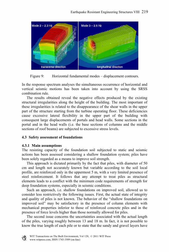
Figure 9: Horizontal fundamental modes – displacement contours.
In the response spectrum analyses the simultaneous occurrence of horizontal and vertical seismic motions has been taken into account by using the SRSS combination rule. The results obtained reveal the negative effects produced by the existing structural irregularities along the height of the building. The most important of these irregularities is related to the disappearance of the shear walls in the upper part of the structure starting from the turbine operating floor. These deficiencies cause excessive lateral flexibility in the upper part of the building with consequent large displacements of portals and head walls. Some sections in the portal and in the head walls (i.e. the base sections of columns and the middle sections of roof beams) are subjected to excessive stress levels.
4.3 Safety assessment of foundations
4.3.1 Main assumptions The resisting capacity of the foundation soil subjected to static and seismic actions has been assessed considering a shallow foundation system; piles have been solely regarded as a means to improve soil strength. This approach is dictated primarily by the fact that piles, with diameter of 50 cm and length not accurately known but variable according to the soil local profile, are reinforced only in the uppermost 5 m, with a very limited presence of steel reinforcement. It follows that any attempt to treat piles as structural elements leads to a conflict with the minimum code requirements of strength for deep foundation systems, especially in seismic conditions. Such an approach, i.e. shallow foundations on improved soil, allowed us to consider less restrictively the following issues. First, the actual state of integrity and quality of piles is not known. The behavior of the “shallow foundations on improved soil” may be satisfactory in the presence of column elements with mechanical properties inferior to those of reinforced concrete piles and in the presence of force levels higher than those normally allowed for piles. The second issue concerns the uncertainties associated with the actual length of the piles, varying roughly between 13 and 18 m. In fact, it is not possible to know the true length of each pile or to state that the sandy and gravel layers have
Earthquake Resistant Engineering Structures VIII 219
www.witpress.com, ISSN 1743-3509 (on-line) WIT Transactions on The Built Environment, Vol 120, © 2011 WIT Press
been actually reached by all piles, or to exclude the presence of lenses or layers of silty-clay below the base of piles clamped in the sandy and gravel layers. Even from this point of view, the behavior of the “shallow foundations on treated soil” may result satisfactory in situations where, locally, the minimum safety requirements for bearing capacity of foundation piles cannot be met.
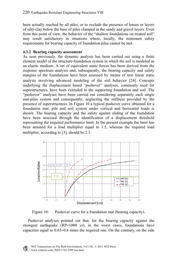
4.3.2 Bearing capacity assessment As seen previously, the dynamic analysis has been carried out using a finite element model of the structure-foundation system in which the soil is modeled as an elastic medium. A set of equivalent static forces has been derived from the response spectrum analysis and, subsequently, the bearing capacity and safety margins of the foundations have been assessed by means of non linear static analysis involving advanced modeling of the soil behavior [24]. Concepts underlying the displacement based “pushover” analyses, commonly used for superstructures, have been extended to the supporting foundation and soil. The “pushover” analyses have been carried out considering separately each single mat-piles system and consequently, neglecting the stiffness provided by the presence of superstructures. In Figure 10 a typical pushover curve obtained for a foundation mat, pile and soil system under vertical and horizontal loads is shown. The bearing capacity and the safety against sliding of the foundation have been assessed through the identification of a displacement threshold representing the required performance limit. In the present example the limit has been attained for a load multiplier equal to 1.5, whereas the required load multiplier, according to [3], should be 2.3.
Figure 10: Pushover curve for a foundation mat (bearing capacity).
Pushover analyses pointed out that, for the bearing capacity against the strongest earthquake (RP=1000 yr), in the worst cases, foundations have capacities equal to 0.650.8 times the required one. On the contrary, on the side
220 Earthquake Resistant Engineering Structures VIII
www.witpress.com, ISSN 1743-3509 (on-line) WIT Transactions on The Built Environment, Vol 120, © 2011 WIT Press
of the sliding capacity assessment, the analyses have shown sufficient safety margins.
5 Planned retrofitting actions
According to FEMA [4, 25] four main retrofitting strategies can be conceived: (a) local strengthening of components; (b) removal of existing irregularities; (c) global structural stiffening; (d) global structural strengthening. The turbine building upgrading requires the simultaneous use of all these strategies. The local strengthening will increase the capacity of single structural elements without affecting the overall response of the structure. The removal of existing irregularities will reduce the demand predicted by the analysis. Construction of new braced frames or shear walls within the structure is an effective measure for adding stiffness in places where it is lacking. The main planned actions for seismic rehabilitation of the Garigliano turbine building consist of: (1) the strengthening of the upper part of the building starting from the turbine operating floor, and (2) the upgrading of foundations. To attain the first aim, braced frames or shear walls in cross direction will be built. Furthermore, beams to reduce the flexional deformability of the head wall will be added. It is worth noting that these new structures should not disturb the normal radioactive waste handling in the storage. Local strengthening actions are limited to few columns at the 21.45 m elevation that will be strengthened by means of steel jacketing. A further local strengthening will be designed for the existing steel connections between the turbine pedestal and the main body of the building at the 21.45 m elevation. On the foundation side, the upgrading actions should improve both the uniformity of the distribution onto the soil of the actions coming from the superstructure and the soil bearing capacity. To comply with the first aim, new stiffened slabs will be poured at ground level; these new structures will have the twofold effect of connecting the existing mats and of providing the proper increment of bending stiffness. To achieve the second goal, grouting operations in the soil will be carried out.
6 Conclusions
In the near future the turbine building of the Garigliano NPP could be used as a temporary radioactive waste storage facility. In this paper the method and design criteria adopted to achieve a reliable estimate of the building capacity to withstand the design earthquake have been briefly described. Numerical safety assessment and critical issues in the superstructure and in the foundations are described. An overview of strengthening interventions to be implemented to achieve the required level of seismic safety has been also provided. The seismic safety assessment of the turbine building is clearly a very significant component of the complex evaluation of costs and benefits associated with a safe extension of the structure life. In this regard, it is worth to bear in mind that the resistance against earthquake of old reinforced concrete structures
Earthquake Resistant Engineering Structures VIII 221
www.witpress.com, ISSN 1743-3509 (on-line) WIT Transactions on The Built Environment, Vol 120, © 2011 WIT Press
strongly depends on the chemical and physical effects of aging, the careful conception of construction details and the quality of execution. The information that can be retrieved in regard to these aspects has a mostly qualitative nature. It is therefore difficult to translate it into numerical parameters even of the most appropriate and accurate mathematical model. This observation inevitably suggests the belief that even the most extensive investigations about construction materials and the highest level of accuracy and completeness of the mathematical simulation should in any case be accompanied by a mature and expert engineering judgment.
References
[1] IAEA-TECDOC-1250, Seismic design considerations of nuclear cycle facilities, October 2011.
[2] EN 1998-3, Eurocode 8 (EC8), Design of structure for earthquake resistance. Part 3: Assessment and retrofitting of buildings, August 2005.
[3] D.M. 14 gennaio 2008, Norme tecniche per le costruzioni (NTC 2008), 2008.
[4] FEMA 356, Prestandard and commentary for the seismic rehabilitation of building, November 2000
[5] Gruppo di Lavoro, 2004a per la redazione della mappa di pericolosità sismica. INGV, Final Report, (http://esse1.mi.ingv.it) with Appendices.
[6] Frankel, A., 1995. Mapping seismic hazard in the central and eastern United States, Seism. Res. Lett. 66, 8–21.
[7] Galli, P.A., Naso, J.A., Unmasking the 1349 earthquake source (southern Italy): paleoseismological and archaeoseismological indications from the Aquae Iuliae fault, Journal of Structural Geology, 31, 128–149, 2009.
[8] Youngs, R.R., Coppersmith, K.J. Implications of fault slip rates and earthquake recurrence models to probabilistic seismic hazard estimates, Bulletin of the Seismological Society of America, Vol. 75, No. 4, pp. 939–964, 1985
[9] Matthews, M.V., Ellsworth, W.L., Reasenberg, P.A. A Brownian Model for Recurrent Earthquakes, Bulletin of the Seismological Society of America, Vol. 92, No. 6, pp. 2233–2250, 2002
[10] Peruzza, L., Pace, B., Cavallini, F. Error propagation in time-dependent probability of occurrence for characteristic earthquakes in Italy, Journal of Seismology, DOI 10.1007/s10950-008-9131-1, 2010.
[11] Boore, D.M., and Atkinson, G.M. Ground-motion prediction equations for the average horizontal component of PGA, PGV, and 5%-damped PSA at spectral periods between 0.01 s and 10.0 s, Earthquake Spectra, 24(1), 99-138, 2008.
[12] Cauzzi, C., and Faccioli, E., Broad band (0.05 s to 20s) prediction equations for displacement response spectra calibrated on a worldwide digital database, Journal of Seismology 12, 453-475, 2008.
[13] Bindi D., Luzi L., Massa M., Pacor F., Horizontal and vertical ground motion prediction equations derived from the Italian Accelerometric
222 Earthquake Resistant Engineering Structures VIII
www.witpress.com, ISSN 1743-3509 (on-line) WIT Transactions on The Built Environment, Vol 120, © 2011 WIT Press
Archive (ITACA). Bulletin of Earthquake Engineering. In press. doi: 10.1007/s10518-009-9130-9, 2009.
[14] Akkar, S., and Bommer, J.J. Empirical equations for the prediction of PGA, PGV and spectral acceleration in Europe, the Mediterranean region and the Middle East. Seismological Research Letters, vol. 81(2) pp. 195-206, 2010.
[15] Beyer K., Bommer J.J., Relationships between Median Values and between Aleatory Variabilities for Different Definitions of the Horizontal Component of Motion, Bulletin of the Seismological Society of America, Vol. 96, No. 4A, pp. 1512–1522, 2006.
[16] Ordaz M., Jara J.M., Singh S.K. Riesgo sísmico y espectros de diseño en el estado de Guerrero. Technical Report, Instituto de Ingenieria, UNAM, Mexico City, 1991.
[17] E. Miranda, V. Bertero, Evaluation of strength reduction factors for earthquake-resistant design, Earthquake Spectra, Vol. 10, No 2, 1994.
[18] A.K. Chopra, R.K. Goel, Capacity-demand-Diagram for estimating seismic deformation of inelastic structures. SDOF systems, Report PEER-1999/0.
[19] IAEA - Safety Reports Series No. 28, Seismic evaluation of existing Nuclear Power Plant, 2003
[20] Electric Power Research Institute (EPRI), A methodology for assessment of Nuclear Power Plant Seismic Margin, EPRI NP-6041, October 1988.
[21] G. Gazetas, Seismic design of foundations and soil-structure interaction, First ECEES, 2-8 September 2006.
[22] J.P. Stewart, J.P. Seed, G.L. Fenves, Seismic soil structure interaction in buildings. II: empirical findings, ASCE Journal of geotechnical engineering, 1999.
[23] FEMA 440, Improvement of nonlinear static seismic analysis procedures, June 2005.
[24] SGI – Studio Geotecnico Italiano - Servizio di valutazione sismica dell’edificio turbina della centrale del Garigliano – Verifica delle fondazioni in condizioni sismiche, SGI Report n. 08073-060RO1E01, November 2010.
[25] FEMA 547 Techniques for the Seismic Rehabilitation of Existing Buildings, October 2006.
Earthquake Resistant Engineering Structures VIII 223
www.witpress.com, ISSN 1743-3509 (on-line) WIT Transactions on The Built Environment, Vol 120, © 2011 WIT Press