gann hydromette rtu 600 · 4 technical specifications - hydromette rtu 600 (1) bnc connection...
TRANSCRIPT

1
GANN HYDROMETTE RTU 600
Operating Instructions

2
All copyrights reserved Reproduction of this manual, also in part, by print, copying or any other procedure is not permitted unless approved in writing by GANN Mess- u. Regeltechnik GmbH.
This manual has been most carefully composed. The manufacturer and/or supplier assumes no liability, however, for possible misprints or errors. Copyright by GANN Mess- u. Regeltechnik GmbH. Stuttgart, Federal Republic of Germany

3
4
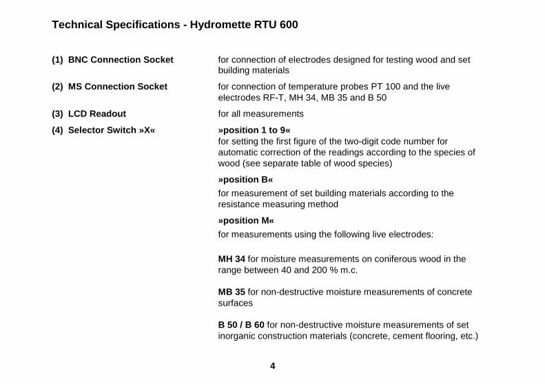
Technical Specifications - Hydromette RTU 600 (1) BNC Connection Socket for connection of electrodes designed for testing wood and set building materials
(2) MS Connection Socket for connection of temperature probes PT 100 and the live electrodes RF-T, MH 34, MB 35 and B 50
(3) LCD Readout for all measurements
(4) Selector Switch »X« »position 1 to 9«
for setting the first figure of the two-digit code number for automatic correction of the readings according to the species of wood (see separate table of wood species)
»position B«
for measurement of set building materials according to the resistance measuring method
»position M«
for measurements using the following live electrodes:
MH 34 for moisture measurements on coniferous wood in the range between 40 and 200 % m.c. MB 35 for non-destructive moisture measurements of concrete surfaces B 50 / B 60 for non-destructive moisture measurements of set inorganic construction materials (concrete, cement flooring, etc.)

5
»position M«
RF-T 28 for air humidity measurements,
RF-T 31 for air humidity measurements,
RF-T 32 for air humidity measurements,
IR 33 for surface temperature measurements with infrared sensor,
»position 200°« for temperature measurements up to 200 °C with elec trodes RF- T 28, RF-T 31, RF-T 32 and temperature probes PT 100,
»position 600°« for temperature measurements up to 600 °C using pro bes PT
100,
»position Batt« for battery check.
(5) Selector Switch »Y« for setting second figure of the two-digit code for automatic correction of wood moisture readings
(6) Selector Switch for setting wood temperature for automatic compensation of its effect on wood moisture readings.
(7) Measuring Key ON/OFF

6
Battery Check Set selector switch (4) to position »Batt« and press measuring key (7). The reading displayed should be higher than 7.5 digits. If it is 7.5 digits or lower, the battery is exhausted and should be replaced or recharged if a rechargeable battery is being used. The cover of the battery compartment can be lifted by means of a coin inserted into the slot. It is recommendable to replace or recharge the battery once the reading of the battery check is below 8 digits. Power Source The meter is fitted, as standard, with a 9 V dry battery IEC 6 F 22 or IEC 6 LF 22. It is recommended to use alkali-mangan batteries. A rechargeable nickel-cadmium battery can be fitted (optional accessory). It can be recharged from any A.C. lighting supply socket by means of the charging unit supplied with this special battery. Calibration The meter is fitted with an electronic setting device, making manual calibration or adjustment unnecessary.
7
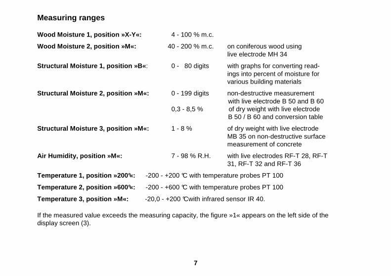
Measuring ranges Wood Moisture 1, position »X-Y«: 4 - 100 % m.c.
Wood Moisture 2, position »M«: 40 - 200 % m.c. on coniferous wood using live electrode MH 34
Structural Moisture 1, position »B« : 0 - 80 digits with graphs for converting read- ings into percent of moisture for various building materials
Structural Moisture 2, position »M«: 0 - 199 digits non-destructive measurement with live electrode B 50 and B 60 0,3 - 8,5 % of dry weight with live electrode B 50 / B 60 and conversion table
Structural Moisture 3, position »M«: 1 - 8 % of dry weight with live electrode MB 35 on non-destructive surface measurement of concrete
Air Humidity, position »M«: 7 - 98 % R.H. with live electrodes RF-T 28, RF-T 31, RF-T 32 and RF-T 36
Temperature 1, position »200°«: -200 - +200 °C with temperature probes PT 100
Temperature 2, position »600°«: -200 - +600 °C with temperature probes PT 100
Temperature 3, position »M«: -20,0 - +200 °Cwith infrared sensor IR 40. If the measured value exceeds the measuring capacity, the figure »1« appears on the left side of the display screen (3).
8
Dimensions Plastic casing: Length 180 mm x Width 115 mm x Height 53 mm. Weight: about 400 g without accessory. Admissible ambient temperatures Storage: 5 to 40 °C; temporarily -10 to 60 °C Operation: 0 to 50 °C, short term -10 to 60 °C not c ondensing The meter including accessory must not be stored or used in aggressive air or air contaminated by solvents. General Remark The instructions for use of the meter and of the electrodes should be carefully observed to avoid measuring errors which may occur when trying to simplify the measuring procedure. Warning Make sure in any case prior to drilling holes for measuring probes or before driving electrode pins into walls, ceilings or floors that this happens away from power lines, water pipings or other supply pipes.

9
Standard and Optional Accessory
Drive-in Electrode M 20 (Ref. No. 3300)
for surface and subsurface measurements on wood up to 50 mm thick. Also for testing chipboard, fibreboard and set construction materials (plaster, mortar, etc.), with measuring pins
- 16 mm long (Ref. No. 4610), penetration depth 10 mm - 23 mm long (Ref. No. 4620), penetration depth 17 mm.
Surface Measuring Caps M 20-OF 15 (Ref. No. 4315)
for moisture measurements on surfaces (e.g. veneer, con- crete) without damaging the material (only in conjunction with electrode M 20).
10
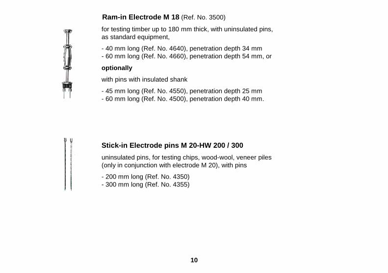
Ram-in Electrode M 18 (Ref. No. 3500)
for testing timber up to 180 mm thick, with uninsulated pins, as standard equipment,
- 40 mm long (Ref. No. 4640), penetration depth 34 mm - 60 mm long (Ref. No. 4660), penetration depth 54 mm, or
optionally
with pins with insulated shank
- 45 mm long (Ref. No. 4550), penetration depth 25 mm - 60 mm long (Ref. No. 4500), penetration depth 40 mm.
Stick-in Electrode pins M 20-HW 200 / 300
uninsulated pins, for testing chips, wood-wool, veneer piles (only in conjunction with electrode M 20), with pins
- 200 mm long (Ref. No. 4350) - 300 mm long (Ref. No. 4355)

11
Brush Electrodes M 25 (Ref. No. 3740) made of stainless steel, for moisture measurements of hard and soft building materials without contact paste, measuring depth up to 100 mm.
Stick-in Electrodes M 6 (Ref. No. 3700)
for testing hard building materials, using contact paste and pre-drilled holes, with pins
- 23 mm long (Ref. No. 4620) - 40 mm long (Ref. No. 4640) - 60 mm long (Ref. No. 4660)

12
Flat Electrodes M6-Bi 200 / 300
for measurements in insulating material of cement flooring through the edge joint (with insulated shank), only for use in conjunction with the handles of the electrodes M 6.
- size 10 x 0.8 x 200 mm (Ref. No. 3702) - size 10 x 0.8 x 300 mm (Ref. No. 3703) Stick-in Electrodes M 6 – 150 / 250 especially thin and uninsulated pins for testing building and insulating materials through the joint or cross joint of tiles
Size 150 x 3 mm Ø (Ref. No. 3706)
Size 250 x 2 mm Ø (Ref. No. 3707) (for use with M 6 and M 20 electrodes)

13
Deep Electrodes M 21-100 / 250
for deep measurements in set building materials, in conjunction with contact paste and pre-drilled holes
- 100 mm long (Ref. No. 3200) - 250 mm long (Ref. No. 3250).
Contact Paste (Ref. No. 5400)
to ensure good contact between electrode pins and tested building materials. For moisture measurements in hard building materials (cement flooring, concrete, etc.) with electrodes M 6 and M 21.
Live electrode MH 34 (Ref.No. 3350)
with integrated measuring circuit, for measurement of high moisture contents in coniferous wood, specially in case of water-borne storage and pre-sorting of freshly cut timber for kiln drying.
Measuring range : 40 to 200 % m.c.

14
Active Electrode B 50 (Ref. No. 3750) with integrated measuring circuit, designed for non- destructive location of moisture concentration in con- struction materials and moisture distribution in walls, ceilings and floors. It works according to a patented measuring procedure and generates a concentrated high frequency field with substantial penetration depth.
Measuring range: 0 to 199 digits, classification by table. 0.3 to 8.5 % of dry weight, conver- sion by table according to material tested. 0.3 to 6.5 % CM, conversion by table according to material tested.
15
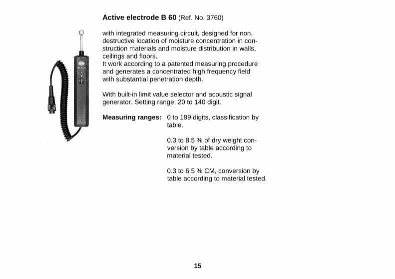
Active electrode B 60 (Ref. No. 3760) with integrated measuring circuit, designed for non. destructive location of moisture concentration in con- struction materials and moisture distribution in walls, ceilings and floors. It work according to a patented measuring procedure and generates a concentrated high frequency field with substantial penetration depth. With built-in limit value selector and acoustic signal generator. Setting range: 20 to 140 digit. Measuring ranges: 0 to 199 digits, classification by table. 0.3 to 8.5 % of dry weight con- version by table according to material tested. 0.3 to 6.5 % CM, conversion by table according to material tested.
16
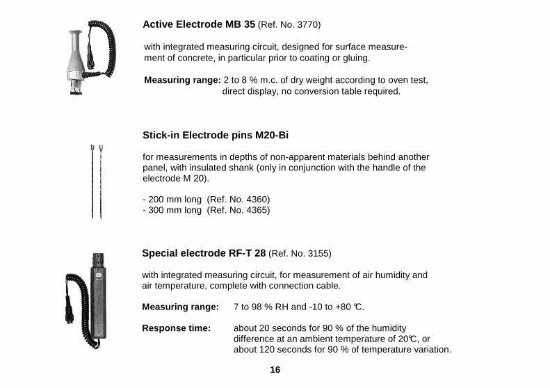
Active Electrode MB 35 (Ref. No. 3770) with integrated measuring circuit, designed for surface measure- ment of concrete, in particular prior to coating or gluing. Measuring range: 2 to 8 % m.c. of dry weight according to oven test, direct display, no conversion table required.
Stick-in Electrode pins M20-Bi
for measurements in depths of non-apparent materials behind another panel, with insulated shank (only in conjunction with the handle of the electrode M 20). - 200 mm long (Ref. No. 4360) - 300 mm long (Ref. No. 4365)
Special electrode RF-T 28 (Ref. No. 3155)
with integrated measuring circuit, for measurement of air humidity and air temperature, complete with connection cable.
Measuring range: 7 to 98 % RH and -10 to +80 °C.
Response time: about 20 seconds for 90 % of the humidity difference at an ambient temperature of 20°C, or about 120 seconds for 90 % of temperature variation.

17
Filter Cap (Ref. No. 3156) of sintered bronze for use with electrode RF-T 28 in dust laden air or at high air speed
Special electrode RF-T 36 (Ref. No. 3136) for measurement of air humidity and air temperature, water activity value or equilibrium moisture in rooms, warehouses or solid substances (e.g. concrete, subflooring, masonry, etc.)
Measuring Range : 5 to 98 % R.H. -5 to +60 °C Dimensions: 82 x 80 x 55 mm Sensor tube: length 55 mm, dia. 12 mm
Special electrode RF-T 31 for measurement of atmospheric moisture, water activity value or equilibrium moisture in bulk materials and solid substances, e.g. brickwork and other building materials. Measuring range : 7 to 98 % R.H. -10 to +80 °C. Sensor tube: dia. 10 mm Sintered filter tip 32 mm long.
Insertion length 250 mm (Ref. No. 3131) Insertion length 500 mm (Ref. No. 3132)

18
Bore hole adapter with closing plug, for use with plug-in sensor RF-T 31 for equilibrium moisture measurement in brick-work or building materials. For bore holes up to 150 mm in depth (Ref. No. 5615) For bore holes up to 250 mm in depth (Ref. No. 5625) For bore holes up to 500 mm in depth (Ref. No. 5650) Blade Sensor RF-T 32 for measurement of atmospheric humidity, water activity value and equilibrium moisture in paper, leather, textile and tobacco stores, etc. Measuring range: 7 to 98 % R.H. -10 to +80 °C. Flat elliptical probe abt. 10 x 4 mm. Insertion length 250 mm (Ref. No. 3133) Insertion length 500 mm (Ref. No. 3134)

19
Sensor Check
Test and calibrating box for
Probe RF-T 28 (Ref. No. 5728) Probe RF-T 31 (Ref. No. 5731) Probe RF-T 32 (Ref. No. 5732)
Test and Calibrating Fluid
for checking and recalibrating all electrodes type RF-T. Package of 5 ampoules of test fluid for sensor check, including absorbing fleece, sufficient for 5 tests or recalibrations.
SCF 30 for the range of 10 to 50 % R.H. (Ref. No. 5753) SCF 70 for the range of 50 to 90 % R.H. (Ref. No. 5757)
SCF 90 for the range of 80 to 98 % R.H. (Ref. No. 5759)

20
Infrared Surface Temperature Sensor IR 40 (Ref. No. 3150)
Contactless temperature measurement from -20 to +199.9 °C, resolution 0.1 °C, emissivity permanently set at 9 5 %, ratio of measured area to distance 2.5:1 (Ø 45 mm at a distance of 100 mm), sensor length 185 mm x 36 x 33 mm, coiled cable 320/1200 mm.
An ideal sensor for detection of heat bridges, determination of the dew point temperature, measurement of live, moving or vi- brating components as well as measurement of components with low heat capacity, e.g. wood, glass, insulating materials, etc.
Matt-black stickers IR 30/E 95 (Ref. No. 5833)
Measurement spot 30 mm ø, emissivity 95 %, e.g. for meas- urement of metallic surfaces.
21
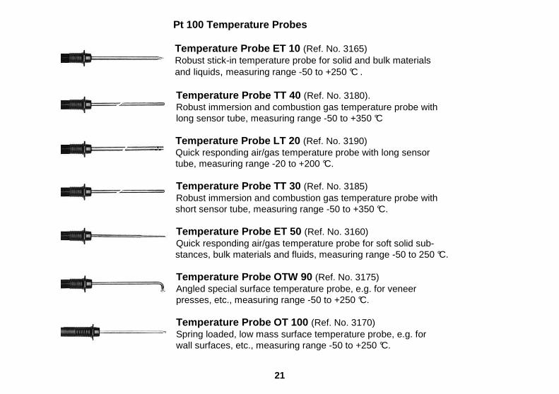
Pt 100 Temperature Probes
Temperature Probe ET 10 (Ref. No. 3165) Robust stick-in temperature probe for solid and bulk materials
and liquids, measuring range -50 to +250 °C .
Temperature Probe TT 40 (Ref. No. 3180). Robust immersion and combustion gas temperature probe with
long sensor tube, measuring range -50 to +350 °C
Temperature Probe LT 20 (Ref. No. 3190) Quick responding air/gas temperature probe with long sensor tube, measuring range -20 to +200 °C.
Temperature Probe TT 30 (Ref. No. 3185) Robust immersion and combustion gas temperature probe with
short sensor tube, measuring range -50 to +350 °C.
Temperature Probe ET 50 (Ref. No. 3160) Quick responding air/gas temperature probe for soft solid sub- stances, bulk materials and fluids, measuring range -50 to 250 °C.
Temperature Probe OTW 90 (Ref. No. 3175) Angled special surface temperature probe, e.g. for veneer presses, etc., measuring range -50 to +250 °C.
Temperature Probe OT 100 (Ref. No. 3170) Spring loaded, low mass surface temperature probe, e.g. for
wall surfaces, etc., measuring range -50 to +250 °C.

22
Silicone Heat Conducting Paste (Ref. No. 5500)
To improve heat transmission on rough surfaces or where there are contact problems. Unconditionally recommended with OT 100.
Flexible Temperature Probes with Teflon insulated connection cable, for solid and bulk materials as well as liq uids up to 120 °C.
FT 2 with Teflon cable 2 m long (Ref. No. 3195)
FT 5 with Teflon cable 5 m long (Ref. No. 3196)
FT 10 with Teflon cable 10 m long (Ref. No. 3197)
FT 20 wi th Teflon cable 20 m long (Ref. No. 3198)

23
Carrying Case (Ref. No. 5081)
for storing and transport of the measuring instrument and the standard and optional accessory
Measuring Cable MK 8 (Ref. No. 6210)
for connection of the electrodes M 6, M 18, M 20, M 20-HW M 20-Bi and M 21
Rechargeable Battery with Charging Unit (Ref. No. 5100)
for use instead of 9 V dry battery supplied as standard.

24
Test Devices
Test Standard (Ref. no. 6070) for checking the wood moisture measuring section of the measuring instrument.
Test Standard (Ref. No. 6071) for checking the measuring section for building materials. Test Standard (Ref. No. 6073) for checking the active electrode MB 35.

25
Operating Instructions for Wood Moisture Measuremen t using measuring electrodes M 18, M 20, M 20-OF 15 and M 20-HW Set selector switch »X« (4) to the first figure of the two-digit code number stated in the table of wood species for the species to be tested. Set selector switch »Y« (5) to the second figure of the two-digit code number stated in the table of wood species for the species to be tested. Set selector switch (6) to the temperature of the wood to be tested. Connect measuring electrode to the meter socket (1) by means of the measuring cable MK 8. Drive-in, stick-in or press the electrode onto the wood to be measured. Press measuring key (7) and read off result displayed by the LCD readout as soon as the reading has stabilised. Press measuring key no more than three seconds. Species Correction The electrical resistance of the different species of wood may vary considerably at the same moisture content. This requires a correction of the readings according to the species of wood to be tested. With the Hydromette RTU 600 some 81 different meter calibrations can be set for automatic species correction of the readings. The appropriate setting can be found in the table supplied with each meter, in which some 250 species of wood have been classified according to their moisture dependent resistance curve.

26
Testing non-classified species of wood As generally known, the accuracy of electrical wood moisture meters is affected by differences in species and conditions of growth of the timber to be measured. However, even in these cases the unique device of the Hydromette RTU 600 for automatic species correction of the readings permits a quick and smooth adaption to altered conditions. In order to determine the proper setting of the wood species selector switches »X« and »Y« ((4) and (5)) in such cases or for species of wood not classified in the table of wood species, proceed as follows: The exact moisture content, if not already known, should be determined from a very wet and a dry specimen of the relevant species of wood by means of an oven test. For this purpose only a part of the wet specimen should be used, whereas the remainder should be packed in an air-tight plastic foil and stored at 10 - 20 °C. The test specimen should be weighed and then dried at 100 - 105 °C to constant weight. The moisture content in percent is calculated according to the formula: Loss in weight x 100
___________________ = wood moisture in % of dry weight Dry weight After obtaining the result of the oven test, the remaining part of the test specimen is to be measured with the species selector switch »Y« (5) set to position »5«, whereas selector »X« (4) is successively switched to all positions (1 to 9) and finally left at that position at which the reading displayed deviates least from the actual moisture content obtained by the oven test.

27
Then proceed with the dry specimen in the same way, i.e. determine from a part of it the actual moisture content by an oven test and measure the remaining part with the moisture meter by turning selector »Y« from position 1 to 9. In this case, too, the switch should be left at that setting at which the reading displayed deviates least from the actual moisture content found by the oven test. If this should be the position »5«, the setting found for the switch »X« can also be regarded as definitive. If the slightest deviation is found with another setting of the switch »Y«, the wet specimen must be tested once again to see whether the accuracy of the reading can be improved still further if the switch »X« is set to one of the two neighbouring positions, e.g. if the greatest accuracy has been found at the first measurement at position »4«, it should be checked if the accuracy can be improved at the positions »3« or »5«. If this is not the case, the setting found for the switch »Y« may also be regarded as definitive, otherwise the dry specimen should be checked once more to see whether an improvement in the accuracy of readings can be obtained at one of the two neighbouring positions. The settings found in this way for the two switches can now be used for all future measurements of the relevant species of wood. Temperature Compensation The built-in device for automatic temperature compensation of the readings permits also accurate measurements on cold or hot timber, without the need for using correction tables. For measurements at normal ambient temperatures, set selector switch (6) to 20 °C (68 °F). For temperatures below or above 20 °C, e.g. during or i mmediately after kiln drying, set switch to actual wood temperature or to temperature prevailing in the dry kiln. Frozen wood with moisture content in excess of 20 % cannot be measured.

28
Handling of electrodes for wood moisture measuremen t Connection of the electrodes The meter can be used with different types of measuring electrodes according to the individual application. The electrodes M 6, M 18, M 20 and M 20-HW are connected to the meter socket (1) by means of the measuring cable MK 8. On the meter side, this cable is fitted with a BNC plug. Turn clockwise to lock it. To disconnect, turn notched fastening ring anti-clockwise. Do not use force and do not pull on the cable .
Grain Direction GANN wood moisture meters have been calibrated for taking readings with electrode pins driven into the test sample across the grain. As the electrical resistance is greater across the grain than parallel to the grain, too high a reading will be obtained if the electrode pins of GANN meters are applied parallel to the grain. The effect can be neglected at readings below 10 % m.c., whereas around 20 % m.c. the meter will read about 2 % m.c. higher.
Thickness of Wood Electrodes with pins having a penetration of 10 mm can be used on wood up to 30 to 40 mm thick, whereas pins with a penetration of 17 mm are designed for wood thicknesses up to 50 to 65 mm. For thicker boards or planks, the ram-in electrode M 18 should be used which permits the use of pins with a penetration depth of up to 54 mm. For stock with equilibrated moisture content, non-insulated pins can be
29
used, whereas for all other applications insulated pins making contact only with their uncoated tip having a uniform contact area with the wood, regardless of the penetration depth, should be used. Any change in meter readings taken with insulated pins at different penetration depths clearly reflect an actual change in moisture content representing the existing moisture gradient. Drive-in Electrode M 20 Drive the electrode into the wood with the needles across the grain (the electrode body is made of impact-resistant plastic). When withdrawing the electrode, the pins can be loosened by slight sideways rocking movements across the grain. For determining the average moisture content, the pins have to be driven to a depth of approx. 1/4 to 1/3 of wood thickness. When the M 20 electrode is supplied with the meter as initial equipment, 10 spare pins 16 and 23 mm long are included in the delivery. They are suitable for testing wood up to 30 mm and 50 mm thick respectively. If thicker boards or planks are to be measured, the needles can be replaced by longer ones. Naturally, the liability to breakage and/or bending increases with the length of the pins, especially when withdrawing them. Therefore, it is recommended to use the ram-in electrode M 18 for testing thicker wood. The cap nuts should be tightened by means of a spanner. Loose needles may easily break.

30
Surface Electrodes M 20-OF 15 Surface measurements should only be taken when the wood moisture content is below 30 % m.c. For surface measurements on already machined stock or for veneer measurements, the two hexagon cap nuts have to be unscrewed and replaced with the surface measuring caps. For measurement, the two contact pads have to be pressed across the grain onto the stock to be measured or onto the veneer. The measuring depth is about 3 mm, so several veneer layers have to be laid on top of one another for measurement of thinner veneer. Do not measure on metal bases. Wood particles adhering to the measuring surface should be removed at regular intervals. If the flexible plastic pads are damaged, new ones can be ordered (Ref. No. 4316) and stuck on using a commercially available instant adhesive on cyanate basis. Ram-in Electrode M 18 The two needles of the ram-in electrode have to be driven to the required measuring depth, across the grain, using the sliding hammer. For determining the average moisture content, the same measuring depth is required as described with electrode M 20. The needles are withdrawn by striking upwards with the sliding hammer. Prior to a series of measurements, the cap nuts should be tightened by means of a spanner. Loose needles may easily break. When the M 18 electrode is supplied with the meter, 10 spare pins 40 mm and 60 mm long (without insulated shank) are included in the delivery. They are suitable for measuring wood up to 120 mm and 180 mm thick respectively. For testing timber with higher shell m.c. than core m.c., e.g. if boards were exposed to rain, electrode pins with insulated shank should be used. They are available in packets of 10 pins and in lengths of 45 mm (Ref. No. 4550) and 60 mm (Ref. No. 4500).
31
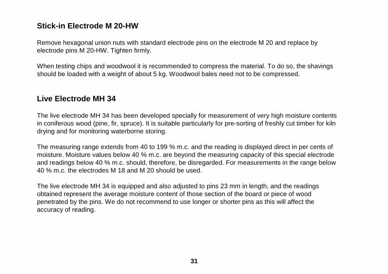
Stick-in Electrode M 20-HW Remove hexagonal union nuts with standard electrode pins on the electrode M 20 and replace by electrode pins M 20-HW. Tighten firmly. When testing chips and woodwool it is recommended to compress the material. To do so, the shavings should be loaded with a weight of about 5 kg. Woodwool bales need not to be compressed. Live Electrode MH 34 The live electrode MH 34 has been developed specially for measurement of very high moisture contents in coniferous wood (pine, fir, spruce). It is suitable particularly for pre-sorting of freshly cut timber for kiln drying and for monitoring waterborne storing. The measuring range extends from 40 to 199 % m.c. and the reading is displayed direct in per cents of moisture. Moisture values below 40 % m.c. are beyond the measuring capacity of this special electrode and readings below 40 % m.c. should, therefore, be disregarded. For measurements in the range below 40 % m.c. the electrodes M 18 and M 20 should be used. The live electrode MH 34 is equipped and also adjusted to pins 23 mm in length, and the readings obtained represent the average moisture content of those section of the board or piece of wood penetrated by the pins. We do not recommend to use longer or shorter pins as this will affect the accuracy of reading.

32
Press, or drive cautiously, both pins into the wood to be measured until both cap nuts touch it. Connect electrode to the meter socket (2) and set selector switch (4) to position »M«. Then press measuring key (7) and read result in per cent of moisture. When withdrawing the electrode, the pins can be loosened by slight sideways rocking movements across the grain. The cap nuts should be tightened by means of a spanner prior to a series of measurements. Test Standard for Wood Moisture Measuring Circuit The test standard (Ref. No. 6070) permits to check the meter as well as the connection cable and the measuring electrodes M 18 and M 20 both in respect to proper function and accurate readings. To do so, connect the cable to the meter and insert the two plugs of the cable into the bushing of the test standard. If the measuring electrodes is to be included in the check, connect electrode to the cable and insert the two electrode pins into the bushing of the test standard. Set selector switches to position X5 and Y9 and press measuring key (7). The meter should read 21.0 %. The admissible tolerance is ± 0.5 %. The meter and the test standard should have a temperature of about 20 °C.

33
General Information on Wood Moisture Measurement The measuring principle of most GANN Hydromette moisture meters is based on the electrical resistance or conductivity measuring method well known for many years. This method is based on the fact that the electrical resistance is dictated to a large extent by the wood moisture content. The conductivity of bone-dry timber is very poor and its resistance very high so that no current worth mentioning can flow. The conductivity of wood increases with increasing moisture content whereas its electrical resistance decreases. In the range above the fibre saturation point (about 30 % m.c.) readings become progressively less accurate depending on the species of wood, its specific weight and temperature. With European conifers and some exotic woods such as Meranti/ Lauan, greater measuring errors must be expected in the range above 40 % m.c. whereas relatively accurate readings can be obtained with oak, beech, white afara, etc. up to a range of 60 – 80 % m.c.. To achieve as accurate readings as possible, the samples selected should be measured at several spots. It should always be observed that the minimum penetration depth of the electrode pins, driven into the wood across the grain, is 1/4 and the maximum depth 1/3 of wood thickness. Testing frozen wood with a moisture content is excess of 20 % is not possible. For measurement of coniferous wood with high moisture content (40 to 200 % m.c.) the active electrode MH 34 should be used.

34
Effects of Wood Preservers Treatment of wood with organic preservers or impregnating agents has, in general, little effect on the meter readings. Treatment with preservatives containing salts or other inorganic constituents that change the conductivity of wood, however, has a great effect on the accuracy of the readings and as it is erratic, a suitable table correction cannot be provided. Moisture Checks on Plywood Some of the various types of glue used in the manufacture of plywood have a lower electrical resistance than the wood. This will affect the accuracy of electrical resistance moisture meters when the electrode pins get in touch with a glue line. The meter will then show too high moisture content. To find out whether a conductive glue has been used in manufacturing the plywood to be tested, drive the electrode pins to a depth of no more than half the thickness of the first ply and read the result. Then drive the pins further into the plywood until they come in contact with the first glue line. If the reading now displayed is not noticeable higher than before, the glue may be considered to have no effect on the accuracy of the meter readings.
35
Static Electricity At wood moisture contents below 10 %, circumstances such as low air relative humidity, friction during timber handling or highly insulated surroundings may cause static electricity of very high voltages. The operator too may contribute, e.g. by his clothing or shoes made of man-made fibre, to build up a static charge. This may result not only in fluctuating or negative readings, but can also destroy transistors and integrated circuits used in manufacturing the moisture meter. The results can be markedly improved, if the operator stands perfectly still and avoids moving the meter and the measuring cable while taking the reading. Especially at the outlet of veneer dryers, very high static charges have to be expected. Therefore, moisture measurements of dried veneer should be made only after the static charge has been sufficiently reduced, what can be sped up by employing suitable grounding measures. Wood Moisture Equilibrium - Equilibrium Moisture Co ntent When storing wood for a sufficiently long space of time in a constant ambient atmosphere, it will adopt the moisture content that corresponds to this climate which is called Wood Moisture Equilibrium . Once the wood has reached its moisture equilibrium, it will neither give off moisture nor absorb it from the air, unless the ambient atmosphere changes. The following table shows some moisture equilibrium values which wood adopts at the various conditions specified.

36
Wood Moisture Equilibrium
Air Temperature in °C
10° 15° 20° 25° 30° Air relative humidity
Wood Moisture Content
20% 4,7% 4,7% 4,6% 4,4% 4,3%
30% 6,3% 6,2% 6,1% 6,0% 5,9%
40% 7,9% 7,8% 7,7% 7,5% 7,5%
50% 9,4% 9,3% 9,2% 9,0% 9,0%
60% 11,1% 11,0% 10,8% 10,6% 10,5%
70% 13,3% 13,2% 13,0% 12,8% 12,6%
80% 16,2% 16,3% 16,0% 15,8% 15,6%
90% 21,2% 21,2% 20,6% 20,3% 20,1%

37
Monitoring Kiln Drying The HYDROMETTE RTU 600 allows continual control and supervision of wood moisture content and equilibrium moisture (EMC) inside the closed drying kiln. The portable meter can be used to supervise any number of dry kilns, while the measuring station equipment is separately required for each kiln. The monitoring system is suitable for both brick-built and pre-fabricated compartment kilns of any design. In each kiln, any desired number of wood moisture measuring points can be provided. For monitoring equilibrium moisture content and temperature measurement only one each measuring point is required unless the fans are periodically reversed. In the latter case, one each EMC and temperature measuring should be installed at the two opposite sides in direction of air flow as these readings should always be taken at the air entry side of the kiln load. For taking moisture measurements on wood in the dry kiln during the drying process, set selector switches (4) and (5) to position appropriate to species of wood to be measured, and temperature selector switch (6) to temperature prevailing in the kiln. For E.M.C. measurements set selector switch (4) to position »6« and selector switch (5) to position »4«. For temperature measurement set selector switch (4) to position »200°«. For M.C. and E.M.C. measurements in dry kilns, special electrodes and probes have to be used. They should be connected with the measuring point selector switch TKMU by means of Teflon insulated, heat-proof special cables. Whenever readings are to be taken, the Hydromette moisture meter is to be connected to the measuring point selector switch using the measuring cable MK 8. The measuring point selector switch TKMU is available for connection of up to 6 or 10 MC and EMC measuring points, and also optionally with connection device for one or two temperature measuring points.

38
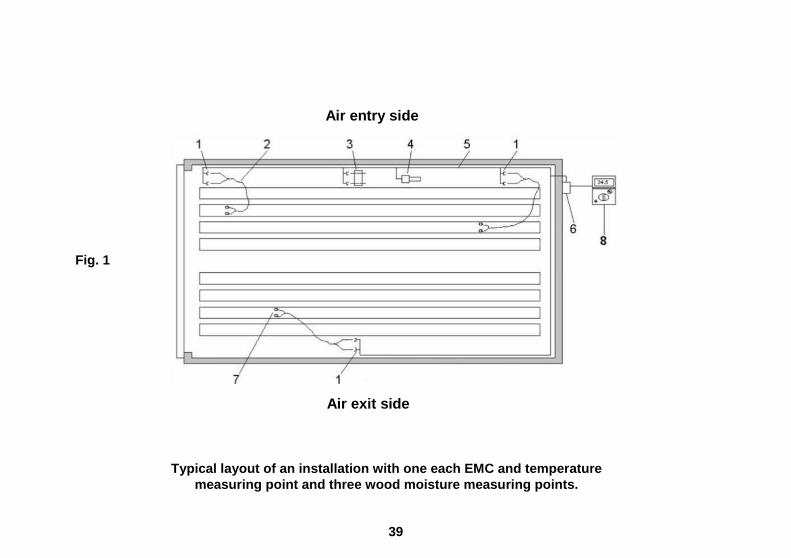
For arrangement of the wood moisture and equilibrium moisture measuring points in the dry kiln, proceed as described hereinafter. Assembly Instructions Installation involves merely the installation of the measuring point selector switch (6) outside the kiln, mounting a wall connector (1) for each MC and EMC measuring point inside the kiln, and installing the main cables (5). The picture on the next side shows a possible installation in a double track compartment kiln. The wall connector (1) for each MC and EMC measuring point is bolted to the inside kiln wall. Where several kiln trucks are in use, it is advisable to arrange the wall connectors near the end of each truck so that the electrode connecting cables (2) can be conveniently connected when the trucks are in position. Suitable mounting screws and spacers are included in the delivery of complete measuring point assemblies. The EMC (3) and temperature (4) measuring points are to be installed on the air entry side of the kiln load. In case of reversing type dry kilns, i.e. where the fans run alternately in forward and inverse direction, EMC and temperature measuring points are to be installed on either side in direction of the air flow. The HYDROMETTE wood moisture meter (8) is connected to the selector switch by means of the standard cable MK 8.
39
Air entry side Fig. 1 Air exit side
Typical layout of an installation with one each EMC and temperature measuring point and three wood moisture measuring p oints.

40
The wall connector for the EMC probe is best mounted near the existing dry
and wet bulb thermometer or hygrometer. The probe should lie directly in the air flow, but not close to the spraying system. It should be protected against drip water by an aluminium cover as shown in Fig. 2. Further, it should also be protected against direct radiating heat.
The measuring station selector switch should be installed outside the kiln in a
position combining ready accessibility with the shortest cable lines to the wall connectors inside the kiln. The selector switch can also be mounted outdoors, but should then be protected against direct exposure to influence of the weather.
Cables should be run from the kiln interior to the outside in an aluminium or
plastic conduit. In brick-built kilns, the tube should be grouted in with a slight downward angle to the outside. In pre-fabricated kilns, it should be welded in or mounted with a sealing flange and should also slope at a slight downward angle.
In all cases, the cable duct should be sealed on the inside after cables have been installed, either by sealing compound or drilled rubber plug. Fig. 2 The main cables (5) joining the wall connectors (1) up to the measuring point selector switch (6) are fitted on one end with cable shoes which need only be plugged over the terminal pins in the selector switch. The other end of the cable must be plugged into the cable shoes mounted onto the wall connectors after stripping the ends of the two conductors. Then the sockets of the two cable shoes must be crimped to tighten the two conductors and to ensure good contact.

41
Inside the kiln, cables should be fixed direct to the kiln wall by means of the cable strings included in the delivery. They must not be laid in conduits, unless they are laid in dry kilns made of wooden panels. Each standard wood moisture measuring point consists of two stainless steel electrodes 10, 15 and 25 mm long, one electrode cable 4 m long, one wall connector including spacers and fastening screws and one main cable 10 m long with cable strings and fastening screws. The 15 mm and 25 mm electrodes are also available with Teflon insulation upon special request. For very thick woods also electrodes 40 mm long are available in insulated and uninsulated design. The penetration depth should be 1/3 of the thickness of the boards to be measured but at least 10 mm.
Preparing Wood Moisture Measuring Points Measuring points should always be arranged roughly in the centre of the stack. Where several kiln trucks are used or stacks loaded into the kiln, it is recommendable to distribute the measuring points among several stacks and at different levels.
When loading the kiln truck or piling the pallets, drill holes of 3 mm dia. to the full electrode penetrating depth into the board selected. Holes should be across the grain, 3 cm apart (Fig. 3). Drive the electrodes into the board using the special electrode tool available for driving-in and extracting electrodes. Insert the plugs of the electrode cable into the connecting bores of the electrodes and lead the cable around the side or back of the stack.
Take care not to damage the cable when stacking the remainder of the wood on the truck or pallet.

42
When the truck or pallet is in position, connect the electrode cable to the wall connector in the kiln.
EMC Measuring Point The EMC measuring point consists of an electrode holder with 50 wooden EMC sensors, one wall connector and a main cable 10 m long with fastening strings. Pull the plug-in type electrode holder from the wall connector and loosen knurled nuts as far as the stop. EMC is measured on a thin specimen of White Afara. The sensor has to be placed between the clamps of the electrode holder, with the grain at right angles to them. Then tighten the knurled nuts as far as they will go. Now plug the holder into the sockets of the wall connector.
The sensor has to be replaced after each drying cyc le.
Temperature Measuring Point In addition to MC and EMC measuring points also a temperature measuring point can be installed and connected to the measuring point selector switch for taking readings with the Hydromette RTU 600. It should preferably be placed close to the EMC measuring point. The temperature probe is supplied in standard design with a connection cable 10 m long and a fastening bracket. Longer cables, also for MC and EMC measuring points, are available on request.

43
Final Remarks The meaning of the term »wood moisture « is obvious and requires no explanation, except perhaps that the moisture percentage always refers to the dry weight. »Wood equilibrium moisture « (EMC), however, a factor of the greatest importance in effective drying, is not always clearly understood. It means the degree of moisture a piece of wood attains if stored long enough in a given atmosphere, i.e. at a definite ambient temperature and air humidity. The »drying gradient « finally is the ratio between wood moisture and equilibrium moisture. This can be expressed in the formula Wood Moisture
__________________ = Drying Gradient Equilibrium Moisture Conventional drying schedules frequently refer to the air relative humidity or wet bulb depression (psychrometric difference). The following table permits converting wet bulb depression values into EMC values and vice versa.

44
Dry Bulb Temperature (°C) (Drying Temperature)
35 40 45 50 55 60 65 70 75 80 85 EMC Values
25 1.6 2.5 3.2 3.4 3.6 3.7 3.8 3.9 3.9
20 2.0 3.0 3.5 4.2 4.6 4.7 4.8 4.9 4.9 4.8 4.7
18 3.0 3.9 4.3 4.9 5.2 5.3 5.4 5.4 5.4 5.3 5.3
16 4.0 4.9 5.3 5.7 5.8 5.9 6.0 6.0 6.0 5.9 5.8
14 5.4 5.9 6.2 6.5 6.7 6.7 6.7 6.6 6.6 6.5 6.4
12 6.5 7.0 7.2 7.5 7.7 7.7 7.5 7.5 7.4 7.3 7.2
10 7.8 8.2 8.4 8.6 8.7 8.6 8.5 8.4 8.3 8.2 8.0
9 8.5 8.9 9.1 9.3 9.3 9.2 9.1 9.0 8.8 8.7 8.5
8 9.3 9.6 9.7 9.8 9.8 9.8 9.7 9.6 9.5 9.3 9.2
W
et b
ulb
depr
essi
on
7 10.2 10.4 10.6 10.7 10.7 10.6 10.5 10.4 10.2 9.9 9.8

45
Dry Bulb Temperature (°C) (Drying Temperature)
35 40 45 50 55 60 65 70 75 80 85 EMC Values
6 11.2 11.4 11.5 11.6 11.5 11.4 11.3 11.1 10.8 10.7 10.5
5 12.2 12.4 12.6 12.7 12.6 12.5 12.4 12.2 11.8 11.7 11.4
4 13.6 13.8 13.9 13.9 13.8 13.7 13.6 13.4 13.1 12.8 12.6
3 15.3 15.7 15.7 15.5 15.4 15.3 15.0 14.8 14.5 14.3 14.0
2.5 16.7 16.8 16.8 16.6 16.4 16.3 16.1 15.8 15.5 15.3 14.9
2 18.0 18.0 18.0 17.8 17.6 17.4 17.1 16.8 16.5 16.3 16.0
1.8 18.6 18.7 18.7 18.5 18.3 18.0 17.6 17.3 17.0 16.7 16.4
1.6 19.3 19.4 19.4 19.2 19.0 18.7 18.3 18.0 17.7 17.3 17.0
1.4 19.9 20.0 20.0 19.8 19.6 19.3 19.0 18.6 18.3 17.9 17.6
W
et b
ulb
depr
essi
on
1.2 20.8 20.9 20.9 20.7 20.5 20.3 19.8 19.4 19.0 18.7 18.3

46
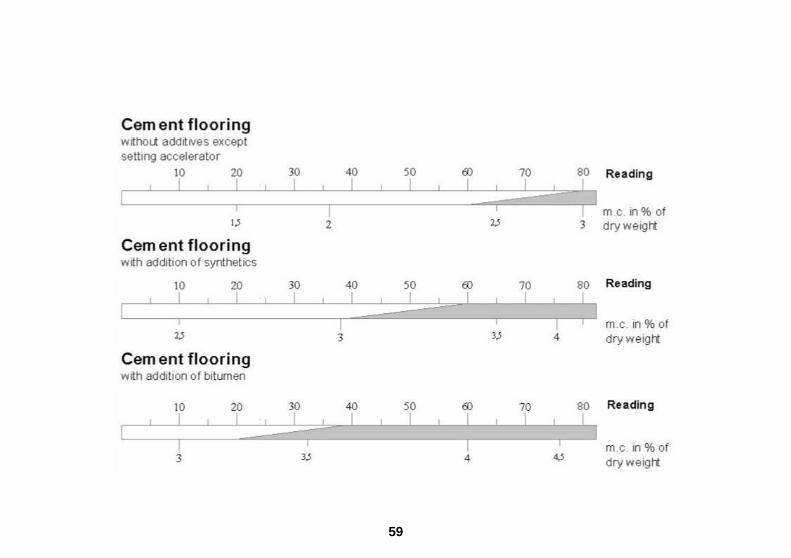
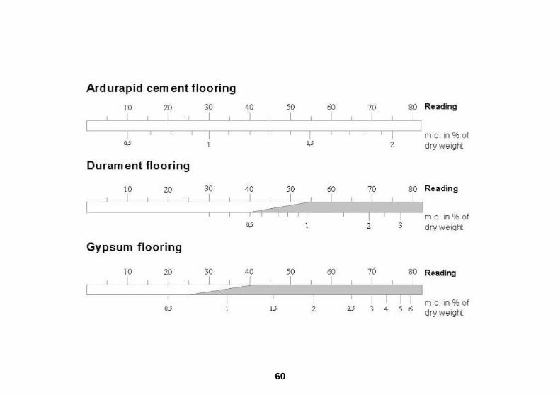
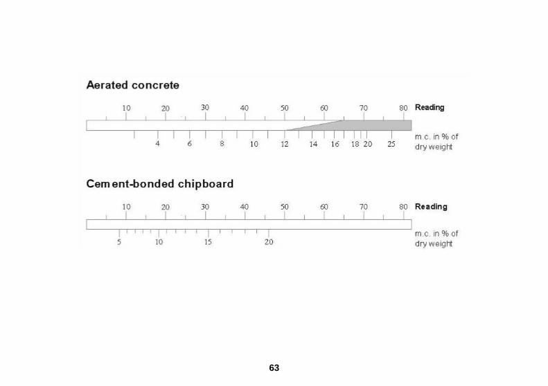
Operating Instructions for Moisture Measurement of Building Materials Set selector switch (4) to position »B«. Connect selected measuring electrode to the meter socket (1) by means of the measuring cable MK 8 and drive-in or stick-in electrode into the material to be measured. Press measuring key (7) and read off result displayed by the LCD readout (3). Convert reading into per cent of moisture by means of scale graphs listed at the end of this section. Connection of the Electrodes Different electrodes can be used with the meter depending on the material to be tested. The electrodes are connected to the meter socket (1) by means of the measuring cable MK 8. On the meter side, this cable is fitted with a BNC plug. Turn clockwise to lock it. To disconnect, turn notched fastening ring anti-clockwise and draw off plug. Do not use force and do not pull on the cable.

47
Testing Set Building Materials For testing soft building materials, the drive-in electrode M 20 should be used, whereas hard building materials such as concrete and cement flooring are to be measured with the stick-in electrodes M 6 or M 21 / 100, using contact paste. For penetration measurements, up to a depth of 250 mm, on concrete or masonry, the special electrodes M 21 / 250 are available. The special stick-in electrodes M 20-Bi available with insulated pins 200 or 300 mm long, are specially designed for measurements of materials hidden beneath another panel or cover- ing, or otherwise inaccessible to other electrodes. Special measurement caps type M 20-OF 15 are available for surface measurements (e.g. on concrete, etc.). They can be used only in conjunction with the electrode M 20. Drive-in Electrode M 20 For penetration measurements, up to a depth of 70 mm, on soft, set building materials (gypsum, plaster, etc.), drive electrode pins into the material to be tested (the electrode body is of impact resistant plastic). Take care that both pins of the electrode are driven only into the material to be tested. When withdrawing the electrode, the pins can be loosened by slight sideways rocking movements. The cap nuts should be tightened by means of a spanner prior to a series of measurements. Loose pins may easily break.

48
When the meter is supplied with the M 20 electrode as initial equipment, 10 spare pins 16 and 23 mm long (commercial steel nails) are included in the delivery. They can be used for measurements up to a depth of 20 mm or 30 mm respectively. For measurements to greater depths, they can be replaced by longer pins but it should be noted that the liability to breakage or bending increases with the length of the pins. Surface Measurement Caps M 20-OF 15 For surface measurements on smooth materials, the two hexagonal union nuts have to be unscrewed and replaced by the surface measurement caps. To perform the measurement, the two contact surfaces should be firmly pressed onto the material being measured. The measurement depth is about 3 mm. Particles adhering to the measurement surface should be regularly removed. If the elastic plastic pads should once be damaged, they can be re-ordered and stuck on using a commercially available instant adhesive on cyanate basis.
Measuring errors can be caused by a contaminated or dirty surface (e.g. oil). Stick-in Electrode M 6 The two electrodes exclusively designed for moisture checks on set building materials are pressed, at approx. 10 cm apart, into the material to be tested. Both electrodes have to be inserted into the same type of building material. Also, the section to be measured must be coherent and not be crossed by an- other material. If the material is too hard to press in the electrodes by hand (e.g. cement flooring, concrete, etc.) drill 6 mm holes and fill them with contact paste. Then stick the pins into the contact paste. When the meter is supplied with the M 6 stick-in electrodes as initial equipment, two pins 23 mm, 40 mm and 60 mm long are included in the delivery. They are suitable for measurements in depths up to 30 mm, 50 mm or 70 mm respectively. Where hard building materials are involved and no c ontact paste is used, a considerable measuring error must be expected (the values indicated will be too low).
49
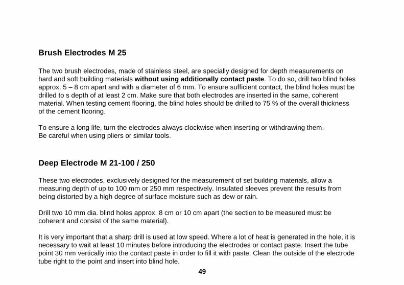
Brush Electrodes M 25 The two brush electrodes, made of stainless steel, are specially designed for depth measurements on hard and soft building materials without using additionally contact paste . To do so, drill two blind holes approx. 5 – 8 cm apart and with a diameter of 6 mm. To ensure sufficient contact, the blind holes must be drilled to s depth of at least 2 cm. Make sure that both electrodes are inserted in the same, coherent material. When testing cement flooring, the blind holes should be drilled to 75 % of the overall thickness of the cement flooring. To ensure a long life, turn the electrodes always clockwise when inserting or withdrawing them. Be careful when using pliers or similar tools. Deep Electrode M 21-100 / 250 These two electrodes, exclusively designed for the measurement of set building materials, allow a measuring depth of up to 100 mm or 250 mm respectively. Insulated sleeves prevent the results from being distorted by a high degree of surface moisture such as dew or rain. Drill two 10 mm dia. blind holes approx. 8 cm or 10 cm apart (the section to be measured must be coherent and consist of the same material). It is very important that a sharp drill is used at low speed. Where a lot of heat is generated in the hole, it is necessary to wait at least 10 minutes before introducing the electrodes or contact paste. Insert the tube point 30 mm vertically into the contact paste in order to fill it with paste. Clean the outside of the electrode tube right to the point and insert into blind hole.

50
Prepare the second hole in the same way. Connect measuring cable to the electrode rod and insert the latter into the electrode tube. Press the contact paste to the end of the hole by exerting pressure with the rod. Connect the measuring cable to the meter, press measuring key and read off result. Warning The readings may under some circumstances be distorted if there is too much contact material in the electrode tube or if an electrode tube contaminated with contact paste is repeatedly removed and inserted. Contact Paste The contact paste is supplied in quantities of approx. 450 g in a plastic box sealed with a screw cap. It is used to produce a good contact between the electrode point and the building material to be measured or to serve as an extension to the electrode point. The moisture displaced by the drilling process is reconducted to the material to be measured by the water contained in the highly conductive contact paste. The surface of the material to be measured must not be smeared with the contact paste as the latter has a high conductivity. When using the M 6 electrodes, it is advisable for an appropriate amount of the paste to be rolled into a thin strand and pressed into the hole with the reverse end of the drill. It is possible to keep the contact paste mouldable by adding normal tap water. The quantity contained in a box is generally sufficient for approx. 50 measurements.

51
Flat Electrodes M 6-Bi 200 / 300 These two electrodes are exclusively designed for measurement of insulating material through the edge joint of the cement flooring. Spaced about 5 to 10 cm, they have to be pushed forward through the edge joint along the cement flooring down to the insulating layer. Particular care should be taken to avoid that the shrinking hose of the pins is not damaged because otherwise a moist cement flooring can cause measuring errors. The cap nuts should be tightened by means of a spanner or pliers. The two flat electrodes can only be used with the M 6 electrode handle. Stick-in Electrodes M6- 150 / 250 The very thin electrode pins are specially designed for testing building or insulating materials for moisture content, if the pin holes shall be kept as small as possible. The two 2 mm dia. pins, made of ductile high-grade steel, can, for example, be sticked approx. 3 to 5 cm apart through the edge joint of the cement flooring into the insulating layer. For use of these pins being specially developed for measurements through the cross joint of tiles, a special 3 mm dia. hard-matel drill 160 mm long (Ref. No. 6078) is available. It permits drilling a hole through the cement flooring up to the insulating layer. The electrode pins should be spaced, if possible, no more than 10 cm (maximum 15 cm). The electrode pins can be used with the handles of the M 6 electrodes (Ref. No. 3700) and with the M 20 electrode (Ref. No. 3300).
52
Test Standard for Structural Moisture Measuring Sec tion The optionally available test standard (Ref. No. 6071) permits the user to check proper function of the structural moisture measuring section of the meter as well as of the connection cable MK 8 and of the measuring electrodes M 6 and M 20 at any time. To do so, connect the cable of the meter and insert the two plugs in the bushing of the test adapter. If an electrode is to be included in the check, connect it to the cable and insert the two pins into the bushings. Set selector switch (4) to position »B« and press measuring key (7) when a reading of 45 digits should be obtained. A tolerance of ± 2 digits is admissible.

53
Stick-in Electrode M 20-Bi 200/300 For measurement of hidden beams in framework buildings and, particularly, in insulated flat roofs or facades. In order to prevent damage to the insulation of the points, it is advisable not to drive them into hard building materials (plaster, gypsum plaster boards, etc.). Insulating materials such as fibre glass, rock wool, etc. can, of course, be easily penetrated. Otherwise, preliminary 10 mm dia. holes have to be drilled. The insulated points allow correct measurement uninfluenced by the moisture content of other material traversed by the electrode pins. Remove hexagonal union nuts with standard electrode pins from the electrode M 20 and fit electrode pins M 20-Bi. Tighten firmly. Equilibrium Moisture Content What are generally referred to as equilibrium moisture value relates to an ambient temperature of 20 °C and an ambient air humidity of 65 % R.H. These values are frequently also termed »air dry «. They must not however be confused with the values at which the material can be processed or worked. Before painting or laying a floor, the diffusion capacity of the covering and future ambient conditions in the room must be taken into consideration. When laying PVC flooring in a centrally heated room with an anhydrite sub-floor, the flooring cannot be laid until the floor has dried to approx. 0.6 % m.c.
54
On the other hand, parquetry flooring can be laid on a cement floor in a room with normal stove heating, with a moisture range of 2.5 to 3.0 % m.c. The long term ambient conditions must also be taken into account when assessing wall surfaces. Lime stuff in an old vaulted cellar may have a moisture content of 2.6 % and still be treated. But a moisture content above only 1 % is considered too high for gypsum plaster in a centrally heated room. It is of prime importance to consider ambient conditions when determining the moisture content of a building material. All materials are exposed to constantly changing temperatures and air humidities. The effect on the moisture content of the material basically depends on the thermal conductivity, heat capacity, resistance to diffusion of water vapour and the hygroscopic properties of the material. The »desired« moisture content of a material, therefore, corresponds to its mean equilibrium moisture under the changing ambient conditions to which the material is constantly exposed. Air humidity values for Central Europe lie in the range of approx. 45 to 65 % R.H. in summer and approx. 30 to 45 % in winter. A lot of damage occurs in winter, particularly in centrally heated rooms, as a result of these great swings. It is not possible to set universally valid values. It always requires the craftsman's and the expert's experience to draw correct conclusions from any readings. In the case of inorganic building materials, the water content is generally given as a percentage of dry weight. The hygroscopic water content of any material is to a large extent proportional to its density, i.e. for all apparent densities of a building material, the same value is shown when giving the moisture in percentage of dry weight, but at twice the apparent density, a reading in percentage of volume would be twice as great.
55
Equilibrium moisture values
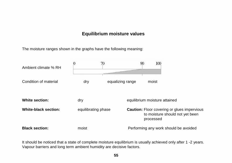
The moisture ranges shown in the graphs have the following meaning: Ambient climate % RH Condition of material dry equalizing range moist White section: dry equilibrium moisture attained White-black section: equilibrating phase Caution: Floor covering or glues impervious
to moisture should not yet been processed Black section: moist Performing any work should be avoided It should be noticed that a state of complete moisture equilibrium is usually achieved only after 1 -2 years. Vapour barriers and long term ambient humidity are decisive factors.

56
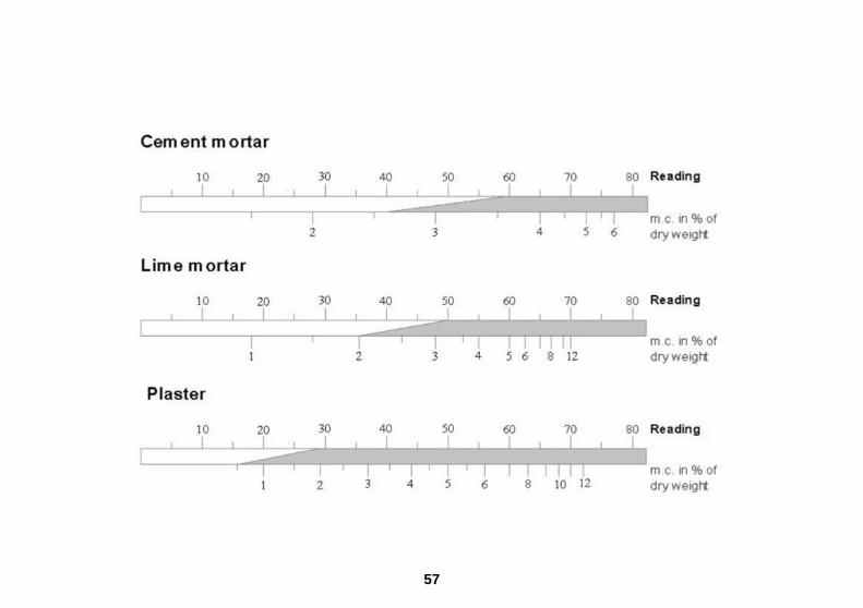
Table of Comparison Air Humidity - Structural Moi sture
57

58
59
60

61

62
63

64
Building or Insulating Materials Not Assignable to One of the Preceding Conversion Graphs Some building materials, e.g. brick, sand lime brick, etc., cannot be measured with the usual accuracy due to their varying mineral additives or burning times. This does not however mean that comparative measurements on the same material and on the same site would be of no value. Obtaining various high values may, for example, show the extent of a damp patch due to water damage. Or comparative measures on the dry inside and the damp outside of a wall may show how the drying process is progressing. Insulating materials, e.g. rock or glass wool, plastic foams, etc., cannot be measured in their dry condition due to their great insulating capacity. Readings fluctuate widely and even give minus values, due to endogenous statics. Damp to wet insulating materials can be measured in the range of 20 - 100 digits or scale divisions. Conversion to percentage by weight or volume percentage is, however, not possible. It is important that the insulating material is not over-penetrated by the electrodes. If this is done, an incorrect value may be shown as the underlying support is usually of a much higher moisture content.

65
Instructions for Non-Destructive Measurement of the Moisture Content of Building Materials Using the Active Electrodes MB 35 and B 50
Set selector switch »X« (4) to position »M«.
Connect electrode to meter socket (2) and apply it as described hereinafter.
Press measuring key (7) and read result displayed by LCD readout (3).
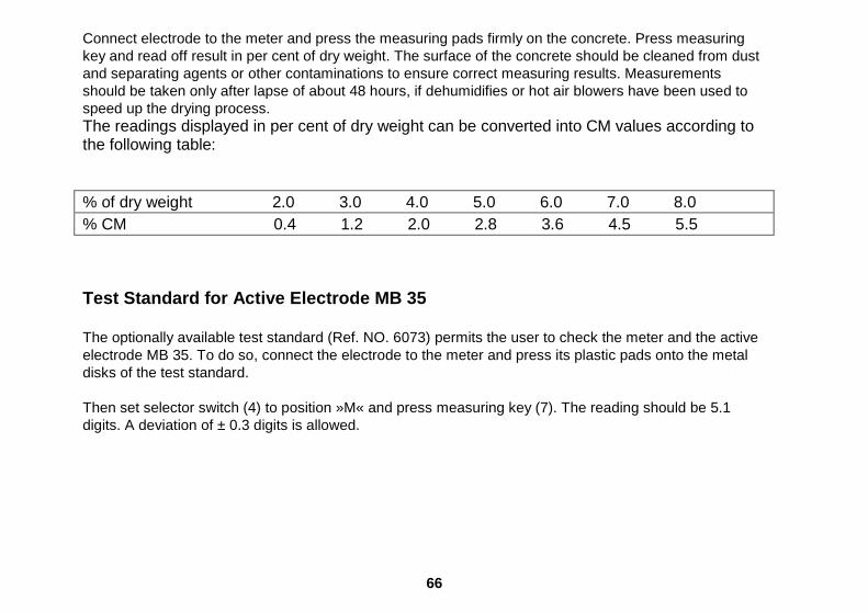
Active Electrode MB 35 The active electrode MB 35 has specially been developed for surface moisture measurement on concrete and sub-floorings and is suitable particularly for moisture checks prior to coating or gluing. The measuring range extends from 1.0 to 8.0 % of dry weight (according to oven test). The reading is displayed direct in per cent of moisture. The electrode is fitted, as standard equipment, with the surface measuring caps M 20-OF 15 with elastic contact pads of conductive plastic material. The pads are glued on their support which in turn are screwed on the electrode handle. Make sure that the measuring caps are properly screwed down. Exchange the elastic measuring pads in case of wear or damage. Fix the new pads on the support plate by means of a commercially available instant adhesive on cyanate basis. Use of active electrode MB 35
66
Connect electrode to the meter and press the measuring pads firmly on the concrete. Press measuring key and read off result in per cent of dry weight. The surface of the concrete should be cleaned from dust and separating agents or other contaminations to ensure correct measuring results. Measurements should be taken only after lapse of about 48 hours, if dehumidifies or hot air blowers have been used to speed up the drying process. The readings displayed in per cent of dry weight can be converted into CM values according to the following table: % of dry weight 2.0 3.0 4.0 5.0 6.0 7.0 8.0 % CM 0.4 1.2 2.0 2.8 3.6 4.5 5.5 Test Standard for Active Electrode MB 35 The optionally available test standard (Ref. NO. 6073) permits the user to check the meter and the active electrode MB 35. To do so, connect the electrode to the meter and press its plastic pads onto the metal disks of the test standard. Then set selector switch (4) to position »M« and press measuring key (7). The reading should be 5.1 digits. A deviation of ± 0.3 digits is allowed.
67
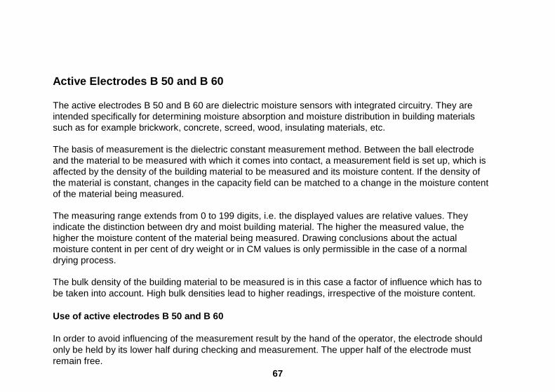
Active Electrodes B 50 and B 60 The active electrodes B 50 and B 60 are dielectric moisture sensors with integrated circuitry. They are intended specifically for determining moisture absorption and moisture distribution in building materials such as for example brickwork, concrete, screed, wood, insulating materials, etc. The basis of measurement is the dielectric constant measurement method. Between the ball electrode and the material to be measured with which it comes into contact, a measurement field is set up, which is affected by the density of the building material to be measured and its moisture content. If the density of the material is constant, changes in the capacity field can be matched to a change in the moisture content of the material being measured. The measuring range extends from 0 to 199 digits, i.e. the displayed values are relative values. They indicate the distinction between dry and moist building material. The higher the measured value, the higher the moisture content of the material being measured. Drawing conclusions about the actual moisture content in per cent of dry weight or in CM values is only permissible in the case of a normal drying process. The bulk density of the building material to be measured is in this case a factor of influence which has to be taken into account. High bulk densities lead to higher readings, irrespective of the moisture content. Use of active electrodes B 50 and B 60 In order to avoid influencing of the measurement result by the hand of the operator, the electrode should only be held by its lower half during checking and measurement. The upper half of the electrode must remain free.

68
Special feature of the active electrode B 60 The active electrode B 60 is equipped with a selector switch to set a limit value. It allows in conjunction with the also incorporated acoustic signal generator judgement of the tested building material without direct sight on the LCD readout. Whenever the readings exceed the preset limit value, a whistle signal sounds. In the range between 30 and 70 digits, the signal tolerance is ± 2 digits, and in the range between 80 and 140 digits ± 3 digits.
69
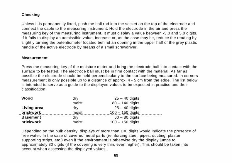
Checking Unless it is permanently fixed, push the ball rod into the socket on the top of the electrode and connect the cable to the measuring instrument. Hold the electrode in the air and press the measuring key of the measuring instrument. It must display a value between -5.0 and 5.0 digits. If it fails to display an admissible value, increase or, as the case may be, reduce the reading by slightly turning the potentiometer located behind an opening in the upper half of the grey plastic handle of the active electrode by means of a small screwdriver.
Measurement Press the measuring key of the moisture meter and bring the electrode ball into contact with the surface to be tested. The electrode ball must be in firm contact with the material. As far as possible the electrode should be held perpendicularly to the surface being measured. In corners measurement is only possible up to a distance of approx. 4 - 5 cm from the edge. The list below is intended to serve as a guide to the displayed values to be expected in practice and their classification:
Wood dry moist
25 – 40 digits 80 – 140 digits
Living area brickwork
dry moist
25 – 40 digits 100 – 150 digits
Basement brickwork
dry moist
60 – 80 digits 100 – 150 digits
Depending on the bulk density, displays of more than 130 digits would indicate the presence of free water. In the case of covered metal parts (reinforcing steel, pipes, ducting, plaster supporting strips, etc.) even if the environment is otherwise dry the display jumps to approximately 80 digits (if the covering is very thin, even higher). This should be taken into account when assessing the displayed values.
70
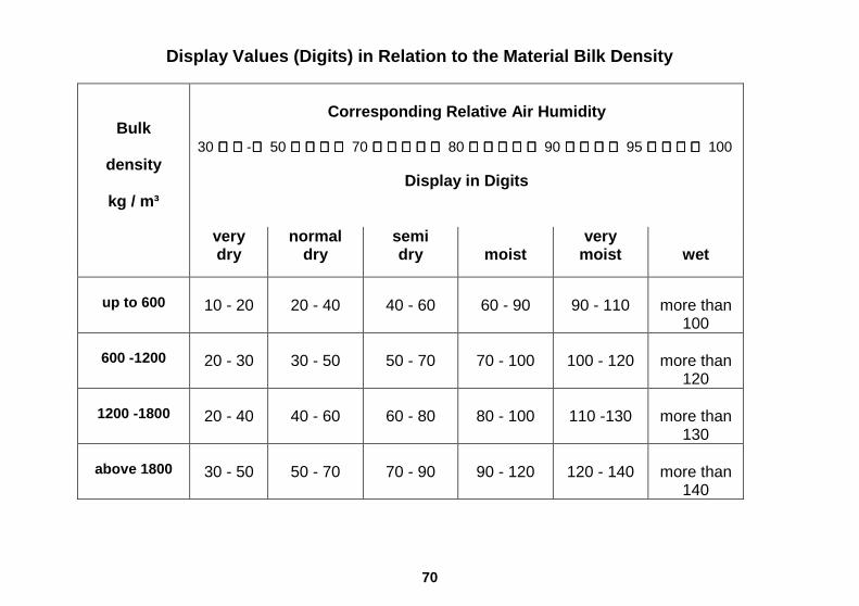
Display Values (Digits) in Relation to the Material Bilk Density
Bulk
density
kg / m³
Corresponding Relative Air Humidity
30 - 50 70 80 90 95 100
Display in Digits
very dry
normal dry
semi dry
moist
very moist
wet
up to 600
10 - 20
20 - 40
40 - 60
60 - 90
90 - 110
more than
100
600 -1200
20 - 30
30 - 50
50 - 70
70 - 100
100 - 120
more than 120
1200 -1800
20 - 40
40 - 60
60 - 80
80 - 100
110 -130
more than
130
above 1800
30 - 50
50 - 70
70 - 90
90 - 120
120 - 140
more than
140
71
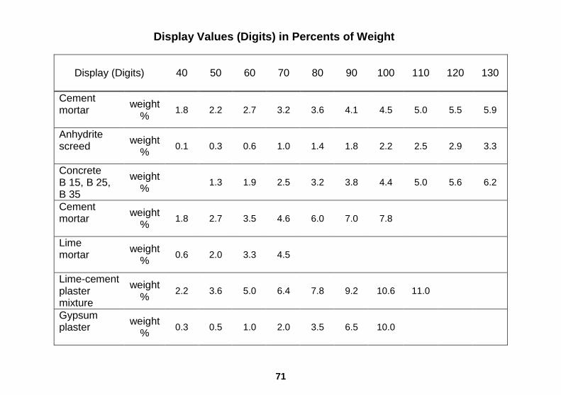
Display Values (Digits) in Percents of Weight
Display (Digits)
40 50 60 70 80 90 100 110 120 130
Cement mortar
weight %
1.8 2.2 2.7 3.2 3.6 4.1 4.5 5.0 5.5 5.9
Anhydrite screed
weight %
0.1 0.3 0.6 1.0 1.4 1.8 2.2 2.5 2.9 3.3
Concrete B 15, B 25, B 35
weight %
1.3 1.9 2.5 3.2 3.8 4.4 5.0 5.6 6.2
Cement mortar
weight %
1.8 2.7 3.5 4.6 6.0 7.0 7.8
Lime mortar
weight %
0.6 2.0 3.3 4.5
Lime-cement plaster mixture
weight %
2.2 3.6 5.0 6.4 7.8 9.2 10.6 11.0
Gypsum plaster
weight %
0.3 0.5 1.0 2.0 3.5 6.5 10.0

72
Readings in digits depending on the moisture in weight per cent. The displayed values are guide values. They refer to a depth of 1.5 to 3 cm in the case of a measurement on the surface and a normal drying process. Weight percentages are according to an oven test at 105 °C, for gypsum and anhydrite binders at 40 °C.
Note
The references and tables concerning permissible or customary moisture proportions in practice contained in the Operating Instructions and the general definitions have been taken from the specialist literature. No guarantee of correctness can therefore be given. The conclusions each user may draw for his own purposes from the measurement results are based on the individual circumstances and the knowledge he has gained from his professional activities.

73
Instructions for Moisture Measurement in Building M aterials on the Basis of the Measurement of the Relative Air Humidity using the active electrodes RF-T 31 and RF-T 36
Set selector switch »X« (4) to position »M«.
Connect selected active electrode to the meter socket (2).
Press measuring key (7) and read off result displayed (in % R.H.) by the LCD readout (3) .
Technical specifications Measuring range: 5 to 98 % R.H. for short periods.
For continuous or long period measurements in the range above 80 % R.H., a special calibration is required for the measuring sensors.
Admissible operating temperature -10 °C to +60 °C f or short periods for the meter and the electrodes: 0 °C to +50 °C for long periods Admissible ambient conditions for the storage of the meter -10 °C to +60 °C for s hort periods and the electrodes: 5 °C to +40 °C for long per iods 5 % to 98 % R.H. for short periods *) 35 % to 70 % R.H. for long periods *) *) not condensing
74
Measurement of the Relative Air Humidity / Water Activity in Building Materials This method is usually used for depth measurements in old buildings (sandstone, rough stone, wet walls with efflorescence, etc.) where measurements based on the resistance measurement method give no reproducible results. For this purpose the active electrode RF-T 31 with special tube lengths of 250 and 500 mm is used. In the case of measurements over a longer period at several points or at various depths, the drilled holes should be secured and closed by means of a masonry sleeve / bore hole adapter. The method of measuring the relative air humidity / equilibration moisture in cement flooring is chiefly used in Great Britain and the Scandinavian countries. The active electrode RF-T 36 has been specially developed for this measuring procedure. Compared with non-destructive measurement or resistance measurement, it is however very time-consuming and requires relatively large holes. Reliability for the floor layer/finisher is but on the other hand very good, if it is possible to wait for moisture balance (relative air humidity of the surroundings equal to that of the hole). This method also increases reliability in cases where there is not adequate information concerning the composition of the cement flooring. Use of the active electrode RF-T 31 For deep measurements in building materials by means of the relative air humidity, in addition to the probe with a sensing tube length of 250 or 500 mm a bore hole adapter consisting of a masonry sleeve of 150, 250 or 500 mm length should be used.

75
For the measurement a blind hole of 16 mm diameter should be drilled down to the required measuring depth. It is important to use a sharp drill, with a high number of impacts and low speed. If the hole should heat up strongly it is necessary to wait for temperature equalization (30 - 60 minutes) before taking the measurement. The hole should be cleared of dust (by blowing). Then the hole adapter should be introduced as far as the end of the hole, pressed in and at the same time turned to the right. The adapter should be tightened to such an extent that the entire screw thread sits firmly in the brickwork, concrete, etc. Then the closure rod for sealing or the electrode RF-T 31 should be inserted. The moisture balance in the hole is achieved when temperature equalization exists (the same temperature in the hole, adapter and sensor tube) after approximately 30 minutes. Then the measurement value can be read off and assessed by means of the following graph. Use of the active electrode RF-T 36 For the measurement a blind hole of 12 - 1 4 mm diameter and minimum 25 mm and maximum 50 mm deep must be drilled. The depth of drilling depends on the required measurement depth or thickness of the screed. Blow the hole clear of dust and wait for temperature equalization. Push the piece of foam enclosed on to the electrode tube of the probe and adjust the distance and to seal it, then introduce it into the hole. The moisture balance in the hole is achieved when temperature equalization exists (the same temperature in the hole, adapter and sensor tube) after approximately 30 minutes. Then the measurement value can be read off and assessed by means of the following graph.

76

77
Damage to the Sensor The sensor can be rendered irreparable as a result of various mechanical or environmental influences. These include in particular: - Direct contact between the sensor and the fingers, - Direct contact with solid or adhesive materials or objects, - Measurement in atmospheres containing solvents, oil vapours and other high pro portions of harmful
substances. Measuring Errors Measurements below 20 % relative humidity and above 80 % relative humidity should be avoided over a long period as far as possible. In order to make exceeding the measuring range particularly easy to recognize, above 98 % relative humidity a 1 « appears on the left hand side of the display instead of the measured value. Other measured value distortions can occur as a result of screening with parts of the body (e.g. the hand) or blowing or speaking/breathing in the direction of the sensor. Note The sensor is not designed for continuous measurements above 80 % relative humidity. If continuous measurements have to be made in extreme regions special adjustments should be made by means of sensorcheck and a calibration liquid.

78
Instructions for Air Humidity Measurement using the active electrodes RF-T 28, RF-T 31, RF-T 32 and RF-T 36 Set selector switch »X« (4) to position »M«. Connect electrode to the meter socket (2). Press measuring key (7) and read off result displayed (in % R.H.) by the LCD readout (3). Technical Specifications Measuring range: 5 to 98 % R.H. for short periods.
For continuous or long period measurements in the range above 80 % R.H., a special calibration is required for the measuring sensors.
Admissible operating temperature -10 °C to +60 °C for short periods, for the meter and the electrodes: 0 °C to +50 ° C for long periods. Admissible ambient conditions for the storage of the meter -10 °C to +60 °C for short periods and the electrodes: 5 °C to +40 °C for long per iods.
5 % to 98 % R.H. for short periods *) 35 % to 70 % R.H. for long periods *) *) not condensing
79
Use of the active electrode RF-T 28 Hold the electrode in the air or fasten it at the desired measurement site and start the measuring process. For particularly precise measurements, especially below the usual room temperature (abt. 20 °C) or if there are substantial temperature diff erences between the electrode or meter and their surroundings, they should be exposed to the ambient atmosphere for approx. 10 - 15 minutes until temperature equalization. The sensor adapts itself to the surrounding atmosphere even in the switched-off condition. Response time of the air humidity sensor The response time of the sensor is very short so even gently moving air (generated by a slightly opened door or a window being not tight) may affect the reading. This is why no absolute standstill of the value displayed can be achieved unless the sensor is installed in an airtight box. The response time of the sensor in gently moving air is as follows for ambient temperatures from 20 °C to 25 °C
for 90 % of the humidity difference, approx. 20 seconds, for 95 °/6 of the humidity difference, approx. 30 s econds.
The adjustment time in still air or at very low air movement can be reduced by moving or turning the electrode (ventilating the sensor). Filter cap for electrode RF-T 28 For measurements in dust laden air, at emission of harmful substances or at high air speed, a sintered filter cap can be fitted after removal of the protection cap with venting slots. For protection of the sintered filter, fix then the plastic cap again.
80
If the filter becomes dirty it can be washed in residue-free cleaning liquid and / or blown from inside outwards with compressed air. With the sintered filter inserted, the response time will be considerably prolonged. Use of the active electrode RF-T 31 The sensor RF-T 31 can be supplied with insertion length of 250 or 500 mm and is mainly used for measuring the relative air humidity or the AW value in places difficult of access, in air ducts, in bulk materials or, in combination with a special adapter, in solid substances (e.g. brickwork, concrete, etc.). Hold the electrode at the point of measurement in the air or insert it or attach it at the required point with a fixture and start the measurement process. For particularly precise measurements, in particular at temperatures below usual room temperature (abt. 20 °C) or when there are considerable temperature differences between the actual temperature of the electrode or of the measuring instrument and that of the surrounding atmosphere, the instrument with its electrode should be exposed to the ambient climate for approximately 10 to 15 minutes or until temperature equalization. Here too, the sensor adapts itself to the surrounding atmosphere without being switched on. If it becomes dirty, the sintered filter cap can be washed in residue-free cleaning liquid and / or blown from inside outwards with compressed air. Response time of the air humidity sensor RF-T 31 The response time is delayed by the sintered filter cap. In exceptional cases it can be unscrewed. However, if this is done the danger of damage to the sensor is increased considerably. The response time of the air humidity sensor in moving air, with an ambient temperature of 20 to 25 °C is approx. 30 sec. for 95 % of the humidity difference without filter, or approx. 10 min. with filter.
81
Note If it becomes dirty, the inserted filter cloth can only be washed in distilled water and / or blown clear with slight excess pressure from inside outwards. Therefore its use in very dusty media should be avoided. Preferably the cleaning should be carried out from outside using a soft brush.
82
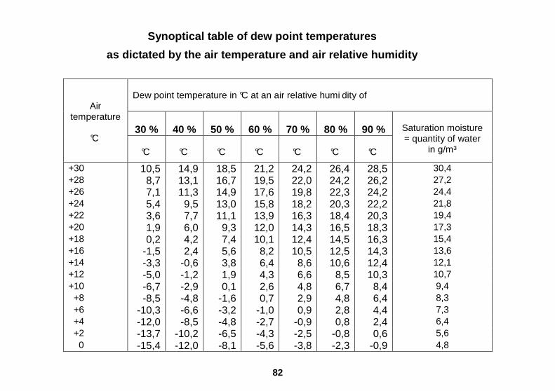
Synoptical table of dew point temperatures
as dictated by the air temperature and air relative humidity
Dew point temperature in °C at an air relative humi dity of
30 %
40 %
50 %
60 %
70 %
80 %
90 %
Air temperature
°C
°C
°C
°C
°C
°C
°C
°C
Saturation moisture = quantity of water
in g/m³
+30 10,5 14,9 18,5 21,2 24,2 26,4 28,5 30,4 +28 8,7 13,1 16,7 19,5 22,0 24,2 26,2 27,2 +26 7,1 11,3 14,9 17,6 19,8 22,3 24,2 24,4 +24 5,4 9,5 13,0 15,8 18,2 20,3 22,2 21,8 +22 3,6 7,7 11,1 13,9 16,3 18,4 20,3 19,4 +20 1,9 6,0 9,3 12,0 14,3 16,5 18,3 17,3 +18 0,2 4,2 7,4 10,1 12,4 14,5 16,3 15,4 +16 -1,5 2,4 5,6 8,2 10,5 12,5 14,3 13,6 +14 -3,3 -0,6 3,8 6,4 8,6 10,6 12,4 12,1 +12 -5,0 -1,2 1,9 4,3 6,6 8,5 10,3 10,7 +10 -6,7 -2,9 0,1 2,6 4,8 6,7 8,4 9,4 +8 -8,5 -4,8 -1,6 0,7 2,9 4,8 6,4 8,3 +6 -10,3 -6,6 -3,2 -1,0 0,9 2,8 4,4 7,3 +4 -12,0 -8,5 -4,8 -2,7 -0,9 0,8 2,4 6,4 +2 -13,7 -10,2 -6,5 -4,3 -2,5 -0,8 0,6 5,6 0 -15,4 -12,0 -8,1 -5,6 -3,8 -2,3 -0,9 4,8
83
Test and Calibrating Instructions for the Relative Humidity Circuitry of the Electrodes RF-T 28, 31 and 32 Using the Sensorcheck General Comments In general one has to differentiate between a test, a possibly necessary re-calibration and a special calibration for continuous measurement of more than 80 % humidity. Three test and calibrating liquids are available for the ranges of 10 to 50 %, 50 to 90 % and 80 to 98 %. The latter liquid is intended for special calibration of the high humidity range and is not to be used for general test or calibrating purposes. For testing or calibration of the standard moisture range, the liquid SCF 70 is to be employed. During testing or calibration, the electrode, the sensorcheck and the liquid must be of the same temperature. This temperature must be maintained throughout the procedure. Changes of temperature may be caused by a draft, by breathing or blowing or by holding the electrode tube, the sensorcheck or the liquid-ampoule in one's hand. Wrapping these components in Styropor or similar insulating material is recommended. Please follow the instructions stated on the wrapper of the liquid-ampoule regarding test, calibration and nominal value data closely.

84
Testing Different sensorcheck top pieces are required for each of the three types of electrodes. The following test sequence must be observed: 1. Unscrew sensorcheck top from bottom. 2. Electrode RF-T 28: Carefully pull-off the protective cap. If used, remove the dust cap first.
Electrode RF-T 31: Unscrew the sinter filter cap and withdraw it carefully only along the axis of the tube extension . Tilting the sinter filter may cause damage to the moisture sensor.
Electrode RF-T 32: This electrode requires no special preparation. Do not dismantle it. 3. Electrode RF-T 28: Plug the top of the sensorcheck to the electrode and push it on lightly (conical fit).
Electrode RF-T 31: Plug the top of the sensorcheck over the moisture sensor of the electrode and screw to the thread of the electrode tubing.
Use no force and do not tighten it securely .
Electrode RF-T 32: Insert the oval tubing of the electrode, perforated side downward, horizontally into the top part of the sensorcheck. Make sure that the
perforations are inside the sensorcheck. To avoid temperature change, do not handle the metal tubing of the electrode unnecessarily.
4. Store the electrode, the sensorcheck and the test liquid at a temperature-stable location until all
components have assumed the temperature given on the packaging of the test-ampoule (e.g. 23 °C ± 2°C.).
5. Remove a piece of fleece from the plastic bag and place it in the bottom section of the
sensorcheck. Close the plastic bag containing the remaining pieces of fleece tightly.

85
6. Pick an ampoule containing the desired type of test liquid. Hold it vertically and tap it lightly to
return all liquid into the lower part of the ampoule. Hold the ampoule tightly and break its neck off at the white marking. Pour all of the liquid in the ampoule onto the fleece in the lower part of the sensorcheck.
7. Screw the lower part of the sensorcheck onto the upper part. To prevent a change of temperature hold the items as briefly as possible or wear gloves. 8. Connect the electrode to the Hydromette by means of its cable. 9. Electrode RF-T 28: While avoiding a change of temperature, allow the electrode to be exposed to the atmosphere of the sensorcheck as stated on the packaging (e.g. 10 min. ± 1 min.).
Electrode RF-T 31: Proceed in the same way as with the electrode RF-T 31.
Electrode RF-T 32: When testing the RF-T 32 electrode, double the exposure time stated on the packaging of the ampoule (e.g. 20 min. ± 2 min.). Avoid a change of temperature. 10. At the end of the above stated exposure time, press the measuring key of the Hydromette and obtain an air humidity reading. A deviation of ± 2 % from the nominal value given on the package of the ampoule is permissible.
86
Re-calibration Re-calibration of the sensors used with the electrodes RF-T is hardly ever necessary. Existing deviations of measurement are almost always caused by improper storage of the electrode in surroundings which are too dry or too moist. Prior to every recalibration of the electrode, it should be exposed to a conditioning process. This means exposing the electrode to an average relative humidity of from 45 % to 65 % R.H. for 24 hours. If the measured humidity is too low by more than 5 %, it is suggested to expose the electrode to a high humidity of 70 % to 75 % R.H. for the first 12 hours. If the measured humidity is too high, a similar conditioning process in a dry climate of 40 % to 45 % R.H. is recommended. At completion of such a conditioning process, a re-calibration may be found unnecessary, as the original deviation had been caused by the effect of sorption. If re-calibration is needed, the test and calibration fluid SCF 70 should be used. Preparation and general procedure is as outlined in paragraph »Testing« 1 to 9 c. Re-calibration is done by means of a small straight screwdriver with a maximum blade width of 2 mm (3/16 inch). A trimpotentiometer is located behind an opening in the middle of the black plastic handle. By careful, clockwise turning of the trimpotentiometer, the measured humidity can be increased; it can be decreased by turning counter-clockwise. One full rotation corresponds approximately to a change of 7 % R.H. The re-calibration should begin exactly at the end of the exposure time of 10 resp. 20 minutes and should take no longer than 2 to 4 minutes.

87
Special Calibration Special calibration may become necessary if continuous measurements of high humidity (more than 80 % R.H.) or of very low humidity (less than 35 % R.H.) are to be conducted. Test liquids SCF 90 and SCF 30 are available for this purpose. To eliminate measuring or calibrating mistakes caused by the sorption effect, it is necessary to allow an exposure time of 6 to 7 hours for the electrode RF-T 32. This special calibration is done, under consideration of the longer exposure times, following the instructions given in paragraphs »Testing« and »Re-Calibration«. To return a specially calibrated electrode to normal usage, it must be re-calibrated according to paragraph »Re-Calibration« after it had been subjected to a conditioning period of 24 hours.

88
Operating Instructions for Temperature Measurement Measurement using active electrodes RF-T 28, RF-T 31 and RF-T 32
Set selector switch »X« (4) to position »200 °C«. Connect electrode to meter socket (2). Press measuring key (7) and read off result in °C d isplayed by the LCD readout (3). Measurement using PT 100 temperature probes
Set selector switch »X« (4) to position »200 °C« or »600 °C«. Connect temperature probe to meter socket (2). Press measuring key (7) and read off result in °C d isplayed by the LCD readout (3). Measurement using active electrode IR 40
Set selector switch »X« (4) to position »M«. Connect infrared temperature probe to the meter socket (2). Press the measuring key (7) and read off surface temperature in °C as displayed by the LCD readout (3).

89
General Information About Temperature Measurement A temperature balance must be achieved between the measuring sensor and the object to be measured, for correct readings to be made. This is easy to achieve when measuring liquids in large quantities or large objects with a high heat content. One must ensure that the sensor tube and head are not affected by another temperature such as ambient air temperature. Therefore, it is recommended that the sensor be totally immersed or a screen be fitted to the tube. This screen can be made of polyester or of foam rubber about 3 cm dia., and sufficiently long to protect the exposed length of the tube which will be pushed through the middle. In the case of surface measurements with temperature probe OT 100, the block of polyester or rubber foam with a length of side of at least 30 mm will be sufficient to protect against convection heat or cold when taking temperature measurements on walls. In the case of materials which are poor heat conductors or of low heat content (e.g. rockwool, glasswool, etc.) it is often not possible to achieve a correct temperature measurement with electrical sensors. To obtain utilizable results, it may become necessary either to take into account the ambient temperature or to carry out approximate measurements. When measuring insulating materials whose surface temperature generally corresponds to the ambient temperature, the stick-in temperature probe ET 50 should be used. Measurement or response times do however increase considerably.

90
Use of the active electrodes RF-T 28, RF-t 31 and R F-T 32 Hold the probe in the air at the measuring location and start the measuring by pressing the measuring key (7). The electrodes RF-T 28, RF-T 31 and RF-T 32 are only suitable for measuring the air temperature (besides of the air humidity) not for temperature measurements on solid material and liquids. For particularly precise measurements, in particular at temperatures below +10 °C or above +40 °C or if there are significant temperature differences between the temperature of the electrode itself or of the measuring instrument and that of the surrounding atmosphere, the electrode should be exposed to the surrounding atmosphere of the measuring location for approximately 10 to 15 minutes or until temperature equalization. The measuring range from -10 to +80 °C only applies to the sensor tip (length of the protective cap) of the electrode. The electrode tube with electronics and the measuring instrument may be exposed to temperatures above 50 °C only for a short time. For the instrument and probes if possible do not allow the operating temperature to fall below 0 °C or rise above +50 °C. Falsification of the measured values can occur by screening with parts of the body (e.g. the hand) or by blowing or speaking / breathing in the direction of the sensor. The adjustment time of the air temperature sensor for 90 % of the temperature jump is in the case of moving air for the probe RF-T 28 approximately 120 sec., for the probes RF-T 31 and RF-T 32 approximately 5 minutes. The air temperature sensor adjusts to the surrounding atmosphere also if not switched on.
91
Use of the Surface Temperature Probe OT 100 The OT 100 is a special probe with low mass for measuring surface temperatures. Coat the sensor head with heat conducting paste and press it against the object to be measured. The sensor head must lie totally flat and in good contact. There must be no air (only a thin layer of heat conducting paste) between the sensor head and the object to be measured. The response time ranges between 10 and 40 seconds depending on the material to be measured. In order to achieve good results, sufficient heat content and heat conductivity of the material to be measured is indispensable. Note Avoid damage to the spring loaded tip of the probe by exerting excessive pressure or by bending the tip.
Use of the Surface Temperature Probe OTW 90 The OTW 90 is an angled special probe with low mass for measuring surface temperatures. It is specially designed for measurements in plate presses with an aperture of at least 17 mm. For measurements on rough surfaces coat the sensor head with heat conducting paste and press it against the object to be measured. The sensor head must lie totally flat and in good contact. There must be no air (only a thin layer of heat conducting paste) between the sensor head and the object to be measured. The response time ranges between 20 and 60 seconds depending on the material to be measured. In order to achieve good results, sufficient heat content and heat conductivity of the material to be measured is indispensable.
92
Silicone Heat Conducting Paste The heat conducting paste is supplied in packages containing 2 tubes of 30 g each. Its purpose is to improve the transfer of heat between the sensor and the object being measured. Temperature measurements with the probes OT 100 and OTW 90 on rough surface should generally be carried out in conjunction with heat conducting paste. Use of the Stick-in Temperature Probe ET 10 The stick-in probe ET 10 is a simple probe for measuring temperatures in liquids and semi-solid materials (e.g. frozen materials), and for measuring core temperatures in pre-drilled holes. Dip the sensor tip to a depth of at least 4 cm into the liquid or stick it into the material to be measured and take the reading. When measuring core temperatures, keep the hole as small as possible. Remove dust from the hole and wait for heat generated during drilling to dissipate. Coat sensor tip with heat conducting paste, insert and take the reading. Shallow holes can be directly filled with heat conducting paste. Depending on the material to be tested, the response times lies between approx. 20 seconds (liquids) and 180 seconds.

93
Use of the Stick-in Temperature Probe ET 50 The stick-in probe ET 50 is a special sensor for measuring temperatures in liquids and soft materials, and for measuring core temperatures in pre-drilled holes. Dip the sensor into the liquid or insert it into the soft material to be measured, in both cases at least as far as the first swelling (or approx. 6 cm deep), and take the reading. When measuring core temperatures, keep the hole as small as possible. Remove dust from the hole and wait for heat generated during drilling to dissipate. Coat sensor tip with heat conducting paste, insert and take the reading. Shallow holes can be directly filled with heat conducting paste. Depending on the material to be tested, the response time lies between approx. 10 seconds (liquids) and 120 seconds. Use of the Air / Gas Temperature Probe LT 20 The LT 20 is a special probe for measuring temperatures in air or gaseous mixtures. Hold measuring tip at least 4 cm deep into the medium to be measured and take the reading. Owing to its length of 480 mm, it is particularly suitable for measurements in air-ducts. Depending on the speed of the air or gas-flow, the response time lies between 10 and 30 seconds for 10 °C each of change in temperature.

94
Use of the Immersion and Combustion Gas Temperature Probe TT 30 The immersion probe TT 30 is a special sensor for measuring temperatures in liquid and core temperatures in pre-drilled holes as well as in combustion and waste gas of burners. The sensor tube has a length of 230 mm. Dip the sensor tip at least 6 cm deep into the medium to be measured, and take the reading. When measuring core temperature, keep the hole as small as possible. Remove dust from the hole and wait for heat generated during drilling to dissipate. Coat sensor tip with silicone heat conducting paste, insert and take the reading. Depending on the material to be measured, the response time lies between approx. 10 seconds (liquids) and 180 seconds. Use of the Immersion and Combustion Gas Temperature Probe TT 40 The immersion probe TT 40 is a special sensor for measuring temperatures in liquids and core temperatures in pre-drilled holes as well as in combustion and waste gas of burners. The sensor tube has a length of 480 mm. Dip the sensor tip at least 6 cm deep into the medium to be measured, and take the reading. When measuring core temperatures, keep the hole as small as possible. Remove dust from the hole and wait for heat generated during drilling to dissipate. Coat sensor tip with silicone heat conducting paste, insert and take the reading. Depending on the material to be measured, the response times lies between approx. 10 seconds (liquids) and 180 seconds.

95
Use of the Flexible Temperature Probes of FT Series For correct temperature measurement temperature equalization must be created between the measurement sensor and the object being measured. This is easily possible in the case of measurements on liquids in larger quantities or on large objects with high heat retention. Here care must be taken to ensure that the sensor (length of the shrinkable sleeves) is not influenced at certain points by another temperature (surrounding air temperature). Therefore it is recommended paying particular attention to ensuring that in the case of temperatures below 60 °C the sensor be immersed in the medium completely (minimum 6 cm). For measuring interior temperatures (storage bays, dry kilns, etc.) the sensor should be attached to a well ventilated point. For measuring in bulk materials, ensure that the complete sensor tip (shrinkable sleeve with at least 10 cm cable) is buried. The temperature sensors FT can be used up to +120 °C. The Teflon cable makes use in slightly corrosive media also possible.

96
Instructions for Temperature Measurement with Activ e Electrode IR 40 Set selector switch (4) to position »M«. Connect temperature probe to meter socket (2). Adjust temperature probe to the desired measuring spot and press measuring key (7). Read off result in °C. Technical Specifications Measuring range: -20 °C to +199.9 °C. Resolution: 0.1 °C.
Emission factor: 95 %, permanently set.
Dimensions: Length 185 mm x 36 mm x 33 mm. Coiled cable 320/1200 mm long. Admissible ambient conditions Storage: 5 °C to 40 °C; 80 % R.H. maximum, not condensing
Operation: 0 °C to 50 °C; 90 % R.H. maximum, not condensing.
97
General Information Concerning Infra-Red Temperature Measurement Technique All bodies with a temperature above the »absolute zero« (= 0 °K or -273 °C) emit infra-red radiation, also known as thermal radiation. The intensity of this thermal radiation serves as an indication of the surface temperature, having regard to the degree of emission. The infra-red measurement head receives the emitted thermal radiation in a contactless manner and converts it into a voltage signal. This signal is converted in the display device into the measurement unit »Degrees Centigrade«. Advantages over contact measurement � Very quick response and measurement time
� No removal of heat from the measurement object
� No damage or contamination of the measurement surface
� Measurement of electrically live or moving parts. Measure
Turn selector switch (4) to position »M«. Insert the plug of the connection cable into the socket (2) and engage by gently turning clockwise. Follow the reverse procedure to remove the plug. Do not apply force and do not stretch the cable.

98
Immediately after pressing the measuring key, the reading is displayed in °C. Depending on the temperature »jump«, the measurement value is instantly displayed or within a few seconds. Fluctuations in the last display digit (1/10 °C) in the range ± 0.2 °C are completely normal. Even the second digit (1 °C) may jump backwards and forwards on account of the sensitivity of the sensor and its extremely quick reactivity. The damping of the display was intentionally omitted.
During the measurement the measuring sensor should be held only at its lower end (cable insert). With measurements of more than 10 seconds' duration in the immediate vicinity of hot or cold parts (waste gas pipe, radiant heater or refrigeration equipment) the measurement value may be falsified.
After waiting for about 10 - 15 minutes, as dictated by the temperature difference, a new measurement can be taken (temperature equalization between the sensor housing and the ambient temperature). The accuracy of the measurement depends on the temperature uniformity of the measurement device, measurement sensor (all parts e.g. at room temperature) as well as on the relevant degree of emission of the measurement object.
In order to avoid measurement errors and to protect the equipment against damage, you should not
● press the sensor opening of the measurement sensor directly against the object being measured,
● measure in an atmosphere that is contaminated or contains vapour,
● measure through a strongly heated atmosphere (flickering)

99
● measure objects directly exposed to strong sunlight (shade the objects),
● measure objects in the immediate vicinity of strongly heat-emitting or cold-emitting equipment (interrupt heat/cold radiation), ● expose the high-quality measurement device to the influence of strong heat or cold sources (transport in the baggage compartment),
● expose the measurement device to high atmospheric humidity (condensing),
● stretch the connecting cable or excessively twist the spiral cable,
● carry out measurements in rapid succession (wait approx. 5 seconds between each measurement),
● perform measurements in the immediate vicinity of electromagnetic or electrostatic sources.
Degree of emission The measurement sensor is set to a degree of emission of 95 %. This value covers most building materials, synthetic materials, textiles, paper and non-metallic surfaces. The following list is used to estimate the emission factor, which is affected by, among other things, the shine and roughness of the object being measured. Flat and shiny surfaces reduce the degree of emission while rough and dull surfaces increase the degree of emission. Since with metals the emission factor ranges from 10 % to 90 % depending on the surface (shiny, oxidised or rusty), an exact measurement is not possible. It is, therefore, recommended to use special paper stickers with a factor of 95 % for metals or metallically shiny surfaces and objects with variable emission factors.

100
A correction between the temperature measurement value and the emission factor requires knowledge of the ambient temperature compensation between the measurement sensor and the ambient temperature. The correction is calculated according to the following equation: (T display - T ambient) x 100 ________________________ + T ambient = T measurement object. Degree of emission (%) Table of degree of emission (%) for the range 0 - 2 00 °C
Asbestos 95 % Marble 90 to 95 % Asphalt 90 to 95 % Paints * 90 to 95 % Bitumen 98 to 100 % Paper * 95 % Brickwork (rough) 90 to 95 % Plaster 90 to 95 % Cement 90 to 95 % Plastic materials 90 % Ceramics 90 to 95 % Roofing fabric 95 % Clay 95 % Sand 90 % Concrete 95 % Textiles * 95 % Earth 95 % Wallpaper * 95 % Glass 90 to 95 % Water 93 % Gypsum 85 to 90 % Wood 90 to 95 % Limestone 95 % *) non-metallic

101
102
Final Remarks The information and tables as well as the general terms and definitions contained in the instructions for use were taken from the specialist literature. The manufacturer or supplier of the measurement equipment therefore cannot be held responsible for the correctness of this information. The conclusions to be drawn from the measurement results by each user are governed by the individual circumstances and experiences and knowledge gained in the course of his professional practice. In case of doubt which moisture content, e.g. of the undercoat for a paint or of the sub-flooring for a floor covering is still permissible, the user should ask advice from the manufacturer of the paint or of the floor covering. - Technical modifications reserved -

103
Warranty GANN warrants for six months from date of purchase or one year from date of delivery from his factory whichever period elapses first, to correct by repair or replacement of defective parts free of charge any product defect due to faulty material or poor workmanship. Replacement or repair of any part do not constitute a new warranty period. When lodging a warranty claim, return the meter complete with all accessories, postage paid, to GANN or to the supplier, together with a description of the fault noticed. This warranty does not cover batteries, cables and electrode pins. GANN assumes no responsibility for damage or faulty performance caused by misuse or careless handling or storage, or where repairs have been made or attempted by the owner or third party. Proof of purchase is required. GANN Mess- u. Regeltechnik GmbH Schillerstrasse 63 70839 Gerlingen, Fed. Rep. of Germany

104
EC Declaration of Conformity
in accordance with the EC Directive on Electromagnetic Compatibility 89/336/EEC in version 93/31/EEC
We hereby declare that the handheld moisture meter GANN HYDROMETTE RTU 600 corresponds to the aforementioned directive both with respect to its conception and type of construction and the design as marketed by us. This declaration becomes void if the moisture meters are modified without our approval. Applied harmonized standards in particular:
EN 55011/03.91 - DIN VDE 0875-11/07.92 DIN EN 50082-1/03.93 Applied national technical standards and specifications:
IEC 1000-4-2/1995 -IEC 1000-4-4/01.95 IEC 801-3/1984 -IEC 65A/77B GANN Mess- u. Regeltechnik GmbH, Stuttgart, Germany