gamma software information - remote sensing software information gamma
TRANSCRIPT

GAMMA Software Information
v1.1, 1-Dec-2017 page 1
GAMMA Remote Sensing AG, Worbstrasse 225, CH-3073 Gümligen, Switzerland tel: +41-31-951 70 05, fax: +41-31-951 70 08, email: [email protected]
GAMMA Software Introduction:
GAMMA Software supports the entire processing chain from SAR raw data to products such
as digital elevation models, displacement maps and landuse maps.
The GAMMA Software includes several Modules, each one consisting of documented, well
structured code. The software is understood as a toolbox that provides a wide functionality to
support the user in the setting up of his processing tasks. Programs can be run individually on
the command line or they can be called from scripts that permit running processing sequences
in a more automated and efficient way.
GAMMA Software Modules:
The GAMMA software is grouped into four main modules:
- Modular SAR Processor (MSP)
- Interferometry, Differential Interferometry and Geocoding (ISP/DIFF&GEO)
- Land Application Tools (LAT)
- Interferometric Point Target Analysis (IPTA)
In addition, the SAR image co-registration and geocoding functionality is also available as a
separate GEO package. Furthermore, a special motion compensation package (MOCOM) and
a Time Domain Back Projection processor (TDBP) are available for advanced processing of
airborne data (acquired with less stable platforms).
Code:
The GAMMA software is written in ANSI-C. Many of the computationally intensive
programs have been parallelized using OPENMP for multiple core processing. Standard
binary distributions are available for:
- Intel/AMD processor Linux OS (Ubuntu, Debian, CentOS, Fedora, Redhat) 64-bit
- Intel/AMD processor Microsoft Windows 7, 8, 10 64-bit OS systems
- Sierra macOS 10.12.3, MacOS HighSierra 10.13.1 (64-bit binaries)
- Distributions for other platforms may be provided on demand.
Sensors supported:
The software was used to process data of spaceborne and airborne SAR, including data of the
following spaceborne SAR:
ERS-1/2
ENVISAT ASAR
Radarsat-1/2
Sentinel-1A/1B
JERS, ALOS PALSAR-1/2
SIR-C
TerraSAR-X, Tandem-X
Cosmo-Skymed
KOMPSAT 5
RISAT
Gaofen-3
NASA-JPL UAVSAR

GAMMA Software Information
v1.1, 1-Dec-2017 page 2
GAMMA Remote Sensing AG, Worbstrasse 225, CH-3073 Gümligen, Switzerland tel: +41-31-951 70 05, fax: +41-31-951 70 08, email: [email protected]
Architecture:
The main processing functionality is complemented by quality control and display tools. The
display of the final and intermediate products as well as of the input data is supported with
user-friendly display programs and programs to generate easily portable images in SUN
rasterfile, BMP, and TIFF format. Data can also be exported in GeoTIFF format and as kml
files.
The GAMMA Software documentation is accessible with a web-browser and consists of user
guides in printable pdf format, reference manual pages for most programs in html format,
installation instructions, and information on version changes, bug fixes, and upgrades.
To demonstrate specific processing sequences and to train new users, documented
demonstration examples are also available. Besides the required input data, the used
commands are indicated and explained. Furthermore, some intermediate results and
visualizations of the final results are provided for comparison.
Under the maintenance scheme, support with the use of the software is offered. The persons
answering the questions of the users are the same persons who developed the software and are
using the software for their own projects.
Development:
GAMMA is dedicated to keep the software at a very advanced level. Through our R&D
projects and the many contacts to highly competent SAR/InSAR/PSI specialists, we get
valuable inputs to our software development activities. We regularly implement new
functionality and adaptations to support new sensors and algorithms. Updates are typically
provided twice a year in late June / early July and in December, and include
- Adaptations for new sensors (e.g. Sentinel-1 support was added under this scheme)
- New functionality (e.g. split-beam interferometry or special co-registration methods
for Sentinel-1 data or estimation of thermal expansion effects on InSAR time series)
- Improvements to existing functionality (e.g. adding an alternative interpolator )
- Adaptations for new Operating Systems, libraries (e.g. FFTW3) etc.
- Information on the update (as specific pdf, and in the Software Documentation)
We try to remain compatible with earlier versions and older satellite data formats and limit
changes to command line parameters (that may hinder automated sequences developed by
users) as much as possible – and try to adequately implement and communicate necessary
exceptions to this.
Maintenance and support:
GAMMA uses its software for its own research and development activities, which also
means that the software is kept up-to-date with the newest developments. Your contacts for
the support are those persons who developed the software and who use it regularly for their
own work!

GAMMA Software Information
v1.1, 1-Dec-2017 page 3
GAMMA Remote Sensing AG, Worbstrasse 225, CH-3073 Gümligen, Switzerland tel: +41-31-951 70 05, fax: +41-31-951 70 08, email: [email protected]
Modular SAR Processor (MSP):
The main tasks addressed with the Modular SAR Processor (MSP)
are pre-processing, range compression with optional azimuth pre-
filtering, autofocus, azimuth compression, and multi-look post
processing.
In the pre-processing step processing parameters are determined
based on the raw and meta data (e.g. CEOS leader file). During
range compression, data may be decimated in azimuth by pre-
filtering for quick-look image processing. The azimuth processor
uses the range-Doppler algorithm with optional secondary range
migration as required for RADARSAT-1 data. The user can select
the output geometry of the images to be either deskewed or non-
deskewed. Autofocus algorithms are used to refine the along-track
platform velocity estimate. The processed images are radiometrically
normalized for the antenna pattern, along track gain variations of the
radar, length of the azimuth and range reference functions, and slant
range. Absolute calibration constants were determined for many of
the available sensors/modes using either active transponders or by
cross-validation with Agency processed calibrated data. It has been
demonstrated that the Gamma processor is phase preserving from
interferometric processing. Multi-look images are produced by time-
domain averaging of the single look complex image samples.
Processing related parameters and data characteristics are saved as
text files that can be displayed using commercial plotting packages.
The use of precision orbits (“Delft”, PRC, DORIS) is supported.
ASAR Alternative Polarization (AP) raw data processing is
supported. For PALSAR-1 processing of fine beam single
polarization (FBS), fine beam dual polarization (FBD) as well as
fully polarimetric data coming from either JAXA (for scientific
users) or ERSDAC (for commercial users) is supported.
Furthermore, PALSAR-1 ScanSAR raw data processing is
supported. For COSMO-SkyMed RAW data processing of all
stripmap modes is supported. Raw data processing of Sentinel-1 data
is not supported.
As separate packages an advanced motion compensation package
(MOCOM) and a Time Domain Back Projection processor (TDBP)
are also available for processing of airborne data (acquired with less
stable platforms).
JERS-1 over Mount Fuji, processed including RFI filtering. Raw data
courtesy of NASDA, Japan.
RADARSAT-1 fine mode processed
with secondary range compression. MSP supports processing of all
RADARSAT-1 strip map modes.
Raw data courtesy of RSI, Canada.
PALSAR-1 FBD mode, processed over Christchurch New Zealand,
with RFI filtering. SAR raw data
courtesy of NASDA, Japan.
ERS-2 zero-gyro mode data with a
high Doppler Centroid of about 3000 Hz, estimated from the raw
data. Raw data courtesy of ESA.
Cosmo-Skymed high-resolution X-
band data over Italy. SAR raw data
courtesy of ASI, Italy
DC range dependence Range power spectrum Point target respond in
azimuth direction
Point target respond in
range direction
GAMMA Software Information
v1.1, 1-Dec-2017 page 4
GAMMA Remote Sensing AG, Worbstrasse 225, CH-3073 Gümligen, Switzerland tel: +41-31-951 70 05, fax: +41-31-951 70 08, email: [email protected]
InSAR, DInSAR, Tracking and Geocoding (ISP/DIFF&GEO):
The Gamma Interferometric SAR Processor (ISP) together with the Differential
Interferometry and Geocoding (DIFF&GEO), encompass a full range of algorithms required
for generation of interferograms, differential interferograms, split-beam and split-spectrum
interferograms, offset maps, and related products as height, displacement and coherence
maps. Furthermore, radiometric calibration, co-registration and geocoding of SLC and GRD
type products is supported, including terrain corrected sigma0 and gamma normalization.
Some functionality high-lights:
• Orbit and baseline based phase models
• Mono- and bistatic (TDX) phase models
• Supporting 2-, 3-, and 4-pass DINSAR
• Slope adaptive common band filtering
• Adaptive filtering of interferograms
• Minimum cost flow phase unwrapping
• Region growing branch-cut unwrapping
• Estimation and compensation of
atmospheric path delay
• Co-registration considering terrain effects
• Co-registration refinement using matching
• S1 IWS co-registration refinement using
spectral diversity method
• S1 IWS burst selection support
• Advanced offset tracking methods
• Split-beam and split-spectrum InSAR
• Transformation SAR to map geometry
• Transformation map to SAR geometry
• Data based refinement of geocoding
• Determination of true pixel area
• Terrain corrected and normalization
• ERS/ENVISAT cross-InSAR
• Tandem-X DEM generation
• PALSAR FBS/FBD InSAR
• PALSAR-2 ScanSAR InSAR
• S1 TOPS mode InSAR
• TSX-ScanSAR InSAR
• Cross-mode InSAR
In the following further information is provided for some important applications.
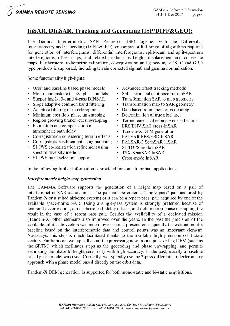
Interferometric height map generation
The GAMMA Software supports the generation of a height map based on a pair of
interferometric SAR acquisitions. The pair can be either a “single pass” pair acquired by
Tandem-X or a suited airborne system) or it can be a repeat-pass pair acquired by one of the
available space-borne SAR. Using a single-pass system is strongly preferred because of
temporal decorrelation, atmospheric path delay effects, and deformation phase corrupting the
result in the case of a repeat pass pair. Besides the availability of a dedicated mission
(Tandem-X) other elements also improved over the years. In the past the precision of the
available orbit state vectors was much lower than at present, consequently the estimation of a
baseline based on the interferometric data and control points was an important element.
Nowadays, this step is much facilitated thanks to the available high precision orbit state
vectors. Furthermore, we typically start the processing now from a pre-existing DEM (such as
the SRTM) which facilitates steps as the geocoding and phase unwrapping, and permits
estimating the phase to height sensitivity with high accuracy. In the past, usually a baseline
based phase model was used. Currently, we typically use the 2-pass differential interferometry
approach with a phase model based directly on the orbit data.
Tandem-X DEM generation is supported for both mono-static and bi-static acquisitions.

GAMMA Software Information
v1.1, 1-Dec-2017 page 5
GAMMA Remote Sensing AG, Worbstrasse 225, CH-3073 Gümligen, Switzerland tel: +41-31-951 70 05, fax: +41-31-951 70 08, email: [email protected]
Airborne DOSAR height map over
area near Solothurn (Switzerland):
SAR processing,, and InSAR using MSP and ISP. Data courtesy of
Dornier and RSL Univ. Zürich.
SIR-C, Amazon (Columbia): InSAR
height map (L-Band, vv polarization)
over a tropical forest site. InSAR processing with GAMMA ISP. SIR-C
SLC data courtesy of JPL/NASA.
ERS-1/2 Tandem, Bern
(Switzerland): Shaded relief.
Processing with GAMMA MSP, ISP, and DIFF&GEO. ERS raw
data courtesy of ESA.
TerraSAR Tandem based height
map over Mt. Etna, Italy, using. a
DINSAR approach with the SRTM 3” DEM as reference.
TDX SLC data courtesy of DLR.
Displacement mapping using DInSAR
The ISP/DIFF&GEO is designed to be very flexible with respect to separating topographic
and displacement effects. In 2-pass differential interferometry a DEM available from another
source, e.g. the SRTM DEM; is used to simulate the topographic phase that is then subtracted
from the interferogram. Other approaches, which are independent of a DEM, are 3 and 4-pass
differential interferometry. In this case an interferogram, preferably one without differential
effects, is used as reference to subtract the topographic phase effects. An option to determine
optimum phase scaling parameters based on the best fit of the reference interferogram to the
interferogram with the differential effects is included.
The differential interferometric phase relates to the line-of-sight (LOS) component of the
ground displacement. There are programs to determine the LOS direction and assuming that
the displacement is in a predefined direction (e.g. in the vertical direction, or along the surface
gradient) permits estimating the displacement in that direction. Furthermore, programs to
determine displacement vectors based on multiple observations, e.g. using acquisitions in
ascending and descending orbits are included. There are also tools included to support the
estimation and mitigation of atmospheric path delays and residual orbital phase trends. The
advanced filtering and unwrapping tools are another relevant element.
For Sentinel-1 IWS TOPS mode data co-registration and DINSAR are fully supported. For
the co-registration of Sentinel-1 IWS data refinements can be determined using matching and
using a spectral diversity method that considers double difference interferograms for the burst
overlap areas. For PALSAR-2 DINSAR using ScanSAR data is also supported. Furthermore,
ERS – ENVISAT cross-interferometry is supported.
Subsidence map over Bologna
from ERS-1 DINSAR Color scale
is 1cm/year per color cycle. ERS raw data courtesy of ESA.
TerraSAR-X ScanSAR
DINSAR over Pakistan.
Data courtesy of DLR.
PALSAR-2 ScanSAR
DINSAR over 2016 NZ
Earthquake Data courtesy of JAXA.
Co-seismic S1A-S1B
DINSAR for Italy
Earthquake 2016. S1 data courtesy ESA.
Radarsat-2 DINSAR
using multi-resolution
data. SLC data courtesy MDA, Canada.
GAMMA Software Information
v1.1, 1-Dec-2017 page 6
GAMMA Remote Sensing AG, Worbstrasse 225, CH-3073 Gümligen, Switzerland tel: +41-31-951 70 05, fax: +41-31-951 70 08, email: [email protected]
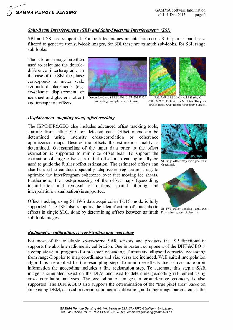
Split-Beam Interferometry (SBI) and Split-Spectrum Interferometry (SSI)
SBI and SSI are supported. For both techniques an interferometric SLC pair is band-pass
filtered to generate two sub-look images, for SBI these are azimuth sub-looks, for SSI, range
sub-looks.
The sub-look images are then
used to calculate the double-
difference interferogram. In
the case of the SBI the phase
corresponds to meter scale
azimuth displacements (e.g.
co-seismic displacement or
ice-sheet and glacier motion)
and ionospheric effects.
Devon Ice Cap , S1 SBI 20150117_20150129
indicating ionospheric effects over. PALSAR-2 SBI (left) and SSI (right)
20090619_20090804 over Mt. Etna. The phase
streaks in the SBI indicate ionospheric effects.
Displacement mapping using offset tracking
The ISP/DIFF&GEO also includes advanced offset tracking tools,
starting from either SLC or detected data. Offset maps can be
determined using intensity cross-correlation or coherence
optimization maps. Besides the offsets the estimation quality is
determined. Oversampling of the input data prior to the offset
estimation is supported to minimize offset bias. To support the
estimation of large offsets an initial offset map can optionally be
used to guide the further offset estimation. The estimated offsets can
also be used to conduct a spatially adaptive co-registration , e.g. to
optimize the interferogram coherence over fast moving ice sheets.
Furthermore, the post-processing of the offset maps (geocoding,
identification and removal of outliers, spatial filtering and
interpolation, visualization) is supported.
Offset tracking using S1 IWS data acquired in TOPS mode is fully
supported. The ISP also supports the identification of ionospheric
effects in single SLC, done by determining offsets between azimuth
sub-look images.
S1 range offset map over glaciers in
Greenland.
S1 IWS offset tracking result over Pine Island glacier Antarctica.
Radiometric calibration, co-registration and geocoding
For most of the available space-borne SAR sensors and products the ISP functionality
supports the absolute radiometric calibration. One important component of the DIFF&GEO is
a complete set of programs for precision geocoding. Terrain and ellipsoid corrected geocoding
from range-Doppler to map coordinates and vise versa are included. Well suited interpolation
algorithms are applied for the resampling step. To minimize effects due to inaccurate orbit
information the geocoding includes a fine registration step. To automate this step a SAR
image is simulated based on the DEM and used to determine geocoding refinement using
cross correlation analyses. The geocoding of images in ground-range geometry is also
supported. The DIFF&GEO also supports the determination of the “true pixel area” based on
an existing DEM, as used in terrain radiometric calibration, and other image parameters as the

GAMMA Software Information
v1.1, 1-Dec-2017 page 7
GAMMA Remote Sensing AG, Worbstrasse 225, CH-3073 Gümligen, Switzerland tel: +41-31-951 70 05, fax: +41-31-951 70 08, email: [email protected]
local incidence angle and a layover/shadow map. The DIFF&GEO also supports SLC co-
registration considering terrain topography effects.
Land Application Tools (LAT):
The land application tools support filtering, parameter extraction,
polarimetry, simple classification schemes, mosaicking, and
additional data display tools.
Filtering tools include spatial filters (moving average, median, Frost,
Lee, Enhanced Lee, Gamma Map, multi-temporal structural filter) as
well as multi-temporal filtering tools (based on Quegan et al 2001).
Data of specified polygon regions and lines can be extracted and
investigated (mean values, standard deviations, histograms).
Adaptive coherence, texture, and effective number of looks
estimation programs as well as programs to conduct simple
calculations with image data are included. Single or multiple classes
can be classified based on one or several registered input data sets
using a hierarchic thresholding scheme. Mosaicking of multiple data
sets in map geometry is supported. Tools to generate RGB and HIS
composites and tools to exchange the image intensity of one image
with that of another image are included.
Many of the filtering and classification tools of the LAT are also
very helpful for InSAR, DINSAR, and PSI, e.g. in the post-
processing (mask low quality results, condition offset maps) or to
improve certain processing steps (increase S1 co-registration
efficiency, correction of phase unwrapping errors).
RGB composite of ERS coherence
(red), average backscatter (green),
and backscatter temporal variability (blue) over the Netherlands.
Degree of polarization determined from stokes parameters calculated
based on a RSAT2 HH,HV SLC pair
Geocoding Module (GEO):
The SAR data calibration, geocoding and image co-registration functionality is also available
in the stand-alone GEO module. This module is of interest for people requiring advanced
SAR data calibration , geocoding and image co-registration functionality but without interest
in interferometric analysis. Terrain and ellipsoid corrected geocoding from range-Doppler to
map coordinates and vise versa are supported. Well suited interpolation algorithms are applied
for the resampling step. Due to inaccurate orbit information the geocoding requires a fine
registration step. In order to automate this step a SAR image is simulated (based on the DEM)
and used to automatically determine the fine registration using cross correlation analyses. The
geocoding of images in ground-range geometry and image co-registration in SAR or in map
geometry are also supported.
The functionality of the GEO is fully covered by the ISP/DIFF&GEO.

GAMMA Software Information
v1.1, 1-Dec-2017 page 8
GAMMA Remote Sensing AG, Worbstrasse 225, CH-3073 Gümligen, Switzerland tel: +41-31-951 70 05, fax: +41-31-951 70 08, email: [email protected]
Interferometric Point Target Analysis (IPTA):
The Interferometric Point Target Analysis (IPTA) supports
advanced time series analysis techniques, including Persistent
Scatterer Interferometry (PSI) and Small Baseline Subset
interferometry (SBAS). The IPTA is not a software supporting one
or a few predefined processes, but it is a “toolbox” that supports a
wide variety of approaches: using single or multi-reference stacks,
using single or multi-look interferometric phases, using point or
distributed scatterer phases, unwrapping the phase in the spatial or
temporal domain, and storing the data in vector data format or in
2D raster format.
The IPTA Module is fully compatible with the other GAMMA
software modules. Programs for conversion between the vector
data used in the IPTA and the normal 2D raster formats used are
included and the identical phase models are used. For a convenient
use of the IPTA access to the GAMMA ISP and DIFF&GEO
modules is required.
In the IPTA the user has the possibility to store the data in a vector
data format, the so-called point data stacks, which permits to
dramatically increase the processing efficiency and reduce the disk
and memory requirements. Another important element are
programs for a systematic use of the temporal dimension of the
data.
A typical IPTA processing sequence starts by co-registering
multiple repeat-pass SLCs. Then, an often used PSI approach is to
pre-select early on in the process, based on a spectral coherence
measure and the temporal variability of the backscatter, point target
candidates. In the continuation the analysis is only done for these
candidates. The physical models describing the dependence of the
interferometric phase on system and target parameters are exactly
the same as used in conventional interferometry. An iteration
concept is used for the optimization of the phase unwrapping and
information retrieval from the multi-temporal set. Parameters that
are improved include the topographic height of the scatterers, the
deformation, the atmospheric path delay, and the radar baselines.
Different phase terms can be discriminated based on its differing
spatial, temporal, and baseline dependencies. The atmospheric
phase delay, for example, is relatively smooth in the spatial
dimension, but uncorrelated in the temporal dimension. The
topographic phase shows a linear dependence on the perpendicular
baseline component and the deformation can in many cases be
assumed to be relatively smooth (or low-pass) in the spatial and
temporal dimensions.
ERS PSI example over Borth,
Germany. The average deformation
rate is shown using a color scale
between -7.5cm/year (red) and
+7.5cm/year (blue).
PALSAR-1 PSI example over
Chiba, Japan. The average deformation rate is shown using a
color scale between -2.5cm/year
(red) and +2.5cm/year (blue).
Cosmo-Skymed PSI example over
St. Moritz, Switzerland The average
deformation rate is shown using a color scale between -1.0cm/year
(red) and +1.0cm/year (blue).
GAMMA Software Information
v1.1, 1-Dec-2017 page 9
GAMMA Remote Sensing AG, Worbstrasse 225, CH-3073 Gümligen, Switzerland tel: +41-31-951 70 05, fax: +41-31-951 70 08, email: [email protected]
An advantage of using point-like targets is that they don’t show the
geometric decorrelation observed for distributed targets, permitting
to interpret interferometric phases even for pairs with baselines
above the critical baseline. Consequently, more interferometric
pairs can be included in the analysis, improving the accuracy and
temporal coverage achieved. This is particularly interesting for
sensors with rather long spatial baselines (ERS, ENVISAST,
Radarsat-1, PALSAR-1). Alternatively, using distributed targets,
multi-look phases and multi-reference stacks with short temporal
and spatial baselines are ways to optimize a the processing for
cases with very fast movements, non-uniform movements, non-
urban areas, and for relatively small data stacks.
Phase unwrapping can be done in the spatial domain (using a
minimum cost-flow algorithm) or in the temporal domain (applied
in combination with the regression analysis). The IPTA includes
functionality for the estimating the atmospheric path delay (with a
topography dependent component and a more local “turbulent
component” based on the InSAR data. Furthermore, functionality
to estimate and mitigate thermal dilation effects phases (observed
particularly for high buildings) is included.
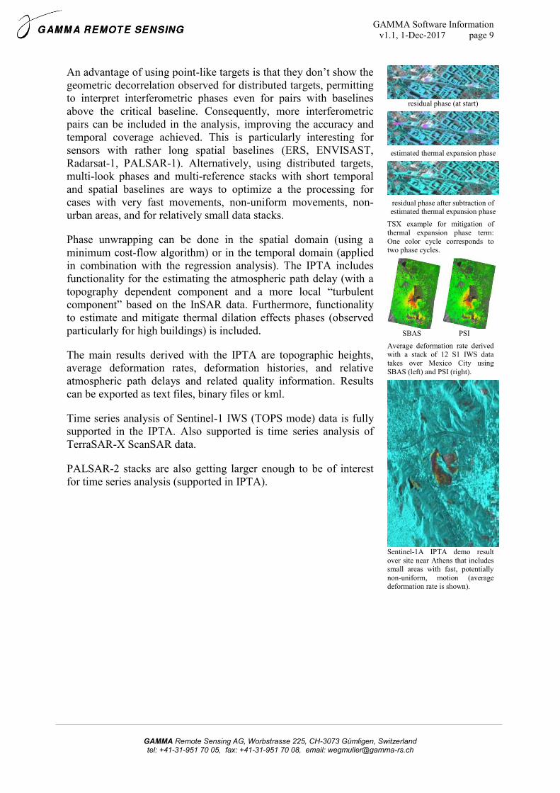
The main results derived with the IPTA are topographic heights,
average deformation rates, deformation histories, and relative
atmospheric path delays and related quality information. Results
can be exported as text files, binary files or kml.
Time series analysis of Sentinel-1 IWS (TOPS mode) data is fully
supported in the IPTA. Also supported is time series analysis of
TerraSAR-X ScanSAR data.
PALSAR-2 stacks are also getting larger enough to be of interest
for time series analysis (supported in IPTA).
residual phase (at start)
estimated thermal expansion phase
residual phase after subtraction of estimated thermal expansion phase
TSX example for mitigation of
thermal expansion phase term:
One color cycle corresponds to two phase cycles.
SBAS PSI
Average deformation rate derived with a stack of 12 S1 IWS data
takes over Mexico City using
SBAS (left) and PSI (right).
Sentinel-1A IPTA demo result
over site near Athens that includes small areas with fast, potentially
non-uniform, motion (average deformation rate is shown).

GAMMA Software Information
v1.1, 1-Dec-2017 page 10
GAMMA Remote Sensing AG, Worbstrasse 225, CH-3073 Gümligen, Switzerland tel: +41-31-951 70 05, fax: +41-31-951 70 08, email: [email protected]
3. Varia:
Further information:
Additional information. e.g. on dates and contents of GAMMA Software training courses,
is available at http://www.gamma-rs.ch.
To obtain a price list or a specific offer please contact: [email protected]
References:
There exist a number of technical reports, conference and journal papers that document a
specific element or functionality of the GAMMA Software. A list of these documents with
links to download the individual pdf files is available at:
https://www.gamma-rs.ch/uploads/media/GAMMA_Software_references.pdf.
Furthermore, upgrade information that is provided to the users with the 6 monthly an
upgrades, is also provided as pdf for download at :
https://www.gamma-rs.ch/uploads/media/GAMMA_Software_upgrade_information.pdf.
Demo examples:
Users of the GAMMA Software get access to a list of demo examples. In a demo example a
specific processing sequence is explained (e.g. S1 IWS data co-registration), input data, a
README textfile describing the processing and indicating the individual commands to use,
and some intermediate and final results (for comparison with the results generated when going
through the demo example) are provided.
At present the list of demo examples includes:
- Basic demo examples for MSP/ISP/DIFF&GEO/LAT (supporting users guide
examples)
- IPTA demo examples (ERS Borth, PALSAR Chiba, S1_Athens)
- S1 coregistration/DInSAR/tracking (Mexico_INSAR, S1_Bari_coreg
S1A_S1B_DINSAR_ItalyEarthquake, DevonIceCap, Greenland_tracking)
- S1 multi-temporal backscatter (S1_Magdeburg_multitemp)
- Tandem-X DEM generation (TDX_demo_Etna)
- PALSAR-2 cross-mode and multi-resolution DInSAR
Recent developments:
- ALOS PALSAR ScanSAR data processing and interferometry
- RISAT, KOMPSAT-5, Gaofen-3 adaptations
- PALSAR-2 and TSX ScanSAR interferometry
- Sentinel-1 (S1A/S1B) adaptations
- Multi-baseline time-series analysis
- Enhanced offset-tracking functionality
- S1 TOPS mode data support (from SLC)
- Split-beam and split-spectrum interferometry support
- Identification of ionospheric effects
- RSAT-2, PALSAR-2, S1 cross-mode interferometry
- Interpolation and resampling methods were improved.