gamcorp (melbourne) pty ltd a.c.n 141 076 ... - impact solar€¦ · roof flush mount solar system...
TRANSCRIPT

Gamcorp (Melbourne) Pty Ltd A.C.N 141 076 904 A.B.N 73 015 060 240www.gamcorp.com.au Email: [email protected] 4, 346 Ferntree Gully Rd, Notting Hill VIC 3149. Tel: 03 9543 2211 Fax: 03 9543 4046
Our Ref: 2242/K.Z
28 July 2016
Xiamen Hopergy Photovoltaic Technology Co. Ltd.No.630, Tonghong RoadTongan District, Xiamen 361100China
PV Array Frame Engineering Certification
Installation of Hopergy Tin Roof Flush Mount Solar System with HOP-SLR02 Rails
Gamcorp (Melbourne) Pty Ltd, being Structural Engineers within the meaning of Australian andNew Zealand Building Regulations, have carried out a structural design check of Hopergy Tin Roof Flush Mount Solar System installation within Australia and New Zealand. The design check has been based on the information in the schematic drawings of the system components provided by Hopergy Australia (IMSOLAR).
We find the Installation of Hopergy Tin Roof Flush Mount Solar System for Australian and New Zealand use to be structurally sufficient based on the following conditions:
• Wind loads to AS/NZ1170.2:2011 Admt 3-2013• Wind region A, B, C, D, W• Wind terrain category 2 & 3• Wind average recurrence interval of 500 years• Maximum building height 20m• The PV panel dimensions to be 1640mm x 992mm and 2000mm x 1000mm• Maximum weight of the PV panel and array frame to be 15 kg/m2
• Rails to be HOP-SLR02• The tin roof interface to be L-feet bracket or T-feet bracket as per drawing HOP-TRB01-
38• The assessment is based on an assumption that the interface brackets meet the
industrial standard requirements• Each PV panel to be installed using 2 rails minimum in all circumstances• Installation of PV array to be done in accordance with the PV installation manual• The certification excludes assessment of roof structure and PV panels
Refer to attached summary table for interface spacing
NOTES:• The recommended spacing nominated in this certification is based on the
capacity of the array frame, not the roof structure and PV panel. It is the responsibility of the installer to adopt the most critical spacing.
• This is the up-to-date certification. All previous certifications for Hopergy
Page 1 of 2ISO 9001:2008 Registered Firm
Certificate No: AU1222
Gamcorp (Melbourne) Pty Ltd A.C.N 141 076 904 A.B.N 73 015 060 240www.gamcorp.com.au Email: [email protected] 4, 346 Ferntree Gully Rd, Notting Hill VIC 3149. Tel: 03 9543 2211 Fax: 03 9543 4046
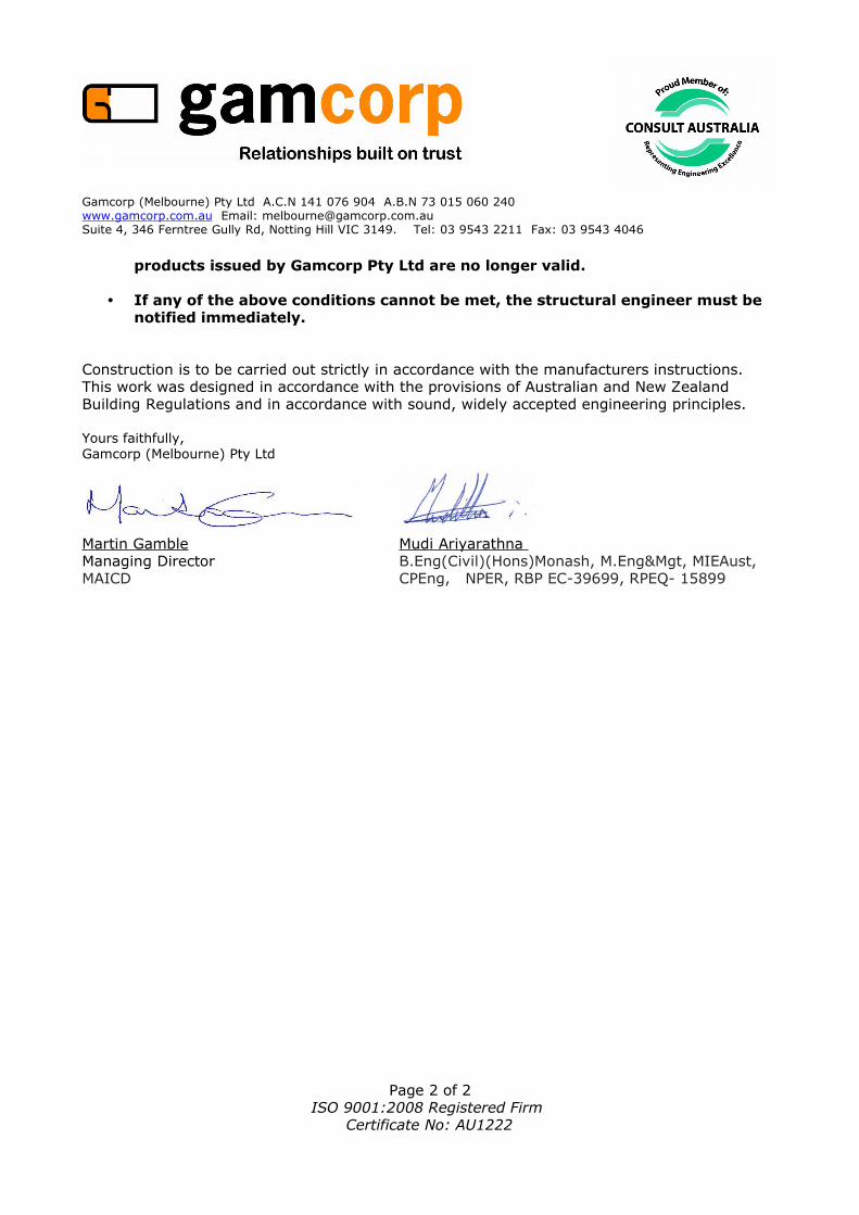
products issued by Gamcorp Pty Ltd are no longer valid.
• If any of the above conditions cannot be met, the structural engineer must be notified immediately.
Construction is to be carried out strictly in accordance with the manufacturers instructions. This work was designed in accordance with the provisions of Australian and New Zealand Building Regulations and in accordance with sound, widely accepted engineering principles.
Yours faithfully,Gamcorp (Melbourne) Pty Ltd
Martin Gamble Mudi Ariyarathna Managing Director B.Eng(Civil)(Hons)Monash, M.Eng&Mgt, MIEAust, MAICD CPEng, NPER, RBP EC-39699, RPEQ- 15899
Page 2 of 2ISO 9001:2008 Registered Firm
Certificate No: AU1222
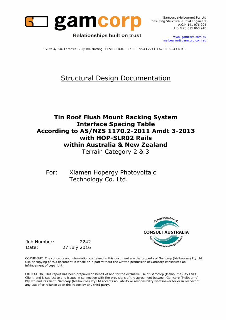
For: Xiamen Hopergy PhotovoltaicTechnology Co. Ltd.
Job Number: 2242
Date: 27 July 2016
Structural Design Documentation
Interface Spacing TableAccording to AS/NZS 1170.2-2011 Amdt 3-2013
with HOP-SLR02 Railswithin Australia & New Zealand
Terrain Category 2 & 3
Tin Roof Flush Mount Racking System
Gamcorp (Melbourne) Pty Ltd
Consulting Structural & Civil Engineers
A.C.N 141 076 904
A.B.N 73 015 060 240
www.gamcorp.com.au
Suite 4/ 346 Ferntree Gully Rd, Notting Hill VIC 3168. Tel: 03 9543 2211 Fax: 03 9543 4046
COPYRIGHT: The concepts and information contained in this document are the property of Gamcorp (Melbourne) Pty Ltd. Use or copying of this document in whole or in part without the written permission of Gamcorp constitutes an infringement of copyright.
LIMITATION: This report has been prepared on behalf of and for the exclusive use of Gamcorp (Melbourne) Pty Ltd’s Client, and is subject to and issued in connection with the provisions of the agreement between Gamcorp (Melbourne) Pty Ltd and its Client. Gamcorp (Melbourne) Pty Ltd accepts no liability or responsibility whatsoever for or in respect of any use of or reliance upon this report by any third party.

Client Name
Job No:
Client: Xiamen Hopergy Photovoltaic Technology Co. Ltd.
Project: Flush Mount Interface Spacing Table for Tin Roof
Address:
Australian/New Zealand Standards
AS/NZS 1170. 2011 – Structural Design Actions
Part 0 – General Principles
Part 1 – Permanent imposed and other actions
Part 2 – Wind Actions
Part 3 – Snow and Ice Actions
AS/NZS 1252 – High Strength Structural Bolting
AS 4055 – Wind Loads for HousingAS 4100 – Steel StructuresAS/NZS 4600 – Cold-Formed Steel Structures
WTC 2 & 3
2242
Date: Jul-16
within Australia & New Zealand
Wind Terrain Category:
Designed: K.Z
Suite 4/ 346 Ferntree Gully Rd Notting Hill VIC 3168
Tel: 03 9543 2211
Fax: 03 9543 4046
www.gamcorp.com.au
ISO 9001:2008 Registered Firm
Certificate No: AU1222

Client: Xiamen Hopergy Photovoltaic Technology Co. Ltd. Job:
Project: Flush Mount Interface Spacing Table for Tin Roof Date:
Address:
Designed: Checked: M.A
Flush Mount Interface Spacing Table for Tin Roof
Type of Rail HOP-SLR02
Type of Interface Tin Interface Bracket
Solar Panel Dimension 1.64m x 0.99m
Terrain category 2
Roof Angle (Φ) – 5° - 10°
D.W &
U.W Central D.W & U.W Central D.W & U.W Central
A 1399 1529 1362 1487 1341 1464
B 1232 1341 1201 1307 1183 1287
C 1111 1207 1083 1177 1068 1160
D 985 1069 961 1043 947 1028
W 1307 1425 1273 1388 1255 1366
Roof Angle (Φ) – 10° - 20°
D.W &
U.W Central D.W & U.W Central D.W & U.W Central
A 1310 1436 1277 1398 1258 1377
B 1156 1263 1127 1231 1111 1213
C 1044 1139 1018 1110 1003 1094
D 926 1009 904 984 891 970
W 1226 1341 1195 1306 1177 1287
D.W & U.W – Downwind and Upwind refer to note 6.
Wind
Region
Building Height – H (m)
H≤10 10<H≤15 15<H≤20
Wind
Region
Building Height – H (m)
H≤10 10<H≤15 15<H≤20
2242
Jul-16
within Australia & New Zealand
K.Z
ISO 9001:2008 Registered Firm
Certificate No: AU1222 Page 1 of 10
Client: Xiamen Hopergy Photovoltaic Technology Co. Ltd. Job:
Project: Flush Mount Interface Spacing Table for Tin Roof Date:
Address:
Designed: Checked: M.A
2242
Jul-16
within Australia & New Zealand
K.Z
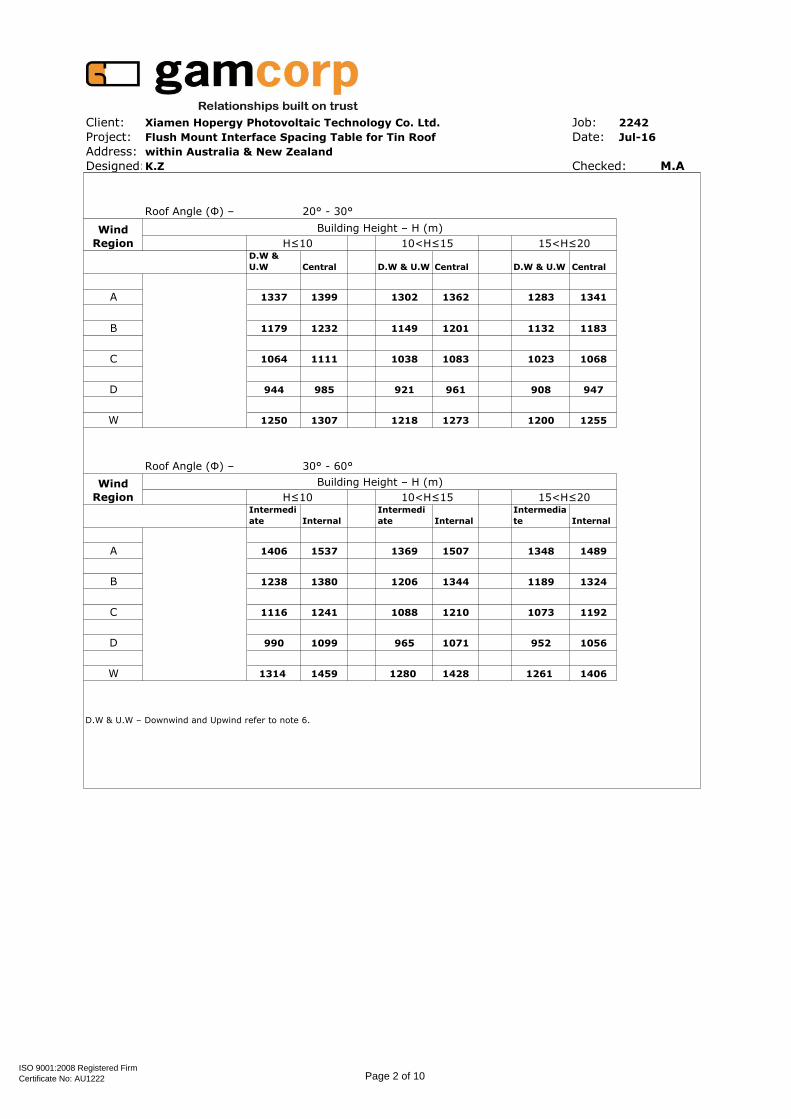
Roof Angle (Φ) – 20° - 30°
D.W &
U.W Central D.W & U.W Central D.W & U.W Central
A 1337 1399 1302 1362 1283 1341
B 1179 1232 1149 1201 1132 1183
C 1064 1111 1038 1083 1023 1068
D 944 985 921 961 908 947
W 1250 1307 1218 1273 1200 1255
Roof Angle (Φ) – 30° - 60°
Intermedi
ate Internal
Intermedi
ate Internal
Intermedia
te Internal
A 1406 1537 1369 1507 1348 1489
B 1238 1380 1206 1344 1189 1324
C 1116 1241 1088 1210 1073 1192
D 990 1099 965 1071 952 1056
W 1314 1459 1280 1428 1261 1406
D.W & U.W – Downwind and Upwind refer to note 6.
Building Height – H (m)Wind
Region
Building Height – H (m)Wind
Region
10<H≤15H≤10 15<H≤20
H≤10 10<H≤15 15<H≤20
ISO 9001:2008 Registered Firm
Certificate No: AU1222 Page 2 of 10

Client: Xiamen Hopergy Photovoltaic Technology Co. Ltd. Job:
Project: Flush Mount Interface Spacing Table for Tin Roof Date:
Address:
Designed: Checked: M.A
2242
Jul-16
within Australia & New Zealand
K.Z
Flush Mount Interface Spacing Table for Tin Roof
Type of Rail HOP-SLR02
Type of Interface Tin Interface Bracket
Solar Panel Dimension 1.64m x 0.99m
Terrain category 3
Roof Angle (Φ) – 5° - 10°
D.W &
U.W Central D.W & U.W Central D.W & U.W Central
A 1553 1705 1492 1635 1447 1584
B 1361 1486 1311 1429 1273 1387
C 1225 1333 1181 1284 1147 1247
D 1084 1178 1046 1136 1017 1104
W 1447 1583 1392 1521 1351 1475
Roof Angle (Φ) – 10° - 20°
D.W &
U.W Central D.W & U.W Central D.W & U.W Central
A 1451 1596 1396 1533 1355 1486
B 1276 1397 1229 1345 1194 1306
C 1150 1256 1109 1211 1078 1176
D 1019 1111 983 1072 956 1042
W 1354 1486 1304 1429 1267 1387
Wind
Region
H≤10 10<H≤15 15<H≤20
D.W & U.W – Downwind and Upwind refer to note 6.
Building Height – H (m)
H≤10 10<H≤15 15<H≤20
Wind
Region
Building Height – H (m)
ISO 9001:2008 Registered Firm
Certificate No: AU1222 Page 3 of 10

Client: Xiamen Hopergy Photovoltaic Technology Co. Ltd. Job:
Project: Flush Mount Interface Spacing Table for Tin Roof Date:
Address:
Designed: Checked: M.A
2242
Jul-16
within Australia & New Zealand
K.Z
Roof Angle (Φ) – 20° - 30°
D.W &
U.W Central D.W & U.W Central D.W & U.W Central
A 1481 1553 1424 1492 1382 1447
B 1301 1361 1254 1311 1218 1273
C 1172 1225 1130 1181 1099 1147
D 1038 1084 1002 1046 974 1017
W 1382 1447 1331 1392 1292 1351
Roof Angle (Φ) – 30° - 60°
Intermedi
ate Internal
Intermedi
ate Internal
Intermedia
te Internal
A 1527 1653 1483 1610 1450 1576
B 1368 1506 1317 1462 1279 1428
C 1231 1372 1186 1321 1153 1283
D 1089 1211 1051 1167 1022 1134
W 1449 1575 1399 1532 1358 1498
D.W & U.W – Downwind and Upwind refer to note 6.
H≤10 10<H≤15 15<H≤20
Wind
Region
Building Height – H (m)
Wind
Region
Building Height – H (m)
H≤10 10<H≤15 15<H≤20
ISO 9001:2008 Registered Firm
Certificate No: AU1222 Page 4 of 10
Client: Xiamen Hopergy Photovoltaic Technology Co. Ltd. Job:
Project: Flush Mount Interface Spacing Table for Tin Roof Date:
Address:
Designed: Checked: M.A
2242
Jul-16
within Australia & New Zealand
K.Z
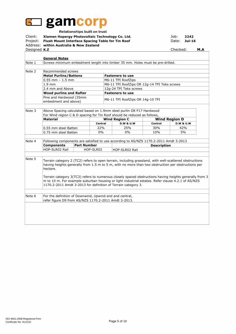
General Notes
Note 1 Screws minimum embedment length into timber 35 mm. Holes must be pre-drilled.
Note 2 Recommended screws
Note 3 Above Spacing calculated based on 1.9mm steel purlin OR F17 Hardwood
For Wind region C & D spacing for Tin Roof should be reduced as follows,
0.55 mm steel Batten
0.75 mm steel Batten
Note 4 Following components are satisfied to use according to AS/NZS 1170.2-2011 Amdt 3-2013
Note 5
Note 6 For the definition of Downwind, Upwind end and central,
refer figure D9 from AS/NZS 1170.2-2011 Amdt 3-2013.
D.W & U.W
Metal Purlins/Battens Fasteners to use
0.55 mm – 1.5 mm M6-11 TPI RoofZips
1.9 mm M6-11 TPI RoofZips OR 12g-14 TPI Teks screws
2.4 mm and Above 12g-24 TPI Teks screws
Terrain category 2 (TC2) refers to open terrain, including grassland, with well-scattered obstructions
having heights generally from 1.5 m to 5 m, with no more than two obstruction per obstructions per
hectare.
Terrain category 3(TC3) refers to numerous closely spaced obstructions having heights generally from 3
m to 10 m. For example suburban housing or light industrial estates. Refer clause 4.2.1 of AS/NZS
1170.2-2011 Amdt 3-2013 for definition of Terrain category 3.
0% 0% 10% 5%
Components Part Number
HOP-SLR02 Rail HOP-SLR02 HOP-SLR02 Rail
Description
25% 30%
Wood purlins and Rafter Fasteners to use
Pine and Hardwood (35mm
embedment and above)M6-11 TPI RoofZips OR 14g-10 TPI
Material Wind Region C Wind Region D
42%
Central D.W & U.W Central
22%
ISO 9001:2008 Registered Firm
Certificate No: AU1222 Page 5 of 10

Client: Xiamen Hopergy Photovoltaic Technology Co. Ltd. Job:
Project: Flush Mount Interface Spacing Table for Tin Roof Date:
Address:
Designed: Checked: M.A
Flush Mount Interface Spacing Table for Tin Roof
Type of Rail HOP-SLR02
Type of Interface Tin Interface Bracket
Solar Panel Dimension 2m x 1m
Terrain category 2
Roof Angle (Φ) – 5° - 10°
D.W &
U.W Central D.W & U.W Central D.W & U.W Central
A 1331 1455 1296 1415 1277 1393
B 1172 1276 1143 1243 1126 1225
C 1057 1149 1031 1120 1016 1103
D 937 1017 914 992 901 978
W 1244 1356 1212 1320 1194 1300
Roof Angle (Φ) – 10° - 20°
D.W &
U.W Central D.W & U.W Central D.W & U.W Central
A 1247 1367 1215 1330 1197 1310
B 1100 1202 1073 1172 1057 1154
C 993 1084 969 1057 955 1041
D 881 961 860 937 848 923
W 1167 1276 1137 1243 1120 1224
D.W & U.W – Downwind and Upwind refer to note 6.
Wind
Region
Building Height – H (m)
H≤10 10<H≤15
Wind
Region
Building Height – H (m)
H≤10 10<H≤15 15<H≤20
2242
Jul-16
within Australia & New Zealand
K.Z
15<H≤20
ISO 9001:2008 Registered Firm
Certificate No: AU1222 Page 6 of 10

Client: Xiamen Hopergy Photovoltaic Technology Co. Ltd. Job:
Project: Flush Mount Interface Spacing Table for Tin Roof Date:
Address:
Designed: Checked: M.A
2242
Jul-16
within Australia & New Zealand
K.Z
Roof Angle (Φ) – 20° - 30°
D.W &
U.W Central D.W & U.W Central D.W & U.W Central
A 1272 1331 1239 1296 1221 1277
B 1122 1172 1094 1143 1078 1126
C 1012 1057 987 1031 973 1016
D 898 937 876 914 864 901
W 1190 1244 1159 1212 1142 1194
Roof Angle (Φ) – 30° - 60°
Intermedi
ate Internal
Intermedi
ate Internal
Intermedia
te Internal
A 1338 1463 1303 1434 1283 1417
B 1178 1313 1148 1279 1131 1260
C 1062 1181 1036 1151 1021 1134
D 942 1045 919 1019 905 1005
W 1250 1389 1218 1359 1200 1338
Building Height – H (m)Wind
Region
Building Height – H (m)Wind
Region
10<H≤15H≤10 15<H≤20
H≤10 10<H≤15 15<H≤20
D.W & U.W – Downwind and Upwind refer to note 6.
ISO 9001:2008 Registered Firm
Certificate No: AU1222 Page 7 of 10
Client: Xiamen Hopergy Photovoltaic Technology Co. Ltd. Job:
Project: Flush Mount Interface Spacing Table for Tin Roof Date:
Address:
Designed: Checked: M.A
2242
Jul-16
within Australia & New Zealand
K.Z
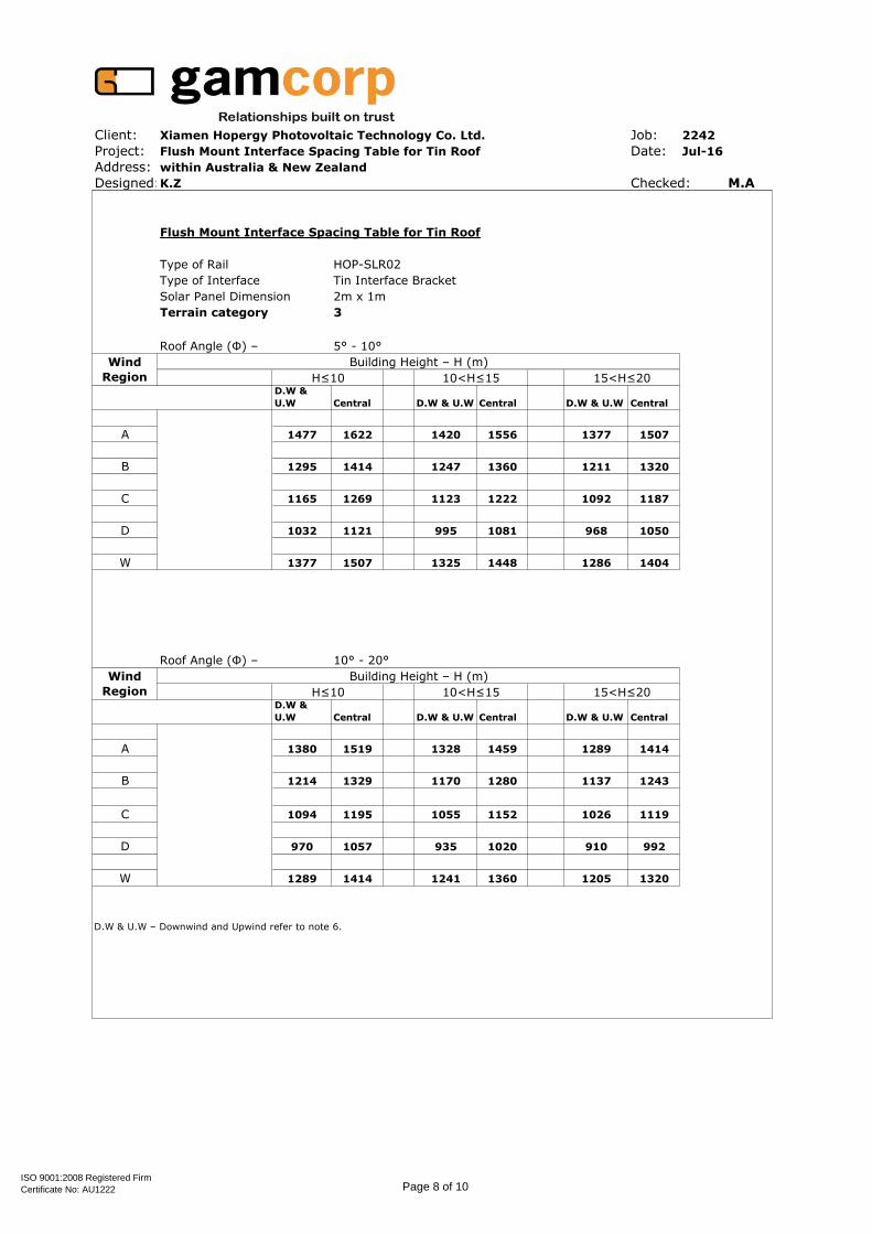
Flush Mount Interface Spacing Table for Tin Roof
Type of Rail HOP-SLR02
Type of Interface Tin Interface Bracket
Solar Panel Dimension 2m x 1m
Terrain category 3
Roof Angle (Φ) – 5° - 10°
D.W &
U.W Central D.W & U.W Central D.W & U.W Central
A 1477 1622 1420 1556 1377 1507
B 1295 1414 1247 1360 1211 1320
C 1165 1269 1123 1222 1092 1187
D 1032 1121 995 1081 968 1050
W 1377 1507 1325 1448 1286 1404
Roof Angle (Φ) – 10° - 20°
D.W &
U.W Central D.W & U.W Central D.W & U.W Central
A 1380 1519 1328 1459 1289 1414
B 1214 1329 1170 1280 1137 1243
C 1094 1195 1055 1152 1026 1119
D 970 1057 935 1020 910 992
W 1289 1414 1241 1360 1205 1320
Wind
Region
Building Height – H (m)
Wind
Region
H≤10 10<H≤15 15<H≤20
D.W & U.W – Downwind and Upwind refer to note 6.
Building Height – H (m)
H≤10 10<H≤15 15<H≤20
ISO 9001:2008 Registered Firm
Certificate No: AU1222 Page 8 of 10

Client: Xiamen Hopergy Photovoltaic Technology Co. Ltd. Job:
Project: Flush Mount Interface Spacing Table for Tin Roof Date:
Address:
Designed: Checked: M.A
2242
Jul-16
within Australia & New Zealand
K.Z
Roof Angle (Φ) – 20° - 30°
D.W &
U.W Central D.W & U.W Central D.W & U.W Central
A 1409 1477 1356 1420 1315 1377
B 1238 1295 1193 1247 1159 1211
C 1115 1165 1075 1123 1045 1092
D 988 1032 953 995 927 968
W 1315 1377 1266 1325 1230 1286
Roof Angle (Φ) – 30° - 60°
Intermedi
ate Internal
Intermedi
ate Internal
Intermedia
te Internal
A 1453 1573 1412 1532 1379 1500
B 1302 1433 1254 1392 1217 1359
C 1171 1306 1129 1257 1097 1221
D 1037 1152 1000 1111 972 1080
W 1379 1499 1332 1458 1292 1425
D.W & U.W – Downwind and Upwind refer to note 6.
H≤10 10<H≤15 15<H≤20
Building Height – H (m)
H≤10 10<H≤15 15<H≤20
Wind
Region
Wind
Region
Building Height – H (m)
ISO 9001:2008 Registered Firm
Certificate No: AU1222 Page 9 of 10

Client: Xiamen Hopergy Photovoltaic Technology Co. Ltd. Job:
Project: Flush Mount Interface Spacing Table for Tin Roof Date:
Address:
Designed: Checked: M.A
2242
Jul-16
within Australia & New Zealand
K.Z
General Notes
Note 1 Screws minimum embedment length into timber 35 mm. Holes must be pre-drilled.
Note 2 Recommended screws
Note 3 Above Spacing calculated based on 1.9mm steel purlin OR F17 Hardwood
For Wind region C & D spacing for Tin Roof should be reduced as follows,
0.55 mm steel Batten
0.75 mm steel Batten
Note 4 Following components are satisfied to use according to AS/NZS 1170.2-2011 Amdt 3-2013
Note 5
Note 6 For the definition of Downwind, Upwind end and central,
refer figure D9 from AS/NZS 1170.2-2011 Amdt 3-2013.
22% 25% 30%
Wood purlins and Rafter Fasteners to use
Pine and Hardwood (35mm
embedment and above)M6-11 TPI RoofZips OR 14g-10 TPI
Material Wind Region C Wind Region D
42%
Central D.W & U.W
Terrain category 2 (TC2) refers to open terrain, including grassland, with well-scattered obstructions
having heights generally from 1.5 m to 5 m, with no more than two obstruction per obstructions per
hectare.
Terrain category 3(TC3) refers to numerous closely spaced obstructions having heights generally from 3
m to 10 m. For example suburban housing or light industrial estates. Refer clause 4.2.1 of AS/NZS
1170.2-2011 Amdt 3-2013 for definition of Terrain category 3.
0% 0% 10% 5%
Components Part Number
HOP-SLR02 Rail HOP-SLR02 HOP-SLR02 Rail
Description
D.W & U.W
Metal Purlins/Battens Fasteners to use
0.55 mm – 1.5 mm M6-11 TPI RoofZips
1.9 mm M6-11 TPI RoofZips OR 12g-14 TPI Teks screws
2.4 mm and Above 12g-24 TPI Teks screws
Central
ISO 9001:2008 Registered Firm
Certificate No: AU1222 Page 10 of 10