galileo 5 ghz signal characteristics - international civil ... · web viewinternational civil...
TRANSCRIPT

International Civil Aviation Organization
INFORMATION PAPER
ACP-WGF20/IP-0311/03/09
AERONAUTICAL COMMUNICATIONS PANEL (ACP)
20TH MEETING OF WORKING GROUP F
Montreal, Canada 24 March – 3 April 2009
Agenda Item 5: Development of material for ITU-R meetings
Galileo 5 GHz Signal Characteristics
(Presented by John Mettrop)
SUMMARY
This paper copies a paper provided by the European Commission to the recent PT-C meeting on characteristics of the 5 GHz components of the Galileo RNSS.
ACTION
To note the paper and take the information into consideration when preparing any working papers with respect to WRC-11 Agenda Item 1.4 Resolution 420.
1. INTRODUCTION
1.1 At the 2007 World Radiocommunications Conference a number of frequency bands were proposed as solutions for Agenda item 1.6. Two of those frequency bands were 5 000-5 010 MHz and 5 010-5 030 MHz. Whilst no allocation was made at the conference in these bands, the proposals were carried forward to WRC-11 as part of agenda item 1.4 of that conference under Resolution 420.
2. DISCUSSION
2.1 Resolution 420 calls for administrations as well as ICAO to provide technical and operational characteristics of AM(R)S and RNSS necessary for carrying out compatibility studies and to actively participate in those studies. At a recent PT-C meeting the European Commission contributed the attached paper which provides the characteristics of the elements of the Galileo system designed to
(24 pages) document.doc
ACP-WGF20/IP-03
operate in the frequency band 5 010-5 030 MHz it is copied here to aid in any proposed aeronautical studies.
3. ACTION BY THE MEETING
3.1 The ACP WGF is invited to note the information provided and, where appropriate, use the information in preparing contributions to regional and global meetings with respect to WRC-11 Agenda item 1.4 Resolution 420.
2

ACP-WGF20/IP-03
Attachment 1
3
ACP-WGF20/IP-03
Radiocommunication Study Groups
Source: Annex 5 to Document 4C/146
Subject: PDNR ITU-R M.[S-E RX+TX]
Reference:
10 March 2009English only
PRELIMINARY DRAFT NEW RECOMMENDATION ITU-R M.[S-E RX+TX]
Characteristics and protection criteria of receiving earth stations and characteristics of transmitting space stations of the radionavigation-
satellite service (space-to-Earth) operating in the band 5 010-5 030 MHz
(Questions ITU-R 217-2/8 and ITU-R 236-2/8)
ScopeCharacteristics and protection criteria for radionavigation-satellite service (RNSS) receiving earth stations and characteristics of RNSS transmitting space stations planned or operating in the band 5 010-5 030 MHz are presented in this Recommendation. This information is intended for use in assessing the interference impact on systems and networks in the RNSS (space-to-Earth) operating in the band 5 010-5 030 MHz from radio sources other than in the RNSS.
The ITU Radiocommunication Assembly,
consideringa) that systems and networks in the RNSS provide global and accurate positioning and timing for many applications, [including crucial ones related to safety of life];b) that there are various operating and planned systems and networks in the RNSS;c) that there are studies being conducted or planned on the impact to RNSS networks and systems from other services and systems (ARNS, etc.); [d) that Recommendation ITU-R M.[RNSS_Org] provides the organization, application, and terminology of ITU-R RNSS Recommendations providing technical characteristics and protection criteria for the RNSS;]
4
ACP-WGF20/IP-03
[e) that Recommendation ITU-R M.[E-S Tx+Rx] provides the characteristics and protection criteria for RNSS systems operating in the band 5 000-5 010 MHz,]
5
ACP-WGF20/IP-03
recognizing[a) that the band 5 010-5 030 MHz is allocated on a primary basis to RNSS (space-to-Earth and space-to-space) in all three Regions;b) that the band 5 010-5 030 MHz is also allocated on a primary basis to the aeronautical radionavigation service (ARNS) in all three Regions;c) that the band 5 010-5 030 MHz is also allocated on a primary basis to the aeronautical mobile-satellite (R) service (AMS(R)S) in all three Regions subject to No. 9.21 of the Radio Regulations (RR);d) that, under RR No. 5.328B, systems and networks in the RNSS intending to use the bands 1 164-1 215 MHz, 1 215-1 300 MHz, 1 559-1 610 MHz and 5 010-5 030 MHz for which complete coordination or notification information, as appropriate, is received by the Radiocommunication Bureau after 1 January 2005 are subject to the application of the provisions of RR Nos. 9.12, 9.12A and 9.13, and studies to determine additional methodologies and criteria to facilitate such coordination are being planned;e) that, under RR No. 9.7, stations in satellite networks in the RNSS using the geostationary-satellite orbit are subject to coordination with other such satellite networks, and studies to determine additional methodologies and criteria to facilitate such coordination are being planned;f) that RR No. 5.443B and Resolution 741 (WRC-03) provide aggregate power flux-density limits on space stations in the RNSS to prevent harmful interference to the radio astronomy service (RAS) operating in the band 4 990-5 000 MHz;g) that RR No. 5.443B provides aggregate power flux-density limits on space stations in the RNSS to prevent harmful interference to the microwave landing system which operates in the aeronautical radionavigation service (ARNS) above 5 030 MHz,]
recommends1 that the characteristics and protection criteria of receiving earth stations and the characteristics of transmitting space stations given in Annexes 1, 2 and 3 should be used in performing analyses of the interference impact on systems and networks in the RNSS (space-to-Earth) operating in the band 5 010-5 030 MHz from radio sources other than in the RNSS.{Editor’s Note: The following Annexes require updating to align them with the parameter Tables in M.[RNSS_Org] at least for service links, or remove the reference to M.[s-E Rx+Tx] from the title of Table 3 of M.[RNSS_Org]}
6

ACP-WGF20/IP-03
Annex 1
Typical technical characteristics and protection criteria for Galileo receiving earth stations operating in the band 5 010-5 030 MHz
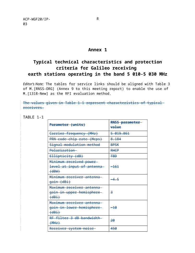
Editor’s Note: The tables for service links should be aligned with Table 3 of M.[RNSS-ORG] (Annex 9 to this meeting report) to enable the use of M.[1318-New] as the RFI evaluation method.
The values given in Table 1-1 represent characteristics of typical receivers.
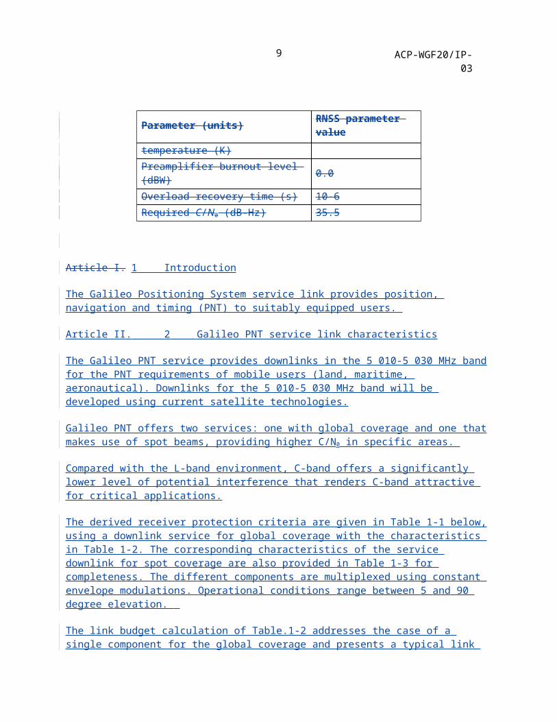
TABLE 1-1Parameter (units) RNSS parameter valueCarrier frequency (MHz) 5 019.861PRN code chip rate (Mcps) 8.184Signal modulation method BPSKPolarization RHCPEllipticity (dB) TBDMinimum received power level at input of antenna (dBW) −161
Minimum receiver antenna gain (dBi) −4.5Maximum receiver antenna gain in upper hemisphere (dBi) 3
Maximum receiver antenna gain in lower hemisphere (dBi) −10
RF filter 3 dB bandwidth (MHz) 20Receiver system noise temperature (K) 450Preamplifier burnout level (dBW) 0.0Overload recovery time (s) 10-6Required C/N0 (dB-Hz) 35.5
Article I. 1 Introduction
The Galileo Positioning System service link provides position, navigation and timing (PNT) to suitably equipped users.
Article II. 2 Galileo PNT service link characteristics
The Galileo PNT service provides downlinks in the 5 010-5 030 MHz band for the PNT requirements of mobile users (land, maritime, aeronautical). Downlinks for the 5 010-5 030 MHz band will be developed using current satellite technologies.
7
ACP-WGF20/IP-03
Galileo PNT offers two services: one with global coverage and one that makes use of spot beams, providing higher C/N0 in specific areas.
Compared with the L-band environment, C-band offers a significantly lower level of potential interference that renders C-band attractive for critical applications.
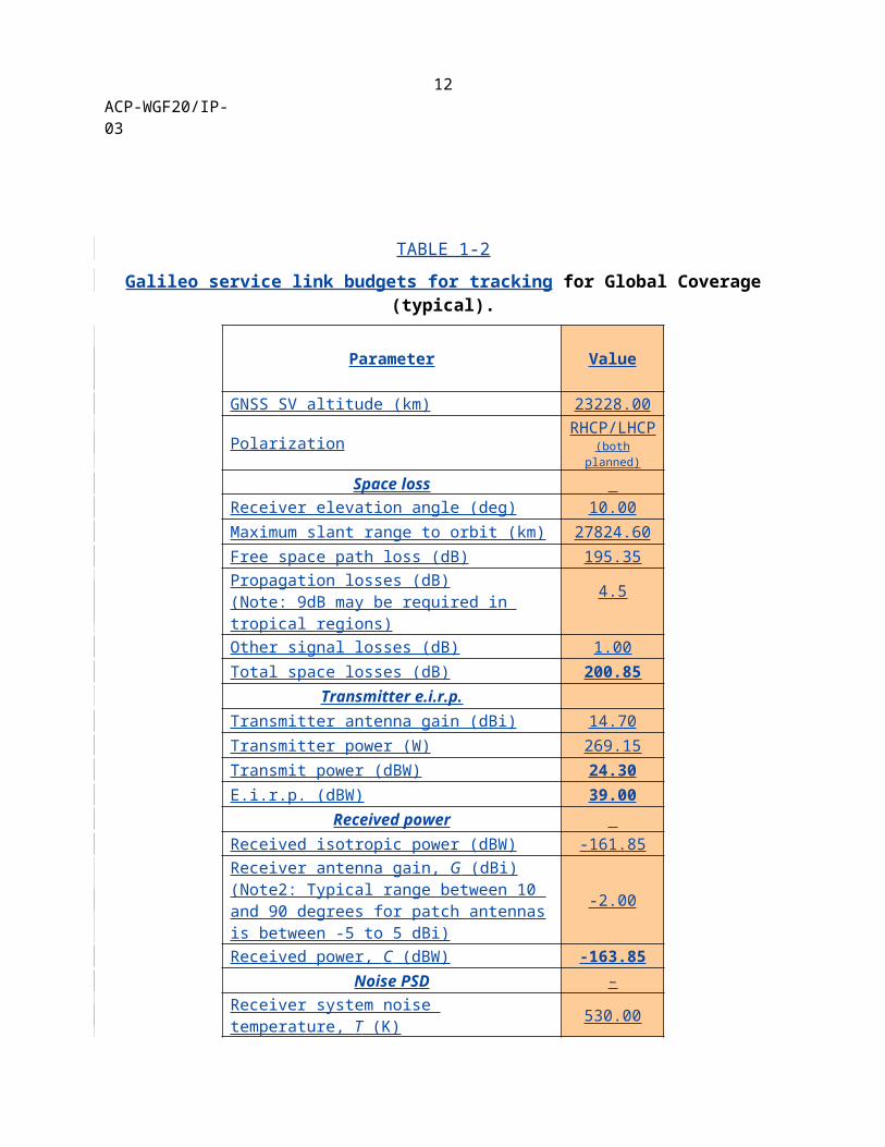
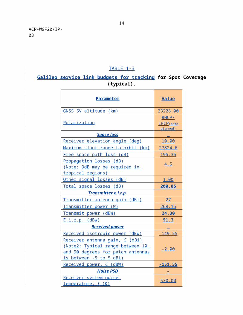
The derived receiver protection criteria are given in Table 1-1 below, using a downlink service for global coverage with the characteristics in Table 1-2. The corresponding characteristics of the service downlink for spot coverage are also provided in Table 1-3 for completeness. The different components are multiplexed using constant envelope modulations. Operational conditions range between 5 and 90 degree elevation.
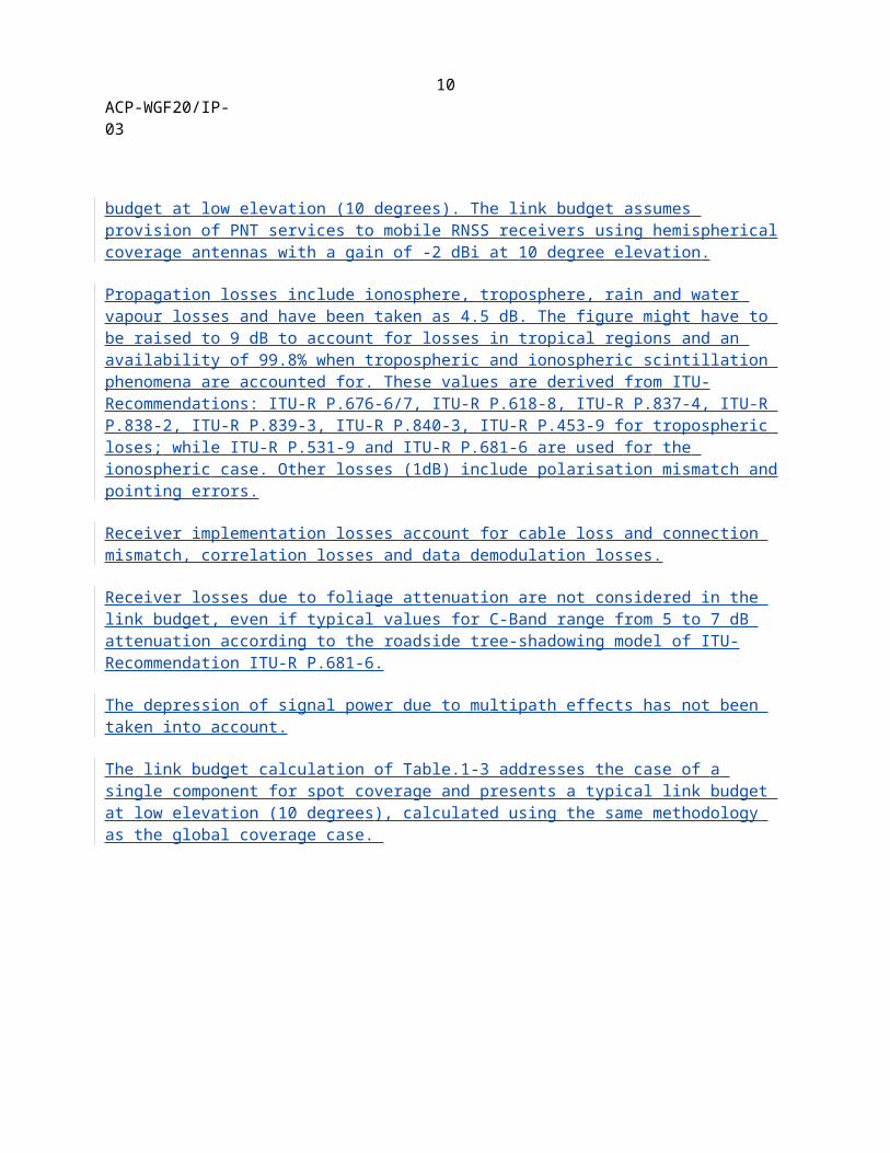
The link budget calculation of Table.1-2 addresses the case of a single component for the global coverage and presents a typical link budget at low elevation (10 degrees). The link budget assumes provision of PNT services to mobile RNSS receivers using hemispherical coverage antennas with a gain of -2 dBi at 10 degree elevation.
Propagation losses include ionosphere, troposphere, rain and water vapour losses and have been taken as 4.5 dB. The figure might have to be raised to 9 dB to account for losses in tropical regions and an availability of 99.8% when tropospheric and ionospheric scintillation phenomena are accounted for. These values are derived from ITU-Recommendations: ITU-R P.676-6/7, ITU-R P.618-8, ITU-R P.837-4, ITU-R P.838-2, ITU-R P.839-3, ITU-R P.840-3, ITU-R P.453-9 for tropospheric loses; while ITU-R P.531-9 and ITU-R P.681-6 are used for the ionospheric case. Other losses (1dB) include polarisation mismatch and pointing errors.
Receiver implementation losses account for cable loss and connection mismatch, correlation losses and data demodulation losses.
Receiver losses due to foliage attenuation are not considered in the link budget, even if typical values for C-Band range from 5 to 7 dB attenuation according to the roadside tree-shadowing model of ITU-Recommendation ITU-R P.681-6.
The depression of signal power due to multipath effects has not been taken into account.
The link budget calculation of Table.1-3 addresses the case of a single component for spot coverage and presents a typical link budget at low elevation (10 degrees), calculated using the same methodology as the global coverage case.
8
ACP-WGF20/IP-03
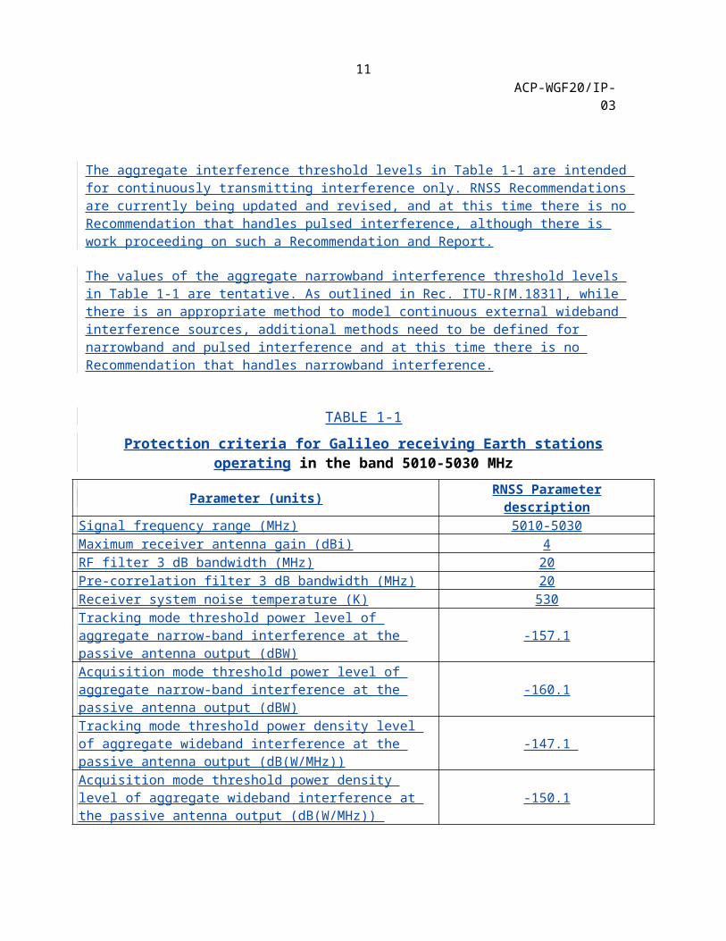
The aggregate interference threshold levels in Table 1-1 are intended for continuously transmitting interference only. RNSS Recommendations are currently being updated and revised, and at this time there is no Recommendation that handles pulsed interference, although there is work proceeding on such a Recommendation and Report.
The values of the aggregate narrowband interference threshold levels in Table 1-1 are tentative. As outlined in Rec. ITU-R[M.1831], while there is an appropriate method to model continuous external wideband interference sources, additional methods need to be defined for narrowband and pulsed interference and at this time there is no Recommendation that handles narrowband interference.
TABLE 1-1
Protection criteria for Galileo receiving Earth stations operating in the band 5010-5030 MHz
Parameter (units) RNSS Parameter descriptionSignal frequency range (MHz) 5010-5030Maximum receiver antenna gain (dBi) 4RF filter 3 dB bandwidth (MHz) 20Pre-correlation filter 3 dB bandwidth (MHz) 20Receiver system noise temperature (K) 530Tracking mode threshold power level of aggregate narrow-band interference at the passive antenna output (dBW) -157.1
Acquisition mode threshold power level of aggregate narrow-band interference at the passive antenna output (dBW) -160.1
Tracking mode threshold power density level of aggregate wideband interference at the passive antenna output (dB(W/MHz)) -147.1
Acquisition mode threshold power density level of aggregate wideband interference at the passive antenna output (dB(W/MHz)) -150.1
9
ACP-WGF20/IP-03
TABLE 1-2
Galileo service link budgets for tracking for Global Coverage (typical).
Parameter Value
GNSS SV altitude (km) 23228.00
Polarization RHCP/LHCP(both planned)
Space loss Receiver elevation angle (deg) 10.00Maximum slant range to orbit (km) 27824.60Free space path loss (dB) 195.35Propagation losses (dB)(Note: 9dB may be required in tropical regions)
4.5
Other signal losses (dB) 1.00Total space losses (dB) 200.85
Transmitter e.i.r.p.Transmitter antenna gain (dBi) 14.70Transmitter power (W) 269.15Transmit power (dBW) 24.30E.i.r.p. (dBW) 39.00
Received power Received isotropic power (dBW) -161.85Receiver antenna gain, G (dBi)(Note2: Typical range between 10 and 90 degrees for patch antennas is between -5 to 5 dBi)
-2.00
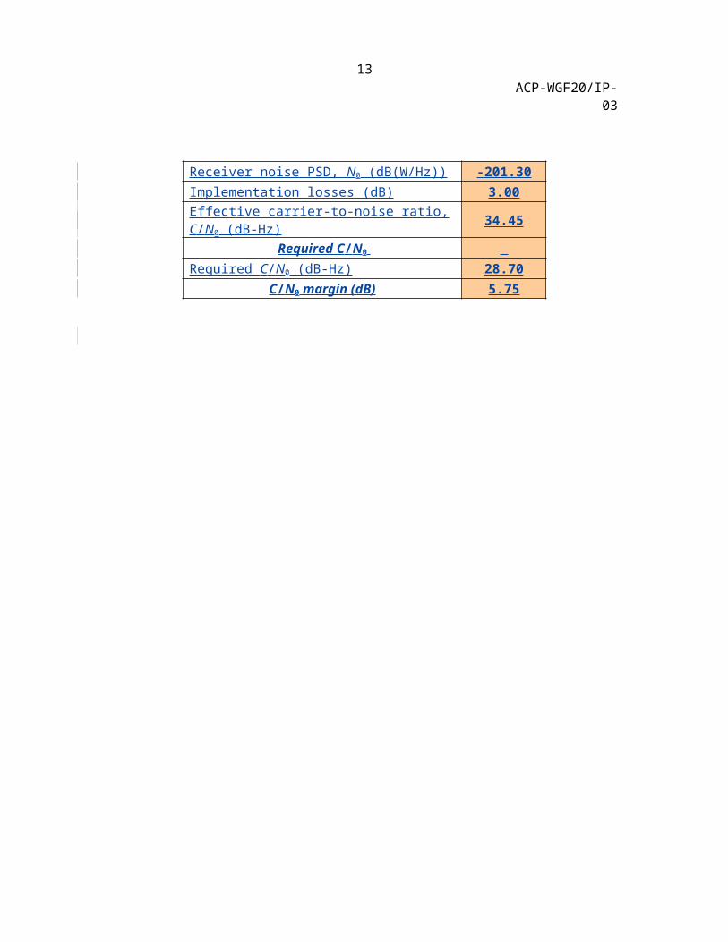
Received power, C (dBW) -163.85Noise PSD –
Receiver system noise temperature, T (K) 530.00Receiver noise PSD, N0 (dB(W/Hz)) -201.30Implementation losses (dB) 3.00Effective carrier-to-noise ratio, C/N0 (dB-Hz) 34.45
Required C/N0 Required C/N0 (dB-Hz) 28.70
C/N0 margin (dB) 5.75
10
ACP-WGF20/IP-0311
ACP-WGF20/IP-03
TABLE 1-3
Galileo service link budgets for tracking for Spot Coverage (typical).
Parameter Value
GNSS SV altitude (km) 23228.00
PolarizationRHCP/
LHCP(both planned)
Space loss Receiver elevation angle (deg) 10.00Maximum slant range to orbit (km) 27824.6Free space path loss (dB) 195.35Propagation losses (dB)(Note: 9dB may be required in tropical regions)
4.5
Other signal losses (dB) 1.00Total space losses (dB) 200.85
Transmitter e.i.r.p.Transmitter antenna gain (dBi) 27Transmitter power (W) 269.15Transmit power (dBW) 24.30E.i.r.p. (dBW) 51.3
Received power Received isotropic power (dBW) -149.55Receiver antenna gain, G (dBi)(Note2: Typical range between 10 and 90 degrees for patch antennas is between -5 to 5 dBi)
-2.00
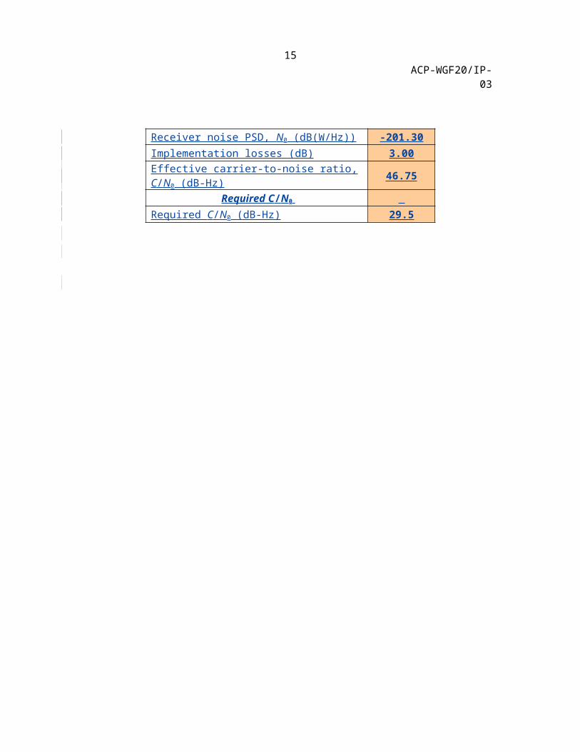
Received power, C (dBW) -151.55Noise PSD –
Receiver system noise temperature, T (K) 530.00Receiver noise PSD, N0 (dB(W/Hz)) -201.30Implementation losses (dB) 3.00Effective carrier-to-noise ratio, C/N0 (dB-Hz) 46.75
Required C/N0 Required C/N0 (dB-Hz) 29.5
12
ACP-WGF20/IP-0313
ACP-WGF20/IP-03
Annex 2
Technical characteristics and protection criteria of receiving earth stations and characteristics of transmitting space stations in the Global Positioning
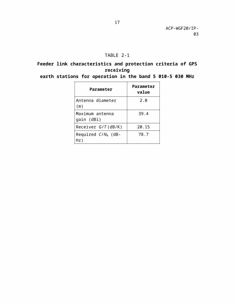
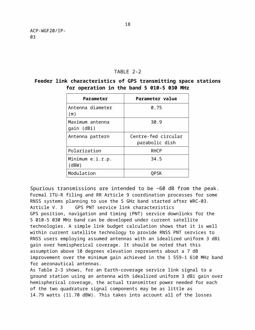
System (GPS) operating (space-to-Earth) in the band 5 010-5 030 MHzArticle III. 1 IntroductionThe Global Positioning System (GPS) uplink and downlink feeder links will provide communications for system and satellite monitoring, commanding and control; updates of orbit ephemerides; and clock synchronization. GPS service links will provide position, navigation and timing (PNT) to properly equipped users. Article IV. 2 GPS feeder downlink characteristicsGPS plans estimate the 3 dB bandwidth of the feeder downlink to be 6 MHz, with a rate of 6 megabits per second. The space station’s feeder downlink antenna is assumed to be a centre-fed circular parabolic dish which is also assumed to be used as the uplink receive antenna for any 5 000-5 010 MHz feeder link uplink transmissions (cf. Recommendation ITU-R M.[E-S Tx+Rx]). However, due to the fact that the 5 000-5 010 MHz Earth-to-space and 5 010-5 030 MHz space-to-Earth bands are adjacent, using both within a given RNSS system could be technically challenging. Possible approaches include the implementation of satellite filters with very sharp cut-offs and time division multiplexing of the signals. However, at this point, studies have not concluded on whether satellites could implement both feeder links and service links at 5 GHz. Further study on both of these topics is necessary as this and other RNSS systems planned for this band mature.Table 2-1 provides characteristics and protection criteria of GPS receiving feeder-link earth stations for operation in the band 5 010-5 030 MHz. Table 2-2 provides characteristics of the corresponding GPS transmitting space station feeder links.
TABLE 2-1
Feeder link characteristics and protection criteria of GPS receivingearth stations for operation in the band 5 010-5 030 MHz
Parameter Parameter value
Antenna diameter (m) 2.0Maximum antenna gain (dBi)
39.4
Receiver G/T (dB/K) 20.15Required C/N0 (dB-Hz) 78.7
14
ACP-WGF20/IP-03
TABLE 2-2
Feeder link characteristics of GPS transmitting space stationsfor operation in the band 5 010-5 030 MHz
Parameter Parameter value
Antenna diameter (m) 0.75Maximum antenna gain (dBi)
30.9
Antenna pattern Centre-fed circular parabolic dish
Polarization RHCPMinimum e.i.r.p. (dBW) 34.5Modulation QPSK
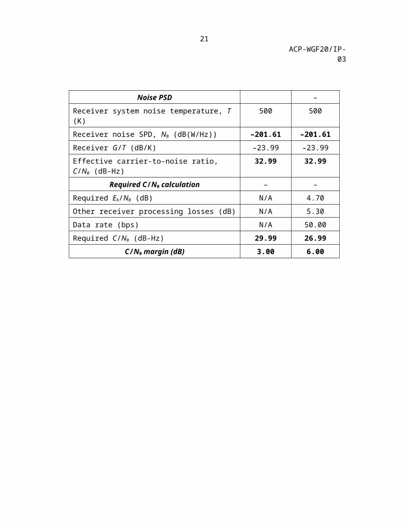
Spurious transmissions are intended to be −60 dB from the peak. Formal ITU-R filing and RR Article 9 coordination processes for some RNSS systems planning to use the 5 GHz band started after WRC-03.Article V. 3 GPS PNT service link characteristicsGPS position, navigation and timing (PNT) service downlinks for the 5 010-5 030 MHz band can be developed under current satellite technologies. A simple link budget calculation shows that it is well within current satellite technology to provide RNSS PNT services to RNSS users employing assumed antennas with an idealized uniform 3 dBi gain over hemispherical coverage. It should be noted that this assumption above 10 degrees elevation represents about a 7 dB improvement over the minimum gain achieved in the 1 559-1 610 MHz band for aeronautical antennas.As Table 2-3 shows, for an Earth-coverage service link signal to a ground station using an antenna with idealized uniform 3 dBi gain over hemispherical coverage, the actual transmitter power needed for each of the two quadrature signal components may be as little as 14.79 watts (11.70 dBW). This takes into account all of the losses indicated in the link budget. Propagation losses are estimated at 5 dB and include components for ionospheric, tropospheric, rain and water vapour losses. “Other signal losses” include 2 dB for polarization mismatch loss and antenna pointing errors. Antenna efficiency losses are accounted for by separate 1 dB entries and are reflected in the gain values for the transmitting and receiving antennas. Receiver processing losses, which apply only to the tracking mode and include data demodulation correlation losses and cable losses, are estimated at 5.3 dB. Table 2-3 below assumes the required C/N0 for acquisition is lower than many current L-band receivers and anticipates improved signal correlator hardware or possible use of a dataless signal – which would, of course, decrease the required satellite transmitter power. Improvement in correlators or use of a phase-lock loop (PLL) to acquire a dataless signal would not affect the tracking threshold, and so the 3 dB difference between required acquisition and tracking levels is appropriately less than the 6 dB difference typical of L-band receivers.A downlink signal modulation, which meets 5 GHz service link requirements is filtered staggered quadrature phase-shift-key with a 10 megabit per second pseudorandom spreading code (SQPSK(10)). The SQPSK signal could have a dataless component, to aid signal acquisition, in quadrature with a data component. The filtering would provide protection for services in other bands, while the filtered
15
ACP-WGF20/IP-03
SQPSK(10) still provides good characteristics for PNT and transmit power
16
ACP-WGF20/IP-03
and signal generation. The signal would be circularly polarized, but whether right- or left-handed is a design choice that could depend on the polarization of other signals in the band; viz., RNSS feeder links.
TABLE 2-3
Example GPS service link budgets for acquisition and tracking
Parameter Acquisition value
Tracking value
Space loss – –
GPS SV altitude (km) 20 200 20 200
Minimum receiver elevation angle (deg) 10 10
Maximum slant range to orbit (km) 24 718 24 718
Free space path loss (dB) 194.32 194.32
Propagation losses (dB) 5.00 5.00
Other signal losses (dB) 2.00 2.00
Total space losses (dB) 201.32 201.32Transmitter e.i.r.p. –
Transmitter antenna gain (dBi) 18.00 18.00
Transmitter power (W) 14.79 14.79
E.i.r.p. (dBW) 29.70 29.70Received power –
Received isotropic power (dBW) –171.62 –171.62
Receiver antenna diameter (m) 0.03 0.03
Receiver antenna efficiency loss (dB) 1.00 1.00
Receiver antenna gain, G (dBi) 3.00 3.00
Received power, C (dBW) –168.62 –168.62Noise PSD –
Receiver system noise temperature, T (K) 500 500
Receiver noise SPD, N0 (dB(W/Hz)) –201.61 –201.61Receiver G/T (dB/K) –23.99 –23.99
Effective carrier-to-noise ratio, C/N0 (dB-Hz) 32.99 32.99Required C/N0 calculation – –
Required Eb/N0 (dB) N/A 4.70
17
ACP-WGF20/IP-03
Other receiver processing losses (dB) N/A 5.30
Data rate (bps) N/A 50.00
Required C/N0 (dB-Hz) 29.99 26.99C/N0 margin (dB) 3.00 6.00
18
ACP-WGF20/IP-03
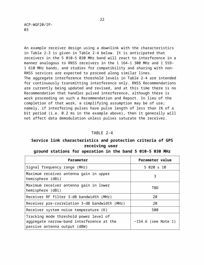
An example receiver design using a downlink with the characteristics in Table 2-3 is given in Table 2-4 below. It is anticipated that receivers in the 5 010-5 030 MHz band will react to interference in a manner analogous to RNSS receivers in the 1 164-1 300 MHz and 1 559-1 610 MHz bands, and studies for compatibility and sharing with non-RNSS services are expected to proceed along similar lines. The aggregate interference threshold levels in Table 2-4 are intended for continuously transmitting interference only. RNSS Recommendations are currently being updated and revised, and at this time there is no Recommendation that handles pulsed interference, although there is work proceeding on such a Recommendation and Report. In lieu of the completion of that work, a simplifying assumption may be of use; namely, if interfering pulses have pulse length of less than 1% of a bit period (i.e. 0.2 ms in the example above), then it generally will not affect data demodulation unless pulses saturate the receiver.
TABLE 2-4
Service link characteristics and protection criteria of GPS receiving user ground stations for operation in the band 5 010-5 030 MHz
Parameter Parameter value
Signal frequency range (MHz) 5 020 ± 10Maximum receiver antenna gain in upper hemisphere (dBi) 3Maximum receiver antenna gain in lower hemisphere (dBi) TBDReceiver RF filter 3-dB bandwidth (MHz) 20Receiver pre-correlation 3-dB bandwidth (MHz) 20Receiver system noise temperature (K) 500Tracking mode threshold power level of aggregate narrow-band interference at the passive antenna output (dBW) −154.6 (see Note 1)
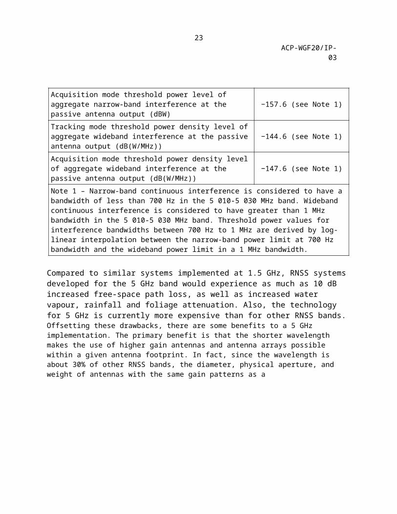
Acquisition mode threshold power level of aggregate narrow-band interference at the passive antenna output (dBW) −157.6 (see Note 1)
Tracking mode threshold power density level of aggregate wideband interference at the passive antenna output (dB(W/MHz)) −144.6 (see Note 1)
Acquisition mode threshold power density level of aggregate wideband interference at the passive antenna output (dB(W/MHz)) −147.6 (see Note 1)
Note 1 – Narrow-band continuous interference is considered to have a bandwidth of less than 700 Hz in the 5 010-5 030 MHz band. Wideband continuous interference is considered to have greater than 1 MHz bandwidth in the 5 010-5 030 MHz band. Threshold power values for interference bandwidths between 700 Hz to 1 MHz are derived by log-linear interpolation between the narrow-band power limit at 700 Hz bandwidth and the wideband power limit in a 1 MHz bandwidth.
Compared to similar systems implemented at 1.5 GHz, RNSS systems developed for the 5 GHz band would experience as much as 10 dB increased free-space path loss, as well as increased water vapour, rainfall and foliage attenuation. Also, the technology for 5 GHz is currently more expensive than for other RNSS bands. Offsetting these drawbacks, there are some benefits to a 5 GHz implementation. The primary benefit is
19

ACP-WGF20/IP-03
that the shorter wavelength makes the use of higher gain antennas and antenna arrays possible within a given antenna footprint. In fact, since the wavelength is about 30% of other RNSS bands, the diameter, physical aperture, and weight of antennas with the same gain patterns as a
20
ACP-WGF20/IP-03
similar antenna in the 1.5 GHz range is reduced by roughly factors of 0.3, (0.3)2 = 0.09, and (0.3)3 = 0.027 respectively. This may lend itself to applications for which size and weight are strong system constraints for both user equipment and satellite payloads. This, in turn, may enable the use of adaptive antennas with the capability to increase received signal power or put nulls on RFI sources or both. Such capabilities are useful since unwanted emissions from other services could interfere with RNSS signals at short range. Such antennas however may not be suitable for all applications. In addition, since such an antenna consists of a number of antenna elements, receiver front-ends and beam-forming/steering electronics, the receiver architecture becomes complex. Another benefit to a 5 GHz implementation is the potential for improved position and timing accuracy. This is due to the reduced variability in ionospheric propagation delay. As noted in Section 2 above, no studies have concluded on how 5 GHz service links would work in the presence of RNSS feeder downlinks. Further study could include such techniques as orthogonal circular polarizations, modulations with low cross-correlation properties, and incorporating more link margin for RFI from feeder downlinks. Also, the compatibility of simultaneous feeder downlink and service link signals from different RNSS systems needs to be considered.Protection criteria for the service link signals need to be further developed as RNSS system designs mature. Those protection criteria should take into account the RNSS features necessary to ensure the receiver can operate in its intended environment, including any signal bandwidth and filtering constraints to ensure compatibility with radio astronomy. In addition, if the RNSS link will be fielded in an airport environment, it should be designed to tolerate unwanted emissions from the ICAO standard microwave landing system (MLS) operating in the adjacent band. Such signals can reach levels up to 63 dBm/150 kHz at frequencies just above 5 030 MHz. More 5 GHz RNSS receiver details will become available after initial system designs are completed.
21
ACP-WGF20/IP-03
Annex 3
Technical characteristics and protection criteria of receiving earth stations and characteristics of transmitting space stations in the Quasi-Zenith Satellite
System (QZSS) operating in the band 5 010-5 030 MHzArticle VI. 1 IntroductionThe QZSS uplink and downlink feeder links will provide communications for system and satellite monitoring, command, control, and navigation message upload. The QZSS control stations are planned to be located in the Asia-Pacific Region.Article VII. 2 QZSS characteristicsCharacteristics and protection criteria of QZSS receiving earth stations operating in the band 5 010-5 030 MHz are provided in Table 3-1. Characteristics of QZSS transmitting space stations operating in the band 5 010-5 030 MHz are provided in Table 3-2.In order to avoid self-interference, a filtering technique will be implemented in QZSS satellites. Furthermore, only the lower portion of the 5 000-5 010 MHz uplink frequency band and the upper portion of the 5 010-5 030 MHz downlink frequency band are used.
TABLE 3-1
Characteristics and protection criteria of QZSS receiving earth stations operating in the band 5 010-5 030 MHz
Parameter Parameter value
Antenna pattern Rec. ITU-R S.465-5Maximum antenna gain (dBi) 45.4Necessary bandwidth (kHz) 400Noise temperature (K) 150Required C/N0 (dB-Hz) 56.5 for telemetry** In case of other uplink applications such as ranging, appropriate
values should be exchanged in bilateral discussions.
TABLE 3-2
Characteristics of QZSS transmitting space stations operating in the band 5 010-5 030 MHz
Parameter Parameter value
Antenna pattern Global beamPolarization RHCP
22
ACP-WGF20/IP-03
Transmit EIRP (dBW) 23.3/9.8Modulation PCM-PSK/PM
23

ACP-WGF20/IP-03
{Editor’s Note: The following paragraph and Table 3-3 are shown as being restored here in Annex 3 (from the deleted Annex 5) so that this material, originally proposed by Japan in Doc 4C/50, is not lost.}RR footnote No. 5.443B states, “In order not to cause harmful interference to the microwave landing system operating above 5 030 MHz, the aggregate power flux-density produced at the Earth’s surface in the band 5 030-5 150 MHz by all the space stations within any radionavigation-satellite service system (space-to-Earth) operating in the band 5 010-5 030 shall not exceed −124.5 dB(W/m2) in a 150 kHz band.” In Table 3-3, the maximum aggregate pfd level that is produced by transmitting space stations of an example RNSS system in the 5 030-5 150 MHz band is calculated. These calculations show that the RNSS transmitting space stations will meet an aggregate pfd level of −124.5 dB(W/m2) in a 150 kHz band with more than 5 dB of margin.
TABLE 3-3
Example RNSS system unwanted emissions in the band 5 030-5 150 MHz
Parameter Value
E.i.r.p. spectral density (dBW/150 kHz) in the band 5 030-5 150 MHz (satellite filter attenuation is taken into account)
26.0
Minimum distance from satellite to the surface of the Earth (km) 31 602Aggregation factor due to number (3) of satellites (dB) 4.8Aggregate pfd (dBW/m2 in 150 kHz) in the band 5 030-5 150 MHz −130.2
24