gaes project potential benefits of fuel cell usage in the ... · gaes project - potential benefits...
TRANSCRIPT
GAES project:Potential Benefits of Fuel Cell Usage in the Aviation Context
EEC/SEE/2006/004

GAES project: Potential Benefits of Fuel Cell Usage in the Aviation Context Prepared for EUROCONTROL Experimental Centre by: GAES Extern project team under ISA Software Contract: Authors: ENVISA: Sandrine Carlier, [email protected] Ayce Celikel, [email protected] Nicolas Duchene, [email protected] QinetiQ: Chris Eyers, [email protected] Gary Mepsted EUROCONTROL Project Manager: Frank Jelinek: [email protected] EEC Note: EEC/SEE/2006/004
© European Organisation for the Safety of Air Navigation EUROCONTROL 2006 This document is published by EUROCONTROL in the interest of the exchange of information. It may be copied in whole or in part providing that the copyright notice and disclaimer are included. The information contained in this document may not be modified without prior written permission from EUROCONTROL. EUROCONTROL makes no warranty, either implied or express, for the information contained in this document, neither does it assume any legal liability or responsibility for the accuracy, completeness or usefulness of this information.

GAES project - Potential Benefits of Fuel Cell Usage in the Aviation Context
EEC/SEE/2006/004 iii
EXECUTIVE SUMMARY
The “Potential Benefits of Fuel Cell Usage in the Aviation Context” study is part of the EUROCONTROL SEE GAES-Extern project and was initiated in order to assess the potential environmental benefits of fuel cell usage in aviation. The initial objective of this report was the evaluation of the impacts of the replacement of gas turbine Auxiliary Power Unit (APU) by fuel cell powered APU. However, due to the large variety of fuel cells available, and its variety of use in the airports, the scope of the project was widened to include also other applications than APU. As a consequence, a thorough literature review has been performed which highlights the potential benefits of fuel cell usage in the aviation context, besides APU. The APU usage is part of the aircraft emissions. Thus, for environmental considerations it is important to improve the efficiency by reducing the fuel burn and emissions. Fuel cells provide a good solution for both economical and environmental improvements; however the technology is still under development for a widespread use. The report consists of literature review of fuel cell technologies, their specific applications in airports, APU fuel cell replacement case study and following results and conclusions. From the literature review of fuel cell types in airports, some representative parameters such as emission factors are found in order to estimate the emissions. Then a case study is developed which focuses on the replacement of traditional APU by fuel cell APU. A European airport where the traditional APU data exist is used as a case study to evaluate the benefits of using fuel cells in terms of fuel consumption and emissions. The case study defines three scenarios likely to occur at the case study airport. Pollutants considered are NOx mainly even though CO and HC have also been estimated. Fuel burnt is also reported with special interest. The use of fuel cell APU is expected to induce a fuel consumption equal to one third of a traditional gas turbine APU, reducing thereby the emissions. Moreover the fuel cell technology is such that no NOx are generated. Another finding was the need to develop further the fuel cell technology so that its performances reach an acceptable level. At the moment, there are a number of issues such as the weight and the volume of fuel cells, as well as their relatively short lifetime and their expensiveness which need to be solved. However, the environmental benefits of fuel cells are likely to increase among the aviation actors especially if aviation is to be included in an EU emissions trading scheme.

GAES project - Potential Benefits of Fuel Cell Usage in the Aviation Context
iv EEC/SEE/2006/004
(This page intentionally blank)
GAES project - Potential Benefits of Fuel Cell Usage in the Aviation Context
EEC/SEE/2006/004
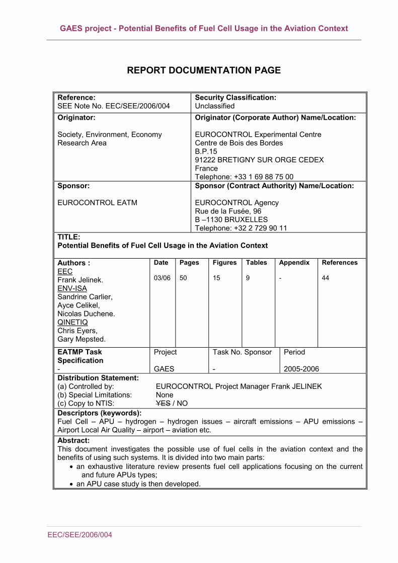
REPORT DOCUMENTATION PAGE
Reference: SEE Note No. EEC/SEE/2006/004
Security Classification: Unclassified
Originator: Society, Environment, Economy Research Area
Originator (Corporate Author) Name/Location: EUROCONTROL Experimental Centre Centre de Bois des Bordes B.P.15 91222 BRETIGNY SUR ORGE CEDEX France Telephone: +33 1 69 88 75 00
Sponsor: EUROCONTROL EATM
Sponsor (Contract Authority) Name/Location: EUROCONTROL Agency Rue de la Fusée, 96 B –1130 BRUXELLES Telephone: +32 2 729 90 11
TITLE: Potential Benefits of Fuel Cell Usage in the Aviation Context Authors : EEC Frank Jelinek. ENV-ISA Sandrine Carlier, Ayce Celikel, Nicolas Duchene. QINETIQ Chris Eyers, Gary Mepsted.
Date 03/06
Pages 50
Figures 15
Tables 9
Appendix -
References 44
EATMP Task Specification -
Project GAES
Task No. Sponsor -
Period 2005-2006
Distribution Statement: (a) Controlled by: EUROCONTROL Project Manager Frank JELINEK (b) Special Limitations: None (c) Copy to NTIS: YES / NO Descriptors (keywords): Fuel Cell – APU – hydrogen – hydrogen issues – aircraft emissions – APU emissions – Airport Local Air Quality – airport – aviation etc. Abstract: This document investigates the possible use of fuel cells in the aviation context and the benefits of using such systems. It is divided into two main parts:
• an exhaustive literature review presents fuel cell applications focusing on the current and future APUs types;
• an APU case study is then developed.

GAES project - Potential Benefits of Fuel Cell Usage in the Aviation Context
vi EEC/SEE/2006/004
(This page intentionally blank)

GAES project - Potential Benefits of Fuel Cell Usage in the Aviation Context
EEC/SEE/2006/004
TABLE OF CONTENTS
Table of Contents...................................................................................................... 7
List Of Tables ............................................................................................................ 8
List of Figures ........................................................................................................... 8
ABBREVIATIONS ...................................................................................................... 9
1 INTRODUCTION .................................................................................................. 1 1.1 History ...................................................................................................................................... 1
1.1.1 Issue and Scope ............................................................................................................... 1
1.1.2 Fuel Cell Technology ........................................................................................................ 2
1.1.3 Advantages of Fuel cell .................................................................................................... 2
1.1.4 Fuel Cell Implementation Considerations......................................................................... 3
1.2 Fuel Cell Application to Airport Activities.................................................................................. 4 1.3 Project Approach ...................................................................................................................... 5
2 LITTERATURE REVIEW...................................................................................... 6 2.1 APU, GPU and Fixed Electric Ground Power (FEGP) ............................................................. 6 2.2 APU Emissions......................................................................................................................... 7 2.3 Fuel Cells.................................................................................................................................. 9 2.4 Fuel Cells Applications in the Airport Context ........................................................................ 12
2.4.1 Auxiliary Power Unit........................................................................................................ 12
2.4.2 Airport Power Plants ....................................................................................................... 13
2.4.3 Airport Special Vehicles & Airside Road Vehicles .......................................................... 16
2.5 Hydrogen Economy................................................................................................................ 20
3 CASE STUDY..................................................................................................... 23 3.1 Method.................................................................................................................................... 23 3.2 Emission amount = APU operating time x emission factor .................................................... 23
3.2.1 Emission factors ............................................................................................................. 23
3.2.2 Statistical reliability ......................................................................................................... 25
3.2.3 Scenarios Definition........................................................................................................ 25
3.3 Summary of the Case Study .................................................................................................. 27 3.4 Results.................................................................................................................................... 28
3.4.1 Evolution of emission over one year – GT APU ............................................................. 28
3.4.2 Top 5 aircraft types – GT and FC APU........................................................................... 29
3.4.3 Comparison of the environmental impact of GT APU and FC APU ............................... 30

GAES project - Potential Benefits of Fuel Cell Usage in the Aviation Context
viii EEC/SEE/2006/004
4 CONCLUSION....................................................................................................32
5 REFERENCES ...................................................................................................33
LIST OF TABLES
FIGURE 1 : BASIC SCHEMATIC OF FUEL CELL...................................................................................................3 FIGURE 2: CO2 EMISSIONS AND EFFICIENCY FOR TRADITIONAL ICE AND METHANOL OR
HYDROGEN FED FUEL CELLS [REF 15.].........................................................................................4 FIGURE 3: FIXED GROUND POWER SUPPLY AT ZURICH AIRPORT [REF 10.]. .............................................6 FIGURE 4: AIR CLIMATE UNIT AT ZURICH AIRPORT [REF 12.].......................................................................7 FIGURE 5: GROUND POWER UNIT AT ZURICH AIRPORT [REF 10.] ................................................................7 FIGURE 6: EXAMPLE OF A 10 KW COMMERCIALISED FUEL CELL FORKLIFT IN USE AT MUNICH
AIRPORT (PICTURE FROM GENERAL HYDROGEN - [REF 24.]). ..............................................17 FIGURE 7: EXAMPLE OF THE TOYOTA HYBRID FUEL CELL BUS (90 KW FUEL CELL STACKS) FROM
[REF 25.]. .............................................................................................................................................18 FIGURE 8: MUNICH AIRPORT HYDROGEN PROJECT OVERVIEW FROM [REF 29.]. ..................................20 FIGURE 9: LAX AIRPORT HYDROGEN PROJECT - FUELLING STATION DESIGN VIEW FROM [REF 30.].
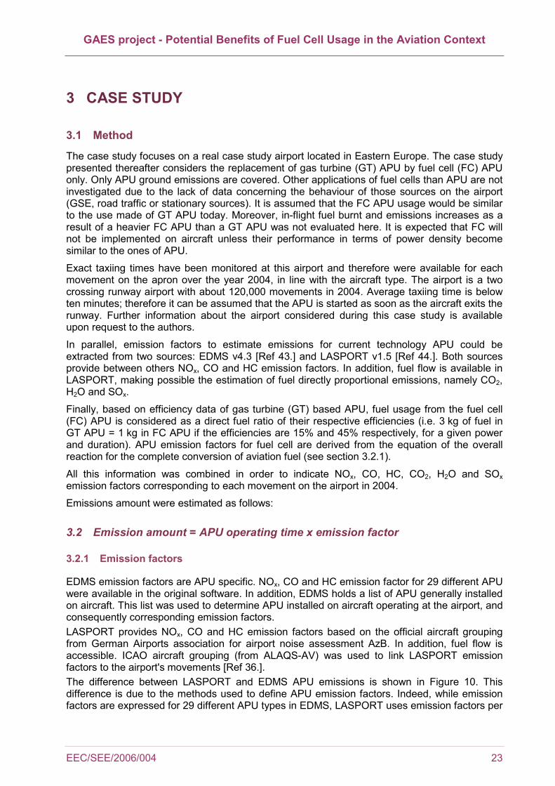
..............................................................................................................................................................20 FIGURE 10: COMPARISON OF "SCENARIO 1" EMISSIONS IN 2004. ...............................................................24 FIGURE 11: LAYOUT OF THE AIRPORT CONSIDERED FROM [REF 37.]. ......................................................27 FIGURE 12: NOX EMISSIONS IN 2004 AT THE CASE STUDY AIRPORT ........................................................28 FIGURE 13: FUEL BURNT IN 2004 AT THE CASE STUDY AIRPORT...............................................................29 FIGURE 14: FUEL BURNT AND POLLUTANTS EMITTED FOR THE 5 MOSTLY USED AIRCRAFT IN 2004
(SCENARIO 2). ....................................................................................................................................30 FIGURE 15: APU EMISSIONS IN 2004 ACCORDING TO VARIOUS SCENARIOS (AVERAGES OF THE
TWO TOOLS). .....................................................................................................................................31
LIST OF FIGURES
TABLE 1-1: EC NON ROAD MOBILE MACHINERY (EEC EUNRMM STAGE 1)...............................................5 TABLE 2-1: APU AND GPU AVERAGED EMISSION FACTORS IN LOCAL AIR QUALITY MODELS...........7 TABLE 2-2: APU EMISSION FACTORS (FROM EDMS V4.3) ...............................................................................8 TABLE 2-3: APU EMISSION FACTORS PER AIRCRAFT GROUP (FROM LASPORT V1.5) .............................8 TABLE 2-4: APU OPERATIONAL PARAMETERS FROM THIRTEEN APU TYPES (MANUFACTURER
DATA) ....................................................................................................................................................8 TABLE 2-5: SUMMARY OF FUEL CELL PARAMETERS AND APPLICATIONS [REF 1.] & [REF 2.] & [REF
15.] ........................................................................................................................................................11 TABLE 2-6: SUMMARY OF FUEL CELL AND OTHER POWER PLANTS PARAMETERS FROM [REF 1.] &
[REF 2.] & [REF 15.] ...........................................................................................................................15 TABLE 2-7: HYDROGEN PRODUCTION COSTS IN US DOLLARS OF 1990 FROM [REF 32.].......................21 TABLE 3-1: YEARLY NUMBER OF MOVEMENT PER GATE AT A SPECIFIC AIRPORT IN 2004................26
GAES project - Potential Benefits of Fuel Cell Usage in the Aviation Context
EEC/SEE/2006/004
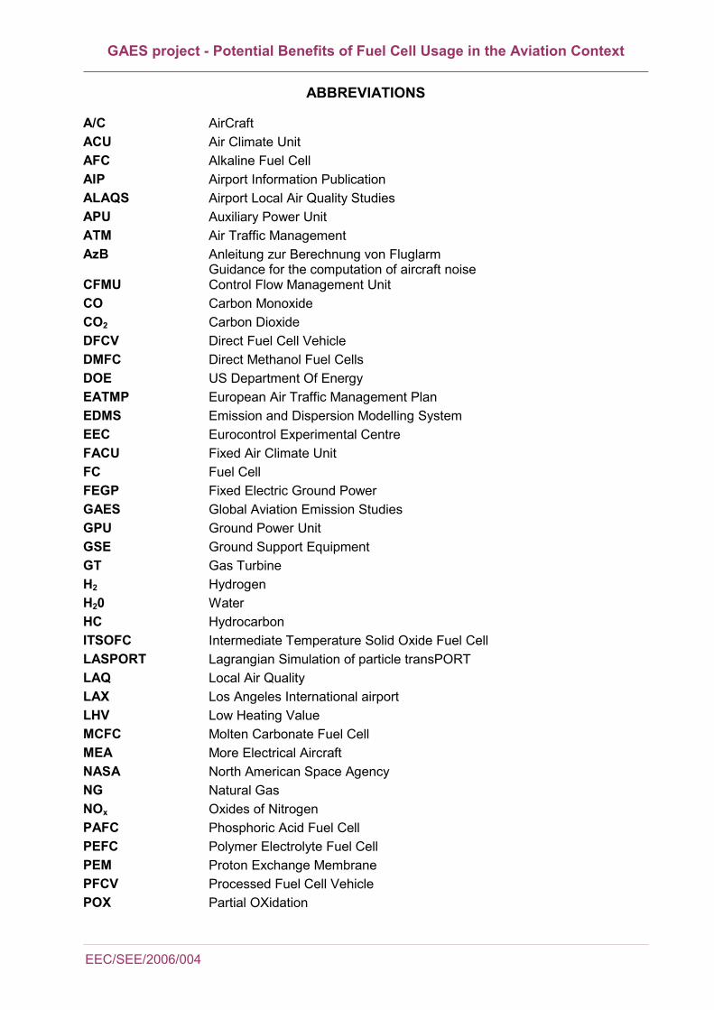
ABBREVIATIONS
A/C AirCraft ACU Air Climate Unit AFC Alkaline Fuel Cell AIP Airport Information Publication ALAQS Airport Local Air Quality Studies APU Auxiliary Power Unit ATM Air Traffic Management AzB Anleitung zur Berechnung von Fluglarm
Guidance for the computation of aircraft noise CFMU Control Flow Management Unit CO Carbon Monoxide CO2 Carbon Dioxide DFCV Direct Fuel Cell Vehicle DMFC Direct Methanol Fuel Cells DOE US Department Of Energy EATMP European Air Traffic Management Plan EDMS Emission and Dispersion Modelling System EEC Eurocontrol Experimental Centre FACU Fixed Air Climate Unit FC Fuel Cell FEGP Fixed Electric Ground Power GAES Global Aviation Emission Studies GPU Ground Power Unit GSE Ground Support Equipment GT Gas Turbine H2 Hydrogen H20 Water HC Hydrocarbon ITSOFC Intermediate Temperature Solid Oxide Fuel Cell LASPORT Lagrangian Simulation of particle transPORT LAQ Local Air Quality LAX Los Angeles International airport LHV Low Heating Value MCFC Molten Carbonate Fuel Cell MEA More Electrical Aircraft NASA North American Space Agency NG Natural Gas NOx Oxides of Nitrogen PAFC Phosphoric Acid Fuel Cell PEFC Polymer Electrolyte Fuel Cell PEM Proton Exchange Membrane PFCV Processed Fuel Cell Vehicle POX Partial OXidation

GAES project - Potential Benefits of Fuel Cell Usage in the Aviation Context
x EEC/SEE/2006/004
SEE Society, Economic, Environment SOFC Solid Oxide Fuel Cell SOx Oxides of Sulphur SR Steam Reformation TSOFC Tubular Solid Oxide Fuel Cell ZnO Zinc Oxide
GAES project - Potential Benefits of Fuel Cell Usage in the Aviation Context
EEC/SEE/2006/004
1 INTRODUCTION
1.1 History
Global Aviation Emission Studies (GAES) is a roof project including all activities and projects managed in the past separately in the area of Global Emission Studies for the Business Area SEE EUROCONTROL. The aim is that systematic emission studies shall test the potential environmental impact or benefit of the different programme elements of the European Air Traffic Management Plan (EATMP) and Air Traffic management (ATM) 2000+ aiming to estimate the complete environmental potential of those programmes. In addition, emission analysis shall become a systematic element to the validation of any EUROCONTROL/EEC ATM/ATM concept or research project. During the last decade, very significant structural changes have been observed in the field of electricity production and distribution. This evolution seems to be just beginning and new and more profound modifications can be expected. These changes in energy policy are mainly due to two different factors: the de-regulation of the electricity market and the Kyoto commitments. Between others, the Fuel Cell (FC) technology receives more and more attentions. That is because it has a low environmental impact, a high electric conversion efficiency, and it produces heat usable for co-generation cycles, integration with gas turbine and fuel flexibility. Despite their high potential, fuel cells are not commonly used for full commercial application due to cost limitation and limited durability. There are some research projects investigating the potential use and improvements of this technology. In air transport industry, Boeing has initiated feasibility study to investigate Solid Oxide Fuel Cell (SOFC) auxiliary power unit (APU) on B737. The combustible for the fuel cell is obtained from hydrocarbons (typically jet fuel) using a reformer. With this technology APU is 45% efficient in turning fuel into electricity in contrast to a gas turbine which is 15% efficient. However as the studies are initiation phase, it is found that fuel cells are not economic on current costs. Yet, by 2010, the technology should have reached a maturity level at which the Auxiliary Power Unit (APU) could be offered on future versions of the Boeing 787. Today a large SOFC require hours to reach operating temperature so the technology is far from commercial. Part of the GAES-Extern project, this study investigates the impact of replacing the conventional APUs and airport equipments with the new fuel technology ones.
1.1.1 Issue and Scope
APU is an auxiliary power unit mainly used to supply power when the main aircraft engines are down. It is an internal engine on aircraft that provides pneumatic air for engine start, aircraft, hydraulics, and power while the engines are off. It is really a smaller version of the main turbine engines that turn alternating current electric generators instead of a fan or propeller. APUs are mainly located in the tail cone of an aircraft and operate on jet fuel. APU engines burn jet fuel and create exhaust emissions like larger engines. APUs contribute 5-10% of the overall aircraft pollution at airports. As airports recently started to include airport emissions in air quality plans to meet the standards, it is important to reduce the emissions with new technologies, especially when considering high air traffic growth in the future. Moreover, Air Traffic Flow Management is provided within Europe by the Central Flow Management Unit (CFMU) which is operated by EUROCONTROL. Part of the CFMU objective is to propagate the delay on ground. (Without CFMU intervention aircraft would have to counter airborne delays during which fuel is burnt and emissions are produced.) During hold-on ground delays, extended use of aircraft engines in idle or Auxiliary Power Unit (APU) might impact on Local Air Quality (LAQ) at the airport. To a lesser extent, the same is true when ground support
GAES project - Potential Benefits of Fuel Cell Usage in the Aviation Context
2 EEC/SEE/2006/004
equipments (GSE) are used instead of APU. Therefore usage of APU/GSE and the type of APU/GSE is important for the emissions. In the future, when more efficient and environmentally friendly APU and GSE will be used, the trade-off will be possible between the en-route delays and the APU/GSE use on ground. Initially, this report focused on the replacement of turbine APU by fuel cells APU. However, it quickly appeared that the use of fuel cell would raise greater benefits in other applications than APU. As a consequence the study was re-oriented to consider the use of fuel cells in the aviation context rather than focusing on APU only. Thus the literature review also includes applications such as fixed and mobile ground support equipment (GSE) and large scale applications (fuel cell used as a generator to provide power = back up power plant). Of course, APU developments are also mentioned.
1.1.2 Fuel Cell Technology
The study will evaluate the possible use of fuel cells in airport/aviation applications and the benefits of using such systems.
1.1.3 Advantages of Fuel cell
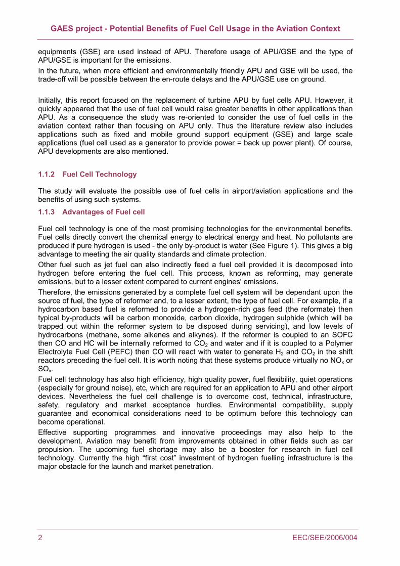
Fuel cell technology is one of the most promising technologies for the environmental benefits. Fuel cells directly convert the chemical energy to electrical energy and heat. No pollutants are produced if pure hydrogen is used - the only by-product is water (See Figure 1). This gives a big advantage to meeting the air quality standards and climate protection. Other fuel such as jet fuel can also indirectly feed a fuel cell provided it is decomposed into hydrogen before entering the fuel cell. This process, known as reforming, may generate emissions, but to a lesser extent compared to current engines' emissions. Therefore, the emissions generated by a complete fuel cell system will be dependant upon the source of fuel, the type of reformer and, to a lesser extent, the type of fuel cell. For example, if a hydrocarbon based fuel is reformed to provide a hydrogen-rich gas feed (the reformate) then typical by-products will be carbon monoxide, carbon dioxide, hydrogen sulphide (which will be trapped out within the reformer system to be disposed during servicing), and low levels of hydrocarbons (methane, some alkenes and alkynes). If the reformer is coupled to an SOFC then CO and HC will be internally reformed to CO2 and water and if it is coupled to a Polymer Electrolyte Fuel Cell (PEFC) then CO will react with water to generate H2 and CO2 in the shift reactors preceding the fuel cell. It is worth noting that these systems produce virtually no NOx or SOx. Fuel cell technology has also high efficiency, high quality power, fuel flexibility, quiet operations (especially for ground noise), etc, which are required for an application to APU and other airport devices. Nevertheless the fuel cell challenge is to overcome cost, technical, infrastructure, safety, regulatory and market acceptance hurdles. Environmental compatibility, supply guarantee and economical considerations need to be optimum before this technology can become operational. Effective supporting programmes and innovative proceedings may also help to the development. Aviation may benefit from improvements obtained in other fields such as car propulsion. The upcoming fuel shortage may also be a booster for research in fuel cell technology. Currently the high “first cost” investment of hydrogen fuelling infrastructure is the major obstacle for the launch and market penetration.
GAES project - Potential Benefits of Fuel Cell Usage in the Aviation Context
EEC/SEE/2006/004
1.1.4 Fuel Cell Implementation Considerations
Fuel Cell Definition: A fuel cell is an electrochemical device that combines fuel and an oxidant to produce electricity. The fuel is typically hydrogen and oxygen the oxidant, with water and heat as the by-product. A fuel cell is similar in structure to a battery but it does not run down, nor does it require recharging – as long as fuel is supplied, it will continue to operate. The conversion of the fuel (hydrogen) to energy takes place without combustion; therefore the process is highly efficient, clean and quiet.
Figure 1 : Basic schematic of fuel cell
Fuel cells have a wide number of applications in various fields such as energy and transportation. For example they can be used as stationary or mobile electric generators and also replace conventional automotive engines. From the US Department Of Energy (DOE) fuel cell handbook [Ref 1.] the most common classification of fuel cells is by type of electrolyte. There are six categories defined as follow:
• Polymer Electrolyte Fuel Cell (PEFC) (also called Proton Exchange Membrane PEM) (user-friendly technology, used in transportation demonstrations and small power applications)
• Alkaline Fuel Cell (AFC) (This has been used in space applications since 1960’s)
• Phosphoric Acid Fuel Cell (PAFC) (Most commercially developed type, mostly used in hospitals, schools, and airports)
• Molten Carbonate Fuel Cell (MCFC) (In demonstration phase for baseload power)
• Direct methanol fuel cells (DMFC) (New member of the fuel cell family, directly oxidises liquid methanol, eliminating the need for a fuel reformer) [Ref 2.]

GAES project - Potential Benefits of Fuel Cell Usage in the Aviation Context
4 EEC/SEE/2006/004
• Intermediate Temperature Solid Oxide Fuel Cell (ITSOFC)
• Tubular Solid Oxide Fuel Cell (TSOFC)
Each category of fuel cell has its specific operating temperature and useful life time dictated by the mechanism of the cell as well as the physicochemical properties of its components. Fuel cells present a wide range of operating conditions and subsequently each category has specific advantages and disadvantages. They will be developed in section 2.3. The most suitable fuel cell category depends on the application needs. For example, PEMFC is mostly used to provide vehicle motive power. However, fuel cells are likely to be more efficient than conventional engines whilst generating less emissions and noise [Ref 3.].
Figure 2: CO2 emissions and efficiency for traditional ICE and methanol or hydrogen fed fuel cells [Ref 15.].
1.2 Fuel Cell Application to Airport Activities
The large range of operating conditions that can be reached by fuel cells makes the fields of application numerous. Focusing on the aviation domain, and more specifically airports and aircraft1, all the airport activities that could be powered by fuel cells will be considered in this document, at least on review level. Benefits of using such system will be highlighted. The following list of airport activities is not exhaustive:
• Aircraft Auxiliary Power Unit (APU)
• Power / heating plants (primary and emergency)
• Airside road equipment (personal cars, van and pick-ups, shuttle buses, trucks and tractors)
• Ground Power Unit (GPU)
• Gate handling equipments (conveyors, fuel trucks, catering and water trucks…)
For each airport activity, the most suitable fuel cell will be defined in section 2.4.
1 Fuel cell powered aircraft are not included in the context of the study. Focus is put on fuel cell APUs.

GAES project - Potential Benefits of Fuel Cell Usage in the Aviation Context
EEC/SEE/2006/004
APUs are used on a routine basis throughout much of the time when an aircraft is on the ground. Operating practices are largely determined by individual airlines and vary considerably among aircraft types and airlines. APU emissions of significance are hydrocarbon (HC), carbon monoxide (CO), oxides of nitrogen (NOx), and sulphur dioxide (SO2). Their replacement by fuel cells is expected to reduce aircraft fuel consumption, emissions and noise. Moreover fuel cell APUs are likely to be more efficient as explained in [Ref 3.] and [Ref 4.]. In the context of airport local air quality (i.e. below 3000 ft) APU emissions represent between 3% and 10% of total aircraft emissions for CO and NOx as reported in [Ref 5.] to [Ref 8.]. It is expected that the use of a fuel cell will eliminate these emissions figures. Table 1-1: EC Non Road Mobile Machinery (EEC EUNRMM Stage 1)
1.3 Project Approach
The study structure plan was defined with the collaboration of two teams (ENV-ISA and QinetiQ) and reviewed by EEC Manager. The approach is: Study Scope Definition: The study evaluates the possible use of fuel cells in airport/aviation applications and the benefits of using such systems. In particular the case study is limited to the replacement of APU by fuel cells. Literature Review: Literature is reviewed to better understand fuel cell technology its benefits and limitations. This is followed by some examples found in airport/aviation applications. From that analysis, the most used applications are listed. Case Study: The study evaluates two scenarios, one with possible use of fuel cells partially in the airport/aircraft operations and the other; baseline scenario with the current technology. An European airport example is used to extract fleet and airport operations. From that example some estimation can be done to calculate possible benefits of changing the current technology with the fuel cell ones.
GAES project - Potential Benefits of Fuel Cell Usage in the Aviation Context
6 EEC/SEE/2006/004
2 LITTERATURE REVIEW
2.1 APU, GPU and Fixed Electric Ground Power (FEGP)
An APU is a small turbine engine carried by large aircraft, both commercial and military. It provides electricity and, indirectly compressed air to operate the aircraft instruments when the main engines are shut down. The APU can act as back up internal power during flight and as primary power when the aircraft is on the ground to provide cabin air conditioning and, for example, lighting. The APU is also used for at least one main engine start-up. It burns jet fuel, and therefore produces noise and emissions in a similar manner to the aircraft's main engines.
According to the FAA Air Quality Procedure for Airports [Ref 11.], "the APU is turned on as the aircraft taxis from the runway to the gate or parking space. It remains in use while the aircraft is parked, unless an alternative source of electricity and preconditioned air is made available. In such case, the APU is reactivated at least five to ten minutes before the aircraft leaves the gate or parking space in order to provide power for starting the aircraft's main engine. Typically, the APU is turned off after the main engines have been started, prior to take off".
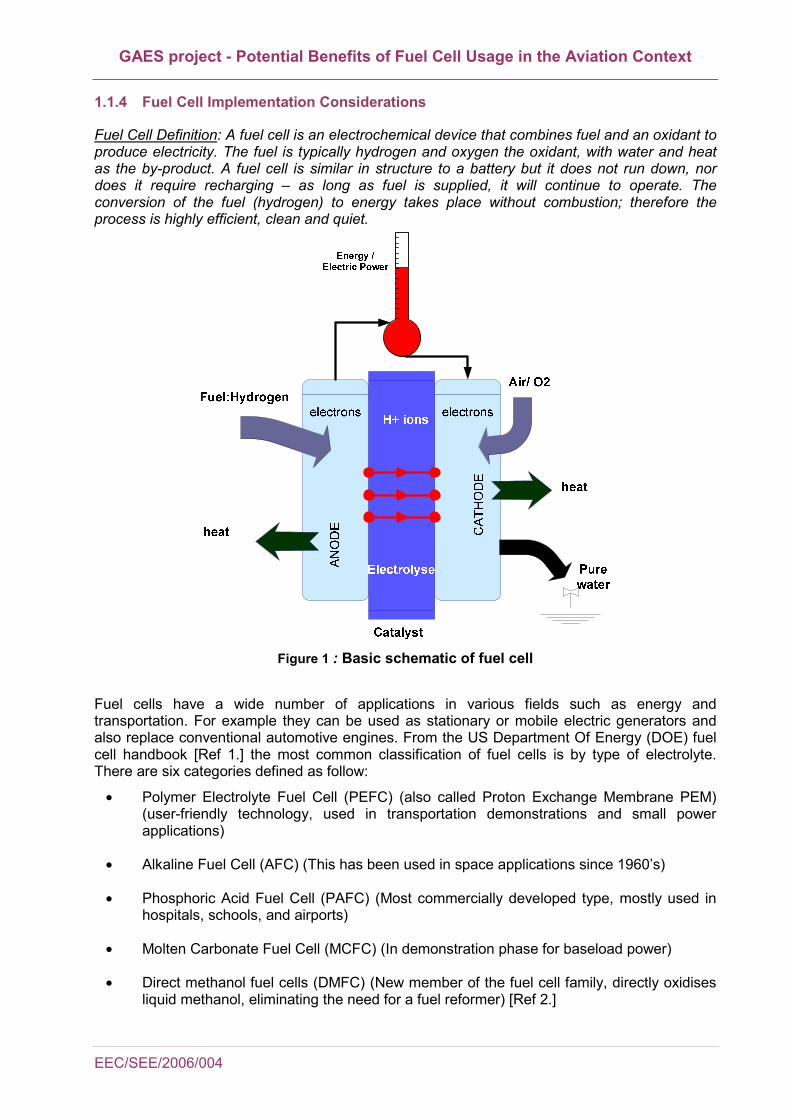
There are two possible sources of electricity and compressed air other than the APU depending on whether the aircraft is parked on a pier or a remote stand. Aircraft parked at a pier stand can obtain electrical power and compressed air using a ground power system providing that the airport has invested in such equipment. Such a power system is called Fixed Electric Ground Power (FEGP) and is shown in Figure 3.
Figure 3: Fixed ground power supply at Zurich airport [Ref 10.].
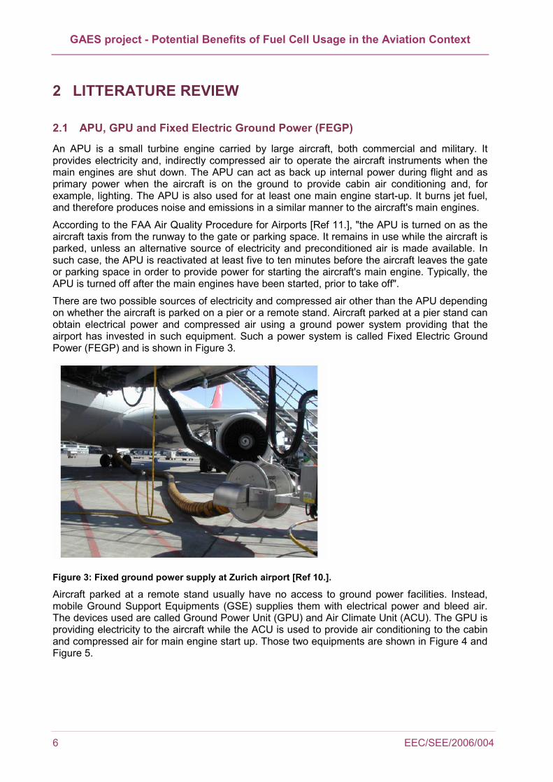
Aircraft parked at a remote stand usually have no access to ground power facilities. Instead, mobile Ground Support Equipments (GSE) supplies them with electrical power and bleed air. The devices used are called Ground Power Unit (GPU) and Air Climate Unit (ACU). The GPU is providing electricity to the aircraft while the ACU is used to provide air conditioning to the cabin and compressed air for main engine start up. Those two equipments are shown in Figure 4 and Figure 5.
GAES project - Potential Benefits of Fuel Cell Usage in the Aviation Context
EEC/SEE/2006/004
Figure 4: Air Climate Unit at Zurich Airport [Ref 12.].
Figure 5: Ground Power Unit at Zurich Airport [Ref 10.]
The FAA procedure is in accordance with the regulation of APUs at Zurich airport [Ref 10.]:
"Primarily, the stationary airport pneumatic and electric service units shall be used. Alternatively, mobile units shall be used.
APU shall only be started:
To start engine, but earliest 5 minutes before off-block time.
If maintenance work on the aircraft makes it unavoidable; in that case the service period shall be kept as short as possible.
If the stationary or mobile units are not available or unserviceable for specific aircraft types. In that case APU shall be started at earliest 60 minutes before off-block time and kept in operation no more than 20 minutes after the on-block time."
Note that APU operations are mainly subject to airlines strategic choices, and at the end of the day the time of APU usage depends on them even though they have to comply with some regulations at certain airports.
2.2 APU Emissions
As reported in [Ref 5.] to [Ref 8.], APU emissions represent between 3% and 10% of total aircraft emissions in terms of local air quality which is not negligible. Data concerning APU emission factors can be obtained either from airport emissions models (such as EDMS or LASPORT2) or from on-site monitored values. For comparison purposes, mobile GPU emission factors are also investigated. Results are shown in Table 2-1: Table 2-1: APU and GPU averaged emission factors in Local Air Quality Models
Pollutant EDMS APU kg/hr
LASPORT APU kg/hr
APU-manufacturer data (averages) kg/hr
GPU kg/hr
CO 1.32 1.46 1.35 0.37 HC 0.08 0.09 0.09 0.10 NOx 0.92 1.31 0.93 0.67
2 EDMS and LASPORT are local air quality modelling tools which are used to estimate airport local air quality. Aircraft and APU emissions are calculated as well as other sources on the airport. More information about those models is available in [Ref 43.] and [Ref 44.]
GAES project - Potential Benefits of Fuel Cell Usage in the Aviation Context
8 EEC/SEE/2006/004
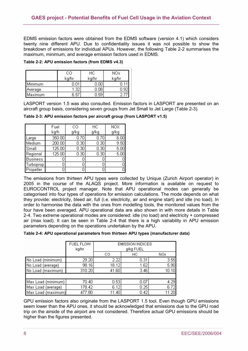
EDMS emission factors were obtained from the EDMS software (version 4.1) which considers twenty nine different APU. Due to confidentiality issues it was not possible to show the breakdown of emissions for individual APUs. However, the following Table 2-2 summarises the maximum, minimum, and average emission factors used in EDMS. Table 2-2: APU emission factors (from EDMS v4.3)
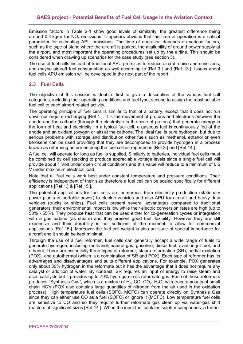
LASPORT version 1.5 was also consulted. Emission factors in LASPORT are presented on an aircraft group basis, considering seven groups from Jet Small to Jet Large (Table 2-3). Table 2-3: APU emission factors per aircraft group (from LASPORT v1.5)
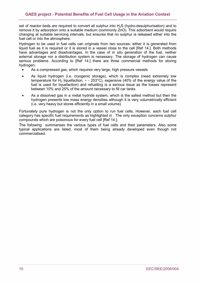
The emissions from thirteen APU types were collected by Unique (Zurich Airport operator) in 2005 in the course of the ALAQS project. More information is available on request to EUROCONTROL project manager. Note that APU operational modes can generally be categorised into four types of operations for emission calculations. The mode depends on what they provide: electricity, bleed air, full (i.e. electricity, air and engine start) and idle (no load). In order to harmonise the data with the ones from modelling tools, the monitored values from the four have been averaged. APU operational data are also shown in with more details in Table 2-4. Two extreme operational modes are considered: idle (no load) and electricity + compressed air (max load). It can be seen in Table 2-4 that there is a high variability in APU emission parameters depending on the operations undertaken by the APU. Table 2-4: APU operational parameters from thirteen APU types (manufacturer data)
GPU emission factors also originate from the LASPORT 1.5 tool. Even though GPU emissions seem lower than the APU ones, it should be acknowledged that emissions due to the GPU road trip on the airside of the airport are not considered. Therefore actual GPU emissions should be higher than the figures presented.
GAES project - Potential Benefits of Fuel Cell Usage in the Aviation Context
EEC/SEE/2006/004
Emission factors in Table 2-1 show good levels of similarity, the greatest difference being around 0.4 kg/hr for NOx emissions. It appears obvious that the time of operation is a critical parameter for estimating APU emissions. The time of operation depends on various factors, such as the type of stand where the aircraft is parked, the availability of ground power supply at the airport, and most important the operating procedures set up by the airline. This should be considered when drawing up scenarios for the case study (see section 3). The use of fuel cells instead of traditional APU promises to reduce aircraft noise and emissions, and maybe aircraft fuel consumption as well according to [Ref 3.] and [Ref 13.]. Issues about fuel cells APU emission will be developed in the next part of the report.
2.3 Fuel Cells
The objective of this session is double: first to give a description of the various fuel cell categories, including their operating conditions and fuel type; second to assign the most suitable fuel cell to each airport related activity. The operating principle of fuel cells is similar to that of a battery, except that it does not run down nor require recharging [Ref 1.]. It is the movement of protons and electrons between the anode and the cathode (through the electrolyte in the case of protons) that generate energy in the form of heat and electricity. In a typical fuel cell, a gaseous fuel is continuously fed at the anode and an oxidant (oxygen or air) at the cathode. The ideal fuel is pure hydrogen, but due to serious problems with storage and distribution other fuels such as methanol, ethanol or even kerosene can be used providing that they are decomposed to provide hydrogen in a process known as reforming before entering the fuel cell as reported in [Ref 3.] and [Ref 14.]. A fuel cell will operate for long as fuel is supplied. Similarly to batteries, individual fuel cells must be combined by cell stacking to produce appreciable voltage levels since a single fuel cell will provide about 1 Volt under open circuit conditions and this value will reduce to a minimum of 0.5 V under maximum electrical load. Note that all fuel cells work best under constant temperature and pressure conditions. Their efficiency is independent of their size therefore a fuel cell can be scaled specifically for different applications [Ref 1.] & [Ref 15.]. The potential applications for fuel cells are numerous, from electricity production (stationary power plants or portable power) to electric vehicles and also APU for aircraft and heavy duty vehicles (trucks or ships). Fuel cells present several advantages compared to traditional generators; their environmental impact is low while their electric conversion rates are high (up to 50% - 55%). They produce heat that can be used either for co-generation cycles or integration with a gas turbine (as steam) and they present good fuel flexibility. However they are still expensive and their durability is not sufficient at the moment to allow for commercial applications [Ref 15.]. Moreover the fuel cell weight is also an issue of special importance for aircraft and it should be kept minimal. Through the use of a fuel reformer, fuel cells can generally accept a wide range of fuels to generate hydrogen, including methanol, natural gas, gasoline, diesel fuel, aviation jet fuel, and ethanol. There are essentially three types of reformer; steam reformation (SR), partial oxidation (POX), and autothermal (which is a combination of SR and POX). Each type of reformer has its advantages and disadvantages and suits different applications. For example, POX generates only about 30% hydrogen in the reformate but it has the advantage that it does not require any catalyst or addition of water. By contrast, SR requires an input of energy to raise steam and uses catalysts but it provides up to 70% hydrogen in its reformate gas. Each of these reformers produces “Synthesis Gas”, which is a mixture of H2, CO, CO2, H2O, with trace amounts of small chain HC’s (POX also contains large quantities of nitrogen from the air used in the oxidation process). High temperature fuel cells (SOFC, MCFC) can operate directly on Synthesis Gas since they can either use CO as a fuel (SOFC) or ignore it (MCFC). Low temperature fuel cells are sensitive to CO and so they require further reformate gas clean up via water-gas shift reactors of significant sizes [Ref 14.]. When the input fuel contains sulphur compounds, a further
GAES project - Potential Benefits of Fuel Cell Usage in the Aviation Context
10 EEC/SEE/2006/004
set of reactor beds are required to convert all sulphur into H2S (hydro-desulphurisation) and to remove it by adsorption onto a suitable medium (commonly ZnO). This adsorbent would require changing at suitable servicing intervals, but ensures that no sulphur is released either into the fuel cell or into the atmosphere. Hydrogen to be used in fuel cells can originate from two sources: either it is generated from liquid fuel as it is required or it is stored in a vessel close to the cell [Ref 14.]. Both methods have advantages and disadvantages. In the case of in situ generation of the fuel, neither external storage nor a distribution system is necessary. The storage of hydrogen can cause serious problems. According to [Ref 14.] there are three commercial methods for storing hydrogen:
• As a compressed gas, which requires very large, high pressure vessels
• As liquid hydrogen (i.e. cryogenic storage), which is complex (need extremely low temperature for H2 liquefaction, ~ - 253°C), expensive (40% of the energy value of the fuel is used for liquefaction) and refuelling is a serious issue as the losses represent between 10% and 25% of the amount necessary to fill car tanks
• As a dissolved gas in a metal hydride system, which is the safest method but then the hydrogen presents low mass energy densities although it is very volumetrically efficient (i.e. very heavy but stores efficiently in a small volume)
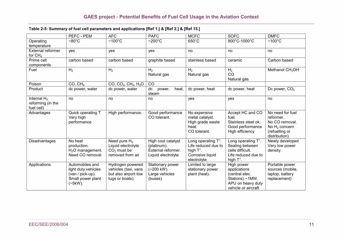
Fortunately pure hydrogen is not the only option to run fuel cells. However, each fuel cell category has specific fuel requirements as highlighted in . The only exception concerns sulphur compounds which are poisonous for every fuel cell [Ref 14.]. The following summarises the various types of fuel cells and their parameters. Also some typical applications are listed, most of them being already developed even though not commercialised.
GAES project - Potential Benefits of Fuel Cell Usage in the Aviation Context
EEC/SEE/2006/004 11
Table 2-5: Summary of fuel cell parameters and applications [Ref 1.] & [Ref 2.] & [Ref 15.]
PEFC - PEM AFC PAFC MCFC SOFC DMFC Operating temperature
~80°C ~100°C ~200°C 650°C 800°C-1000°C ~100°C
External reformer for CH4
yes yes yes no no no
Prime cell components
carbon based carbon based graphite based stainless based ceramic Carbon based
Fuel H2
H2
H2 Natural gas
H2 Natural gas
H2 CO Natural gas
Methanol CH3OH
Poison CO, CH4 CO, CO2, CH4, H2O CO Product dc power, water dc power, water dc power, heat,
steam dc power, heat dc power, heat Dc power, CO2
Internal H2 reforming (in the fuel cell)
no no no yes yes no
Advantages Quick operating T Very high performance
High performance. Good performance CO tolerant.
No expensive metal catalyst. High grade waste heat. CO tolerant.
Accept HC and CO fuel. Stainless steel ok. Good performance High efficiency
No need for fuel reformer. No CO removal. No H2 concern (refuelling or distribution)
Disadvantages No heat production. H2O management. Need CO removal.
Need pure H2 Liquid electrolyte CO2 must be removed from air
High cost catalyst (platinum). External reformer. Liquid electrolyte
Long operating T°. Life reduced due to high T°. Corrosive liquid electrolyte
Long operating T°. Sealing between cells difficult. Life reduced due to high T°.
Newly developed Very low power density
Applications Automobiles and light duty vehicles (van / pick-up). Small power plant (~5kW).
Hydrogen powered vehicles (taxi, vans but also airport tow tugs or boats).
Stationary power (~200 kW). Large vehicles (buses)
Limited to large stationary power plant (heat).
High power applications (central elec. Stations) ~1MW. APU on heavy duty vehicle or aircraft.
Portable power sources (mobile, laptop, battery replacement)

GAES project - Potential Benefits of Fuel Cell Usage in the Aviation Context
12 EEC/SEE/2006/004
2.4 Fuel Cells Applications in the Airport Context
The potential benefits of fuel cells in the airport / aviation domain are expected to be numerous, especially in the current context of emission reduction and fuel consumption reduction. Each airport activity has its specific requirements depending on the energy it requires or the level of safety it necessitates. This section attempts to list the valid fuel cell categories that could be used instead of traditional power sources taking into consideration the specificity of airport activities based on an extensive literature review.
2.4.1 Auxiliary Power Unit
A current challenge of aviation is to reduce its impact on the environment by reducing the fuel it consumes and at the same time the emissions released, and especially NOx. Aircraft APU is an area which has been identified as very suitable for fuel cells by major aircraft manufacturers such as Airbus (CELINA project) [Ref 4.], Boeing [Ref 16.] & [Ref 18.] and NASA (NEXCAP project) [Ref 19.]. Aircraft APU need to run on jet fuel, therefore SOFC would be a convenient choice due to their capacity to handle "dirty hydrogen" produced from kerosene reforming. However, in case a H2 source is available on-board the aircraft, PEMFC could be more efficient [Ref 17.]. These would be especially beneficial in the case of hydrogen fuelled aircraft. In that case the fuel cell would only exhaust pure water and warm air [Ref 18.], both of which could be used onboard the aircraft [Ref 17.] & [Ref 22.]. However, hydrogen aircraft are not expected to be developed before 20 to 50 years unless surprising technological breakthroughs occur [Ref 20.]. There are driving forces that push for the development of APU fuel cells. For example, the Boeing project of a More Electrical Aircraft (MEA) would greatly benefit from fuel cell generated electricity [Ref 16.]. The aim of the MEA project is to make greater use of electrical power on-board an aircraft. This is expected to reduce fuel consumption, as electricity generated by an APU (a fortiori a FC APU) could be used. The range of applications is huge: cabin pressurization, environment control system, lighting, cockpit instrumentation, wing anti-ice protection, control surface and landing gear actuation i.e. all the main energy consumers on-board [Ref 18.]. In order to maximise fuel cell efficiency, some developments in aircraft components would be of great interest, such as the weight reduction of the landing gear between others as explained in [Ref 22.] and [Ref 23.]. Boeing stated in [Ref 16.] that the use of a SOFC APU in the MEA context is estimated to reduce aircraft APU fuel consumption during cruise by 40% and on the ground by 75% (estimations for standard sea level conditions). Accordingly, it was estimated in the course of the CRYOPLANE European Project [Ref 20.] that kerosene SOFC APU would reduce aircraft ground NOx by 80%. Moreover, according to NASA [Ref 19.], traditional gas turbine APU is responsible for 20% of aircraft ground emissions and 50% of maintenance delays (which account for 12% of maintenance costs). Those figures are expected to be reduced when using SOFC as they have solid state characteristics, providing new developments enhance their robustness. The actual demonstrated fuel cell power density is about 0.3 kW / kg. Boeing and Airbus both estimated in [Ref 4.] and [Ref 16.] that FC need to reach a power density about 1 kW / kg in order to be acceptable on-board an aircraft. The counter-part of a heavy fuel cell is the subsequent increase in the in-flight fuel consumption (and thus in emissions) to carry over the FC APU during the aircraft trip. However no detailed figure was available that would allow for an estimate of the extra fuel consumption as a consequence of a heavy fuel cell. Development efforts are necessary so that the use of FC APU is viable. However this report focuses on the actual applications of APU, i.e. on the ground applications.
GAES project - Potential Benefits of Fuel Cell Usage in the Aviation Context
EEC/SEE/2006/004 13
Due to the high safety required when dealing with an aircraft power system, some key design issues need serious considerations. Main ones are listed below (from [Ref 4.] & [Ref 20.]):
• Safe aircraft operations
• Fire protection, detection and extinguishing
• Fuel supply
• Fuel and APU control units (hydrogen metering could be a problem)
• Engine operations (fuel system need purge and cooling before start)
• APU fuel necessitates approximately a 1m sphere for 3 hours of operation
• Compartment (APU should run as a separate H2 consumer)
Regardless of the public and passenger acceptance which could be a hurdle, the utilisation of fuel cells APU is also facing technical obstacles which are not solved yet. First of all, they need size and weight reduction (i.e. a higher power density) as reported by Airbus [Ref 4.], Boeing [Ref 16.] and Canada Air Transports [Ref 22.] to reach acceptable levels. The current robustness and reliability of SOFC is also a challenge, especially considering the wide range of ambient conditions under which they must operate [Ref 4.]. At 41 000 feet, the pressure is around 0.2 bar and the temperature is -56°C and even -78°C at 50 000 feet [Ref 21.]. Finally the operations of fuel cells in the upper atmosphere will generate more contrails than traditional APU as the exhausts are composed of water and hot air [Ref 22.]. No detailed figure was available in the literature to quantify the extent of those additional contrails. Last but not least, economical considerations are likely to be a hurdle for the use of APU fuel cells on a large scale [Ref 16.] & [Ref 23.]. As a results of the great benefits that could be generated by the use of APU SOFC, both Airbus (Germany) and Boeing launched project with the aim of developing H2 fuelled APU prototypes, using respectively a an Airbus 300-600ST (Beluga) and a Boeing 737 [Ref 20.]. Boeing prototype is expected to be ready by 2010 for an expected commercialisation in 2015 [Ref 9.] & [Ref 18.].
2.4.2 Airport Power Plants
Generating electrical power in stationary sources is the most mature fuel cells application. Nearly all categories of fuel cells are suitable for this duty: PAFC, AFC, PEFC, MCFC, and SOFC [Ref 1.] & [Ref 2.] & [Ref 15.]. It is stated that the operation cost of such plants are reduced between 20% and 40% compared with conventional energy services. Such systems have been put in place in a wide range of facilities: hospitals, municipal buildings, utility power plants and also airport terminals in order to provide primary or back-up power. PAFC remained the usual choice for large scale application, but more recently MCFC and SOFC have also proved their applicability [Ref 2.] & [Ref 15.]. Note that MCFC and SOFC are the most resistant fuel cells, and as such they can handle a wider variety of fuels (and qualities of fuel) than other fuel cells. Fuel cells have a decisive role to play in many applications where electricity is used:
• Small power 1 - 5 kW / 5-10 kW
• Medium power 10 -100 kW / 50 - 300 kW
• Large power 250 kW - 10 MW
Fuel cells are at their optimum when dealing with medium to large power requirements, which is what is required in the case of airport. An advantage of fuel cell stationary sources is their high efficiency when compared with traditional fuel plants (above 40% for most categories). Moreover, their gaseous exhaust can be re-used with micro-turbines generating thereby even higher efficiencies [Ref 2.] & [Ref 15.].
GAES project - Potential Benefits of Fuel Cell Usage in the Aviation Context
14 EEC/SEE/2006/004
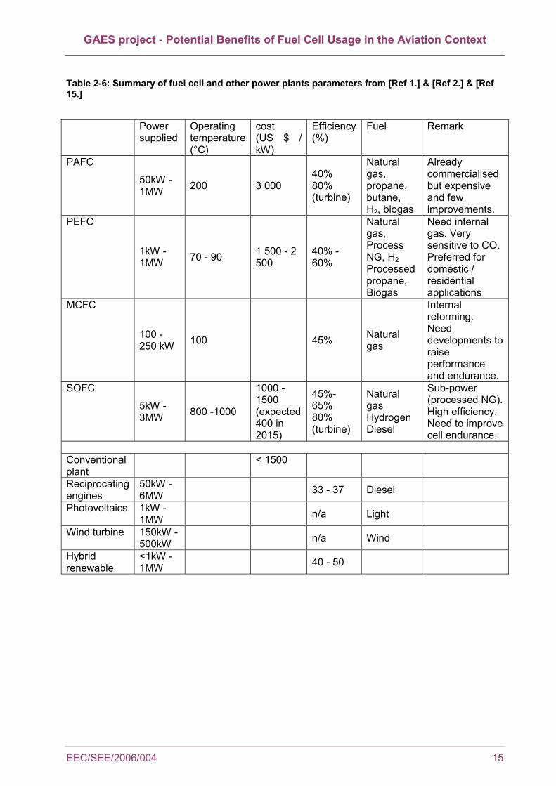
The use of fuel cells as emergency power units is widely reported in the literature. That is because once started, they provide power continuously, and are often referred as uninterrupted power supply [Ref 15.]. A drawback is that they need start-up batteries (esp. PEFC and SOFC). From [Ref 1.], [Ref 2.] & [Ref 15.] the following table () summarises the attributes of power plants depending on the fuel cell category applied. The choice for one or the other fuel cell category relies on the type and quantity in kW of power required (i.e. primary or back-up). Construction costs expressed in US $ per kW have also been collected whenever possible. Also the power obtainable and the efficiency of some other power plants has been included for comparison purposes. From [Ref 1.], the most powerful and efficient system is hybrid fuel cell / gas turbine. A further benefit is that old existing plant (coal gasifiers especially) could be re-powered with high temperature fuel cells (MCFC or SOFC), re-using the heat from the fuel cells to generate steam for the existing plant's turbines. Such plants have been demonstrated to operate at efficiencies around 60%. However there are some challenges to overcome before fuel cell commercialisation. Firstly, the cost issue. The price of producing fuel cells remains high, especially as several design necessitate expensive precious metals catalysts while other require costly materials which are resistant to extremely high temperatures. Fuel cells also need further improvements in durability which call for new design and materials. Finally the infrastructure to produce and store hydrogen is still at a low state of development and hydrogen remains more expensive to produce than other conventional fuels [Ref 1.], [Ref 2.] & [Ref 15.].
GAES project - Potential Benefits of Fuel Cell Usage in the Aviation Context
EEC/SEE/2006/004 15
Table 2-6: Summary of fuel cell and other power plants parameters from [Ref 1.] & [Ref 2.] & [Ref 15.]
Power
supplied Operating temperature (°C)
cost (US $ / kW)
Efficiency(%)
Fuel Remark
PAFC
50kW - 1MW 200 3 000
40% 80% (turbine)
Natural gas, propane, butane, H2, biogas
Already commercialised but expensive and few improvements.
PEFC
1kW - 1MW 70 - 90 1 500 - 2
500 40% - 60%
Natural gas, Process NG, H2 Processed propane, Biogas
Need internal gas. Very sensitive to CO. Preferred for domestic / residential applications
MCFC
100 - 250 kW 100 45% Natural
gas
Internal reforming. Need developments to raise performance and endurance.
SOFC
5kW - 3MW 800 -1000
1000 - 1500 (expected 400 in 2015)
45%-65% 80% (turbine)
Natural gas Hydrogen Diesel
Sub-power (processed NG). High efficiency. Need to improve cell endurance.
Conventional plant
< 1500
Reciprocating engines
50kW - 6MW 33 - 37 Diesel
Photovoltaics 1kW - 1MW n/a Light
Wind turbine 150kW - 500kW n/a Wind
Hybrid renewable
<1kW - 1MW 40 - 50
GAES project - Potential Benefits of Fuel Cell Usage in the Aviation Context
16 EEC/SEE/2006/004
2.4.3 Airport Special Vehicles & Airside Road Vehicles
Fuel cells can be used as generator, battery charges or battery replacement [Ref 1.]. Fuel cells have a decisive role to play where electricity is used [Ref 15.] which can be the case for virtually any vehicle used on the apron. Due to their high operating temperatures, PACFC, MCFC and SOFC are in most cases not suitable for primary propulsion. It is generally accepted that SOFC are better for Auxiliary Power Unit for heavy duty vehicles (truck, buses…). That is because SOFC need additional space to allow for a thermal management unit due to high operating temperatures (600-800°C). A subsequent advantage is the generation of heat that can be re-used on-board the vehicle [Ref 1.]. On the contrary, PEMFC are widely used for primary propulsion by automotive manufacturers [Ref 24.]. They have two major drawbacks: first they require some sort of water management and a radiator, and second they can only cope with clean fuel which means a fuel processing unit is necessary if gasoline is to be used [Ref 1.]. From the "Fuel Cell Vehicle World Survey 2003" [Ref 25.], it is noticed that all major automotive constructors worldwide undertook research about the applications of fuel cells to the automotive industry. Companies involved, between others are BMW, DaimlerChrysler, Fiat, Ford, GM, Honda, Hyundai, Mazda, Mitsubishi, Nissan, PSA Peugeot Citroen, Renault, Toyota, Volkswagen AG… It resulted in fuel cell prototypes for most terrestrial vehicles, i.e. personal cars, light duty vehicle (van / pickup), heavy duty vehicle (buses / trucks) and even special vehicles such as tractors. A very wide range of fuels and fuel cells have been tested. PEMFC appeared the most convenient way to propel personal cars and light duty vehicles and in some cases heavy duty vehicles such as buses [Ref 23.]. The interests of fuel cell for automotive propulsion are again the same as for APU or stationary sources: they provide power indefinitely and have virtually no maintenance cost while fuelled with hydrogen and oxygen. Additionally they have high energy conversion efficiency [Ref 26.]. They can reach up to 60% efficiency which is very high when compared with conventional gasoline engine (20%) [Ref 23.]. Fuel cell transport applications belong to two types: direct fuel cell vehicle (DFCV) and processed fuel cell vehicle (PFCV) as explained in [Ref 15.]. As indicated by their names, in the DFCV the fuel is stored in the vehicle and directly provided to the fuel cell. On the contrary in the case of a PFCV there must be a fuel processor in the vehicle. Each category has its pros and cons which are expressed in the following paragraphs.
2.4.3.1 Direct Fuel Cell Vehicle DFCV
Fuel in the form of hydrogen or methanol can be directly provided to the DFCV. When H2 is used, the efficiency of the vehicle is doubled compared with methanol. Moreover, the CO2 emissions are two thirds less (for an ICE BMW vehicle) considering obviously the emissions due to the production of H2 (otherwise the CO2 emissions would be null) [Ref 15.]. The immediate issue concerning DFCV is that infrastructure for the production and the distribution of the fuel is necessary. This is true for both methanol and H2. Hydrogen storage issues were already discussed in 2.3. To summarise, the three ways to store hydrogen (high pressure, cryogenic, metal hydrides) require significant investments and technological improvements. Concerning methanol, it is reported in [Ref 27.] that "the existing gasoline retail distribution system can be adapted to serve methanol with few modifications." Usually, methanol is obtained from natural gas and it is liquid under atmospheric conditions (pressure and temperature). The storage of H2 remains the main problem for vehicle storing it on-board. Each one of the three storage method necessitates large volume vessels, limiting its use to heavy duty vehicles such as buses or trucks. Another issue, in the case of direct methanol fuel cell, is the fuel crossover in the membrane which lowers the efficiency of the fuel cell.
GAES project - Potential Benefits of Fuel Cell Usage in the Aviation Context
EEC/SEE/2006/004 17
2.4.3.2 Processed Fuel Cell Vehicle
This type of vehicles needs a fuel reforming unit on-board (also called fuel processor) in order to generate a fuel that is clean enough to be used in fuel cells. This is especially true for PEMFC as it allows them to use transportation fuel (esp. gasoline) [Ref 1.]. Since a fuel processor is on-board a wide variety of fuels can be used: methanol, propane, and gasoline between other fuels are suitable. Obviously the efficiency of the device depends on the type of fuel use: the option of using gasoline would be cheaper but in the mean time the efficiency would be lower [Ref 15.] However, the most problematic area is the sensitivity of the fuel processor towards CO. If CO is present in the fuel processor, performances of the fuel cell will decrease quickly. Hence, there is a need for complete removal of CO in the fuel which implies higher weight, volume and cost of the fuel cell [Ref 15.]. There are also technological issues linked to the development of PFCV, the main one being the difficulty to integrate the fuel processor to the fuel cell stacks as reported in [Ref 15.]. A subsequent problem is the long start up time (5 minutes). It must be acknowledged that for both DFCV and PFCV, the fuel provided to the fuel cell must be cleaned of all sulphur and sulphur compounds. In the case of DFCV, the sulphur removal device has to be located prior the fuel storage unit, while for PFCV additional weight and volume it needs to be on-board with the subsequent disadvantages in terms of weight and volume [Ref 15.].
2.4.3.3 Aircraft Handling Vehicles
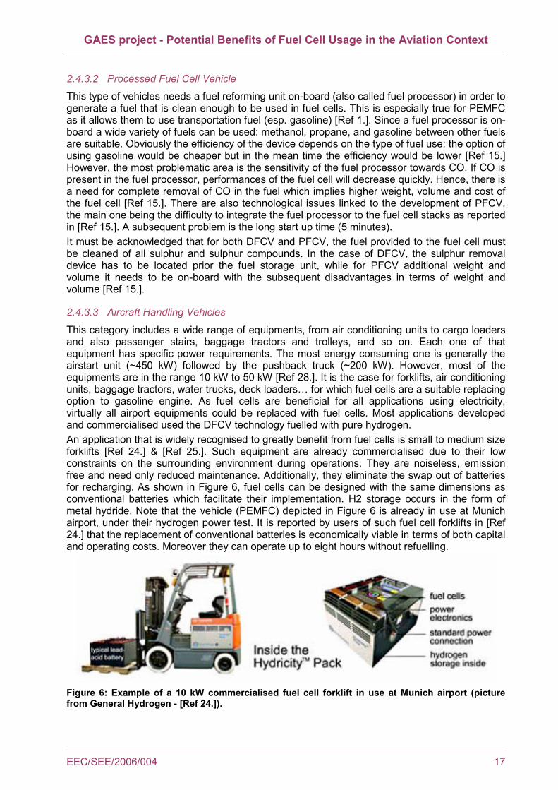
This category includes a wide range of equipments, from air conditioning units to cargo loaders and also passenger stairs, baggage tractors and trolleys, and so on. Each one of that equipment has specific power requirements. The most energy consuming one is generally the airstart unit (~450 kW) followed by the pushback truck (~200 kW). However, most of the equipments are in the range 10 kW to 50 kW [Ref 28.]. It is the case for forklifts, air conditioning units, baggage tractors, water trucks, deck loaders… for which fuel cells are a suitable replacing option to gasoline engine. As fuel cells are beneficial for all applications using electricity, virtually all airport equipments could be replaced with fuel cells. Most applications developed and commercialised used the DFCV technology fuelled with pure hydrogen. An application that is widely recognised to greatly benefit from fuel cells is small to medium size forklifts [Ref 24.] & [Ref 25.]. Such equipment are already commercialised due to their low constraints on the surrounding environment during operations. They are noiseless, emission free and need only reduced maintenance. Additionally, they eliminate the swap out of batteries for recharging. As shown in Figure 6, fuel cells can be designed with the same dimensions as conventional batteries which facilitate their implementation. H2 storage occurs in the form of metal hydride. Note that the vehicle (PEMFC) depicted in Figure 6 is already in use at Munich airport, under their hydrogen power test. It is reported by users of such fuel cell forklifts in [Ref 24.] that the replacement of conventional batteries is economically viable in terms of both capital and operating costs. Moreover they can operate up to eight hours without refuelling.
Figure 6: Example of a 10 kW commercialised fuel cell forklift in use at Munich airport (picture from General Hydrogen - [Ref 24.]).

GAES project - Potential Benefits of Fuel Cell Usage in the Aviation Context
18 EEC/SEE/2006/004
According to [Ref 24.], fuel cell would work for any power small vehicle (< 20kW). In the case of airport, that would include luggage trucks, ACU, ambulift, flatbed, baggage loaders, water trucks, small tank fuel trucks… on top of forklifts. Luggage trolley powered by fuel cell has been recently developed by H2 Logic (Denmark) and is currently tested at a Danish airport. It is expected that most of the airport GSE will have the same issues as light duty vehicles. The power requirement of most of them is way below 100 kW [Ref 28.], and relatively often the same equipments are used on the airport and in public areas (e.g. catering trucks, water supply and disposal trucks…). Other applications (such as lawnmowers, wheelchairs, trains, ships APU or scooters) prove that the field of application for fuel cells is huge.
2.4.3.4 Bus / trucks / GPU (Heavy Duty Vehicles)
From the Fuel Cell Vehicle World Survey 2003 [Ref 25.], fuel cells have been used to power buses in a dozen projects worldwide. Most of the prototype buses use PEMFC either on a stand alone matter or assembled in stacks. Power delivered by such fuel cells ranges from 78 kW up to 200 kW. In some cases, hybrid systems are used in the form of additional battery to provide more power to the buses to climb hills for example. Capacity in terms of passengers was between 40 and 130 (in the case of a double deck bus). However, the largest number of passengers handled by a fuel cell bus is likely to be around 50. Most prototypes used compressed hydrogen stored in cylinders mounted on the roof of the buses as shown in Figure 7. Only one project was found that used methanol, using either a PAFC or a PEMFC both supplying a 100 kW power (Nova Bus, Georgetown University, Washington DC) [Ref 25.]. Issues encountered when dealing with heavy duty vehicle fuel cell are once again about weight, size and operating cost of the installation. It is worth noticing that the problem with operating cost is mainly due to the infrastructure necessary to generate and distribute hydrogen [Ref 25.].
Figure 7: Example of the Toyota hybrid fuel cell bus (90 kW fuel cell stacks) from [Ref 25.].
Due to the specificity of some airport equipments, most of them have not yet been tested using prototypes. However, it is expected that the benefits (and also the problems) would be similar to the ones met for usual vehicles. There are of course technical issues as obviously the design of a fuel cell to replace a GPU or a pushback tug engine would not the same as for a bus, even though the power required is similar (~200 kW). The fact that fuel cell bus prototypes are working well establish that providing 200 kW power is not an issue for mobile fuel cells. However, no specific project dealing with airport mobile machinery and fuel cells was found at the time of this study.
GAES project - Potential Benefits of Fuel Cell Usage in the Aviation Context
EEC/SEE/2006/004 19
Keeping in mind the above considerations, there is one airport equipment that requires specific treatment due to its high power demand (~450 kW from [Ref 28.]): the mobile airstart unit. It is providing compressed air to the aircraft’s engine for start up. There was no reference in the literature to the development of such high power mobile device using fuel cell.
2.4.3.5 Airport Hydrogen Projects
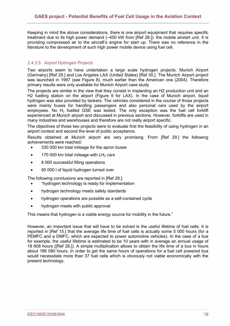
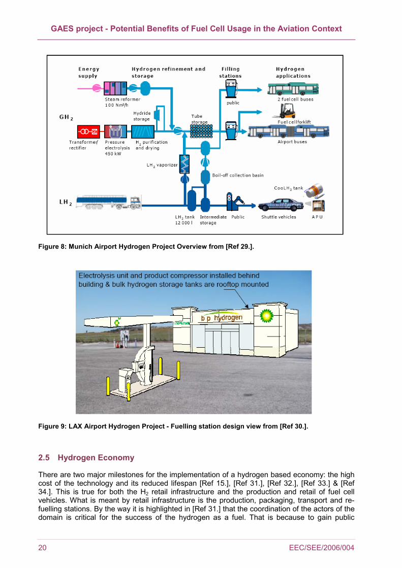
Two airports seem to have undertaken a large scale hydrogen projects: Munich Airport (Germany) [Ref 29.] and Los Angeles LAX (United States) [Ref 30.]. The Munich Airport project was launched in 1997 (see Figure 8), much earlier than the American one (2004). Therefore primary results were only available for Munich Airport case study. The projects are similar in the view that they consist in implanting an H2 production unit and an H2 fuelling station on the airport (Figure 9 for LAX). In the case of Munich airport, liquid hydrogen was also provided by tankers. The vehicles considered in the course of those projects were mainly buses for handling passengers and also personal cars used by the airport employees. No H2 fuelled GSE was tested. The only exception was the fuel cell forklift experienced at Munich airport and discussed in previous sections. However, forklifts are used in many industries and warehouses and therefore are not really airport specific. The objectives of those two projects were to evaluate first the feasibility of using hydrogen in an airport context and second the level of public acceptance. Results obtained at Munich airport are very promising. From [Ref 29.] the following achievements were reached:
• 330 000 km total mileage for the apron buses
• 170 000 km total mileage with LH2 cars
• 8 000 successful filling operations
• 60 000 l of liquid hydrogen turned over
The following conclusions are reported in [Ref 29.]: • “hydrogen technology is ready for implementation
• hydrogen technology meets safety standards
• hydrogen operations are possible as a self-contained cycle
• hydrogen meets with public approval
This means that hydrogen is a viable energy source for mobility in the future.” However, an important issue that will have to be solved is the useful lifetime of fuel cells. It is reported in [Ref 15.] that the average life time of fuel cells is actually some 5 000 hours (for a PEMFC and a DMFC, which are expected to power automotive vehicles). In the case of a bus for example, the useful lifetime is estimated to be 10 years with in average an annual usage of 18 608 hours ([Ref 28.]). A simple multiplication allows to obtain the life time of a bus in hours about 186 080 hours. In order to get the same hours of operations for a fuel cell powered bus would necessitate more than 37 fuel cells which is obviously not viable economically with the present technology.
GAES project - Potential Benefits of Fuel Cell Usage in the Aviation Context
20 EEC/SEE/2006/004
Figure 8: Munich Airport Hydrogen Project Overview from [Ref 29.].
Figure 9: LAX Airport Hydrogen Project - Fuelling station design view from [Ref 30.].
2.5 Hydrogen Economy
There are two major milestones for the implementation of a hydrogen based economy: the high cost of the technology and its reduced lifespan [Ref 15.], [Ref 31.], [Ref 32.], [Ref 33.] & [Ref 34.]. This is true for both the H2 retail infrastructure and the production and retail of fuel cell vehicles. What is meant by retail infrastructure is the production, packaging, transport and re-fuelling stations. By the way it is highlighted in [Ref 31.] that the coordination of the actors of the domain is critical for the success of the hydrogen as a fuel. That is because to gain public
GAES project - Potential Benefits of Fuel Cell Usage in the Aviation Context
EEC/SEE/2006/004 21
acceptance, both the commercialization of hydrogen vehicles and the development of a supporting hydrogen infrastructure need to be ready at the same time. It is reported in [Ref 31.] that hydrogen has to be available at one fourth of refill stations so that it would be acceptable to use it for people. It can be feared that no party will act first. Consequently incentives from governments and clear business actions are necessary to stimulate the growth of a sustainable hydrogen industry [Ref 31.] & [Ref 32.]. Actions could consist in drawing appropriate H2 fiscal policies through the introduction of hydrogen tax incentives or subsidiaries to help technological developments. The issues to solve are then triple: technical, economic and also politic. The foreseen applications of fuel cells on a large scale in the short-medium term are terrestrial vehicles and stationary power plants [Ref 33.]. Fuel cell prototype vehicles have been developed worldwide for personal cars, light duty vehicles and also buses and trucks. Considering power plants, commercial applications are already available for residential use that combine heat and power production [Ref 33.]. Industrial use of fuel cells is also widely reported. Concerning aviation it should be noted that only very few projects were found at the time of writing of this report (Boeing and Airbus APU [Ref 16.] & [Ref 20.]). Subsequent prototypes are under development and no results have been published yet, not to mention hydrogen fuelled aircraft. Some say hydrogen technology will be ecologic, economic and technically feasible in 20 year times [Ref 31.] & [Ref 33.]. However, reserves are emitted by others that would not even risk themselves to publish a timescale. That is because the issues to solve are numerous. First, if pure hydrogen is to be available at refill stations environmental issues about hydrogen production need solutions. Currently, H2 production has three origins: fossil fuels, nuclear fission and renewable energies [Ref 31.], [Ref 34.] & [Ref 35.]. The use of fossil fuels to create hydrogen is unacceptable as it would still exhaust CO2 in the atmosphere annihilating thereby positive effect of H2. Even if carbon sequestration devices were to be used, the problem of CO2 storage would remain: it is costly (roughly 100 to 200 US $ per ton of C [Ref 34.]) and needs available closed spaces. Most important the CO2 from only 30% of the energy used to produce H2 could be captured [Ref 34.]. The by-product of nuclear fission is highly radioactive elements, which is not acceptable either from an environmental point of view. Finally hydrogen production from renewable energies is shown in Table 2-7 to be too expensive to be viable at the present time. Table 2-7: Hydrogen production costs in US dollars of 1990 from [Ref 32.].
Type of energy Cost of H2 production (1990 US $ per kWh)
Biomass 510 Coal 515 Electricity 500 Natural Gas 250 Oil based 500 Solar 2 900
From Table 2-7 the cheapest process to produce hydrogen would be from natural gas. As highlighted in [Ref 31.] large scale and centralised plants would be the most efficient. The second point is hydrogen distribution. It is acknowledged that at the moment the cheapest way to transport hydrogen is through road trucks in its liquid form [Ref 31.]. Therefore it is not the best solution environmentally speaking. However, it is reported in [Ref 34.] that the cost of transporting compressed hydrogen with pipelines and liquefied hydrogen by road is roughly the same. Note that the cost of building and operating the pipelines are accounted for in that estimation as well as the cost of compressing hydrogen. It should be bear in mind that hydrogen distribution and refilling costs are site specific, and also depend on the density of hydrogen vehicles and the scale of production plants [Ref 34.]. Finally, reserves are emitted when dealing with cost figures as they vary hugely depending on the assumptions made by the modellers.

GAES project - Potential Benefits of Fuel Cell Usage in the Aviation Context
22 EEC/SEE/2006/004
It is then possible to conclude that at present, H2 is not cost-efficient nor environmentally. It is doubtful that this will change in next years unless new discoveries and innovations in the field are made [Ref 34.]. The use of fuel reformers on-board fuel cell applications would be an alternative to expensive and long term H2 investments. But there are still technological and economic issues related to on-board fuel reforming even though it eliminates the H2 problems. Considering aircraft APUs, such internal reforming introduces additional APU technical complexity and technical risk. For example, APU fuel cell would need on-board highly efficient sulphur removal devices due to the high sulphur content of kerosene [Ref 3.]. Those are likely to raise again the cost of APU fuel cells. In the mean time, aviation is likely to benefit from all innovations discovered when dealing with fuel cell for mobile and stationary applications which is likely to reduce costs. If road transport goes to hydrogen, then the infrastructure would become affordable for airports. Airport may invest in a hydrogen infrastructure as an "environmental" policy once it becomes affordable. But the slow maturation of H2 technologies [Ref 31.] remains an issue…
GAES project - Potential Benefits of Fuel Cell Usage in the Aviation Context
EEC/SEE/2006/004 23
3 CASE STUDY
3.1 Method
The case study focuses on a real case study airport located in Eastern Europe. The case study presented thereafter considers the replacement of gas turbine (GT) APU by fuel cell (FC) APU only. Only APU ground emissions are covered. Other applications of fuel cells than APU are not investigated due to the lack of data concerning the behaviour of those sources on the airport (GSE, road traffic or stationary sources). It is assumed that the FC APU usage would be similar to the use made of GT APU today. Moreover, in-flight fuel burnt and emissions increases as a result of a heavier FC APU than a GT APU was not evaluated here. It is expected that FC will not be implemented on aircraft unless their performance in terms of power density become similar to the ones of APU.
Exact taxiing times have been monitored at this airport and therefore were available for each movement on the apron over the year 2004, in line with the aircraft type. The airport is a two crossing runway airport with about 120,000 movements in 2004. Average taxiing time is below ten minutes; therefore it can be assumed that the APU is started as soon as the aircraft exits the runway. Further information about the airport considered during this case study is available upon request to the authors.
In parallel, emission factors to estimate emissions for current technology APU could be extracted from two sources: EDMS v4.3 [Ref 43.] and LASPORT v1.5 [Ref 44.]. Both sources provide between others NOx, CO and HC emission factors. In addition, fuel flow is available in LASPORT, making possible the estimation of fuel directly proportional emissions, namely CO2, H2O and SOx.
Finally, based on efficiency data of gas turbine (GT) based APU, fuel usage from the fuel cell (FC) APU is considered as a direct fuel ratio of their respective efficiencies (i.e. 3 kg of fuel in GT APU = 1 kg in FC APU if the efficiencies are 15% and 45% respectively, for a given power and duration). APU emission factors for fuel cell are derived from the equation of the overall reaction for the complete conversion of aviation fuel (see section 3.2.1).
All this information was combined in order to indicate NOx, CO, HC, CO2, H2O and SOx emission factors corresponding to each movement on the airport in 2004.
Emissions amount were estimated as follows:
3.2 Emission amount = APU operating time x emission factor
3.2.1 Emission factors
EDMS emission factors are APU specific. NOx, CO and HC emission factor for 29 different APU were available in the original software. In addition, EDMS holds a list of APU generally installed on aircraft. This list was used to determine APU installed on aircraft operating at the airport, and consequently corresponding emission factors. LASPORT provides NOx, CO and HC emission factors based on the official aircraft grouping from German Airports association for airport noise assessment AzB. In addition, fuel flow is accessible. ICAO aircraft grouping (from ALAQS-AV) was used to link LASPORT emission factors to the airport's movements [Ref 36.]. The difference between LASPORT and EDMS APU emissions is shown in Figure 10. This difference is due to the methods used to define APU emission factors. Indeed, while emission factors are expressed for 29 different APU types in EDMS, LASPORT uses emission factors per

GAES project - Potential Benefits of Fuel Cell Usage in the Aviation Context
24 EEC/SEE/2006/004
aircraft groups (according to the AzB classification). In addition a table is provided in EDMS that links each aircraft to the mostly used APU. Figure 10 brings out the overestimation of EDMS regarding LASPORT emission factors for CO and HC. The opposite tendency is observed for NOx, but to a lesser extent. This observation confirms the necessity of using an average of EDMS and LASPORT values for analysing the results inherent to this case study.
NOx EDMS
NOx LASPORT
CO EDMS
CO LASPORT
HC EDMS
HC LASPORT0
2
4
6
8
Tonn
es
NOx EDMSNOx LASPORTCO EDMSCO LASPORTHC EDMSHC LASPORT
Figure 10: Comparison of "scenario 1" emissions in 2004.
The emission factors considered in the case study relate to the emissions generated by the run of the fuel cell only as opposed to the ones of the total life cycle of the device. Specific details of emission factors of FC APU are very system specific. Nevertheless a general approach leads to global emission factors. The emission levels for fuel cell APUs are principally dependant upon the reformer system and the fuel supplied to it. For example, the overall reaction for the complete conversion of aviation fuel is as follows:
C11.6H22.3 + 17.175O2 = 11.6CO2 + 11.15H2O All of the carbon contained within the fuel will ultimately be converted into CO2 after passing through the reformer and SOFC (or shift reactors in the case of a PEFC system). In consideration of the chemical equation above, 1 kg of Jet Fuel will be consumed by the FC APU to produce 3.15 kg of CO2 and 1.24 kg of water. Assuming a 45% overall FC APU efficiency compared to a GT APU efficiency of 15%, the FC APU will produce one third of the amount of CO2 for an equivalent power and operating duration. In practice, some fuel gas is allowed to pass through the fuel cell in order to sweep out diluents gases (nitrogen). This excess fuel can either be burnt to produce heat or recycled back into the reformer and so little hydrogen emission should occur. Fuel additives within the jet fuel are comprised of compounds containing C, N, and O and therefore will have no impact on the emissions levels from the APU. Sulphur containing species will be reformed and the free sulphur converted into H2S prior to being trapped out in a zinc oxide (ZnO) adsorbent bed and so no sulphur emissions will occur. Some advanced sulphur trap systems employ auto regeneration in which the sulphur is converted to SO2 and flushed out of the reactor and so if this type of trap is employed, then localised periodic emission of SO2 will occur.

GAES project - Potential Benefits of Fuel Cell Usage in the Aviation Context
EEC/SEE/2006/004 25
Assuming 450ppm of sulphur in 1 kg of Jet Fuel, then this would be converted into 0.48g of H2S, which would be permanently trapped out on ZnO or be recycled to produce 0.9g of SO2 when the adsorbent was regenerated. A FC APU will produce no NOx emissions whatsoever.
3.2.2 Statistical reliability
It should be noted prior defining in more details that "small size" aircraft (i.e. piston propeller, turboprops and some small or regional jets) are not equipped with APU. The case study presented here will therefore focus on the aircraft which are equipped with APU. Moreover, to allow an estimation of emissions using both EDMS and LASPORT, flight movements were included only when emission factors were available from both sources. As a result, 49,187 out of the 120,964 initial movements were included in the case study, which represents 40.7% of the traffic. An average of almost 135 movements per day is statistically reliable for the case study.
3.2.3 Scenarios Definition
The estimation of APU operating times was based on procedures described in section 2.1. Two extreme scenarios were defined:
• Scenario 1: Shortest APU operating times. This scenario supports the hypothesis that external electricity and air-compressed and conditioning capacities are available from the gate for each aircraft. In this case, APU work during taxi-in (on arrival). For departure it is assumed that APU is switched on for 5 to 10 minutes as reported at Zurich airport [Ref 10.] and by the FAA recommended airport procedures [Ref 11.]. An average value of 7.5 minutes is used for this case study before main engine start (on departure).
• Scenario 2: Longest APU operating times. No external capacity is available at the gates, which means that APU work during taxi-in. In addition, APU keeps running for 30 to 60 minutes [Ref 11.] depending on the duration of handling operations. The value of 30 minutes is used for this case study on arrival as the aircraft fleet flying at the airport under consideration is composed of small to medium aircraft mainly (i.e. short handling times). In the case of departing aircraft, APU are switched on 26 minutes before departure for light and medium aircraft, 65 minutes for heavy aircraft3 (based on ICAO aircraft classification).
The scenarios described above are subject to a number of limitations. For example, the cost of running GPU or APU was not accounted for. Similarly the use of FEGP and extreme weather conditions were not accounted for. The APU usage when aircraft are taxiing with less than all engines was not considered either even though this practice is becoming increasingly common. Additionally, since only APU are considered in the case study, it was not necessary to model fuel cell starting up. This would have to be changed in case fuel cell GPU are considered. In addition, a scenario 3 aimed at addressing the "most probable situation at the airport". Indeed, it is postulated that the actual situation at the airport of interest here is a compromise between the two extreme situations described here above. Based on movement table used for this study, 10 gates were used at the airport in 2004. Gates were defined according to the airport AIP document [Ref 37.]. The airport layout with the name of the gates is shown in Figure 11. The number of movements from and to these gates is summarized in the Table 3-1 below.
3 Best estimate times for APU switch-on are as follows: short-haul aircraft average running time lies at 26 minutes before departure while long-haul aircraft average running time is 65 minutes before departure (data retrieved from a major European airport [Ref 38.]). Destination of flight is not indicated in the movement data from the airport monitoring system. It is thus assumed that bigger aircraft fly the longest trips and medium/light aircraft fly short haul trip.

GAES project - Potential Benefits of Fuel Cell Usage in the Aviation Context
26 EEC/SEE/2006/004
Table 3-1: Yearly number of movement per gate at a specific airport in 2004
GATE Number of arrival
Number of departure
Percentage of all movements (%)
AP3 19 929 21 341 19.33 AP3bis 17 855 17 932 16.24 AP5 13 208 11 943 10.82 AP1 1 403 1 399 1.27 AP4 1 199 1 088 0.99 AP2 666 488 0.44 CARGO 598 595 0.54 AP6 309 279 0.25 AP11 80 91 0.08 Total 55 251 55 160 100
Data at disposal does not hold information on ground equipment of each gate. Neither does it indicate the actual use of GSE/FEGP at the airport. Therefore, assumptions are made on FEGP equipment based on the location of the gate on the airport. A suitable assumption is that AP3 is the only FEGP equipped gate as this gate is the closest to the passenger terminal and it is also the mostly used one as shown in Figure 11. This means that:
• aircraft arriving at gate AP3 run APU during taxi-in only (i.e. arrival scenario 1),
• departures from gate AP3 require APU to be switched on 5 to 10 minutes before main engine start only from [Ref 10.] & [Ref 11.],
• all other arrival and departure operation from all gates but AP3 correspond to scenario 2.
18.7% of the airport's traffic in 2004 used AP3 gate4. The assumption thus estimates that, for scenario 3, scenario 1 is used in 18.7% of the cases and scenario 2 the rest of the time.
4 For simplification reasons, it is considered that the same number of flight arrives at and leaves from gate AP3. The figure used is an average between the number of arrival and departure concerned by gate AP3.
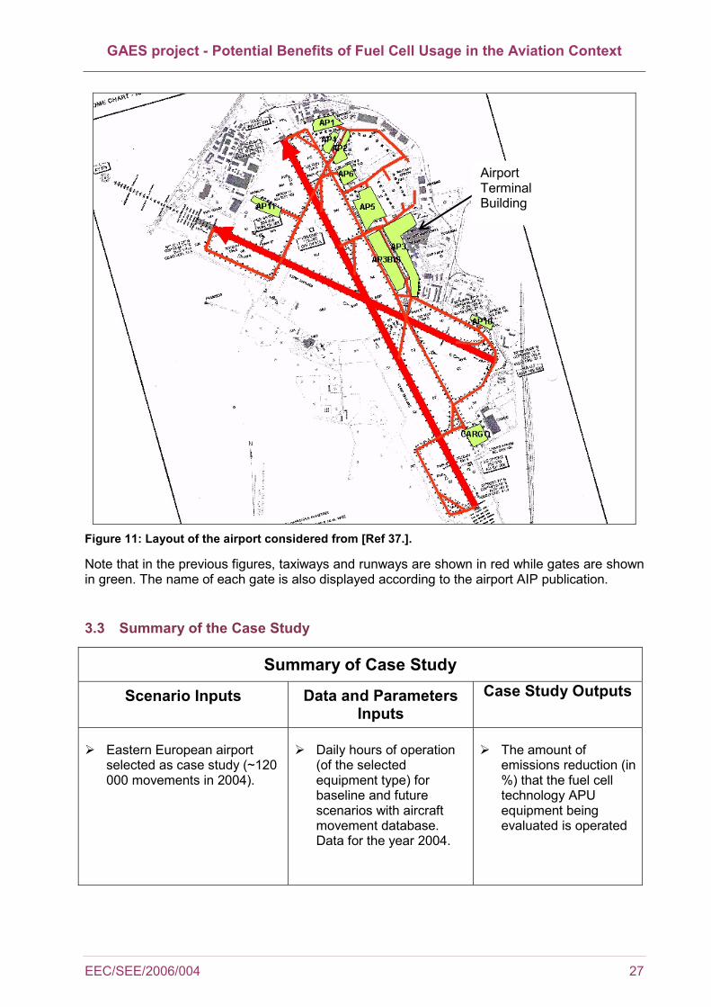
GAES project - Potential Benefits of Fuel Cell Usage in the Aviation Context
EEC/SEE/2006/004 27
Figure 11: Layout of the airport considered from [Ref 37.].
Note that in the previous figures, taxiways and runways are shown in red while gates are shown in green. The name of each gate is also displayed according to the airport AIP publication.
3.3 Summary of the Case Study
Summary of Case Study
Scenario Inputs Data and Parameters Inputs
Case Study Outputs
Eastern European airport selected as case study (~120 000 movements in 2004).
Daily hours of operation (of the selected equipment type) for baseline and future scenarios with aircraft movement database. Data for the year 2004.
The amount of emissions reduction (in %) that the fuel cell technology APU equipment being evaluated is operated
Airport Terminal Building

GAES project - Potential Benefits of Fuel Cell Usage in the Aviation Context
28 EEC/SEE/2006/004
Summary of Case Study
Scenario Inputs Data and Parameters Inputs
Case Study Outputs
APU equipment category being evaluated
The “base” or current technology used in that type of equipment
The fuel cell technologies to be assessed and to be replaced
Expected equipment and engine life (depending on data collected)
Average operational times, emissions factors
Analysis on equipment life, energy and cost issues
3.4 Results
3.4.1 Evolution of emission over one year – GT APU
Figure 12 and Figure 13 present the evolution of NOx and fuel burnt over the year 2004. It was decided to represent NOx emissions rather than HC or CO because NOx is of greater interest when dealing with local air quality. The values calculated using EDMS and LASPORT parameters have been averaged. Only NOx emissions and fuel burnt are represented for the three scenarios defined before. As they are proportional to fuel burn, CO2, H2O and SOx emissions can be deduced from the fuel burn plot. For each day, cumulated emissions (i.e. arrival and departure emissions) are plotted. Pink colour corresponds to scenario 1 while scenario 2 is presented in blue and scenario 3 in yellow.
0
20
40
60
80
01/01
/2004
01/03
/2004
30/04
/2004
29/06
/2004
28/08
/2004
27/10
/2004
26/12
/2004
Kilo
gram
s
NOx scenario 1 NOx scenario 2 NOx scenario 3
Figure 12: NOx emissions in 2004 at the case study airport
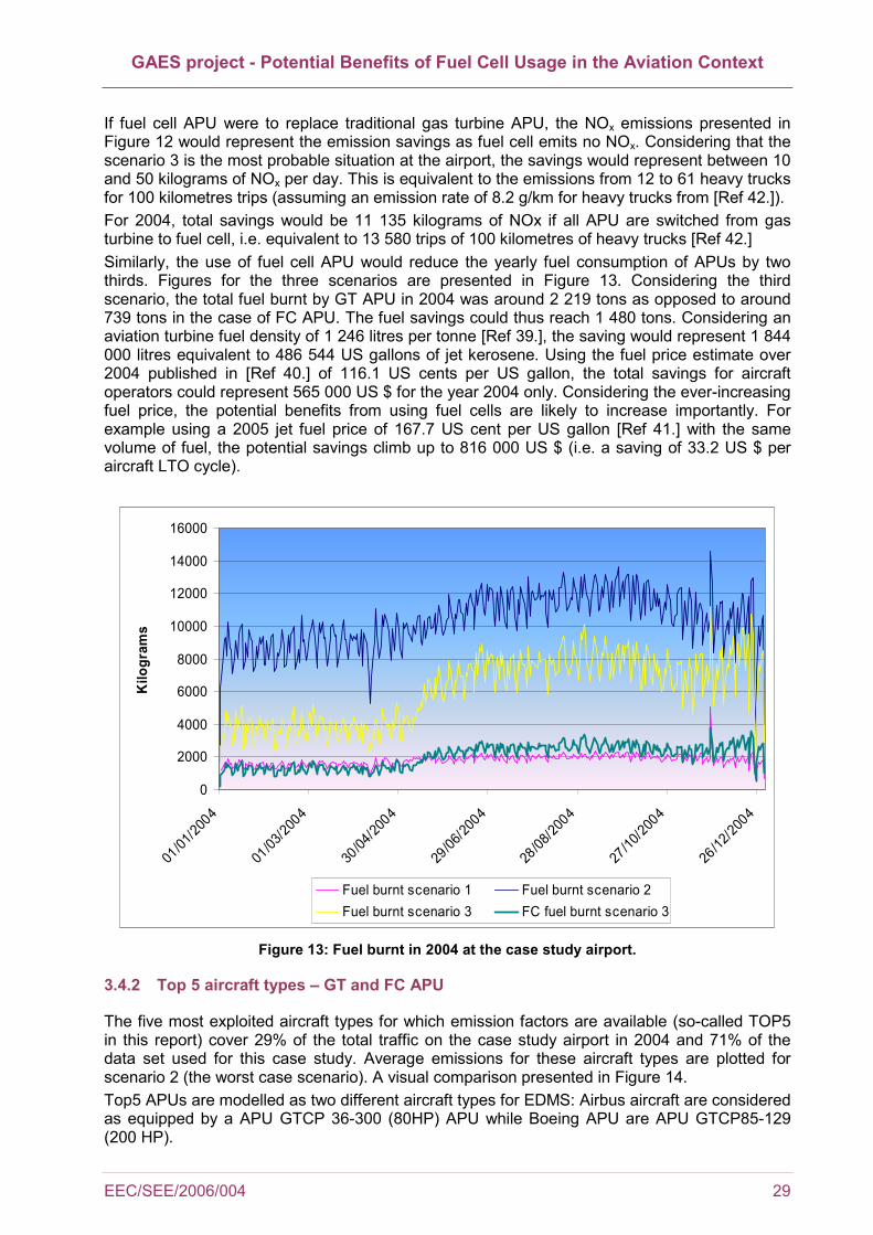
GAES project - Potential Benefits of Fuel Cell Usage in the Aviation Context
EEC/SEE/2006/004 29
If fuel cell APU were to replace traditional gas turbine APU, the NOx emissions presented in Figure 12 would represent the emission savings as fuel cell emits no NOx. Considering that the scenario 3 is the most probable situation at the airport, the savings would represent between 10 and 50 kilograms of NOx per day. This is equivalent to the emissions from 12 to 61 heavy trucks for 100 kilometres trips (assuming an emission rate of 8.2 g/km for heavy trucks from [Ref 42.]). For 2004, total savings would be 11 135 kilograms of NOx if all APU are switched from gas turbine to fuel cell, i.e. equivalent to 13 580 trips of 100 kilometres of heavy trucks [Ref 42.] Similarly, the use of fuel cell APU would reduce the yearly fuel consumption of APUs by two thirds. Figures for the three scenarios are presented in Figure 13. Considering the third scenario, the total fuel burnt by GT APU in 2004 was around 2 219 tons as opposed to around 739 tons in the case of FC APU. The fuel savings could thus reach 1 480 tons. Considering an aviation turbine fuel density of 1 246 litres per tonne [Ref 39.], the saving would represent 1 844 000 litres equivalent to 486 544 US gallons of jet kerosene. Using the fuel price estimate over 2004 published in [Ref 40.] of 116.1 US cents per US gallon, the total savings for aircraft operators could represent 565 000 US $ for the year 2004 only. Considering the ever-increasing fuel price, the potential benefits from using fuel cells are likely to increase importantly. For example using a 2005 jet fuel price of 167.7 US cent per US gallon [Ref 41.] with the same volume of fuel, the potential savings climb up to 816 000 US $ (i.e. a saving of 33.2 US $ per aircraft LTO cycle).
0
2000
4000
6000
8000
10000
12000
14000
16000
01/01
/2004
01/03
/2004
30/04
/2004
29/06
/2004
28/08
/2004
27/10
/2004
26/12
/2004
Kilo
gram
s
Fuel burnt scenario 1 Fuel burnt scenario 2Fuel burnt scenario 3 FC fuel burnt scenario 3
Figure 13: Fuel burnt in 2004 at the case study airport.
3.4.2 Top 5 aircraft types – GT and FC APU
The five most exploited aircraft types for which emission factors are available (so-called TOP5 in this report) cover 29% of the total traffic on the case study airport in 2004 and 71% of the data set used for this case study. Average emissions for these aircraft types are plotted for scenario 2 (the worst case scenario). A visual comparison presented in Figure 14. Top5 APUs are modelled as two different aircraft types for EDMS: Airbus aircraft are considered as equipped by a APU GTCP 36-300 (80HP) APU while Boeing APU are APU GTCP85-129 (200 HP).

GAES project - Potential Benefits of Fuel Cell Usage in the Aviation Context
30 EEC/SEE/2006/004
LASPORT APU emission factors are based on an aircraft grouping (see section 3.4.1). All the 5 aircraft are members of the same group: Jet Small. Indeed, MTOW of the top5 aircraft evolves between 54,686 and 74,284 kg. APUs of these aircraft are thus considered as producing the same amount of emission. CO2, H2O and SOx amounts can be extrapolated linearly from the fuel burnt figures (see factors in 3.2.1), and therefore they present the same variations as fuel. It was decided not to include those additional pollutants in order not to overload the figure. It is noticeable that the aircraft type and consequently the APU type has a great importance for emission calculations: the 200 Hp APU fitting Boeing aircraft emit slightly less NOx (0.31 kg/flight against 0.48 kg/flight for Airbuses) but far more CO and HC. (CO: more than 0.80 kg/flight as opposed to 0.31 kg/flight, HC 0.04 kg/flight and 0.02 kg/flight) than the 80 Hp APU fitting Airbuses. Also note that since all the aircraft under evaluation belong to the same aircraft group, their APU emissions calculated by the LASPORT tool are similar for all aircraft as it is shown in the fuel burnt figure above. In addition, the use of a FC APU would reduce the fuel flow by two thirds (dotted line in Figure 14), which will impact the emissions as well.
Scenario 2
0.00
0.10
0.20
0.30
0.40
0.50
0.60
0.70
0.80
0.90
A319 A320 B733 B734 B735
Kg
pollu
tant
em
itted
0.00
10.00
20.00
30.00
40.00
50.00
60.00
70.00
80.00
Kg
of fu
el b
urnt
NOx (kg) CO (kg) HC (kg) Fuel (kg) - GT Fuel (kg) - FC
Figure 14: Fuel burnt and pollutants emitted for the 5 mostly used aircraft in 2004 (scenario 2).
3.4.3 Comparison of the environmental impact of GT APU and FC APU
The scenarios used for comparing GT and FC APU are summarised below: • Scenario 1 assumes that electrical power is supplied to each aircraft at each gate, i.e.
minimum GT APU running times
• Scenario 2 assumes that there is no FEGP facility at the airport, i.e. GAT APU running times are the longest
• Scenario 3 assumes that all the aircraft parked at the closest gate to the passenger terminal are using FGEP (around 19% of all year traffic)
• Scenario 2 FC assumes that all aircraft are equipped with fuel cell APU. Emissions are taken from scenario and divided by a factor three to account for the better efficiency of
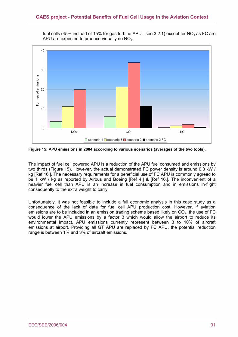
GAES project - Potential Benefits of Fuel Cell Usage in the Aviation Context
EEC/SEE/2006/004 31
fuel cells (45% instead of 15% for gas turbine APU - see 3.2.1) except for NOx as FC are APU are expected to produce virtually no NOx.
0
10
20
30
40
NOx CO HC
Tonn
es o
f em
issi
ons
scenario 1 scenario 3 scenario 2 scenario 2 FC
Figure 15: APU emissions in 2004 according to various scenarios (averages of the two tools).
The impact of fuel cell powered APU is a reduction of the APU fuel consumed and emissions by two thirds (Figure 15). However, the actual demonstrated FC power density is around 0.3 kW / kg [Ref 16.]. The necessary requirements for a beneficial use of FC APU is commonly agreed to be 1 kW / kg as reported by Airbus and Boeing [Ref 4.] & [Ref 16.]. The inconvenient of a heavier fuel cell than APU is an increase in fuel consumption and in emissions in-flight consequently to the extra weight to carry. Unfortunately, it was not feasible to include a full economic analysis in this case study as a consequence of the lack of data for fuel cell APU production cost. However, if aviation emissions are to be included in an emission trading scheme based likely on CO2, the use of FC would lower the APU emissions by a factor 3 which would allow the airport to reduce its environmental impact. APU emissions currently represent between 3 to 10% of aircraft emissions at airport. Providing all GT APU are replaced by FC APU, the potential reduction range is between 1% and 3% of aircraft emissions.
GAES project - Potential Benefits of Fuel Cell Usage in the Aviation Context
32 EEC/SEE/2006/004
CONCLUSION
The objective of this report was to evaluate the use of fuel cells in the airport context. From an extensive literature review it appeared that the use of fuel cell has been largely demonstrated for mobile applications and stationary power sources. The principal advantage of such system is that they emit no NOx, produce only low noise and are more efficient in terms of fuel consumption than traditional engines. There are numerous types of fuel cells, some running on pure hydrogen while other can allow for so called "dirty fuels", i.e. conventional gasoline or kerosene. The run of a fuel cell on hydrogen will produce no emission; the only by-products being heat and water. In other cases, the emission levels are very low for all pollutants of interest for LAQ studies even when the full life cycle of hydrogen production and distribution is considered. The drawbacks of pure hydrogen vehicles are inherent to the need for hydrogen. At the moment there is no H2 production process that is viable from the economical and environmental point of view. There are also technical and cost issues linked to the implementation of a hydrogen distribution system. The disadvantages of "dirty fuel" fuel cells is that the fuel cell need reformer (for carbon and sulphur mainly) which need further R&D costs, and also volume/weight issues as they need to be located on-board the vehicle. However the use of reformer on-board vehicles would eliminate the issues linked with hydrogen storage and production. When considering aviation, and more specifically fuel cell APU, an arising issue is the weight of such a system. Considering an airport, the use of fuel cells would be possible in many domains: virtually any vehicle running on electricity could be fuelled by a fuel cell. GSE as well as personal cars, van / pick ups, buses and trucks could be run by fuel cells. A hydrogen project in Munich airport proved that the use of a hydrogen forklift was economically and technically viable. Additionally any power / heating stationary source on the airport could be operated with fuel cells. The impact of using fuel cell APU on board aircraft has been analysed through a real airport case study. The fuel cells that would be convenient for such duty are SOFC mainly. Two main aircraft manufacturers, Airbus and Boeing, are in the process of developing prototypes of such APU which run with kerosene. The use of fuel cell APU would reduce the fuel consumption of APU by two thirds. The fuel savings could thus reach 1 480 tons for the most probable situation at the case study airport (i.e. for 50 000 jet aircraft movements). The savings per LTO cycle would be around 23 US $ (for jet fuel average price 2004) up to 33 US $ (jet fuel price average for 2005). On a daily basis, the reduction in NOx due to the replacement of GT APU by FC APU is equivalent in the best case to the NOx emissions of 61 heavy truck trips of 100 kilometres. However, fuel cell power density needs to rise from 0.3 kW/kg to 1 kW/kg (as reported by Boeing and Airbus) so that the use of FC APU is acceptable. A low power density directly causes higher fuel consumption and emissions during the in-flight phase of the aircraft trip. In conclusion, despite all the environmental benefits that would be brought by fuel cells, the slow maturation of the hydrogen / fuel cell technology is a severe limitation. It is not expected that fuel cells will be largely used in the near future unless some unexpected technological evolution occur. However, in the case where fuel cell vehicles become widely used, airport could take great advantages in terms of local air quality from implementing fuel cell based GSE fleet and stationary sources.
GAES project - Potential Benefits of Fuel Cell Usage in the Aviation Context
EEC/SEE/2006/004 33
5 REFERENCES
[Ref 1.] EG & G Services Parsons, Inc., 2000, Fuel Cell Handbook (Fifth Edition), for the US Department Of Energy, Morgantown, West Virginia
[Ref 2.] Energy Services, 2004, Fuel Cell Fact Sheet, online on WAPA website www.wapa.gov/es
[Ref 3.] Aicher, T. et al., 2005, Fuel Processors for fuel cell APU applications, Journal of Power Sources, Issue 2005/10/26
[Ref 4.] Hiebel, V., 2005, AIRBUS Fuel Cell System Approach, presented at the European Strategic Research Agenda, Brussels 17-18th March 2005
[Ref 5.] EEC, 2004, Zurich Airport Emission Inventory Using Three Methodologies, EUROCONTROL, online 2005/12/06 at http://www.eurocontrol.int/eec/gallery/ content/public/documents/EEC_SEE_reports/EEC_SEE_2004_010.pdf
[Ref 6.] EEC, 2005, Bucharest H. Coanda Airport Case Study - Phase 1: Emission Inventory, EUROCONTROL internal document
[Ref 7.] NESCAUM, 2001, Airport GSE Survey and Emission Modelling, presented at the Airports Workshop Ozone Transport Commission, BWI Airport 5th December 2001
[Ref 8.] AEAT, 2001, Air Quality at UK Regional Airports in 2005 and 2010, AEA Technology for UK Department for Environment, Transport and the Regions (DETR)
[Ref 9.] Morris, G., 2003, Boeing to test fuel cell APU, Flight International, online at http://www.flightinternational.com/Articles/2003/08/12/Navigation/177/169978/Boeing+to+test+fuel+cell+APU+on+737.html
[Ref 10.] Unique, 2005, Aircraft APU Emissions at Zurich Airport, online on AERONET website at www.aero-net.org/pdf-docs/APU-EmisMeth_050126.pdf
[Ref 11.] FAA, 1997, Air Quality Procedures for Civilian Airports and Air Force Bases, Federal Aviation Administration, Washington DC
[Ref 12.] Unique, 2004, Aircraft Ground Handling Emissions at Zurich Airport - Methodology and Emission Factors, online on AERONET website at www.aero-net.org/pdf-docs/GSE-EmisMeth_040902.pdf
[Ref 13.] Sehra, A. K. et al., 2004, Propulsion and power for the 21st century aviation, Progress in Aerospace Sciences, Issue 40, pp 199-235
[Ref 14.] Brown, F.L., 2001, A comparative study of fuels for on-board hydrogen production for fuel-cell-powered automobiles, International Journal of Hydrogen Energy, Issue 26, pp. 381-397
[Ref 15.] Cacciola, G. et al., 2001, Technology up date and new strategies on fuel cells, Journal of Power Sources, Issue 100, pp 67 -79
GAES project - Potential Benefits of Fuel Cell Usage in the Aviation Context
34 EEC/SEE/2006/004
[Ref 16.] BOEING, 2003, Commercial Airplanes - Fuel Cell APU Overview, presented 15th April 2003 at SECA Annual Meeting, Seattle
[Ref 17.] Adamson, 2005, K.A., Fuel Cell Planes, online on Fuel Cell Today website at www.fuelcelltoday.com
[Ref 18.] Spenser,J., 2004, Fuel Cells in the Air, for Boeing, online on Boeing website at www.boeing.com/news/frontiers/archive/2004/july/ts_sf7a.html
[Ref 19.] Liang, A., 2003, Emerging Fuel Cell Developments at NASA for Aircraft Applications, NASA Glenn Research Center, online at www.netl.doe.gov/publications/proceedings/03/seca/Anita%20Liang.pdf
[Ref 20.] Airbus Deutschland, 2003, Liquid Hydrogen Fuelled Aircraft - CRYOPLANE, European Commission project GRD1-1999-10014
[Ref 21.] Malik, T., 2003, Fuel Cells: Power Plants for Aircraft, online at www.space.com/businesstechnology/technology/aircraft_fuelcells_030709.html
[Ref 22.] Transport Canada, 2002, Aviation Operational Measures for Fuel and Emission Reduction Workshop, Ottawa 5-6 November 2002
[Ref 23.] Dunn, J., 2004, E-plane Fuel Cell Electric Aircraft: A New Era of Aviation, online at www.aviationtomorrow.com
[Ref 24.] Cropper, M., 2004, Opening door to fuel cell commercialisation - Fuel Cell Market Survey: Niche Transport, online on Fuel Cell Today website www.fuelcelltoday.com
[Ref 25.] Breakthrough Technologies Institute, 2004, Fuel Cell Vehicle World Survey, Washington DC, online at http://www.eere.energy.gov
[Ref 26.] http://menegaldo.free.fr/sciencinfuze/fc/docs.htm
[Ref 27.] Contandini, J.F., 2001, Social cost comparison among fuel cell vehicles alternatives, special reports, online at www.methanol.org/fuel-cell
[Ref 28.] AEAT, 2004, Non-Road Mobile Machinery Usage, Life and Correction Factors, AEAT Report for the Department of Transport, online at http://www.airquality.co.uk/archive/reports/cat15/0502141215_NRMM_report_Final_November_2004_3.pdf
[Ref 29.] 2004, Hydrogen Project at Munich Airport, online at http://www.ieahia.org/pdfs/munich_airport.pdf
[Ref 30.] Rachlin, A.S., 2004, LAX Airport Hydrogen Fuelling Stations, State Energy Programs Special Report, online at http://www.eere.energy.gov/hydrogenandfuelcells/pdfs/review04/tv_14_rachlin.pdf
[Ref 31.] Benthem, A.A., et al., 2005, An options approach to investment in a hydrogen infrastructure, Energy Policy, article in press
GAES project - Potential Benefits of Fuel Cell Usage in the Aviation Context
EEC/SEE/2006/004 35
[Ref 32.] Barreto, L. et al., 2003, The Hydrogen economy in the 21st century: a sustainable development scenario, International Journal of Hydrogen Energy, Issue 28, pp. 267-284
[Ref 33.] Lokurlu, A., et al, 2003, Fuel cells for mobile and stationary applications - cost analysis for combined heat and power stations on the basis of fuel cells, International Journal of Hydrogen Energy, Issue 28, pp. 703-711
[Ref 34.] Azar, C., et al., 2003, Global energy scenarios meeting stringent CO2 constraints - cost effective fuel choices in the transportation sector, Energy Policy, Issue 31 pp. 961-976
[Ref 35.] Penner, S.S., 2006, Steps toward an hydrogen economy, Energy, Issue 31, pp. 33-43
[Ref 36.] EUROCONTROL, 2005, ALAQS Concept Document, Internal Document
[Ref 37.] AIP, 2003, Warszawa / Okecie Aerodrome Chart ICA, Air Polska, AD2 EPWA 1-1-1, 17 April 2003, online on AIP website http://www.ead.eurocontrol.int, 2005/11/18
[Ref 38.] Internal communication with Chris Eyers, QinetiQ, 12/08/2006, unpublished.
[Ref 39.] EUROCONTROL Standard Conversion Factors, online on EUROCONTROL website www.eurocontrol.int.
[Ref 40.] Airline Business, May 2005, ISSN 0268-7615.
[Ref 41.] Airline Business, Mars 2006, ISSN 0268-7615.
[Ref 42.] AIRPARIF website, online 22 March 2006 at: http://www.airparif.asso.fr/emissions/chifcle.php?article=chifcle&rubrique=emissions
[Ref 43.] FAA, 2004, Emissions and Dispersion Modelling System, prepared by CSSI, Inc., Washington, DC
[Ref 44.] Janicke Consulting, 2004, LASPORT v1.5 Reference Book, provided with the LASPORT package, information from www.janicke.de


(This page intentionally blank)

For more information about the EEC Society, Environment and Economy Research Area please contact: Ted Elliff SEE Research Area Manager, EUROCONTROL Experimental Centre BP15, Centre de Bois des Bordes 91222 BRETIGNY SUR ORGE CEDEX France Tel: +33 1 69 88 73 36 Fax: +33 1 69 88 72 11 E-Mail: [email protected] or visit : http://www.eurocontrol.int/