g951e1_2 student binder
TRANSCRIPT

28.10.2009
1
© BU LV Motors & BU Machines October 28, 2009 | Slide 1
G951e1_2Basics of electrical motors and the standards / Start here menu
BU LV Motors and BU Machines training
Welcome to the G951e Technical Introduction to Motors and Generators course program!
This is an e-learning course, you can study alone wherever and whenever your want. Please be active and ask questions, we will assist you. You can send your questions to [email protected] or [email protected]. If you need help in navigating in this course, please click the Help button in the top right-hand corner. To view the presenter notes as text, click the Notes button in the bottom of the page. To print the material, click the Attachments button in the tool bar.

28.10.2009
2
© BU Machines & BU LV Motors October 28, 2009 | Slide 2
For new sales person in BUMachines & BU LV MotorsIntroduction to:
basic electrical and mechanicalstructure of our motorstechnical details of differentmotor and generator types
Courses included in the G951e_ course program:
Basics and standardsDC MotorsLow Voltage MotorsServomotorsWind Turbine GeneratorsHigh Voltage Induction MotorsEx MotorsSynchronous Motors
Introduction to G951e_ Course program
Please look up a terminology in
TermBank
This course program has been developed as an introduction to our products for new sales person in BU Machines and BU Low Voltage Motors. It leads you to the basic electrical and mechanical structure of our motors and explains the technical details of the different types of motors and generators.
Course program G951e, together with course G949e, replaces the earlier course G950e. This course program gives an introduction to the basics of motor technology, and the mechanical and electrical structures of the different products: both low and high voltage induction motors and generators; synchronous motors and generators; DC motors; Motors for Hazardous Areas; Servomotors and Wind Turbine Generators.
Course G949e introduces the company and its organizations, the business environment, product range, production and processes, and so on.
During your study, you can look up a terminology through the Termbank linked in ABB Intranet.

28.10.2009
3
© BU Machines & BU LV Motors October 28, 2009 | Slide 3
Reference materials to Motors:
http://inside.abb.com/product/us/9AAC133417.aspx
www.abb.com/motors&generators
Motor Guide
Low voltage Process performance motors
Low voltage Industrial performance motors
Low voltage General performance motors
High voltage induction motors technical catalogue
High voltage induction motors for Chemical, Oil andGas EN 02-2008
Motors for Hazardous Areas EN 01-2008
DMI Catalogue
Introduction to Motors and Generators
During the course you will need to refer to ABB’s internal or external web sites. We also recommend that you use the catalogues during the course. All rights reserved. No part of this document may be reproduced or copied without permission of ABB, ABB Motors and Generators

28.10.2009
4
© BU Machines & BU LV Motors October 28, 2009 | Slide 4
For information on our training events, see:
BU LV Motors:http://inside.abb.com/product/ap/seitp322/2d778c69e0d4a7b5c125707d00374716.aspx
BU Machines:http://fi.inside.abb.com/product/ap/seitp322/2e4e359d14eb2f63c125751900464529.aspx
G951e_ Technical Introduction to Motors and Generatorscourse program, produced for ABB, BU Machines & BU LVMotors, 2008. Second Edition (v.1.2).
Contact information:
Introduction to Motors and Generators
BU LV Motors TrainingP.O.Box 633, FIN-65101 Vaasa,FinlandTel. +358-50 33 44350Fax. +358-10 22 47372e-mail:[email protected]
BU Machines TrainingP.O.Box 186, FIN-00381 Helsinki,FinlandTel. +358-50 33 22328Fax. +358-10 22 22141e-mail:[email protected]
For information on our training events, visit us at motors and generators training web site.
The course program “G951e Technical Introduction to Motors and Generators” has been produced for ABB Business Units Motors and Generators in 2006. This is the third edition, version 1.3, copyright 2009 by ABB, BU Machines and BU Low Voltage Motors.

28.10.2009
5
© BU Machines & BU LV Motors October 28, 2009 | Slide 5
Course duration
Equivalent to 3 days classroom training
To pass the G951e_ course program, start with G951e1_2 Basics of electrical motors and standards + another course included in the program
Study the G951e_ course program according to your individual plan
Course type
web-based course in English
Prerequisites
basic knowledge of electronics
experience of using PCs with the Windows environment
Description of G951e_ course program
The duration of this course program depends on the participant. The whole program is equivalent to three days of classroom training. To pass the G951e_ course program, at least two of the included courses have to be studied. There are in total eight courses dealing with the different products produced by BU Machines and BU LV Motors. Start your studies by taking this first, mandatory course “G951e1_2 Basics of electrical motors and standards”. You are recommended to select the courses you deal with in your job area. The course program has been scheduled to be studied according to your individual plan, usually within five or six weeks. There is a final exam at the end of each course. To pass the exam, 50% of the questions have to be answered correctly.
The goal of this course program is to introduce the basics of electrical motors and the technical features of ABB motors and generators. The training is targeted to all new people in ABB's motor and generator business.
A basic knowledge of electronics and experience of using PCs with the Windows environment is recommended. It is assumed that you are new to e-learning software and methods.

28.10.2009
6
© BU Machines & BU LV Motors October 28, 2009 | Slide 6
The complete G951e_Technical Introduction coursepackage includes 8 separate courses: G951e1_2 ... G951e9.After completing the G951e1_2 course you will know:
the basic function of a motor and the basic electricalfeatures of an ABB motorthe different electrical and mechanical requirements ofthe commonly used standards
After completing the other courses included in the course program (G951e3 to G951e9) you will know:
DC MotorsHigh voltage induction motorsLow voltage motorsMotors and generators for hazardous areasServomotorsSynchronous Motors and GeneratorsWind Turbine Generators
Course description
The complete G951e_Technical Introduction course package includes 8 separate courses: from G951e1_2 to G951e9.
After you have completed the whole course package, you will be able to describe the basic function of a motor and the basic electrical features of an ABB motor. You will be able to recognize the different electrical and mechanical requirements of the commonly used standards (IEC, NEMA), and to describe the main features of the following motors and generators manufactured by ABB: DC Motors, High voltage Induction Motors; Low voltage motors, Ex motors, Servomotors, Synchronous motors and generators and Wind turbine generators.

28.10.2009
7
28.10.2009
8
© BU LV Motors & BU Machines October 28, 2009 | Slide 8
G951e1 Basics of electrical motors and generators

28.10.2009
9
© BU Machines & BU LV Motors October 28, 2009 | Slide 9
After completing this course module you will understand:
the basics of the electrical motor
the structure and demands of a motor
the physical background of the induction motor
the electrical structure of ABB's low and high voltage induction motors and generators
Objectives
After successfully completing this course module you will be able to describe the basics of the electrical motors and understand the structure and demands of a motor.
This module will also explain the physical background of the induction motor and the electrical structure of ABB's low and high voltage induction motors and generators, including the electrical motor components, torque and speed, power factor, efficiency, rating plate, winding, and insulation.

28.10.2009
10
© BU Machines & BU LV Motors October 28, 2009 | Slide 10
Electrical motor
More than half of the electrical energy produced is used by electrical motors
Electrical motors are used worldwide in many industrial, utility, commercial, or residential applications
Electricity is an important source of energy in our society. More than half of the electrical energy produced is used by electrical motors. Electrical motors are used worldwide in many industrial, utility, commercial, or residential applications.

28.10.2009
11
© BU Machines & BU LV Motors October 28, 2009 | Slide 11
Principles of action of electrical motors and generators
Used to convert mechanical power into electrical energy or vice versa
All rely on electromagnetic induction
Rotating electrical machines are used to convert mechanical power into electrical energy or vice versa. All electrical machines, whether motors or generators using direct or alternating current, rely on the principles of electromagnetic induction for their action.

28.10.2009
12
© BU Machines & BU LV Motors October 28, 2009 | Slide 12
Principles of action of electrical motors and generators
A conductor moving across a magnetic field creates an electromotive force (emf)
Resulting current flow and magnetic field around the conductor tend to oppose the motion that is producing the emf
A conductor moving across a magnetic field becomes the seat of an electromotive force (emf). The direction of the emf is in the right angle to both the direction of the motion and the direction of the magnetic field.
The amount of "induced“ voltage depends upon the length of the conductor actually in the field, the speed of the relative motion between the conductor and the magnetic field, and the strength of the magnetic field.
Because of the direction or polarity of the induced emf, the resulting current flow and the magnetic field around the conductor produced by it tend to oppose the motion that is producing the emf. The principle of this action can be presented in best for instance, an elementary generator consisting of a loop of wire that is mechanically rotated within a magnetic field.

28.10.2009
13
© BU Machines & BU LV Motors October 28, 2009 | Slide 13
Principles of action of electrical motors and generators
single-phase machinedelta connection
In the illustration, A will always be moving in the opposite direction of B, relative to the magnetic field, and hence emf induced in A will be in the opposite direction to that of B. These two emfs, therefore, add up when the coil sides are connected as shown. When the coil side A is in position 1, it will be moving parallel to the direction of the magnetic field. There is no relative motion across the field and no emf is induced. When the coil has rotated 90° to position 2, it will be moving at right angles to the field and an emf is induced towards the observer’s direction, as shown by the arrows. Slip ring R1 will, therefore, appear to have positive polarity with regard to R2. After a further 90° rotation, coil side A will again be moving parallel to the direction of the field and no emf will be induced. After a 270° rotation, in position 4, the coil side will again be moving at right angles to the field and an emf will be induced in the opposite direction to that of position 2 since the direction of movement is now reversed. Slip ring R1 will now appear to have negative polarity with regard to R2. This elementary generator produces an emf that is alternating in direction with a complete cycle of positive and negative changes taking place once per revolution. Since it is relative motion between conductor and field, which includes the emf, it matters little whether the conductor is moving in a stationary field system or whether the field system is moving within stationary conductors. The alternator described in this example is known as a single-phase machine because there is only one circuit where the emf is induced. It is possible to install 3 separate groups. Now the stator has three separate groups of coils spaced 120 electrical degrees apart round the stator core. The voltages in each of these "phases" reach maximum values at different times as the magnetic field passes them in succession. The voltage, which appears between any of the 3 machine terminals, is that of two-phase windings in series. Since these are 120° out of phase, the terminal voltage is 1.73 times that of the voltage of one phase. Alternatively, the end of one coil group can be connected to the start of another to form a closed loop, the joints forming the terminal connections. This is known as the delta connection. The terminal voltage is the same as that of each phase and the line current is shared between the phase windings.
28.10.2009
14
© BU Machines & BU LV Motors October 28, 2009 | Slide 14
Principles of action of electrical motors and generators
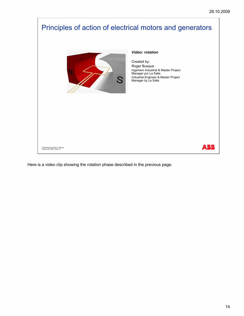
Video: rotation
Created by:Roger BusqueIngeniero Industrial & Master ProjectManager por La Salle.Industrial Engineer & Master ProjectManager by La Salle
Here is a video clip showing the rotation phase described in the previous page.
28.10.2009
15
© BU Machines & BU LV Motors October 28, 2009 | Slide 15
Principles of action of electrical motors and generators
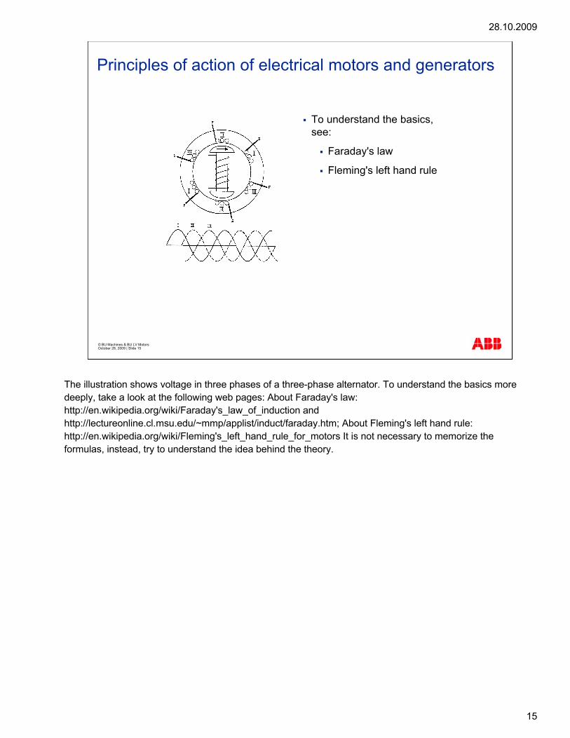
To understand the basics, see:
Faraday's law
Fleming's left hand rule
The illustration shows voltage in three phases of a three-phase alternator. To understand the basics more deeply, take a look at the following web pages: About Faraday's law: http://en.wikipedia.org/wiki/Faraday's_law_of_induction and http://lectureonline.cl.msu.edu/~mmp/applist/induct/faraday.htm; About Fleming's left hand rule: http://en.wikipedia.org/wiki/Fleming's_left_hand_rule_for_motors It is not necessary to memorize the formulas, instead, try to understand the idea behind the theory.

28.10.2009
16
© BU Machines & BU LV Motors October 28, 2009 | Slide 16
Electrical motor componentsActive parts of an HV motor
Stator
Bearing
Bearing
Rotor
Here a high voltage motor/generator is illustrated. The basic construction of the AC induction motor is simple and has changed very little over the years. Next, we will discuss the basic components of a motor. The stator windings are insulated copper wire, which are inserted into slots in the stator laminations. These slots have insulation between the windings and the steel laminations. This is called the "stator core". The different winding designs provide different output and speed combinations. The stator core is inserted into the stator frame. The ends of the winding are brought out through the motor casing to the terminal board in a terminal box mounted on the frame. This is where the mains leads are connected. The rotor consists of laminations, the shaft, and the rotor winding or bars. The type of winding will depend on the type of motor required. If the rotor has a winding similar to that of the stator, it is known as a "wound rotor motor" (also known as a slip-ring motor). If the "winding" consists of solid bars that are joined at either end by a short-circuit ring, it is known as a "squirrel cage" motor. This is because the cage of the rotor resembles the cage that squirrels play with when in captivity. The bars are generally aluminum, but can be copper or any such material. Aluminum is commonly used for LV induction motors and copper for HV motors and generators. The squirrel cage rotor motor is the most common type in use today as it requires simple control gear and, in most cases, can be used instead of a wound rotor motor. The stator core and rotor core constitute the active part of a motor. The bearings are used to support the shaft and to enable it to rotate.

28.10.2009
17
© BU Machines & BU LV Motors October 28, 2009 | Slide 17
Electrical motor componentsActive parts of an HV motor
Video: the stator and rotor packet
Created by:Roger Busque
Here is a video clip showing the stator packet and rotor packet, which constitute the active part of a motor.
28.10.2009
18
© BU Machines & BU LV Motors October 28, 2009 | Slide 18
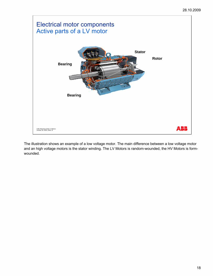
Electrical motor componentsActive parts of a LV motor
Rotor
Stator
Bearing
Bearing
The illustration shows an example of a low voltage motor. The main difference between a low voltage motor and an high voltage motors is the stator winding. The LV Motors is random-wounded, the HV Motors is form-wounded.

28.10.2009
19
© BU Machines & BU LV Motors October 28, 2009 | Slide 19
Electrical motor componentsActive parts of a LV motor
Video: rotorCreated by:Roger Busque
The rotor consists of laminations, the shaft, and the rotor winding or bars.

28.10.2009
20
© BU Machines & BU LV Motors October 28, 2009 | Slide 20
Voltage of an LV/HV motor and generator
Low voltage 0 < U ≤ 1 kV
Medium voltage 1 < U ≤ 6.6 kV
High voltage 6.6 < U ≤ 11.5 kV
Generator:
Low Voltage: 0 – 1kVMedium Voltage: 1kV – 15 kV
Motors:
Internally, sometimes the terms 'medium voltage' and 'high voltage' motors/generators can be used. It is good to know the difference between them.

28.10.2009
21
© BU Machines & BU LV Motors October 28, 2009 | Slide 21
Components of an HV motor/generator
The illustration shows an explosion view of a high voltage motor/generator (AMA).

28.10.2009
22
© BU Machines & BU LV Motors October 28, 2009 | Slide 22
Components of a LV motor
Fan cover
Fan
N-end
Rotor
Stator core &stator winding
Shaft
Bearing
Terminal box lid
Bearing
Frame
D-end
Terminal block
Terminal box
The illustration shows the main components of a low voltage motor. The active parts of the motor are: rotor, stator core, and stator winding.
28.10.2009
23
© BU Machines & BU LV Motors October 28, 2009 | Slide 23
Magnetism
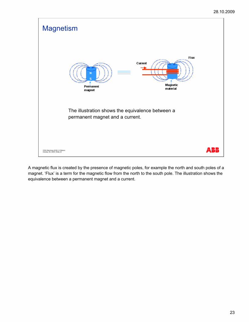
The illustration shows the equivalence between a permanent magnet and a current.
A magnetic flux is created by the presence of magnetic poles, for example the north and south poles of a magnet. ‘Flux’ is a term for the magnetic flow from the north to the south pole. The illustration shows the equivalence between a permanent magnet and a current.

28.10.2009
24
© BU Machines & BU LV Motors October 28, 2009 | Slide 24
Magnetism
Video: Magnetic flux 1Created by:Roger Busque
Video: Magnetic flux 2Created by:Roger Busque
Video clips of Magnetic flux 1 and 2.
28.10.2009
25
© BU Machines & BU LV Motors October 28, 2009 | Slide 25
Magnetic field in a motor
FLUX
Stator core
Stator winding
Rotorpacket
Rotorbar
Air gap betweenstator and rotor
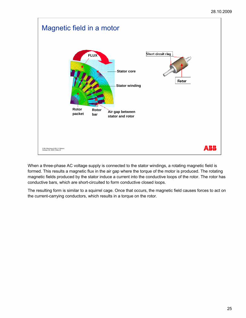
When a three-phase AC voltage supply is connected to the stator windings, a rotating magnetic field is formed. This results a magnetic flux in the air gap where the torque of the motor is produced. The rotating magnetic fields produced by the stator induce a current into the conductive loops of the rotor. The rotor has conductive bars, which are short-circuited to form conductive closed loops.
The resulting form is similar to a squirrel cage. Once that occurs, the magnetic field causes forces to act on the current-carrying conductors, which results in a torque on the rotor.

28.10.2009
26
© BU Machines & BU LV Motors October 28, 2009 | Slide 26
Pole number
The pole number is the number of magnetizing poles generated by the stator winding
The pole number is the number of magnetizing poles generated by the stator winding. Poles exist in pairs, north and south poles, by the direction of the magnetic field, so the pole number is always an even number. One north pole (N) and one south pole (S) form one pole pair (p), and they follow each other.
Stator winding produces a rotating magnetic field when supplied with a three-phase AC system.

28.10.2009
27
© BU Machines & BU LV Motors October 28, 2009 | Slide 27
Magnetic field in a motor
The speed of the magnetic field rotating under a certain supply frequency depends on the pole number of the winding. Windings with different pole numbers differ from each other with regard to coil shape and location in the stator slots. Rotational speed of the magnetic field dependent on the winding pole number at 50 Hz supply frequency in the following way: 2-pole (2p=2) winding produces 3,000 rpm speed; 4-pole (2p=4) winding produces 1,500 rpm speed; 6-pole (2p=6) winding produces 1,000 rpm speed; and 8-pole (2p=8) winding produces 750 rpm speed. At 60 Hz supply frequency the speed values are 20 % higher. The abbreviation p stands for “pole pair number” and the abbreviation 2p means “pole number”.

28.10.2009
28
© BU Machines & BU LV Motors October 28, 2009 | Slide 28
Windings
Windings designed for a specific voltage and frequency
Slot windings used as
stator windings
rotor windings in the induction motors/generators
The windings are designed for a given voltage and frequency. Slot windings are used as stator windings and also as rotor windings in the induction motors/generators.
28.10.2009
29
© BU Machines & BU LV Motors October 28, 2009 | Slide 29
Stator winding
Random winding
Form wound winding
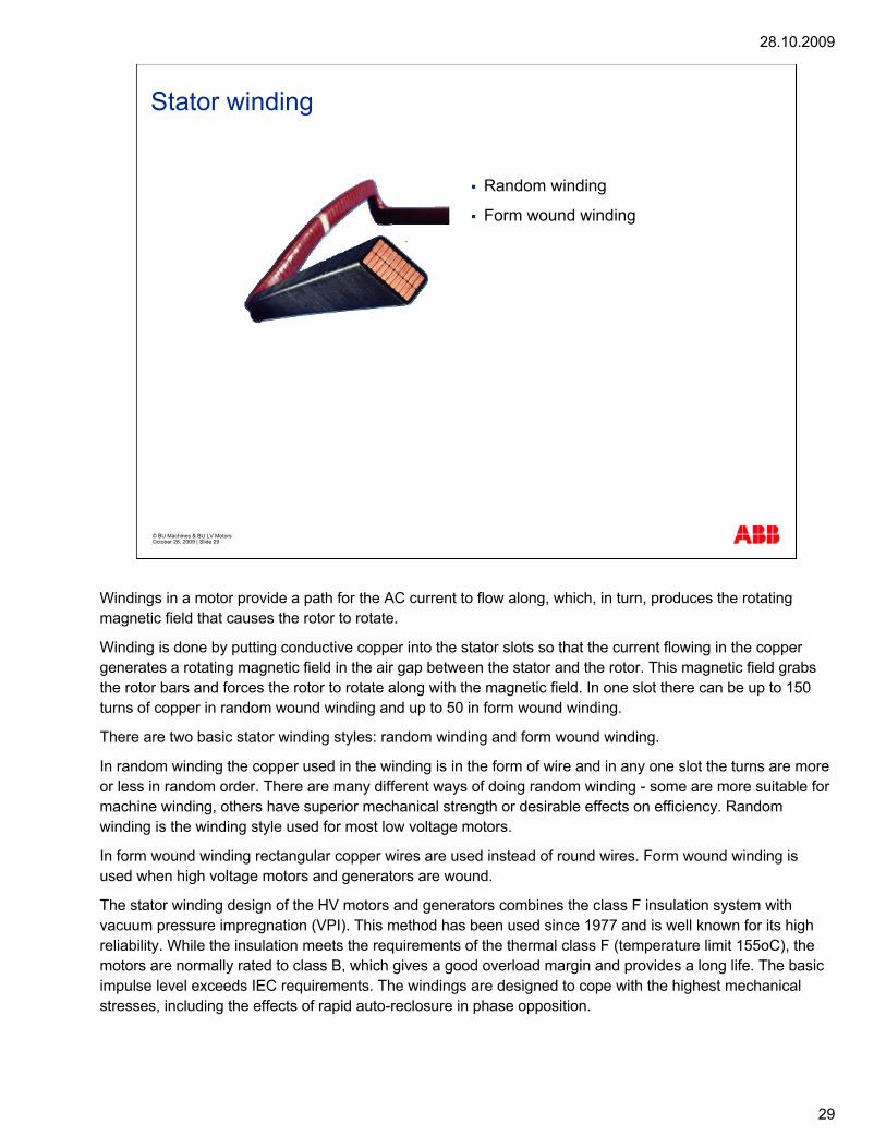
Windings in a motor provide a path for the AC current to flow along, which, in turn, produces the rotating magnetic field that causes the rotor to rotate.
Winding is done by putting conductive copper into the stator slots so that the current flowing in the copper generates a rotating magnetic field in the air gap between the stator and the rotor. This magnetic field grabs the rotor bars and forces the rotor to rotate along with the magnetic field. In one slot there can be up to 150 turns of copper in random wound winding and up to 50 in form wound winding.
There are two basic stator winding styles: random winding and form wound winding.
In random winding the copper used in the winding is in the form of wire and in any one slot the turns are more or less in random order. There are many different ways of doing random winding - some are more suitable for machine winding, others have superior mechanical strength or desirable effects on efficiency. Random winding is the winding style used for most low voltage motors.
In form wound winding rectangular copper wires are used instead of round wires. Form wound winding is used when high voltage motors and generators are wound.
The stator winding design of the HV motors and generators combines the class F insulation system with vacuum pressure impregnation (VPI). This method has been used since 1977 and is well known for its high reliability. While the insulation meets the requirements of the thermal class F (temperature limit 155oC), the motors are normally rated to class B, which gives a good overload margin and provides a long life. The basic impulse level exceeds IEC requirements. The windings are designed to cope with the highest mechanical stresses, including the effects of rapid auto-reclosure in phase opposition.

28.10.2009
30
© BU Machines & BU LV Motors October 28, 2009 | Slide 30
Poles Winding Diagram
Single layer
2p = 4 poles
Q1 = 72 slots
q1 = 6 slots (for every pole of every phase)
W = 15 teeth (between entrance and exit of one turn)
The diagram is a tool for transferring information between the designer and manufacturing. For different pole numbers there are different winding diagrams to indicate the order of the wires. In a winding diagram every phase is marked with a different color.

28.10.2009
31
© BU Machines & BU LV Motors October 28, 2009 | Slide 31
Insulation
Insulation systems are dimensioned according to:
voltage level
Supply voltage type
environmental conditions
Endurance tests when new insulation systems are developed:
electrical aging
thermal aging
mechanical aging
aging due to surrounding conditions
combined aging
Insulation systems are dimensioned according to several factors: voltage level, supply voltage type (DOL = Direct On Line, PWM-converter, cycloconverter), environmental conditions, for example, height of the site above sea level, temperature, and humidity.
Endurance tests are needed when new insulation systems are developed. Typical endurance tests are electrical aging, thermal aging, mechanical aging (for example vibration), aging due to surrounding conditions, and combined aging (for example, thermal and electrical). Aging tests are typically very long lasting, even years. To reduce the time, they are normally done as so-called accelerated tests with higher stresses (for example, voltage and frequency and temperature) than in real operation. The life-times corresponding to the stresses in real operation can be calculated from these results.
When developing insulation systems, the manufacturing point of view also has to be taken into account, in other words, how to manufacture reliably and economically without occupational safety problems.

28.10.2009
32
© BU Machines & BU LV Motors October 28, 2009 | Slide 32
DC motors winding and insulation
Windings designed for a specific voltage
Coils used as stator windings
Slot windings used as rotor windings
The windings are designed for a given voltage. Coils are used as stator windings, and slot windings are used as rotor windings in these motors or generators.

28.10.2009
33
© BU Machines & BU LV Motors October 28, 2009 | Slide 33
DC Motor stator winding
The main tasks of the DC motor stator:
produce a fixed magnetic flux to interact with the armature
house the commutating windings and compensation windings
Main components of the stator:
frame of laminated electroplates
main poles and interpoles of laminated electroplates,
stator windings and commutation windings of varnish-insulated copper wire
compensation windings (not DMI 180-225)
The windings in the motor provide a path for the DC current to flow along, which, in turn, produces the rotating magnetic field that causes the rotor to rotate.
The main task of the DC motor stator is to produce a fixed magnetic flux to interact with the armature. This is done by the excitation winding. The stator also houses the commutating windings and compensation windings, which are auxiliary devices that are used to prevent deformation of the main flux.
A compensation winding is installed on the magnetic poles of the stator to smoothen the field across the pole. Without the compensation winding the left side of the N-pole would get saturated because of the additional magnetic field.
Commutating windings or interpoles are installed between the magnetic poles to straighten the magnetic field.
Because of armature reaction, the magnetic field bends and causes misplacement in the inducted voltage at the armature winding.
The main components of the stator are: frame of laminated electroplates; main poles and interpoles of laminated electroplates; stator windings and commutation windings of varnish-insulated copper wire; and compensation windings (not DMI 180-225).

28.10.2009
34
© BU Machines & BU LV Motors October 28, 2009 | Slide 34
DC 6 Poles winding diagram
The winding diagram indicates the order of the wires, as shown in this diagram for 6 poles.

28.10.2009
35
© BU Machines & BU LV Motors October 28, 2009 | Slide 35
DC Insulation
Insulation system:
moisture-resistant
suitable for use in tropical climates without modification
Armature coils and stator windings have dual insulation coats
Copper wire insulation, the Nomex and the impregnation varnish have a temperature index above class H
The motors comply with the requirements of Class 200 /H insulation. The insulation system is moisture-resistant and is suitable for use in tropical climates without modification. The armature coils and stator windings have dual insulation coats. The base coat is a polyesterimide with a top coat of polyamide-imideenamel. The insulation to earth is of amid fiber (Nomex). All windings are impregnated with varnish, which gives high mechanical strength.
The copper wire insulation, the Nomex and the impregnation varnish have a temperature index well above class H. There is, therefore, a high margin of safety in addition to the high overload capacity.

28.10.2009
36
© BU Machines & BU LV Motors October 28, 2009 | Slide 36

28.10.2009
37
© BU LV Motors & BU Machines October 28, 2009 | Slide 37
G951e1 Torque, speed and formulas

28.10.2009
38
© BU Machines & BU LV Motors October 28, 2009 | Slide 38
Torque and speed of an AC motor
locked-rotor torque
pull-up torque
breakdown torque
An asynchronous motor is a motor whose rotor does not rotate at exactly the same speed as the stator field. The locked-rotor torque is the minimum measured torque the motor develops at its shaft extension with the rotor stationary and the rated voltage and frequency applied. The pull-up torque is the smallest torque the motor develops between zero speed and the speed corresponding to the breakdown torque when the motor is supplied with the rated voltage and frequency. This definition does not apply to induction motors, whose torque continuously decreases with increasing speed. This value applies to the usual mean torque characteristic, which excludes transient effects. The breakdown torque is the maximum torque the motor develops with the rated voltage and frequency applied at the operating temperature and when constantly loaded. This term does not apply to motors whose torque steadily decreases with increasing speed. They do not have definite breakdown torque. If the rotor is mechanically driven by an external machine at a speed that is greater than that of the rotating magnetic field, with the machine connected to the power network and the direction of rotation the same as that of the stator field, the asynchronous machine becomes an asynchronous generator. The asynchronous generator returns the power applied mechanically to its rotor as electric power to the network, in this case over-synchronously because the slip is negative. The rotor currents are reversed and the torque produced opposes the rotation of the machine, that is, it tends to retard it.

28.10.2009
39
© BU Machines & BU LV Motors October 28, 2009 | Slide 39
AC Speed - magnetic field
[ ][ ]
numberpole120f
n HzRPMs
×=
The synchronous speed can be calculated with the formulas
The speed of the rotating field is constant and it rotates at synchronous speed. The synchronous speed is dependent on the frequency and the pole number of the winding. The synchronous speed can be calculated with the formula shown in this slide. The synchronous speed of the motor is determined by the frequency of the supply voltage and the pole number of the motor. f in the formula stands for Electrical frequency in Hz (50Hz or 60 Hz).

28.10.2009
40
© BU Machines & BU LV Motors October 28, 2009 | Slide 40
AC Voltage versus time
An AC Voltage is defined by the value of volts and the frequency. p = Number of pole pairs (=number of poles / 2). The flux is rotated at a speed called "synchronous speed", corresponding to the electrical frequency of the network and to the number of pole pairs. As long as the rotor is rotated at synchronous speed, no current is induced in the rotor bar, and consequently no torque is developed by the motor. Current only exists in the rotor bar if the speed of the rotor (n) is below the synchronous speed (as soon as a load torque is applied to the shaft), which means that the speed of the rotor does not rotate at synchronous speed, and the rotor speed lags behind the speed of the magnetic field. In a case of generating, the speed of the rotor is above the synchronous speed.
28.10.2009
41
© BU Machines & BU LV Motors October 28, 2009 | Slide 41
AC Torque curve
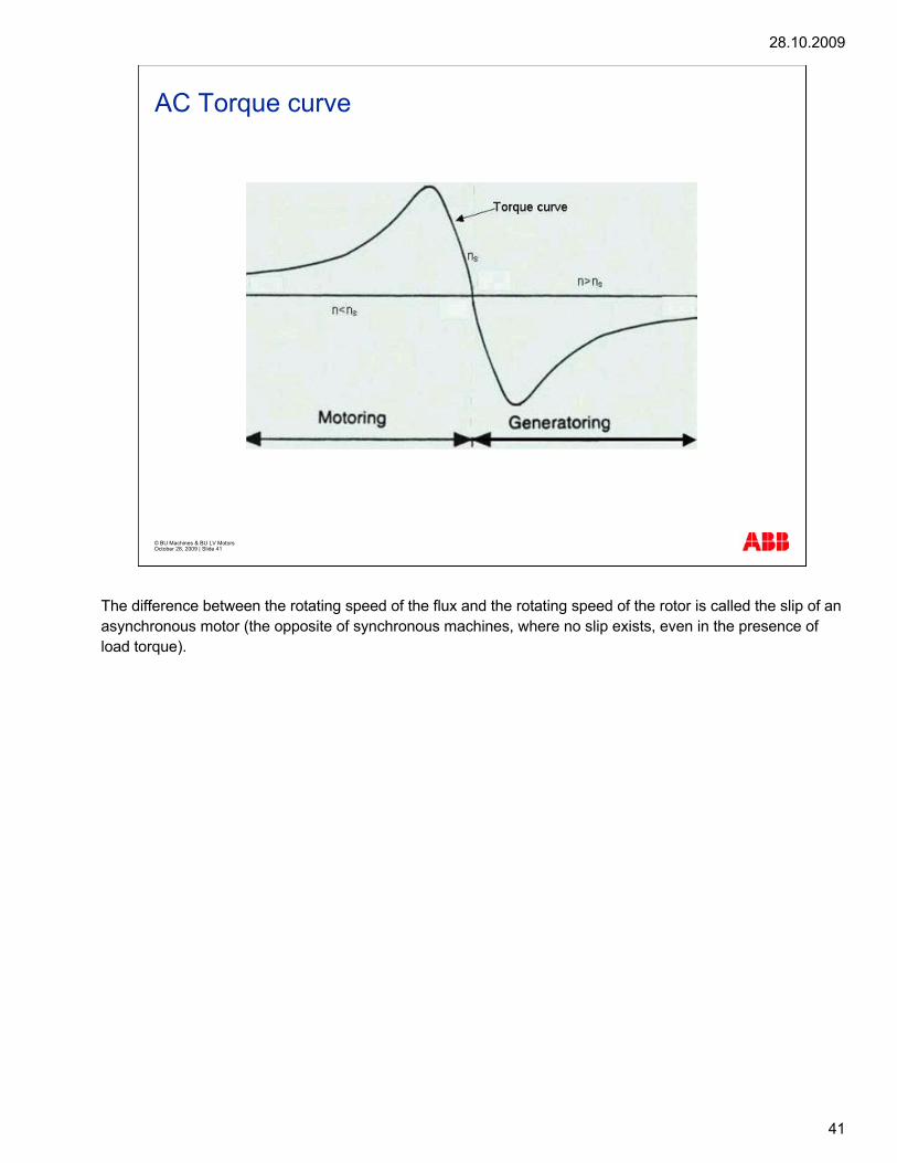
The difference between the rotating speed of the flux and the rotating speed of the rotor is called the slip of an asynchronous motor (the opposite of synchronous machines, where no slip exists, even in the presence of load torque).

28.10.2009
42
© BU Machines & BU LV Motors October 28, 2009 | Slide 42
Slip
The slip can be expressed in either rpm or per unit
n = nominal speed
ns = synchronous speed
[ ] nnSlip sRPM −=
[ ]s
s% n
nnSlip −=
e.g. 1000 rmp – 992rpm
e.g. 1000 rmp – 992rpm1000 rmp
The slip can be expressed in either rpm or per unit, as is shown in the formulas. n stands for nominal speed and ns stands for synchronous speed.

28.10.2009
43
© BU Machines & BU LV Motors October 28, 2009 | Slide 43
Torque v.s. speed for Asynchronous motor
The illustration shows the effect of increased speed on torque for an asynchronous motor. The magnitude of the (mechanical) torque available at the shaft depends on the magnitude of the slip – that is, on the amount the rotor speed lags behind the speed of the rotating magnetic field. The relationship between the torque and the speed of the motor is illustrated by the speed-torque characteristic.
28.10.2009
44
© BU Machines & BU LV Motors October 28, 2009 | Slide 44
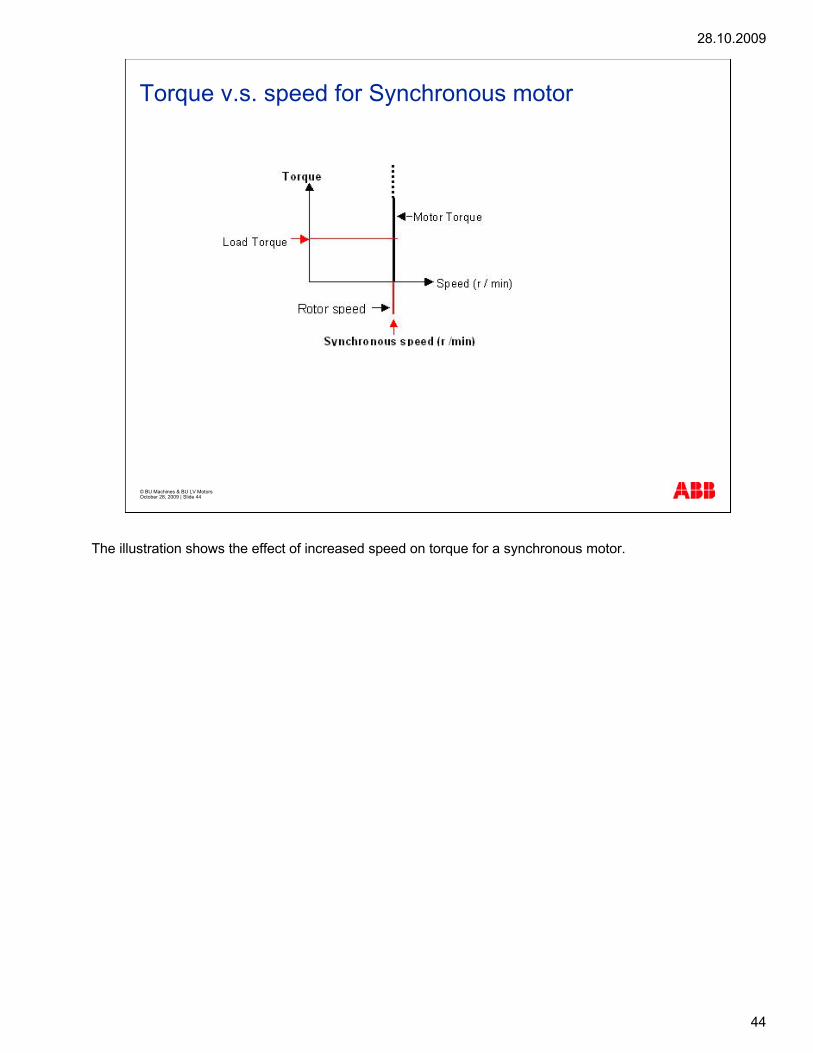
Torque v.s. speed for Synchronous motor
The illustration shows the effect of increased speed on torque for a synchronous motor.
28.10.2009
45
© BU Machines & BU LV Motors October 28, 2009 | Slide 45
Torque
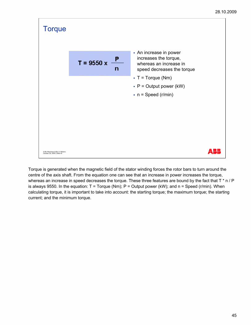
An increase in power increases the torque, whereas an increase in speed decreases the torque
T = Torque (Nm)
P = Output power (kW)
n = Speed (r/min)
Torque is generated when the magnetic field of the stator winding forces the rotor bars to turn around the centre of the axis shaft. From the equation one can see that an increase in power increases the torque, whereas an increase in speed decreases the torque. These three features are bound by the fact that T * n / P is always 9550. In the equation: T = Torque (Nm); P = Output power (kW); and n = Speed (r/min). When calculating torque, it is important to take into account: the starting torque; the maximum torque; the starting current; and the minimum torque.

28.10.2009
46
© BU Machines & BU LV Motors October 28, 2009 | Slide 46
Torque
This graph is typical for an LV motor. It shows the Torque/speed curve. The shape of the torque/speed curve is determined by the slot shapes and slot alignment in the stator and rotor. The level of the Nominal torque is determined by the winding (number of turns). According to IEC, the maximum torque (Tmax) of the motor should always be more than 1.6 times the nominal torque (Tn). At a speed of 0 rpm the motor can give starting torque (Ts). This Ts should be big enough to counter the decelerating masses of the load and rotating rotor body in less than the given maximum permitted starting time.

28.10.2009
47
© BU Machines & BU LV Motors October 28, 2009 | Slide 47
Torque
This graph is typical for an MV or large motor. The minimum torque (Tmin) is not always at 0 rpm, for example a double cage rotor has minimum torque at around 0.7 times the nominal speed. This should be taken into account when dimensioning motors for constant torque applications. At direct-on-line start the torque produced by the motor has to be greater than the load torque (with reasonable gap) at any speed. If the load torque at any speed is greater than the torque created by the motor, the motor will not be able to start or achieve nominal speed.

28.10.2009
48
© BU Machines & BU LV Motors October 28, 2009 | Slide 48
Torque
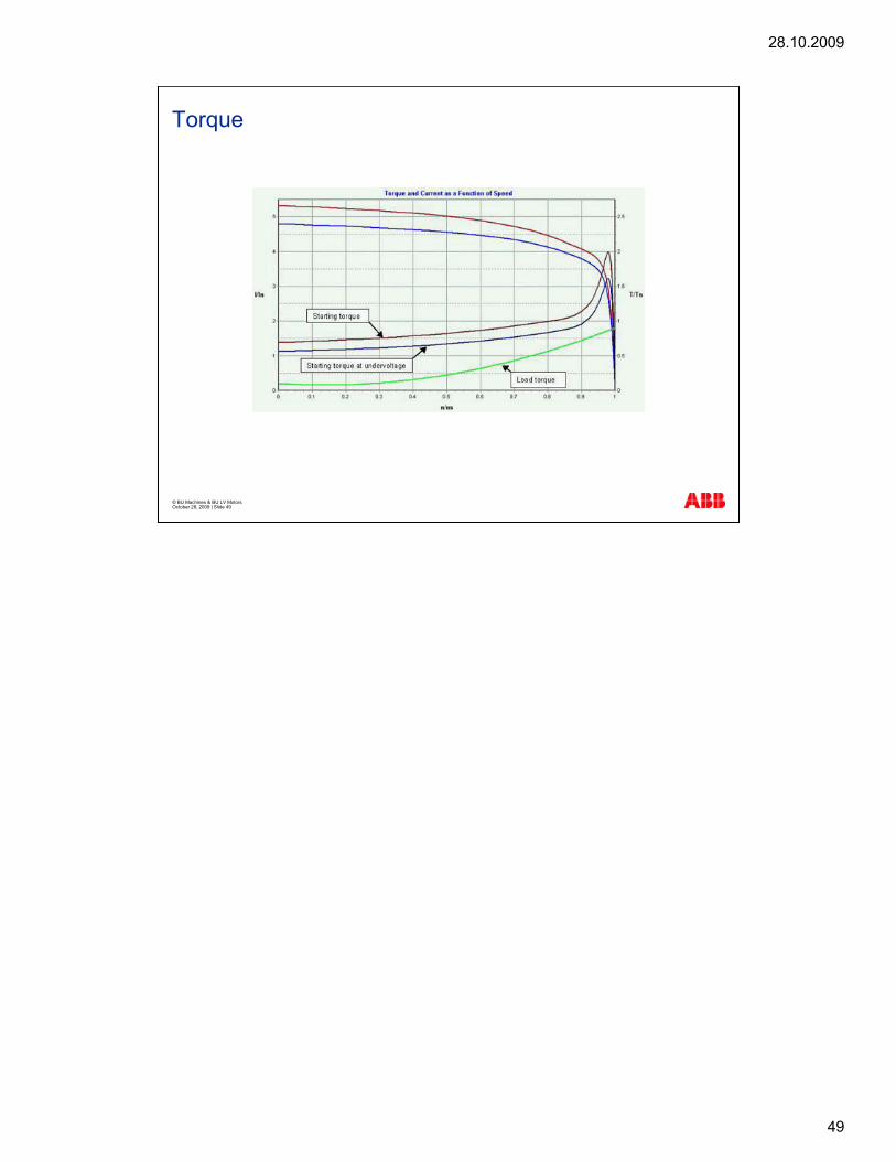
The starting current of large motors may cause voltage dips, especially in weak grids. Therefore, motors have to be able to start with reasonable under voltage.
28.10.2009
49
© BU Machines & BU LV Motors October 28, 2009 | Slide 49
Torque

28.10.2009
50
© BU Machines & BU LV Motors October 28, 2009 | Slide 50
Torque
A high current is generated when an asynchronous motor is switched on. The starting current depends on the motor design; the value is usually between 6.5 and 7.5 times the nominal current and the shape is determined by the same parameters as the torque design.
The illustration shows the "shape" of torque and current versus speed for small motors.

28.10.2009
51
© BU Machines & BU LV Motors October 28, 2009 | Slide 51
Torque
The illustration shows the "shape" of torque and current versus speed for large motors.

28.10.2009
52
© BU Machines & BU LV Motors October 28, 2009 | Slide 52
Formulas
T(Nm) =60 000
2π[ ]x[ ]P(kW)
n
T(Nm) = 9549.30[ ]x[ ]P(kW)
n
P(kW) = T(Nm) x w(rd/s) / 1000
ω(rd/s) = 2pn / 60 (where n is rpm)
P(kW) = T(Nm) x n x 2p / 60 000or
Torque is the rotational equivalent of linear force and, for any rotating machine, if Power and Speed are known, the Torque is given by the formula shown in the blue background. In the formula: T = Torque (Nm), P= Output power (kW), and n= Speed (r/min).
In the formula , 9550 is a constant, which can be calculated with the either of the formulas shown on the right.

28.10.2009
53
© BU Machines & BU LV Motors October 28, 2009 | Slide 53
Operation
DCMotor
IA
If
Ud E
Φ
( )
( )
( )( )φ××−=
×+=φ××=
−=
−==φ
×φ×=
kIRUn.7
IREU.6nkE.5R
EUI.4
TTT.3If.2
IkT.1
Aid
Aid
i
dA
loadoutputAcc
f
Aoutput
(1) The output torque of the motor is proportional to the armature current as long as (2)the excitation is kept constant. (3) if the output torque exceeds the load torque, there is acceleration torque and the speed of the motor starts to increase. (4) the armature current and, accordingly, the output torque can be increased by increasing the voltage supplied by the DC converter. (5) when the armature starts to rotate through the magnetic flux of the stator, a voltage (emf) is induced, the polarity of which is the opposite of the supply voltage. (6) to maintain the current (and torque), the supply voltage has to be increased as the speed and armature emf increase. The speed can be controlled by the supply voltage until the nominal armature voltage has been reached. (7) this normally coincides with reaching the maximum output voltage of the supplying DC converter. The speed range from standstill up to this point is called the basic speed range. To increase the speed above the basic speed range, the armature emf has to be decreased. As we have seen (5), the armature emf depends on excitation as well as speed. The speed can be further increased by decreasing the excitation (7). However, since torque is a direct function of excitation (2), from this point on the available torque decreases in inverse proportion to the speed. This speed range is called the field weakening speed range. For motors without compensation windings the relationship between basic and field weakening speed range is 1:3, and for compensated motors 1:5. The ultimate speed limit of a DC motor is set by mechanical parameters.

28.10.2009
54
© BU Machines & BU LV Motors October 28, 2009 | Slide 54
Controlling torque and speed by excitation
Basic Speed FieldWeakeningSpeed
nb nmax
UN
IN
IN
TN
PN
UA
IA
If
T
P
n
Armature Voltage
Armature Current
Excitation Current
Torque
Power
As is evident from equations 1 and 2, it is also possible to control the magnitude and direction of the torque entirely by varying the field current. Nevertheless, this is rarely done in modern drives, because the excitation winding has a much higher impedance than the armature, which makes torque by this method slower.

28.10.2009
55
© BU Machines & BU LV Motors October 28, 2009 | Slide 55
DMI Motor characteristicsTorque as a function of speed
0
0,2
0,4
0,6
0,8
1
1,2
0 1 2 3 4 5 6
Speed [rpm]
Torq
ue (N
m)
Constant Torque(P=k x n)
Constant Power(P=k)
Commutation limit(P=k/n)
Commutation Limit(compensationwinding)Mechanical Limit
Torque
Basic Field Weakening
This graph demonstrates the relationship between torque and rotational speed (RPM).
Maximum torque is generated when the rotor is stationary and to a very low speed. In the range for Constant power, torque drops off sharply, while the power generated is at a maximum.
The commutation limit is where both torque and power fall due to limitation of current flow by the resistance of commutator brushes and the maximum voltage that can be applied across each winding.
The mechanical limit is the maximum safe speed of the rotor.

28.10.2009
56
© BU Machines & BU LV Motors October 28, 2009 | Slide 56
DMI Motor characteristicsPower as a function of speed
0
0,2
0,4
0,6
0,8
1
1,2
0 1 2 3 4 5 6
Speed [rpm]
Pow
er (k
W)
Constant Torque(P=k x n)
Constant Power(P=k)
Commutation Limit(P=k/n)
Commutation Limit(compensationwinding)Mechanical Limit
Power
Basic Field Weakening Speed Range
This graph demonstrates the relationship between power and rotational speed (RPM).
Maximum torque is generated when the rotor is at an optimum speed.
In the Constant Torque range, power developed rises sharply until it reaches its maximum. This maximum power output is maintained across a range of rotation speed.
Again, the limitations of the commutator design for DC motors is shown by the fall of the power generated even as the motor speed increases.

28.10.2009
57
© BU Machines & BU LV Motors October 28, 2009 | Slide 57
Speed trimming
UN
IN
IN
TN
PN
UA
IA
If
T
P
n
Armature Voltage
Armature Current
Excitation Current
Torque
Power
Nominal Speed Trimmed Speed
nmax
If the basic speed range is too low but the available torque is sufficient, permanently field weakening the motor can expand the basic speed range. This is referred to as trimming. Adjustment of the base speed of DMI motors by speed trimming should not exceed 30% of the nominal base speed.

28.10.2009
58
© BU Machines & BU LV Motors October 28, 2009 | Slide 58
Electrical formulas
Calculation of the torque [Nm]:
Calculation of the nominal speed [rpm]:
T = Torque [Nm]
P = Output power [kW]
n = Speed [r/min]
[ ][ ]
[ ]RPM
kWNm n
9550PT
×=
[ ][ ]
numberpole120f
n HzRPM
×=
In many cases motor selection can be calculated manually. The most important formulas can be found in this section.
The basic formulas for calculating the torque and the nominal speed are shown in the slide.
In the formulas: T = Torque [Nm], P = Output power [kW], and n = Speed [r/min]. If there is a gearbox between the driven equipment and the motor, the following things should be taken into consideration when selecting a motor: the power [kW] is equal for the both speeds, the torque [Nm] will vary according to the ratio, and the moment of inertia J [kgm2] varies quadratically to the ratio.

28.10.2009
59
© BU Machines & BU LV Motors October 28, 2009 | Slide 59
Formulas
Load torque
Motor torque
0
0,5
1
1,5
2
2,5
3
3,5
0 500 1000 1500 2000
Speed r/min
Resultant operating pointwhere load torque curvecrosses motor torque /speed curve
TL
T / TN
In this example case we select a suitable motor according to the following criteria:
Fan or Pump duty = Quadratic torque
LV cast iron motor
Supply Frequency is 50Hz
Supply Voltage is 400V
Load speed range is 0 - 1 500 r/min, and
Load is 108 kW at approximately 1500 r/min.
To choose the right motor,
Calculate the torque with the formula T = 108kW x 9550 / 1500rpm) = 688NM.
Check the catalogue. The nominal torque at least 688Nm.
The correct motor type is M3BP 315SMA 4.
28.10.2009
60
© BU Machines & BU LV Motors October 28, 2009 | Slide 60
Different environments
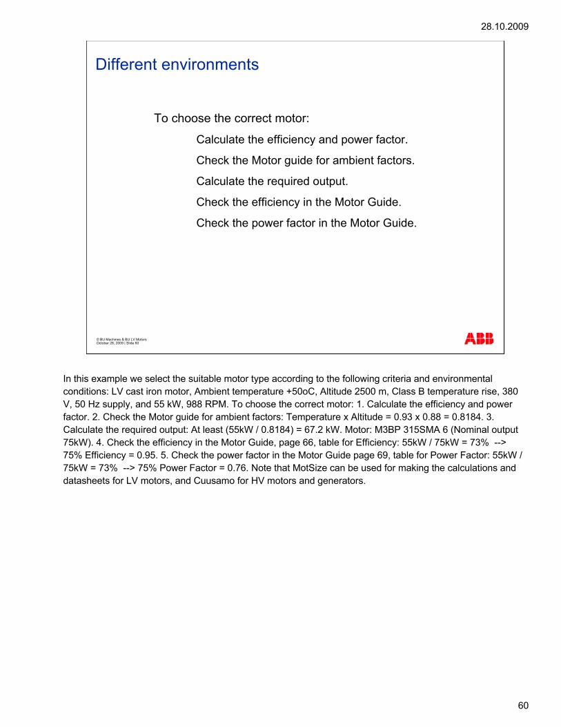
To choose the correct motor:
1. Calculate the efficiency and power factor.
2. Check the Motor guide for ambient factors.
3. Calculate the required output.
4. Check the efficiency in the Motor Guide.
5. Check the power factor in the Motor Guide.
In this example we select the suitable motor type according to the following criteria and environmental conditions: LV cast iron motor, Ambient temperature +50oC, Altitude 2500 m, Class B temperature rise, 380 V, 50 Hz supply, and 55 kW, 988 RPM. To choose the correct motor: 1. Calculate the efficiency and power factor. 2. Check the Motor guide for ambient factors: Temperature x Altitude = 0.93 x 0.88 = 0.8184. 3. Calculate the required output: At least (55kW / 0.8184) = 67.2 kW. Motor: M3BP 315SMA 6 (Nominal output 75kW). 4. Check the efficiency in the Motor Guide, page 66, table for Efficiency: 55kW / 75kW = 73% --> 75% Efficiency = 0.95. 5. Check the power factor in the Motor Guide page 69, table for Power Factor: 55kW / 75kW = 73% --> 75% Power Factor = 0.76. Note that MotSize can be used for making the calculations and datasheets for LV motors, and Cuusamo for HV motors and generators.
28.10.2009
61
© BU Machines & BU LV Motors October 28, 2009 | Slide 61
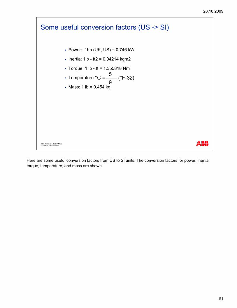
Some useful conversion factors (US -> SI)
Power: 1hp (UK, US) = 0.746 kW
Inertia: 1lb - ft2 = 0.04214 kgm2
Torque: 1 lb - ft = 1.355818 Nm
Temperature:
Mass: 1 lb = 0.454 kg
°C = (°F-32)59
Here are some useful conversion factors from US to SI units. The conversion factors for power, inertia, torque, temperature, and mass are shown.

28.10.2009
62
© BU Machines & BU LV Motors October 28, 2009 | Slide 62
Starting methods: Direct-On-Line (DOL) starting
Direct-on-line starter only required starting method when motor is connected directly to the mains supply
Preferred starting method
Limitation: high starting current
The simplest way to start a squirrel cage motor is to connect it directly to the mains supply. When it is connected directly to the mains supply, a direct-on-line (DOL) starter is the only starting equipment required. However, the limitation with this method is that it results in a high starting current. Still, it is the preferred method, unless there are special reasons for avoiding it.

28.10.2009
63
© BU Machines & BU LV Motors October 28, 2009 | Slide 63
Starting methods: Y/D starting
The graph shows a Y-D start where the starting current is about 2,2 times the nominal current. The torque values in the Y connection are much lower than in the D connection, which is why dimensioning motors for Y-D starts should be done with care, especially in bigger motors.
If it is necessary to restrict the starting current of a motor due to supply limitations, the Y/D method can be employed. This method where, for instance, a motor wound 400 VD is started with the winding Y connected will reduce the starting current to about 30 per cent of the value for direct starting. The starting torque will be reduced to about 27 per cent of the DOL value.
However, before using this method, one must first determine whether the reduced motor torque is sufficient to accelerate the load over the whole speed range.
The starting time depends on the characteristics of the load and on the starting method. Large inertias of the load will cause long starting times, which can cause overheating in the motor.
It is important to remember that the term ‘starting current’ refers to the steady-state rms value. This is the value measured when, after a few cycles, the transient phenomena have died out. The transient current, the peak value, may be about 2.5 times the steady-state starting current, but it decays rapidly. The starting torque of the motor behaves in a similar way, and this should be taken into account if the moment of inertia of the driven machine is high, since the stresses on the shaft and coupling can be very great.
Please contact your nearest sales office for the MotSize calculation program.

28.10.2009
64
© BU Machines & BU LV Motors October 28, 2009 | Slide 64
Starting methods
The different starting methods of a motor are evaluated to satisfy the voltage drop requirement.

28.10.2009
65
© BU Machines & BU LV Motors October 28, 2009 | Slide 65
Power factor
ϕ= cos*FF APPARENTUSEFUL
The relationship between the useful force and the apparent force is calculated as shown in the formula.

28.10.2009
66
© BU Machines & BU LV Motors October 28, 2009 | Slide 66
Power factor
Active power (W)
Reactivepower (VAR)
heat
ϕ
magnetic field
Q
P
Apparent power (VA)
S
The power factor (=cos j) is a relevant characteristic of each motor, defining the active power used for running the motor. This factor also depends on the need for a magnetic field to create the flux: reactive power.

28.10.2009
67
© BU Machines & BU LV Motors October 28, 2009 | Slide 67
Power factor
ϕ= cos*I*U*3PINPUT
The power factor indicates the need of reactive power Q compared with effective power P. A power factor of 1.0 means that the machine only draws effective power from the supplying network. The power factor of the induction motor should be 0.85-0.95. Power factors are likely to be lower in certain special cases, for example with multi-speed motors, motors with a high pole number, down-rated motors, and motors with frame sizes below 100. The power factor is determined by measuring the input power, voltage, and current at the rated output. The effective input power (active power) in the motor is given by the formula.

28.10.2009
68
© BU Machines & BU LV Motors October 28, 2009 | Slide 68
Benefits of a high power factor
Feasible to transmit only effective powerthrough the electrical network
Production or compensation can be made with synchronous machines or capacitors
A high power factor has the following benefits:
It is feasible to transmit only effective power through the electrical network, so if the motor draws reactive power from the network, Q should be produced somewhere near the load. Production or compensation can be made with synchronous machines or capacitors. Power companies charge more for this compensation than the price of effective power P, hence a high power factor is a desirable feature in an electrical motor.

28.10.2009
69
© BU Machines & BU LV Motors October 28, 2009 | Slide 69
28.10.2009
70
© BU LV Motors & BU Machines October 28, 2009 | Slide 70
G951e1 Basics of efficiency
28.10.2009
71
© BU Machines & BU LV Motors October 28, 2009 | Slide 71
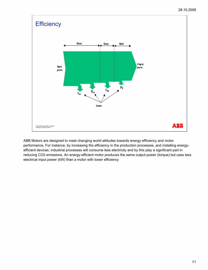
Efficiency
ABB Motors are designed to meet changing world attitudes towards energy efficiency and motor performance. For instance, by increasing the efficiency in the production processes, and installing energy-efficient devices, industrial processes will consume less electricity and by this play a significant part in reducing CO2 emissions. An energy-efficient motor produces the same output power (torque) but uses less electrical input power (kW) than a motor with lower efficiency

28.10.2009
7272
© BU Machines & BU LV Motors October 28, 2009 | Slide 72© ABB Group October 28, 2009 | Slide 72
Efficiency, definition
Efficiency is ratio between mechanical output and electrical input High efficiency means that the motor is converting electrical power to mechanical powerwith small losses
U I P cosφ
PPOutput
rpm
loadload
PPInput
LossesP∑
P Output=η
InputP
=ηPOutput
Σ PLossesPOutput +
PInput
=ηΣ−PInput PLosses
Energy supply
Efficiency is ratio between mechanical output and electrical input. To the left you can find the formula for energy efficiency.
High efficiency means that the motor is converting electrical power to mechanical power with small losses.
28.10.2009
7373
© BU Machines & BU LV Motors October 28, 2009 | Slide 73© ABB Group October 28, 2009 | Slide 73
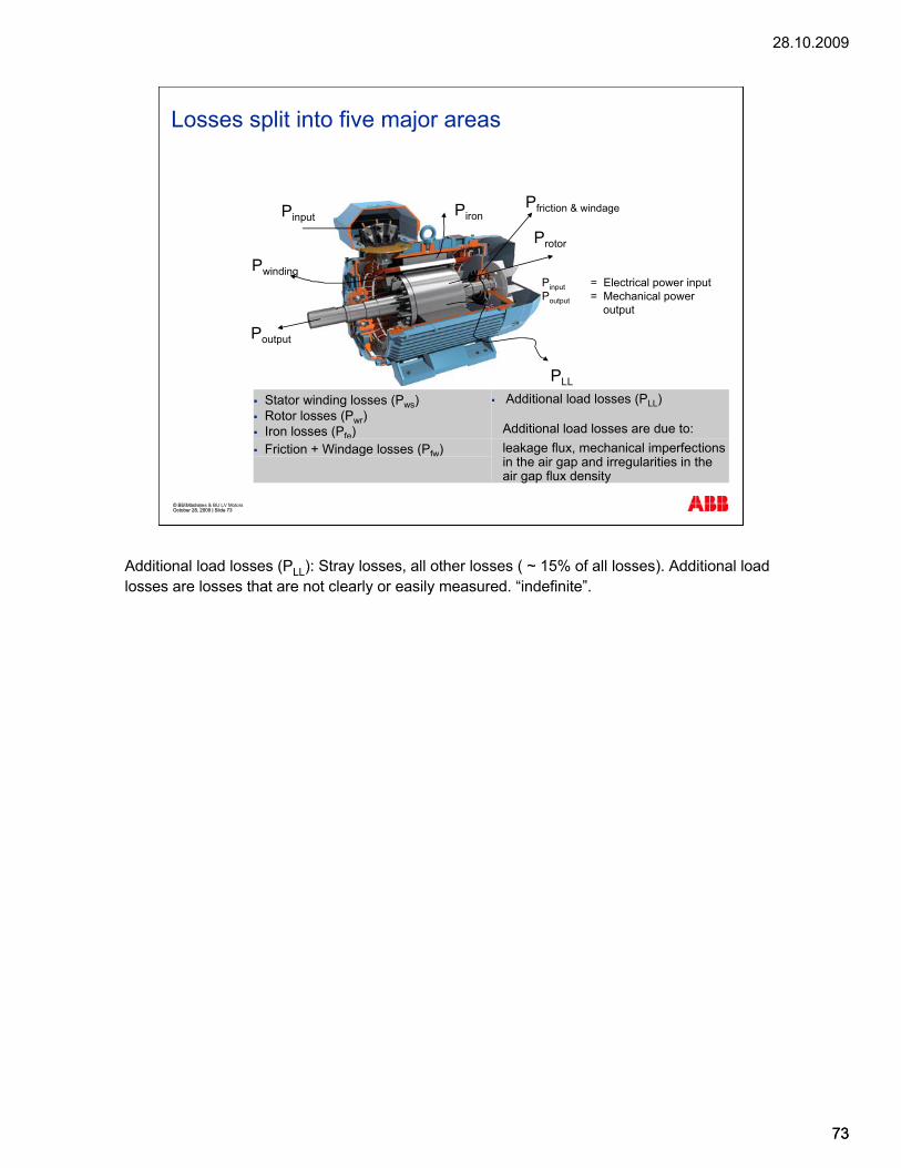
Pinput = Electrical power inputPoutput = Mechanical power
output
Pfriction & windage
Poutput
PLL
Pwinding
Pinput Piron
Protor
Stator winding losses (Pws)Rotor losses (Pwr) Iron losses (Pfe)
Additional load losses (PLL)
Additional load losses are due to:Friction + Windage losses (Pfw) leakage flux, mechanical imperfections
in the air gap and irregularities in the air gap flux density
Losses split into five major areas
Additional load losses (PLL): Stray losses, all other losses ( ~ 15% of all losses). Additional load losses are losses that are not clearly or easily measured. “indefinite”.

28.10.2009
7474
© BU Machines & BU LV Motors October 28, 2009 | Slide 74© ABB Group October 28, 2009 | Slide 74
Losses and efficiency in electrical motors
Electrical energy in(Pin)
Mechanical energy out (Pout)
Pcu1 35 %Stator winding
Pcu2 20 %Rotor winding
PFe 20%Iron
PFr Friction 10 %
PLL 15 %Additional
Pout 94 %
Mechanical energy out
Losses 6 %
PoutηPin
= 100 x [%]
Description of typical losses for a LV motor, the percentage of all losses are given based on the old standard:
Friction (P friction): Caused by the fan and bearings. This loss is independent of the load (P output) ( ~ 10% of all losses)
Iron (P iron): Needed energy to magnetize the motor ( ~ 20% of all losses)
Winding (P winding): Heat created by the current running in the windings ( ~ 35% of all losses)
Rotor (P rotor): Heat created in the rotor ( ~ 20% of all losses)
Additional load losses (PLL): All other losses ( ~ 15% of all losses). Additional load losses are losses that are not clearly or easily measured.

28.10.2009
7575
© BU Machines & BU LV Motors October 28, 2009 | Slide 75© ABB Group October 28, 2009 | Slide 75
Efficiency measurement methodsIEC 60034-2-1; 2007
IEC/EN 60034-2-1: 2007 establishes harmonized methods for determining efficiencies of rotating electrical machines and also the methods of obtaining specific losses
Covers asynchronous, synchronous and DC electrical machines
Published by the International Electrotechnical Commission in September, 2007
The efficiency measure method was published by the International Electrotechnical Commission in September, 2007.
The standard establishes harmonized methods for determining efficiencies of rotating electrical machines and also the methods of obtaining specific losses. It covers asynchronous, synchronous and DC electrical machines
28.10.2009
7676
© BU Machines & BU LV Motors October 28, 2009 | Slide 76© ABB Group October 28, 2009 | Slide 76
IEC offers two ways of measuring efficiencyDirect method
Measurement of the input power based on voltage and current, and the output power based on rotational speed and torgueNo change compared to the old IEC 60034-2
Indirect methodMeasurement of the input power and calculation of the output power based on the losses of motor
Specifies following parameters for measuring efficiency according to indirect method:
Reference temperatureThree alternatives for determining additional load losses
MeasurementAssigned valueMathematical calculation
Efficiency measurement methodsIEC 60034-2-1; 2007
Using the direct method, the MECHANICAL power on the shaft and the ELECTRICAL power on the terminals have to be measured.
The efficiency is then calculated as the ratio between the mechanical and the electrical power.
As it is very difficult and expensive to purchase and maintain equipment to measure the exact mechanical power, the indirect method is used.
Using indirect method, measurement of the torque and speed is carried out at different loads. Based on these measurements, the additional load losses are calculated.
Indirect method is also called the summation of losses method.
IEC’s new method is closer to the IEEE method

28.10.2009
7777
© BU Machines & BU LV Motors October 28, 2009 | Slide 77© ABB Group October 28, 2009 | Slide 77
Winding, rotor, iron and frictions losses can be determined from input power, voltage, current, rotational speed and torgue
Additional losses PLL are much more difficult to determine
IEC/EN 60034-2-1 specifies different methods to determine the additional losses :
Low uncertainty – measurement (IEEE 112-B & CSA390-98)
Medium uncertainty – assigned value and/or mathematicalcalculation
High uncertainty – assigned value
Which method can be used depends on the motor efficiency classdetermined by IEC/EN 60034-30
IEC 60034-2-1; 2007Losses and uncertainty of measurement
You can find more detailed information about the low, medium and high uncertainty from Table 2 in the IEC/EN 60034-2-1 standard.
IEC/EN 60034-30 defines which IE classes are connected to which method.
28.10.2009
78
© BU Machines & BU LV Motors October 28, 2009 | Slide 78

28.10.2009
79
© BU LV Motors & BU Machines October 28, 2009 | Slide 79
G951e2 Standards
28.10.2009
80
© BU Machines & BU LV Motors October 28, 2009 | Slide 80
Objectives
This course module gives an overview of the standards concerning electrical motors and generators
After successfully completing this module, you will be able to recognize the different electrical and mechanical requirements of the commonly used standards (IEC, NEMA)
This course module presents a brief overview of the standards concerning electrical motors and generators.
After successfully completing this module you will be able to recognize the different electrical and mechanical requirements of the commonly used standards IEC and NEMA.
28.10.2009
81
© BU Machines & BU LV Motors October 28, 2009 | Slide 81
Standard definitions
Standard:
technical specification or other document available to the public
based on the consolidated results of science, technology and experience
aimed at the promotion of optimum community benefits and approved by a body recognized on the national, regional or international level
The most common standards in the motor business:
IEC
EN
NEMA
Standard is defined in the following way:
"A technical specification or other document available to the public, drawn up with the cooperation and consensus or general approval of all interests affected by it based on the consolidated results of science, technology and experience, aimed at the promotion of optimum community benefits and approved by a body recognized on the national, regional or international level. In some languages the word "standard" is often used with another meaning than in this definition, and in such cases, it may refer to a technical specification which does not satisfy all the conditions given in the definition, for example: "company standard". (www.tsk.fi)
ABB low voltage standard motors and generators are of the totally enclosed, three phase squirrel cage type, built to comply with international standard IEC-standards, CENELEC and relevant VDE-regulations, and DIN-standards. Motors conforming to other national and international specifications are also available on request.
All ABB motor production units are certified to ISO 14001 international quality standard and conform to all applicable EU Directives.
ABB strongly supports the drive to harmonize European standards and actively contributes to various working groups within both IEC and CENELEC.
28.10.2009
82
© BU Machines & BU LV Motors October 28, 2009 | Slide 82
Standard definitions
Directive:
EC document issued by the European Community
aimed at harmonizing national provisions to ensure the environment and safety aspects within each State
published in the Official Journal of European Communities (OJEC)
CE as proof of conformity to the following directives:
Low Voltage Directive 73/23/EEC, amended by 93/68/EEC
EMC Directive 89/336/EEC, amended by 92/31/EEC and 93/68/EEC
A directive is an EC document issued by the European Community, the aim of which is to harmonize national provisions to ensure the environment and safety aspects within each State. A directive is published in the Official Journal of European Communities (OJEC).
Products are stamped "CE" as proof of conformity to the following directives: Low Voltage Directive 73/23/EEC, amended by 93/68/EEC and EMC Directive 89/336/EEC, amended by 92/31/EEC and 93/68/EEC. Refer to the EC Declaration of Conformity delivered with each motor.

28.10.2009
83
© BU Machines & BU LV Motors October 28, 2009 | Slide 83
Standard definitions
The International Electrotechnical Commission (IEC):
International standards and conformity assessment body for all fields of electrotechnology
Created in 1906
Head office in Geneva, Switzerland
Standards cover the whole electromechanical branch
Status of the IEC standards not strong: national electrical standards are in common use in many countries
The International Electrotechnical Commission (IEC) is the international standards and conformity assessment body for all fields of electrotechnology. It was created in 1906 and the commission's head office is situated in Geneva, Switzerland. The membership consists of more than 50 participating countries, including all the world's major trading nations and a growing number of industrializing countries.
(http://www.iec.ch/home-e.htm). The standards cover the whole electromechanical branch. The essential content of the rotating electrical machine standardization is in section 34 "Rotating electrical machines", where there are 18 parts. Each part covers a particular issue in the rotating electrical machine’s construction or performance. The main problem with the IEC standards is that their status in the world is not strong enough; national electrical standards are in common use in many countries.

28.10.2009
84
© BU Machines & BU LV Motors October 28, 2009 | Slide 84
Standard definitions
The International Organization for Standardization (ISO):
worldwide federation of national standards
non-governmental organization established in 1947
The mission:
to promote the development of standardization and related activities in the world
to facilitate the international exchange of goods and services
to develop cooperation in the spheres of intellectual, scientific, technological and economic activity
The International Organization for Standardization (ISO) is a worldwide federation of national standards bodies from approximately 140 countries, one from each country. ISO is a non-governmental organization established in 1947. The mission of ISO is to promote the development of standardization and related activities in the world with a view to facilitating the international exchange of goods and services, and to developing cooperation in the spheres of intellectual, scientific, technological and economic activity. ISO's work results in international agreements that are published as International Standards. The scope of ISO is not limited to any particular branch; it covers all technical fields except electrical and electronic engineering, which is the responsibility of IEC. The work in the field of information technology is carried out by a joint ISO/IEC technical committee.
28.10.2009
85
© BU Machines & BU LV Motors October 28, 2009 | Slide 85
Standard definitions
CENELEC:
the European Committee for Electrotechnical Standardization
established in 1973 as a non-profit-making organization under Belgian Law
officially recognized by the European Commission as the EuropeanStandards Organization in its field in Directive 83/189/EEC
works with 35,000 technical experts from 19 European countries to publish standards for the European market
CENELEC standards covering the rotating electrical machines are harmonized with the IEC standards
CENELEC is the European Committee for Electrotechnical Standardization. It was set up in 1973 as a non-profit-making organization under Belgian Law. It was officially recognized by the European Commission as the European Standards Organization in its field in Directive 83/189/EEC. Its members have worked together in the interests of European harmonization since the late 1950s, developing alongside the European Economic Community. CENELEC works with 35,000 technical experts from 19 European countries to publish standards for the European market (http://www.cenelec.org).
CENELEC standards covering the rotating electrical machines are harmonized with the IEC standards. CENELEC also includes standards for the construction and testing of electrical apparatus for use in potentially explosive atmospheres.
28.10.2009
86
© BU Machines & BU LV Motors October 28, 2009 | Slide 86
Standard definitions
The National Electrical Manufacturers Association (NEMA):
one of the leading standards development organizations in the world
attempts to promote:
the competitiveness of its member companies
the establishment and advocacy of industry policies on legislative and regulatory matters
the collection, analysis and dissemination of industry data
The National Electrical Manufacturers Association (NEMA) has been developing standards for the electrical manufacturing industry for more than 70 years and is today one of the leading standards development organizations in the world. NEMA contributes to an orderly marketplace and helps ensure public safety. NEMA also attempts to promote: the competitiveness of its member companies by providing a forum for the development of technical standards that are in the best interests of the industry and the users of its products; the establishment and advocacy of industry policies on legislative and regulatory matters that might affect the industry and those it serves; and the collection, analysis and dissemination of industry data. NEMA publishes over 200 standards and offers them for sale along with certain standards originally developed by the American National Standards Institute (ANSI) and the International Electrotechnical Commission. The association promotes safety in the manufacture and use of electrical products, provides information about NEMA to the media and the public, and represents industry interests in new and developing technologies (http://www.nema.org).

28.10.2009
87
© BU Machines & BU LV Motors October 28, 2009 | Slide 87
IEC compared to NEMA
Temperature rise:
similar rules
Tolerances:
IEC defines some tolerances, but in NEMA standards these are so-called guaranteed values
Methods of cooling and enclosure:
IEC defines a very detailed numeric coding system, but NEMA standards are more general
Starting characteristics:
differences in the starting characteristics for normal starting torque cage motors; locked rotor apparent power versus kW rating is also different.
Normally, if the NEMA standards are fulfilled, the corresponding IEC standards are also fulfilled. However, if the IEC standards are fulfilled, the corresponding NEMA standards are not necessarily fulfilled. The main differences and some comments on the similarities are discussed in the following: 1. Temperature rise: IEC and NEMA include similar rules for the adjustment of temperature rise as a function of non-standard coolant air, coolant water and/or altitude. There are some variations in the allowed temperature rise: a higher temperature rise is allowed in service factor 1.15 of the NEMA standard. Generally, a higher or equal temperature rise is allowed in the NEMA standards than in the IEC standards. Note that IEC and NEMA define the maximum allowed temperature rise in a different way when the ambient temperature is more than 40 ºC. 2. Tolerances: IEC defines some tolerances in efficiency, locked rotor current and power factor, but in the NEMA standards these are so-called guaranteed values. 3. Methods of cooling and enclosure: The IEC standards define a very detailed numeric coding system whereas the NEMA standards describe the cooling and enclosure systems more generally. 4. Starting characteristics: There are some differences in the starting characteristics for normal starting torque cage motors; locked rotor apparent power versus kW rating is also different. BU High Voltage Motors and Low voltage Motors strongly support the drive to harmonize European standards and actively contribute to various working groups within both the IEC and CENELEC.

28.10.2009
88
© BU Machines & BU LV Motors October 28, 2009 | Slide 88

28.10.2009
89
© BU LV Motors & BU Machines October 28, 2009 | Slide 89
G951e2 Electrical standards

28.10.2009
90
© BU Machines & BU LV Motors October 28, 2009 | Slide 90
Electrical standards
IEC Electrical standards:
IEC 60034-1: Rating and performance
IEC 60034-2-1: Methods for determining the losses andefficiency of rotating electrical machinery
IEC 60034-8: Terminal markings and direction of rotationof rotating machines
IEC 60034-12: (for LV only) Starting performance ofsingle-speed three phase cage induction motors
IEC/EN 60034-30: 2008: Harmonization of efficiencyclassification standards
Here is a list of the IEC Electrical standards. The IEC/EN 60034-30 standard was published by the International Electrotechnical Commission in October 2008. The standard defines new efficiency classes for motors. Target is to harmonize the different requirements for induction motor efficiency levels around the world. It provides a single international scheme for motor energy efficiency rating, measured by a common test method.

28.10.2009
91
© BU Machines & BU LV Motors October 28, 2009 | Slide 91
Motors covered in IEC/EN 60034-30: 2008
IEC/EN 60034-30 covers almost all motors (for example standard, hazardous area, marine, brake motors):
Single-speed, three-phase, 50 and 60 Hz
2, 4 or 6-pole
Rated output from 0.75 to 375 kW
Rated voltage UN up to 1000 V
Duty type S1 (continuous duty) or S3 (intermittent periodic duty) with a rated cyclic duration factor of 80% or higher
Excluded are:
Motors made solely for converter operation
Motors completely integrated into a machine (for example, pump fan or compressor) that cannot be tested separately from the machine
IEC/EN 60034-30 covers almost all motors. Excluded are motors made solely for converter operation and motors completely integrated into a machine (for example, pump fan or compressor).
28.10.2009
92
© BU Machines & BU LV Motors October 28, 2009 | Slide 92
New efficiency classes defined by IEC/EN 60034-30
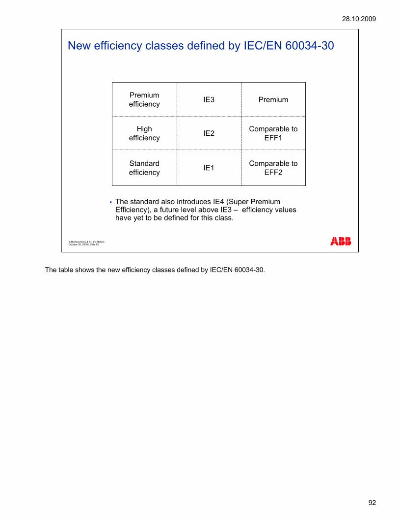
Comparable to EFF2IE1Standard
efficiency
Comparable to EFF1IE2High
efficiency
PremiumIE3Premium efficiency
The standard also introduces IE4 (Super Premium Efficiency), a future level above IE3 – efficiency values have yet to be defined for this class.
The table shows the new efficiency classes defined by IEC/EN 60034-30.
28.10.2009
93
© BU Machines & BU LV Motors October 28, 2009 | Slide 93
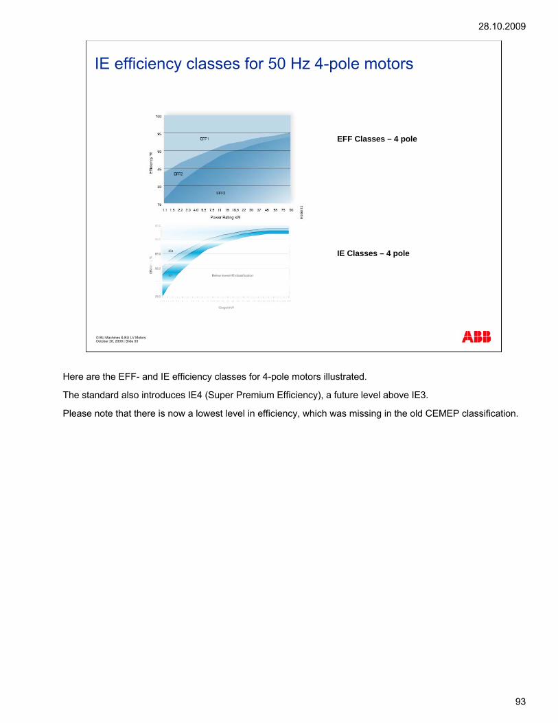
IE efficiency classes for 50 Hz 4-pole motors
IE Classes – 4 pole
EFF Classes – 4 pole
Here are the EFF- and IE efficiency classes for 4-pole motors illustrated.
The standard also introduces IE4 (Super Premium Efficiency), a future level above IE3.
Please note that there is now a lowest level in efficiency, which was missing in the old CEMEP classification.

28.10.2009
94
© BU Machines & BU LV Motors October 28, 2009 | Slide 94
Electrical standards
Type Tolerance NoteVoltage deviation ±5%
(+10K)±10%
Continuous
Short timePower factor -1/6 of (1-cos�) Min.0,02/Max.0,07Efficiency -15% of (1- �)
10% of (1- �) P2 < 50 kWP2 > 50 kW
Speed ± 20% of guaranteed slip
Overspeed 120% for 2 min.Start torque 15 to + 25%Pull-up torque -15 %Maximum torque -10% Min. 160% of MnLocked rotor current(or starting current)
+20%
The nominal tolerances given by the IEC are large and easily met; with the current manufacturing technology, the quality variation is smaller than that allowed by IEC. Some of our competitors may use this and ride with the IEC tolerances to gain benefit or hide their weaknesses. This line is not encouraged by ABB but is something worth keeping in mind.
The table shows the eelectric tolerances according to IEC 60034-1. See the graph in the next slide for term definitions.

28.10.2009
95
© BU Machines & BU LV Motors October 28, 2009 | Slide 95
Electrical standards
The graph includes definitions for the terms used in the table shown in the previous slide. The graph illustrates the starting performance of an LV motor.

28.10.2009
96
© BU Machines & BU LV Motors October 28, 2009 | Slide 96
Electrical standards
Θ
Θ Θ Θ
The duty types S1-S3 will be discussed in the following.
S1 is a continuous duty that is an operation at constant load long enough for thermal equilibrium to be reached.
S2 is a short time duty that is an operation at constant load for a given time that is shorter than the time needed to reach thermal equilibrium, followed by a rest and a de-energized period that is long enough to allow the motor to reach a temperature within 2 K of that of the coolant.
S3 is an intermittent duty that is a sequence of identical duty cycles, each including a period of operation at constant load and a rest and a de-energized period. In this duty type the cycle of the starting current does not significantly affect the temperature rise. The load period is generally not long enough for thermal equilibrium to be reached.
The illustration shows the characteristics of duty types S1, S2 and S3.
In the illustration: P = output, PV = power losses, Q = temperature, tB = load period, tS = cycle duration, and tSt = rest period.

28.10.2009
97
© BU Machines & BU LV Motors October 28, 2009 | Slide 97
NEMA MG 1
NEMA MG 1, Part 4 defines symbols for mounting dimensions
Section I - General Standard Applicable to All Machines
Section II - Small (Fractional) and Medium (Integral) Machines
Section III - Large Machines
NEMA MG 1, Part 4 defines symbols for mounting dimensions. It only defines dimensions up to frame number series 500 (shaft height 12.5" = 317.5 mm).
NEMA MG 1 consists of four sections, which are as follows:
Section I, - General Standard Applicable to All Machines includes:
Reference Standards and Definitions
Terminal Markings
Dimensions, Tolerances and Mounting
Rotating Electrical Machines - Classification of Degree of Protection Provided by Enclosures for Rotating Machines
Methods of Cooling (IC Code) and
Mechanical Vibration - Measurement, Evaluation and Limits.
Section II - Small (Fractional) and Medium (Integral) Machines includes:
Small and Medium AC Motors
Tests and Performance - AC and DC Motors
Tests and Performance - AC Motors and
Frame Assignments for Alternating Current Integral Horsepower Induction Machines.
Section III - Large Machines:
Induction Machines

28.10.2009
98
© BU Machines & BU LV Motors October 28, 2009 | Slide 98
How is the IE class marked ?
Example of the ABB’s new rating plate
Rating plate marking required
The lowest efficiency value and theassociated IE-code
Efficiency at the full rated load andvoltage (%), 75% and 50%
Year of manufacture
ABB takes the new rating plate designinto use during 2009 for all the motorsvalid according to IEC/EN 60034-30
As standard ABB will stamp 400V,415V and 690V 50Hz and theefficiency value is given for 400V
Material stainless steel
IEC/EN 60034-30 defines:
As a minimum, the lowest efficiency value and the associated IE-code (of all rated voltage/frequency/output combinations) shall always be printed on the rating plate.
ABB will follow the standard.
ABB motor design is normally optimized to 400V/50Hz operating point, and has highest efficiency in that point. Therefore 400V/50Hz value shall be the one we mark. If the motor is designed to other voltage/frequency, that will be the IE value stamped on the rating plate. All other voltage ratings, which have the same or higher efficiency may be in the same rating plate. Other ratings having lower IE value, need their own separate rating plate.
Transit period will be the end of 2009. By that time efficiency logo eff1 or eff2 is targeted to be removed and new IEC/EN 60034-30 defined IE rating must be in all our motors.
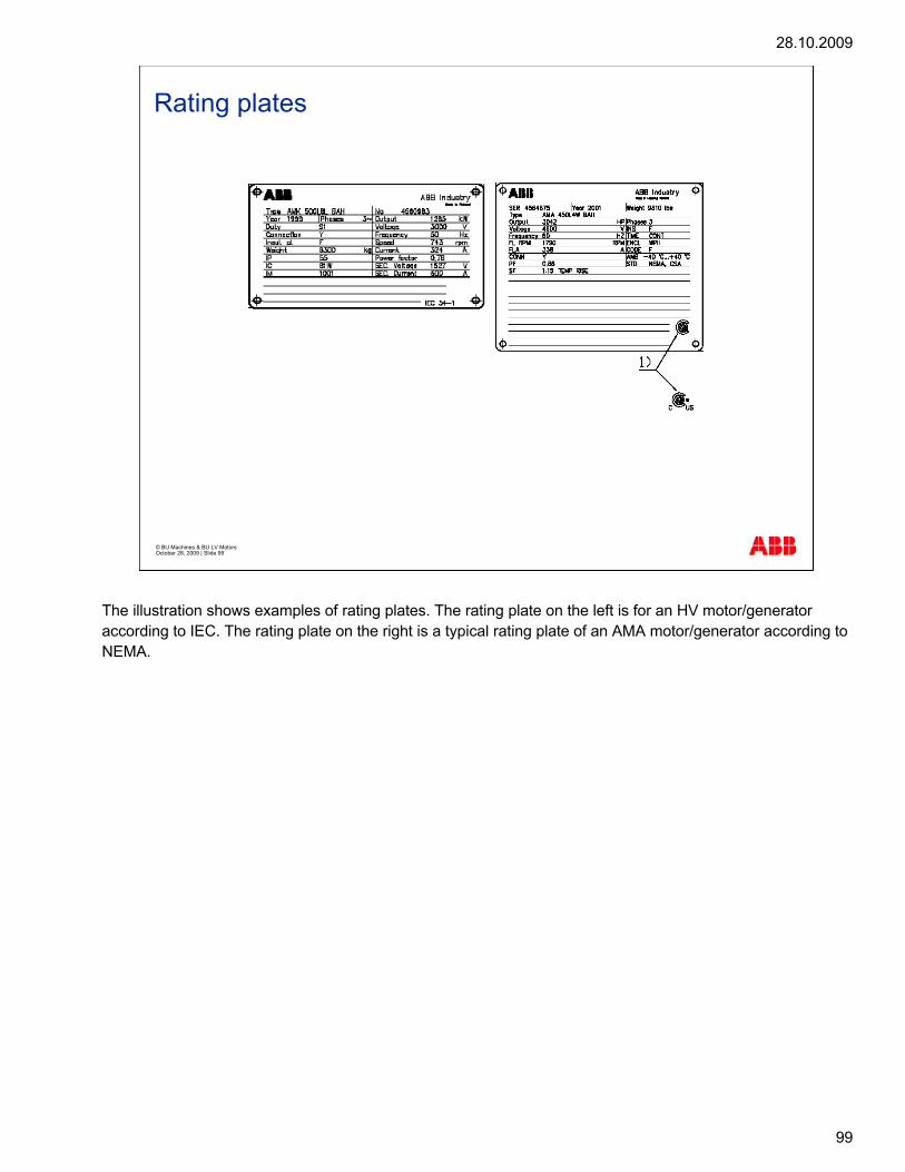
28.10.2009
99
© BU Machines & BU LV Motors October 28, 2009 | Slide 99
Rating plates
The illustration shows examples of rating plates. The rating plate on the left is for an HV motor/generator according to IEC. The rating plate on the right is a typical rating plate of an AMA motor/generator according to NEMA.

28.10.2009
100
© BU Machines & BU LV Motors October 28, 2009 | Slide 100
Rating plates
The rating plate on the right is for an LV motor according to NEMA.
28.10.2009
101
© BU Machines & BU LV Motors October 28, 2009 | Slide 101
Direction of rotation and terminal marking
According to the IEC 60034-8 standard, the followingterminal markings are required:
windings are marked by letters (U, V, W),
end points are marked with an additional numericalsuffix (U1, V1, W1), and
similar windings of a group are marked with a numericalprefix (1U, 1V, 1W).
Direction of rotation is the one observed or clockwise
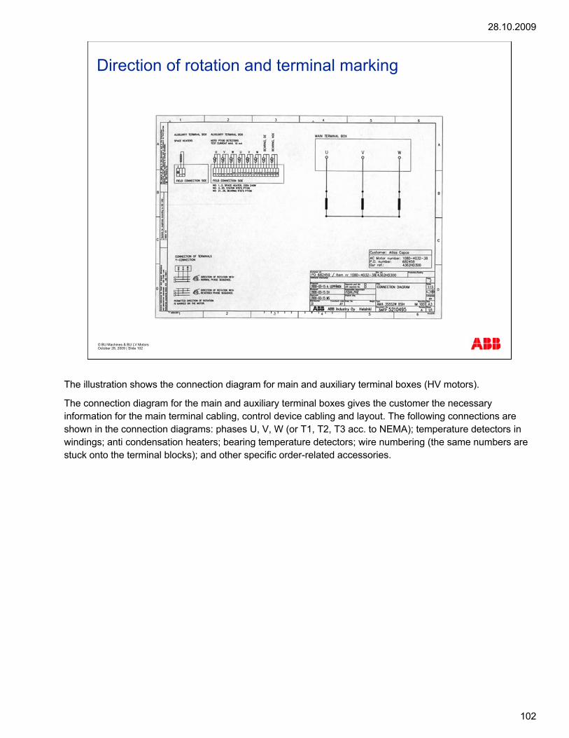
28.10.2009
102
© BU Machines & BU LV Motors October 28, 2009 | Slide 102
Direction of rotation and terminal marking
The illustration shows the connection diagram for main and auxiliary terminal boxes (HV motors).
The connection diagram for the main and auxiliary terminal boxes gives the customer the necessary information for the main terminal cabling, control device cabling and layout. The following connections are shown in the connection diagrams: phases U, V, W (or T1, T2, T3 acc. to NEMA); temperature detectors in windings; anti condensation heaters; bearing temperature detectors; wire numbering (the same numbers are stuck onto the terminal blocks); and other specific order-related accessories.

28.10.2009
103
© BU Machines & BU LV Motors October 28, 2009 | Slide 103
Direction of rotation and terminal marking
L3L2L1
W1V1U1
PE
V2U2W2
U1 V1 W1
L3L2L1
W1V1U1
PE
Connection triangleD-SchaltungD-connection
Schema de branchementAnschluss-SchemaDiagram of connection
Branchement des bornesAnschluss des MotorsConnection of terminals
W2 U2 V2V2U2W2
No du moteurMaschine NrMotor No
ABB Oy, Electrical Machines3GZF321100-1 C
Direction de rotation avec branchement ci-dessusDrehrichtung nach SchaltbildDirection of rotation with phase sequence shown in picture
Connection etoileY-SchaltungY-connection
Direction de rotation avec sequence de phase reverséeDrehrichtung mit umgekehrter PhasenfolgeDirection of rotation with reversed phase sequence
LV Motors
The illustration shows a connection diagram for a main terminal box (LV motors). LV motors are supplied with a separate connection diagram for auxiliaries.
28.10.2009
104
© BU Machines & BU LV Motors October 28, 2009 | Slide 104
NEMA MG 1, Part 2 - Terminal Marking
Terminal markings:
line - L1, L2, L3, L4, etc.
stator - T1, T2, T3, T4, etc.
auxiliary markings, e.g. space heater H1, H2, H3, H4
NEMA MG 1, Part 2 covers terminal markings, direction of rotation, and the relation between the terminal markings and the direction of the rotation. The following terminal markings are covered: line (L1, L2, L3, L4, etc.); stator (T1, T2, T3, T4, etc.); also covers auxiliary markings, e.g. space heater H1, H2, H3, H4. The standard direction of rotation for AC generators is clockwise when facing the end of the motor/generator opposite the drive end (standard ABB practice is the IEC method). Terminal marking of polyphase induction motors/generators are not related to the direction of rotation.

28.10.2009
105
© BU Machines & BU LV Motors October 28, 2009 | Slide 105
Direction of rotation and terminal marking
The illustration shows the connection diagram for main terminal box according to NEMA (LV motors).

28.10.2009
106
© BU Machines & BU LV Motors October 28, 2009 | Slide 106

28.10.2009
107
© BU LV Motors & BU Machines October 28, 2009 | Slide 107
G951e2 Mechanical standards

28.10.2009
108
© BU Machines & BU LV Motors October 28, 2009 | Slide 108
Mechanical standardsShaft height
Shaftheight
Shaft height is the distance from the centre line of the shaft to the bottom of the feet. For example, the motor type M3BP 315SMB 4 B3 has a shaft height of 315 mm.
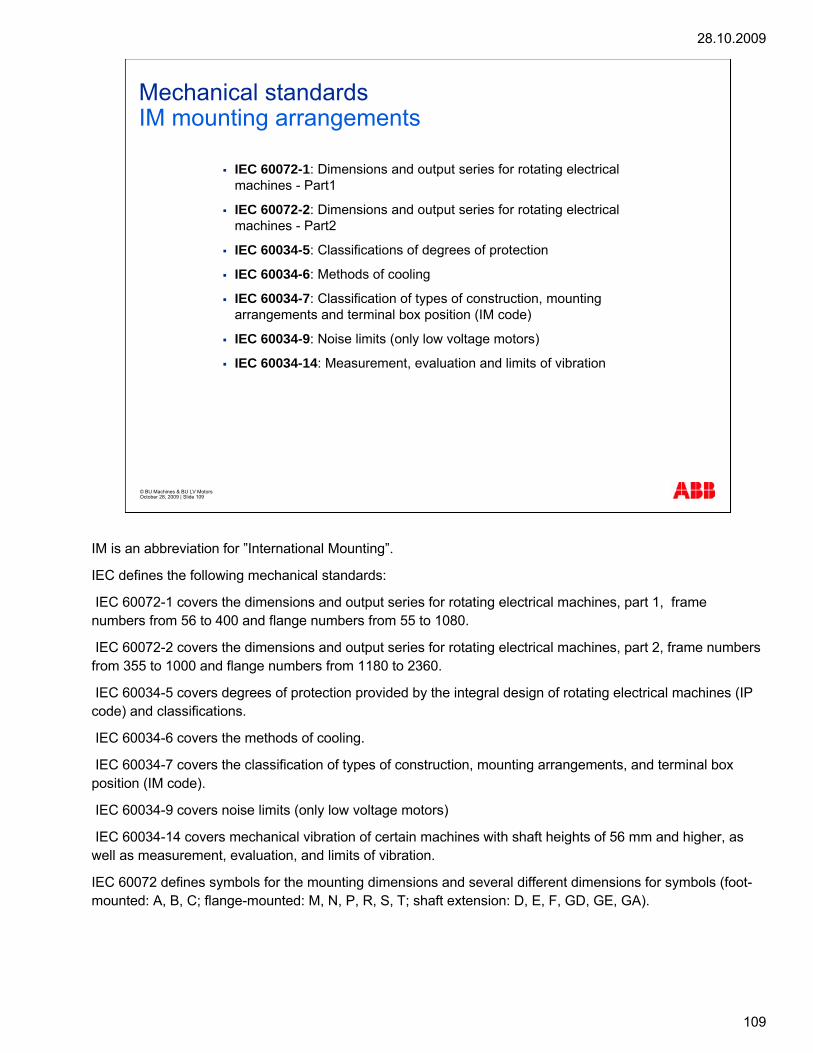
28.10.2009
109
© BU Machines & BU LV Motors October 28, 2009 | Slide 109
Mechanical standardsIM mounting arrangements
IEC 60072-1: Dimensions and output series for rotating electricalmachines - Part1
IEC 60072-2: Dimensions and output series for rotating electricalmachines - Part2
IEC 60034-5: Classifications of degrees of protection
IEC 60034-6: Methods of cooling
IEC 60034-7: Classification of types of construction, mountingarrangements and terminal box position (IM code)
IEC 60034-9: Noise limits (only low voltage motors)
IEC 60034-14: Measurement, evaluation and limits of vibration
IM is an abbreviation for ”International Mounting”.
IEC defines the following mechanical standards:
IEC 60072-1 covers the dimensions and output series for rotating electrical machines, part 1, frame numbers from 56 to 400 and flange numbers from 55 to 1080.
IEC 60072-2 covers the dimensions and output series for rotating electrical machines, part 2, frame numbers from 355 to 1000 and flange numbers from 1180 to 2360.
IEC 60034-5 covers degrees of protection provided by the integral design of rotating electrical machines (IP code) and classifications.
IEC 60034-6 covers the methods of cooling.
IEC 60034-7 covers the classification of types of construction, mounting arrangements, and terminal box position (IM code).
IEC 60034-9 covers noise limits (only low voltage motors)
IEC 60034-14 covers mechanical vibration of certain machines with shaft heights of 56 mm and higher, as well as measurement, evaluation, and limits of vibration.
IEC 60072 defines symbols for the mounting dimensions and several different dimensions for symbols (foot-mounted: A, B, C; flange-mounted: M, N, P, R, S, T; shaft extension: D, E, F, GD, GE, GA).

28.10.2009
110
© BU Machines & BU LV Motors October 28, 2009 | Slide 110
Mechanical standardsIM mounting arrangements
The diagram shows an example of designations according to Code II.
The first characteristic numeral indicates the basic construction of the motor/generator (mounting to foundation, bearing arrangement). The second and third numerals indicate more detailed construction, depending on the first numeral. The fourth numeral indicates the amount and shape of the shaft extension(s).
IEC 60034-7 specifies two ways of stating how a motor is mounted.
According to Code I, an alpha-numeric designation is applicable to motors/generators with end shield bearing(s) and only one shaft extension.
According to Code II, an all-numeric designation is applicable to a wider range of types of motors/generators, including types covered by Code I.

28.10.2009
111
© BU Machines & BU LV Motors October 28, 2009 | Slide 111
Mechanical standardsIM mounting arrangements
Code II First numeral Second and third numeral
Fourth numeral
Motor/generator type
Code I Sketch
IM 1001 Foot-mounted motors/generators with end shield bearing(s) only
Two bearings, normal feet, feet down, shaft horizontal
One cylindrical shaft extension
HXR, AMA, AMK
IM B3
IM 3011 Flange-mounted motors/generators with end shield bearing(s) only, with a flange as part of an end shield
Two bearings, flange at D-end, access to back of flange, face of flange faces towards D-end, shaft vertical downwards
One cylindrical shaft extension
HXR IM V1
IM 4011 Flange-mounted motors/generators with end shield bearing(s) only, with a flange not part of an end shield but an integral part of the frame or other component
Two bearings, flange at D-end, access to back of flange, face of flange faces towards D-end, shaft vertical downwards
One cylindrical shaft extension
AMA, AMK IM V10
The table shows examples of common HV motor mounting arrangements.

28.10.2009
112
© BU Machines & BU LV Motors October 28, 2009 | Slide 112
Mechanical standardsIM mounting arrangements
Examples of common LV motor mounting arrangements are shown in this slide.
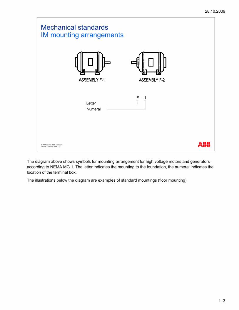
28.10.2009
113
© BU Machines & BU LV Motors October 28, 2009 | Slide 113
Mechanical standardsIM mounting arrangements
LetterNumeral
F - 1
The diagram above shows symbols for mounting arrangement for high voltage motors and generators according to NEMA MG 1. The letter indicates the mounting to the foundation, the numeral indicates the location of the terminal box.
The illustrations below the diagram are examples of standard mountings (floor mounting).

28.10.2009
114
© BU Machines & BU LV Motors October 28, 2009 | Slide 114
International StandardsMethod of Cooling (IC code, short one normally used)
IC = International coolingA = Air as coolantW = Water as coolant
The diagram shows the method of cooling for low voltage motors according to IEC 60034-6.
ABB can deliver motors as below:
IC 410 Totally enclosed motor without fan
IC 411: Totally enclosed standard motor, frame surface cooled with fan
IC 416: Totally enclosed motor with auxiliary fan motor
IC 418: Totally enclosed motor, frame surface cooled without fan
IC 01 : Open motors
IC 31W: Inlet and outlet pipe or duct circulated: water cooled
Note: Motors without fan can deliver same output power provided installation are according to IC 418.

28.10.2009
115
© BU Machines & BU LV Motors October 28, 2009 | Slide 115
International StandardsMethod of Cooling
COMPLETE DESIGNATION
SIMPLIFIED DESIGNATION
IC 8 A
IC 8
1 W 7
1 W
Code lettersCircuit arrangementPrimary coolantMethod of movement of primary coolantSecondary coolantMethod of movement of secondary coolant
The diagram shows the method of cooling for high voltage motors and generators.
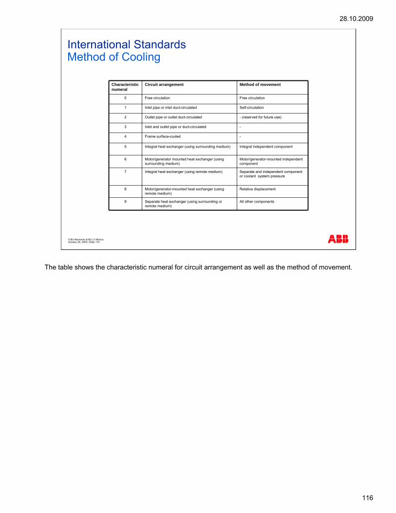
28.10.2009
116
© BU Machines & BU LV Motors October 28, 2009 | Slide 116
International StandardsMethod of Cooling
Characteristic numeral
Circuit arrangement Method of movement
0 Free circulation Free circulation
1 Inlet pipe or inlet duct-circulated Self-circulation
2 Outlet pipe or outlet duct-circulated - (reserved for future use)
3 Inlet and outlet pipe or duct-circulated -
4 Frame surface-cooled -
5 Integral heat exchanger (using surrounding medium) Integral independent component
6 Motor/generator mounted heat exchanger (using surrounding medium)
Motor/generator-mounted independent component
7 Integral heat exchanger (using remote medium) Separate and independent component or coolant system pressure
8 Motor/generator-mounted heat exchanger (using remote medium)
Relative displacement
9 Separate heat exchanger (using surrounding or remote medium)
All other components
The table shows the characteristic numeral for circuit arrangement as well as the method of movement.

28.10.2009
117
© BU Machines & BU LV Motors October 28, 2009 | Slide 117
International StandardsMethod of Cooling
Characteristic letter CoolantA AirF FreonH HydrogenN NitrogenC Carbon dioxideW WaterU OilS Any other coolantY Coolant not yet selected
The table shows the characteristic letter for each coolant.
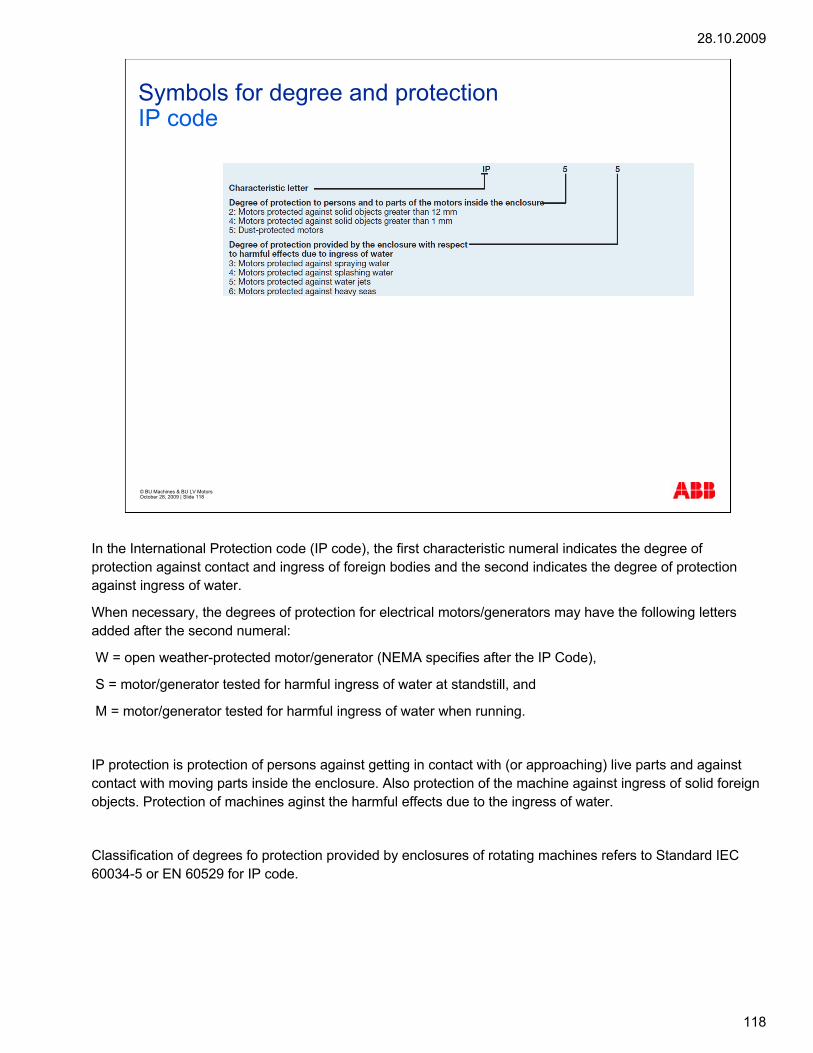
28.10.2009
118
© BU Machines & BU LV Motors October 28, 2009 | Slide 118
Symbols for degree and protectionIP code
IEC 60034-5 and NEMA MG 1 Part 5
In the International Protection code (IP code), the first characteristic numeral indicates the degree of protection against contact and ingress of foreign bodies and the second indicates the degree of protection against ingress of water.
When necessary, the degrees of protection for electrical motors/generators may have the following letters added after the second numeral:
W = open weather-protected motor/generator (NEMA specifies after the IP Code),
S = motor/generator tested for harmful ingress of water at standstill, and
M = motor/generator tested for harmful ingress of water when running.
IP protection is protection of persons against getting in contact with (or approaching) live parts and against contact with moving parts inside the enclosure. Also protection of the machine against ingress of solid foreign objects. Protection of machines aginst the harmful effects due to the ingress of water.
Classification of degrees fo protection provided by enclosures of rotating machines refers to Standard IEC 60034-5 or EN 60529 for IP code.

28.10.2009
119
© BU Machines & BU LV Motors October 28, 2009 | Slide 119
Protection Classes (IEC 60034-5)
The table shows the explanations of the protection codes.

28.10.2009
120
© BU Machines & BU LV Motors October 28, 2009 | Slide 120
Protection Classes (IEC 60034-5)
Protection Brief Description Definition Cooling Motor/generator type
NEMA
IP23 Motor/generator protectedagainst solid objectsgreater than 50 mm(1.9685 in)
Motor/generator protectedagainst sprayingwater
Contact with or approach to live or moving parts inside theenclosure by fingers or similar objects not exceeding 80mm (3.1496 in) in length.Ingress of solid objects exceeding 12 mm (0.4724 in) indiameter.Water falling as a spray at an angle up to 60° from verticalshall have no harmful effect.
IC01 AMA, AMK ODP
IP24W(IEC)
IPW24(NEMA)
Motor/generator protectedagainst solid objectsgreater than 50 mm(1.9685 in)
Motor/generator protectedagainst sprayingwater
Contact with or approach to live or moving parts inside theenclosure by fingers or similar objects not exceeding 80mm (3.1496 in) in length.Ingress of solid objects exceeding 12 mm (0.4724 in) indiameter.Water splashing against the machine from any directionshall have no harmful effect.Weather-protected so designed that ingress of rain, snowand airborne particles into the electrical parts is reduced.
IC01 AMA, AMK WP IWP II
IP55 Dust-protectedmotor/generator
Motor/generator protectedagainst water jets
Contact with or approach to live or moving parts inside theenclosure.Ingress of dust is not totally prevented but dust does notenter in sufficient quantity to interfere with satisfactoryoperation of the machine.Water projected by a nozzle against the machine from anydirection shall have no harmful effect.
IC411
IC611
IC81W
HXR
AMA, AMK
AMA, AMK
TEFC
TEAAC
TEWAC
The table shows the standard IP protection for high voltage motors and generators.

28.10.2009
121
© BU Machines & BU LV Motors October 28, 2009 | Slide 121
Degrees of protectionIK code
IK code is the classification of degrees or protection provided by enclosure for motors against external mechanical impacts.
Classification of degrees fo protection provided by enclosures of rotating machines refers to Standard EN 50102 for IK code.

28.10.2009
122
© BU Machines & BU LV Motors October 28, 2009 | Slide 122
Insulation
ABB uses class F insulation systems, which, with temperature rise B, is the most common requirement among industry today.
The use of Class F insulation with Class B temperature rise gives ABB products a 25° C safety margin. This can be used to increase the loading by up to 12 per cent for limited periods, to operate at higher ambient temperatures or altitudes, or with greater voltage and frequency
tolerances. It can also be used to extend insulation life. For instance, a 10 K temperature reduction will extend the insulation life.
Class F insulation system
– Max ambient temperature 40° C
– Max permissible temperature rise 105 K
– Hotspot temperature margin + 10 K
Class B rise
•Max ambient temperature 40° C
•Max permissible temperature rise 80 K
•Hotspot temperature margin + 10 K
Insulation system temperature class
•Class F 155° C
•Class B 130° C
•Class H 180° C

28.10.2009
123
© BU Machines & BU LV Motors October 28, 2009 | Slide 123
Frequency converter drivesCustomer values
Squirrel cage induction motors offer excellent availability, reliability and efficiency. With a frequency converter – a variable speed drive (VSD) – the motor will deliver even better value. A variable speed drive motor can be started softly with low starting current, and the speed can be controlled and adjusted to suit the application demand without steps over a wide range. Also the use of a frequency converter together with a squirrel cage motor usually leads to remarkable energy and environmental savings.
Speed control has several benefits: it allows accurate process control, and thus creates better end product quality. Speed control also creates less stress to mechanics and electrical network due to soft starting and precise control. It increases production capacity without additional investments.
An AC induction motor, that is, an asynchronous squirrel cage AC motor, is most commonly used in industry. It has some basic advantages like robust design, simple construction, high IP class, and so on. An asynchronous motor needs frequency converter to control its speed.
A modern frequency converter has many advanced protection features that protect the drive itself, equipment connected to the drive and even the production process. It has inbuilt programmability that allows it to control a production process without an additional external controller, or PLC. Programmability means the user can fine tune the variable speed drive, or VSD, to get the most out of the whole equipment.
Requirements for the flexibility and accuracy of external control methods can best be fulfilled with a modern VSD which can be connected to just about any fieldbus or analog or digital control signal. Even remote monitoring via the Internet is possible.

28.10.2009
124
© BU Machines & BU LV Motors October 28, 2009 | Slide 124
Rotor Construction – Balancing
Standards for mechanical vibration:
ISO 1940/1: Balance quality requirements for rigidrotors, Part 1
ISO 1940/2: Balance quality requirements for rigidrotors, Part 2
ISO 11342: Methods and criteria for the balancing offlexible rotors
Balancing quality grades:
G2, 5 for medium and large armatures with specialrequirements
G6, 3 for medium and large armatures without specialrequirements
The following standards cover the balancing of the rotor construction:
ISO 1940/1 for mechanical vibration covers the balance quality requirements for rigid rotors in Part 1: Determination of permissible residual unbalance.
ISO 1940/2 for mechanical vibration covers the balance quality requirements for rigid rotors in Part 2: Balance errors.
ISO 11342 for mechanical vibration covers the methods and criteria for the balancing of flexible rotors.
Imbalance is a condition, which exists in a rotor when a vibratory force or motion is imparted to its bearings as a result of centrifugal forces.
The balancing quality grades are:
G2, 5 for medium and large armatures with special requirements and
G6, 3 for medium and large armatures without special requirements.
As standard, rotors are balanced with half key; the coupling must also be balanced with half key. The balancing procedure is permanently marked on the shaft end with 'H' (H = half key, F = full key).
28.10.2009
125
© BU Machines & BU LV Motors October 28, 2009 | Slide 125
Vibration
Vibration is a response of a system to an internal orexternal stimulus causing it to oscillate or pulsate
Three important parameters:
frequency
amplitude
phase
Vibration is the response of a system to an internal or external stimulus causing it to oscillate or pulsate. While it is commonly thought that vibration itself damages motors and structures, it does not. The damage is done by dynamic stresses that cause fatigue in the materials. The dynamic stresses are included in the vibration.
Vibration has three important parameters, which can be measured:
Frequency, that is, how many times does the motor or structure vibrate per minute or per second.
Amplitude, that is, how much is the vibration in microns, mm/s or g's.
Phase, that is, how is the member vibrating in relation to the reference point.
The following standards cover mechanical vibration:
ISO 10816- Mechanical vibration: Evaluation of machine vibration by measurement of non-rotating parts,
NEMA MG 1, Part 7: Mechanical vibration - Measurement, evaluation and limits,
ISO 7919: Mechanical vibration of non-reciprocating machines - Measurement of rotating shafts and evaluation criteria, and
IEC 60034-14: Mechanical vibration of certain machines with shaft heights of 56 mm and higher -Measurement, evaluation and limits.

28.10.2009
126
© BU Machines & BU LV Motors October 28, 2009 | Slide 126
M, IP, IC
International Standards CEI EN 60034:
CEI EN 60034- 5: degrees of protection provided bythe integral design of rotating electrical machines (IPcode) – Classification,
CEI EN 60034- 5: degrees of protection provided bythe integral design of rotating electrical machines (IPcode) – Classification, and
CEI EN 60034- 7: classification of types ofconstruction, mounting arrangements and terminal boxposition (IM Code).
The following issues are covered by the International Standards CEI EN 60034:
CEI EN 60034-5 covers the degrees of protection provided by the integral design of rotating electrical machines (IP code) – Classification,
CEI EN 60034-5 covers the degrees of protection provided by the integral design of rotating electrical machines (IP code) – Classification, and
CEI EN 60034-7 covers the classification of types of construction, mounting arrangements and terminal box position (IM Code).

28.10.2009
127
© BU Machines & BU LV Motors October 28, 2009 | Slide 127