g3po - mickeynowell.commickeynowell.com/sitebuildercontent/sitebuilderfiles/g3pos092506.pdf · g3po...
TRANSCRIPT

© Copyright 2005, Charles M. Nowell, Jr. 1 All Commercial Rights Reserved.
G3PO (Gyrocopter 3.0) Electric Gyrocopter
© Copyright 2005, Charles M. Nowell, Jr. 2 All Commercial Rights Reserved.
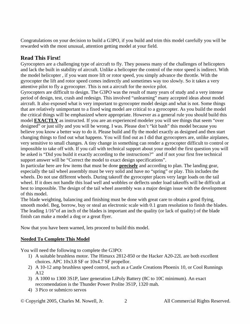
Congratulations on your decision to build a G3PO, if you build and trim this model carefully you will be rewarded with the most unusual, attention getting model at your field. Read This First! Gyrocopters are a challenging type of aircraft to fly. They possess many of the challenges of helicopters and lack the built in stability of aircraft. Unlike a helicopter the control of the rotor speed is indirect. With the model helicopter , if you want more lift or rotor speed, you simply advance the throttle. With the gyrocopter the lift and rotor speed comes indirectly and sometimes way too slowly. So it takes a very attentive pilot to fly a gyrocopter. This is not a aircraft for the novice pilot. Gyrocopters are difficult to design. The G3PO was the result of many years of study and a very intense period of design, test, crash and redesign. This involved “unlearning” many accepted ideas about model aircraft. It also exposed what is very important to gyrocopter model design and what is not. Some things that are relatively unimportant to a fixed wing model are critical to a gyrocopter. As you build the model the critical things will be emphasized where appropriate. However as a general rule you should build this model EXACTLY as instructed. If you are an experienced modeler you will see things that seem “over designed” or just silly and you will be wrong. I was. Please don’t “kit bash” this model because you believe you know a better way to do it. Please build and fly the model exactly as designed and then start changing things to find out what happens. You will find out as I did that gyrocopters are, unlike airplanes, very sensitive to small changes. A tiny change in something can render a gyrocopter difficult to control or impossible to take off with. If you call with technical support about your model the first question you will be asked is “Did you build it exactly according to the instructions?” and if not your first free technical support answer will be “Correct the model to exact design specifications”. In particular here are few items that must be done precisely and according to plan. The landing gear, especially the tail wheel assembly must be very solid and have no “spring” or play. This includes the wheels. Do not use different wheels. During takeoff the gyrocopter places very large loads on the tail wheel. If it does not handle this load well and wobbles or deflects under load takeoffs will be difficult at best to impossible. The design of the tail wheel assembly was a major design issue with the development of this model. The blade weighting, balancing and finishing must be done with great care to obtain a good flying, smooth model. Beg, borrow, buy or steal an electronic scale with 0.1 gram resolution to finish the blades. The leading 1/16”of an inch of the blades is important and the quality (or lack of quality) of the blade finish can make a model a dog or a great flyer. Now that you have been warned, lets proceed to build this model. Needed To Complete This Model You will need the following to complete the G3PO:
1) A suitable brushless motor. The Himaxx 2812-850 or the Hacker A20-22L are both excellent choices. APC 10x3.8 SF or 10x4.7 SF propellor.
2) A 10-12 amp brushless speed control, such as a Castle Creations Phoenix 10, or Cool Runnings A12
3) A 1000 to 1300 3S1P, later generation LiPoly Battery (8C to 10C minimum). An exact reccomendation is the Thunder Power Prolite 3S1P, 1320 mah.
4) 3 Pico or submicro servos

© Copyright 2005, Charles M. Nowell, Jr. 3 All Commercial Rights Reserved.
5) Micro receiver 6) Foam safe CA glue 7) Optional : DuBro micro EZ connectors for aileron and elevator.
Building You can build the sub assemblies in any order. Final assembly will of course require the sub-assemblies. The assumption is that you are an experienced modeler. Where some portion of the design is non-critical, this will be pointed out such that builders preference may be satisfied. Glues will not be specified unless they are critical to a step, and this will be pointed out. Chassis. Glue the main mast, motor mount stick, landing gear keel, and 1/8 lite ply fuselage together over the plan. Make sure the angles are correct. Get the angles right. Wrap sandpaper around the tailboom and use it to true up the grove in the bottom of the keel and main mast blocks. Cut the trailing of the fin and the leading edge of the rudder at an angle as shown in the photo. The angles should create a “V” on the right side of the fin/rudder. Round of the other edges of the fin and rudder. Lay the fin and rudder flat with
the “V” down and apply clear tape to the hinge line. Fold the rudder all the way back and apply tape in the “V”. It helps to leave a small gap so the two pieces of tape can stick together at the hinge line. 3M Brand “Blenderm” (tm) works well for the hinge.

© Copyright 2005, Charles M. Nowell, Jr. 4 All Commercial Rights Reserved.
Glue the balsa doublers to the fin, letting them extend about 1/6” inch below the foam. Wrap sandpaper around the boom and sand the bottom of the fin to match the boom. Join the two tailboom pieces, the 15-1/4” piece and the 10” piece of ¼” inside diameter tube, using the ¼” dowel as a joiner. You may have to sand the ends flush. Make sure the tail boom is straight when gluing. Glue the fin to the tailboom with the hinge line about 1/16” inch behind the end of the tail boom. Glue the ¼” by 1” dowel into the end of the tailboom.
Hold the tail wheel bracket in place on the side of the tailboom such that the centerline of the wire lines up with the hinge line of the rudder. Drill the pilot holes for the #2 screws and washers. Screw the tail wheel bracket to the tailboom. Slip the plastic tube over the tiller arm and glue this to the rudder. Wrap a piece of tape over the bottom of the rudder and the tube to secure it. Push the 1/16” wheel collar up to the bottom of the tail wheel bracket and tighten. Install the tail wheel with the collar. Making sure the tailboom extends ¼” beyond the landing gear keel and that the rudder is vertical compared with the main mast, glue the tailboom to the main chassis. Glue up the four main landing gear pieces. Put the two pieces with the slots in the middle. (Note: some early parts are not symmetrical, they are marked, so put the marks the same direction, otherwise the center hole won’t line up.) Use epoxy and make sure every thing is aligned. When cured, use a 5/32” drill bit and drill open up the square hole slightly to fit the landing gear legs, but dont’ glue them yet. Use an XActo knife or reamer and open the main hole on an angle so that the landing gear block fits over the tailboom and flat to the keel piece. Slip the landing gear legs into the landing gear block without glue, set the chassis on flat surface and align so the main mast is vertical. Now glue the landing gear block to the fuse. If you want to make the landing gear removeable don’t glue but screw the landing gear block to the keel with a 1” long #4 wood screw after drilling pilot holes to avoid splitting. Take the 2mm wire axles and measure in the thickness of the wheel and wheel collar and make about a 20 degree bend. Slip the longer end into the ends of the landing gear legs. Adjust the bend on the wires until they are straight out and level to the ground. When satisifed roughen up the long portion of the axle with 50 grit sandpaper or nick the wires with diagonal cutters to provide something for the glue to grab. Glue the axles into the ends of the landing gear struts up to the bend with thick CA. Use the kevlar thread on each gear leg and wrap the last 1/8” of the gear leg to keep it from splitting. Secure with thin CA. Install the wheels and the 2mm wheel collars. Bend the axles as

© Copyright 2005, Charles M. Nowell, Jr. 5 All Commercial Rights Reserved.
necessary to get the wheels slightly cambered out and toed in. Adjust the wheel track until satisfied and then secure the landing gear legs into the landing gear blocks with thin CA.
Glue the ply reinforcements and the rudder horn to the rudder. Make sure the rudder horn is centered on the sharp edge, not the centerline. Drill a shallow (1/16” deep ) 1/16” hole in the main mast for the tail boom brace. Glue
the 1/16” dowel (toothpick) in the tail boom brace. Glue the tail boom brace on, in the hole. Take the heavy thread and wrap the aft tail boom brace joint and soak with CA. Congratulations! the main chassis is complete.

© Copyright 2005, Charles M. Nowell, Jr. 6 All Commercial Rights Reserved.
Head The head has a strengthening modification that can be done during construction or later after a few “mishaps”. Its probably easier to do during construction. Take the head center hub ( the part with the bearings) and attach the main head plate by snapping it onto the bearings. Take an Xacto and cut a small (1/16”) notch out of the head blade diagonal bracing directly above the bearings. Line this up with the little grove on the outside of the bearing holders. Now take the kevlar thread and make 3 or 4 turns around the head and the bearings, effectively lashing the bearings into the head. Tie off securely on the top of the head ( an extra pair of hands will help here) and then apply a couple tiny drops of CA to the thread on the top of the head only. Be careful not to flood the CA or get any in the bearings. If you happen to get CA in the bearings (not like I’ve ever done this or anything) you can soak them in acetone or debonder until they free up.
Put on the flybar plate (set screws down) and slide the flybar in place. Make sure that it is centered (use a caliper if you have one) and tighten the set screws (1.5mm). Now snap on the little dog bone links that attach the head to the flybar plate. Install the flybar paddles so that they are level with the flybar plate with the leading edge facing forward in the clockwise rotation direction. Slip the follower link on the center hub (note the alignment) and line up the hole with the hub. Connect the smaller of the dog bone links to the flybar plate and the longer of the inner arms on the swashplate. Make sure the links are on the flat side (forward clockwise direction) of the follower link. Slide the whole assembly, swashplate first onto the main shaft. Use a pin to align the follower link, the center hub and the shaft, then press the 1mm music wire pin through the head assembly/main shaft. Slide on a 3mm wheel collar, then a bearing, then the black gearbox, another bearing, the small 3mm washer and finally another 3mm wheel collar. Adjust the upper wheel collar until the bottom of the swashplate is ½” from the top of the gearbox. Wiggle the swashplate around to make sure it will clear the wheel collar. Once satisfied tighten the set

© Copyright 2005, Charles M. Nowell, Jr. 7 All Commercial Rights Reserved.
screw on the upper collar. Now push the lower collar up into place against the lower bearings so the whole assembly turns freely but doesn’t have any slop. Glue the 1/32” ply anti-rotation link base to the side of the gearbox opposite the big ring. Sand the surface of the gearbox first. Glue the two carbon fiber rods to the ply so that they are on either side of the little post on the swashplate. The swashplate needs to be able to spin and slide in the slot you make. The top position of the rods is set by tilting the flybar down as far as possible then making the rods just clear the bottom of the flybar. Put large CA fillets on the carbon rods so they stay on the ply. Drill a clearance hole for a #2 screw on one side of the gearbox. Slip the gearbox on the main mast with the ring forward. The gearbox should fit very snugly with no wobble. If there is some wobble, apply some thick CA and sand out until the gearbox has absolutely no wobble on the main mast. If the gearbox wobbles on the mast you will have serious control problems in flight. Cut a small groove in the front of the main mast to clear the set screw on the lower wheel collar as it rotates. Use the #2 screw to attach the gearbox to the mast.

© Copyright 2005, Charles M. Nowell, Jr. 8 All Commercial Rights Reserved.
Blades Blade construction is important to the overall flying characteristics of the model. Proceed slowly and carefully. Roll the 1/16” solder on a smooth surface under a flat board until it is smooth and straight. Cut in half. Line the two pieces up and make sure they are the same length. Drop the solder in the blade slots, making sure that the solder does not stick up out of the slot. Place one blade on top of the other with the tips aligned. Now make sure that the solder is in the same place along the span of the blade. Ignore the position to the slot, just make sure the solder is in the same place along the length of the blades. Drop some thin CA in the slots to hold the solder in place. Now put several layers of thick CA (cure with accelerator) until the slot fills up flush or slightly above the surface of the airfoil. Once the CA is all cured, using sandpaper on a block, sand the surface smooth and true to the airfoil. Try not to sand into the wood around the slot. Take your time and match the airfoil as well as possible. Using a block, sand the sharp leading edge to a nice round contour that is about 1/16” to 3/32” diameter and blends with the top and bottom surfaces.
Now sand the blades overall with 220 grit sandpaper. Use a block not your fingers. Wick thin CA down the last 1/8” the whole length of trailing edge. Sand this smooth when cured. Spray a heavy (but not runny) coat of instant drying lacquer (Ace Hardware is where I get mine) on both blades. Let dry, sand with 320 grit sandpaper, clean the blades with a tack rag and repeat at least one more time. Final sand with 320 or 400 to a smooth surface then apply one LIGHT dusting coat of lacquer. Don’t sand this coat out, leave it shiny so the covering will stick to it. Here you can use other hobby materials like dope or other sealer material. The goal is to seal the grain some so the blade covering will stick to the blades, especially near the trailing edge and leave a smooth surface for the blade covering to stick to. The goal is to get a sealed surface but not necessarily fill all the grain like you are going to paint. You just want the wood surface to be smooth and shiny. You need a scale that reads to 0.1 gram for this step. Weigh each blade. Apply lacquer or whatever you used to the lighter blade and let dry completely. Continue this process until both blades weigh the same to 0.1 gram. This is where the instant dry lacquer is helpful. If you apply too much lacquer to the lighter

© Copyright 2005, Charles M. Nowell, Jr. 9 All Commercial Rights Reserved.
blade, making it the heavier blade, its okay to sand the excess off with 400 grit paper. If you do use sandpaper, make certain that you use a tack rag or Prep-Sol on the blades to get the dust off before covering. Peel the backing off the blade covering and put it sticky side up on a flat surface like a kitchen countertop. Hold a blade with the root to your left, leading edge up and the bottom surface facing yourself. Place the trailing edge down on the covering with the tip aligned with the right hand edge of the covering with the blade 3/16” of an inch in from the edge of the covering closest to you. Lay the blade down on the table towards yourself. You will now have the last 3/16” inch of the bottom surface trailing edge stuck to the blade covering which is now trailing out behind the blade on the table. Press the blade to the covering. Carefully pick up the blade and burnish the covering to the bottom trailing edge. Now, working carefully roll the covering around the trailing edge, making sure it is stuck down. Continue to stick the covering down over the top surface towards the leading edge. Roll the covering around the leading edge, making sure that you don’t leave any bubbles or wrinkles. Continue to adhere the covering on the bottom surface to the trailing edge. If the covering sticks past the trailing edge, trim it flush with a sharp blade.

© Copyright 2005, Charles M. Nowell, Jr. 10 All Commercial Rights Reserved.
Soak thin CA in the tip and along the edge near the root. If the covering sticks out past the tip, use a sanding block to gently scrub off the excess covering. If you have any bubbles or wrinkles a heat gun can be used carefully to work out some of the problems. Be careful as too much heat will burn a hole quickly. Re-weigh the blades. Apply clear tape in small amounts to the leading edge of the lighter blade at ½ span until the blades again weigh the same to 0.1 gram. Apply the little black squares of trim to the tips of the leading edges. Put one square ¼” in from one tip and the other square ¾” in from the other tip. This is so

© Copyright 2005, Charles M. Nowell, Jr. 11 All Commercial Rights Reserved.
you can tell which tip is out of track when you are trimming. (You will be able to see either the “in” blade or the “out” blade being high.) Using the 3mm bolts and plain nuts, attach the metal blade straps to each blade. The blades are done! Radio Radio installation is usually where each builder will customize. The general instructions will be given here. Customize if you like but please read this section to determine the critical bits. Rudder The rudder is setup for pull-pull control using the supplied dacron ½ flying line. Use thick CA and glue the rudder servo upside down to the tailboom, right at the tailboom to main mast junction. Make sure the rudder horn is the 4 sided type (star) (or circular type) and that the horn will clear the bottom of the tail boom. If the servo arm has two long and two short arms, arrange it so the long arms are perpindicular to the tail boom direction. Tie one end of the line to the rudder horn and CA. Pull the line forward to the appropriate side of the servo. Go through the outer hole in the servo arm, come back around and go back through the same hole. Leave a few inches sticking out and cut the line. Repeat for the other side. Take the #1 screw and 2, #1 washers and screw this into one of the servo arms that does not have the dacron line attached. Don’t tighten yet. Now center the servo and the rudder and pull both dacron lines tight. Take the loose ends and wind them a turn or two between the two washers. Now making sure that the lines are taut and both servo and rudder are centered, snug up the #1 screw. This screw can be used to adjust the centering of the trims if necessary. Now adjust the tail wheel linkage (twist the wire) so that the tail wheel is aligned with the rudder.

© Copyright 2005, Charles M. Nowell, Jr. 12 All Commercial Rights Reserved.
Roll and Pitch Two 1mm pieces with “z” bends are provided with two ball links. First figure out the approximate position of the servos. The pitch servo is on the left side of the main mast with the horn protruding to the front of the mast. The roll servo is on the back of the mast, overlapping the pitch servo with the horn sticking out on the right side of the mast. When satisfied, attach with thick CA. A tie wrap will help secure these to the mast. Thread the “z” bend rods into the servos. Attach the ball links to the swashplate (make sure the antirotation pin is in the guides. Hold the swashplate square to the rotor shaft making certain that the links from the swashplate to the flybar run parallel to the main shaft and that the swashplate is not riding up the shaft. Hold the pushrods up to the ball links and mark where the pushrod bend needs to be at the little hole in the ball link. Remove the wires and bend the 90 degree bend necessary for the ball link. Make sure the bend is out, away from the swashplate. Reinstall the rods in the servos and slip the 90 bends in the ball links, then swing them into place on the pushrod. Trim the excess wire to within about 1/16” from ball link. Connect the roll servo to the aileron channel of your receiver, the pitch servo to the elevator and rudder to rudder. Hook up whatever speed control and battery you intend to use to the throttle channel. Make sure the rudder moves right with right rudder stick. Up elevator should tilt the front of the swashplate UP. Down elevator should tilt the front of the swashplate DOWN. Right aileron should tilt the right side of the swashplate DOWN, left aileron should tilt the right side of the swashplate UP (viewed from the rear). Adjust the trims and servo horns as necessary to get the rudder centered and the swashplate square to the rotor shaft. The swashplate should tilt about 30

© Copyright 2005, Charles M. Nowell, Jr. 13 All Commercial Rights Reserved.
degrees up or down in all directions at full throw. The rudder needs about 30 degrees of throw. This finishes the radio installation excepting the motor and speed control. Attach the receiver to a convenient place with double sided tape or velcro.
Final setup Mount your motor to the motor shaft and install the speed control according to your preference. The last item to mount is the battery. On the prototypes a strip of velcro was attached to the right side of the “fuse” so the battery could be moved to adjust the CG. This is recommended until flight testing is done. Then you can mount the battery somewhere else as long as the fore/aft CG is maintained.
To set the CG, pick up the model with two fingers looped over the flybar with the flybar turned perpindicular to the body (blades will be fore and aft). Hold the model up so you can see the side. Adjust the CG until the main mast hangs straight up and down when the model is hung by the flybar. You can sight against a doorframe in your house for a vertical line. Now move the battery a tiny amount forward
until the nose comes down 1 or 2 degrees from the previous position. In other words you want the main mast to just past vertical in the nose down direction. Attach the blades to the head with the #10 washer, the head stiffener and the 3mm bolts and plastic stop nuts. Place two washers on the bottom of the head, and one on top. Slip the metal blade straps around the washers/head. Put the head stiffener in place on top of the metal strap, then screw the whole thing together with the 3mm bolt and lock nut. Don’t tighten all the way until both blades are on. Now tighten the blade bolts until the blades are very snug. Very snug means that you can move the blades by hand but if you give the head a quick flip to rotate it the blades won’t move.

© Copyright 2005, Charles M. Nowell, Jr. 14 All Commercial Rights Reserved.
Using a pair of slip joint pliers to hold the blade attachment bolt and a pair of needlenose on the metal blade straps, adjust the blade pitch. Adjust by looking at the end of the blade and comparing to the FLYBAR, not the main shaft or swashplate. Adjust so that the trailing edge is higher than the leading edge by the thickness of the leading edge. Basically make the middle third of the top of the airfoil parallel with the flybar. This is just the starting point. The final position will be determined by flight testing. Make sure you take the pliers with you to the field to adjust the pitch.
Double check the model over. The controls should move freely. The head should spin freely and not bind. Bend the axles so the main wheels are slightly toed in and cambered out like a good tail dragger should be. Re-check the CG and the trim position of the swashplate.
Flight Test Here’s the magic moment. Ready for flight. It is best to wait for perfect conditions to do the initial trimming, later you can fly in rough conditions. The ideal circumstance is a smooth paved surface and a 3 mph wind right down the runway. Early in the morning at big parking lot is ideal. The first steps are just to get the trim settings correct before actually flying around.

© Copyright 2005, Charles M. Nowell, Jr. 15 All Commercial Rights Reserved.
Start with about level aileron trim. The swashplate will be level looking from the rear. Put in about 10 degrees of down elevator. The swashplate will be tilted down about 10 degrees from the main shaft. Line the blades up straight and then give the head a little spin. If you have a breeze the blades should keep turning. Either way put in a little blast of throttle then back off to around ¼ throttle. The blades should begin to spin up. Slowly add throttle until the blades really start spinning, you probably won’t need more than about half throttle if you have one of the recommended power plants. Don’t take off yet. Throttle back and taxi back. If the blades spun up right away and came up to speed you’re ready for a hop. If the blades never sped up and things got all wobbly, reduce the pitch of both blades. Repeat until you get a good rotor speedup in about 50-75 feet. The rotor should be spinning very quickly and be very stable. If the rotor wobbles around and won’t speed up and you have the proper pitch, the blades may be loose or not aligned or both. Tighten the main bolts (the ones with the plastic stop nuts) until the blades are difficult to move by hand. Now straighten the blades so they are directly in line with one another. Sight down one blade, the head stiffener and the other blade so that it makes a staight line. Give the head a hard spin by hand and let it wind down. The blades need to be tight enough to not move out of place when you make the hand spin. If you got the blades straight and tight enough a smart spin by hand will result in a nice smooth wobble free rotation. If spinning the rotor makes one of the blades move, the bolts aren’t tight enough. Once you have a nice smooth spin by hand you should immediately give some power on the motor and start a fast taxi, at that point the rotor should start accelerating and rapidly come up to flight RPM. If you give the hand spin and taxi and the rotor slowly slows down as you taxi you have the blades set with too much positive pitch. Lower the pitch of both blade and try again until with a good hand spin and a quick taxi, the rotor will accelerate up to flight RPM. Another test of correct settings it to hold the model up nose high about 60 degrees into the wind and spin the rotor head. If you have a wind or can walk or jog forward the rotor will rapidly come up to flight RPM. You will notice that once flight RPM is reached the lift of the rotor will greatly exceed the weight of the model. Once the model is trimmed you can drop the nose to level, add power and fly away from a hand launch. However this is NOT suggested until the inital trimming is done from a runway. It is however a good way to determine if the rotor is set correctly for takeoff. When you have a good reliable startup make a single hop. Repeat the spin, burst of power, power back off, then feed power in cycle. Get the rotor up to speed. Now add power slowly and smoothly to about ¾ throttle. DO NOT PULL UP ELEVATOR. It will simply pitch up, roll over and break something. You must let it fly off with power all by itself. If you try to force it off with elevator it will simply crash. Takeoff occurs when the rotor is fully up to speed and you have enough forward velocity. At that point the model will simply fly off on its on. As soon as the model breaks ground throttle back to ½ or whatever it takes to fly level at a few feet of altitude. If you hold ¾ or full power on it will climb out quickly. Let the model break ground and watch for roll trim. Be ready to put in aileron correction. Also be ready to gently power back and let the gyro settle back in to a landing. Do not chop throttle! At the takeoff attitude chopping throttle will result in the model coming to a dead stop and dropping from whatever height you are currently at. The gyrocopter does not stall but this does not mean that it cannot have a very high descent rate! Reduce throttle firmly but smoothly to fly level. Reduce the power until you have a nice descent back to the ground use a little up elevator to come to a nice landing. It will probably take ¼ to 3/8 throttle to maintain a gentle descent. Adjust the trims, roll and rudder should be obvious. If it takes full throttle and very high speed to take off, there is too much down trim. If the model takes off too early and rolls over you have too much up trim. You can hold some down elevator for takeoff or re-trim to correct this. Sometimes I have to hold some down elevator while the rotor is spinning up, especially in windy conditions, then after the rotor is spinning rapidly you can release the down elevator and continue to takeoff normally. After a few passes you should have a model that will spin up, takeoff smoothly, fly straight and level and land when power is backed out smoothly. If you have enough room I suggest that you make as many
© Copyright 2005, Charles M. Nowell, Jr. 16 All Commercial Rights Reserved.
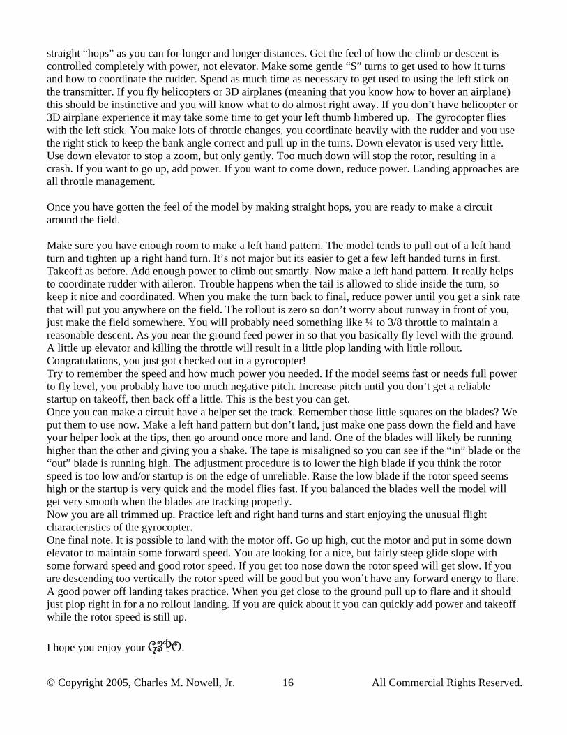
straight “hops” as you can for longer and longer distances. Get the feel of how the climb or descent is controlled completely with power, not elevator. Make some gentle “S” turns to get used to how it turns and how to coordinate the rudder. Spend as much time as necessary to get used to using the left stick on the transmitter. If you fly helicopters or 3D airplanes (meaning that you know how to hover an airplane) this should be instinctive and you will know what to do almost right away. If you don’t have helicopter or 3D airplane experience it may take some time to get your left thumb limbered up. The gyrocopter flies with the left stick. You make lots of throttle changes, you coordinate heavily with the rudder and you use the right stick to keep the bank angle correct and pull up in the turns. Down elevator is used very little. Use down elevator to stop a zoom, but only gently. Too much down will stop the rotor, resulting in a crash. If you want to go up, add power. If you want to come down, reduce power. Landing approaches are all throttle management. Once you have gotten the feel of the model by making straight hops, you are ready to make a circuit around the field. Make sure you have enough room to make a left hand pattern. The model tends to pull out of a left hand turn and tighten up a right hand turn. It’s not major but its easier to get a few left handed turns in first. Takeoff as before. Add enough power to climb out smartly. Now make a left hand pattern. It really helps to coordinate rudder with aileron. Trouble happens when the tail is allowed to slide inside the turn, so keep it nice and coordinated. When you make the turn back to final, reduce power until you get a sink rate that will put you anywhere on the field. The rollout is zero so don’t worry about runway in front of you, just make the field somewhere. You will probably need something like ¼ to 3/8 throttle to maintain a reasonable descent. As you near the ground feed power in so that you basically fly level with the ground. A little up elevator and killing the throttle will result in a little plop landing with little rollout. Congratulations, you just got checked out in a gyrocopter! Try to remember the speed and how much power you needed. If the model seems fast or needs full power to fly level, you probably have too much negative pitch. Increase pitch until you don’t get a reliable startup on takeoff, then back off a little. This is the best you can get. Once you can make a circuit have a helper set the track. Remember those little squares on the blades? We put them to use now. Make a left hand pattern but don’t land, just make one pass down the field and have your helper look at the tips, then go around once more and land. One of the blades will likely be running higher than the other and giving you a shake. The tape is misaligned so you can see if the “in” blade or the “out” blade is running high. The adjustment procedure is to lower the high blade if you think the rotor speed is too low and/or startup is on the edge of unreliable. Raise the low blade if the rotor speed seems high or the startup is very quick and the model flies fast. If you balanced the blades well the model will get very smooth when the blades are tracking properly. Now you are all trimmed up. Practice left and right hand turns and start enjoying the unusual flight characteristics of the gyrocopter. One final note. It is possible to land with the motor off. Go up high, cut the motor and put in some down elevator to maintain some forward speed. You are looking for a nice, but fairly steep glide slope with some forward speed and good rotor speed. If you get too nose down the rotor speed will get slow. If you are descending too vertically the rotor speed will be good but you won’t have any forward energy to flare. A good power off landing takes practice. When you get close to the ground pull up to flare and it should just plop right in for a no rollout landing. If you are quick about it you can quickly add power and takeoff while the rotor speed is still up. I hope you enjoy your G3PO.

1/8 lite ply fuse
112°
7.53 in.
72.0°
4.50 in.
10mm Square Pine/Spruce
10 mm square Pine/Spruce
Landing Gear Lamination
5/32 (0.156) Carbon Fiber Tube, 9" long
Main Gear, 4 laminations of 1/32" ply, Two inner layers have slots, two outer layers,
no slots
2.02 in.
0 1 2 3 4 5Inch
cm0 2 4
6
6 8 10 12
10mm Square Pine/Spruce
1/8 “ Lite Ply fuselage
CopyrightCharles M. Nowell, Jr.
2004, 2005All commercial Rights Reserved
Outer piece, 1/32" Ply, Make 2
Inner piece, 1/32" Ply, Make 2
Optional Downthrust, trim top surface and
uses a spacer on the bottom
surface. ~ 5 degrees

6 mm Depron
6 mm Depronor 3/32 Balsa??
Fin
Rudder
1/32 Ply Control Horn
Goldberg ½A Tailwheel bracket
1/32" Ply Horn Reinforcement
Rudder horn
1/16" Balsa Reinforcement for Depron Fin
01
23
45
Inch cm
02
4
6
68
1012
CopyrightCharles M. Nowell, Jr.
2004, 2005All commercial Rights Reserved
1/16" music wire
Plastic tubing
Use tailboom wrapped with
sandpaper to grove the bottom of the fin
for glueing.
MPI 1.25 “ wheel
Tail Boom
¼ x 1" dowel
Glue into tail boom
#2 screws/washers
Fin outline
1/16" Wheel Collars
Tail Wheel Assembly, Rear View
Tail Wheel Assembly, Side View
Embed in foam safe CA, then apply tape over tubing and around bottom of rudder.

25-¼”
Tail Boom brace, .156 carbon tubing17" long
Bind with thread and CA
CG along this line
8-¼”
1-½”
Ground Reference
96.5°
CopyrightCharles M. Nowell, Jr.
2004, 2005All commercial Rights Reserved
Note: Blades are aerobalsa 1.5" rotor blade airfoils, cut to 16". Tip weights of 1/16' by 3" solder ¼” from
the leading edge, 1" in from the tip.

0.75 in. 0.75 in.
0.50 in.
2.00 in.
0.05 in.
0.05 in.
0.05 in.
Cut this out and glue to22 Gauge “Weldable Steel” from Ace Hardware or Home Depot.The Holes are 3mm, drill them
first. Then cut out the straps with a hacksaw or dremel.
Antirotation Link
Forward
Main Mast
GWS Gearbox
CA Antirotation linkto back of gearbox
Make sure that thus just clears the flybar when tilted fully.
Blade Straps, Make 4 0 1 2 3 4 5Inch
cm0 2 4
6
6 8 10 12
10mm x 25mm 1/32 Plywood
1.5 mm carbon rod X 40 mm
Make this space fits the pin on the swashplate
CA heavily
3/8" – ½”
Make sure these don’t interfere with each other
Roll Pushrod, (other side)
Roll Servo
Pitch Servo
Servo Mounting, Head detailsTO SCALE
CopyrightCharles M. Nowell, Jr.
2004, 2005All commercial Rights Reserved

0 3/4"
0 1/4"
3 "
1/32” Ply
1 1/4"
0 5/
8"
CopyrightCharles M. Nowell, Jr.
2004, 2005All commercial Rights Reserved
Blade Reinforcements
1/8"
1/16" Groove
Spruce or Basswood
Balsa
Spruce or Basswood
Balsa
16"
½”
3mm Holes, Drill AFTER reinforcements are attached.
Leading Edge
Leading Edge Leading Edge Leading EdgeLeading Edge
Leading Edge Leading Edge Leading Edge Leading Edge
Trim off
Trim off
Sand Upper Surface Flat in this shape