g22 2440 001 c51 - nyu.edu · dr. jean-claude franchitti new york university computer science...
TRANSCRIPT

1
1
Software EngineeringG22.2440-001
Session 5 - Main ThemeSoftware Analysis and Design
Dr. Jean-Claude Franchitti
New York UniversityComputer Science Department
Courant Institute of Mathematical Sciences
2
Agenda
• Traditional Data and Process Modeling Approaches
• From Requirements Analysis to Business and Application Models
• Roles of Software Analysis and Design • Object-Oriented Analysis and Design with UML • Selecting and Combining Approaches • Creating a Data Model • Homework #3 • Project #1 (ongoing)• Summary

2
3
Summary of Previous Session
• Review• Architecture-Driven Iterative Process• Project Planning and Estimation• Cooperative Roles of Software Engineering
and Project Management• Summary
4
Part I
Traditional Data and
Process Modeling Approaches

3
5
Key Definitions
• A process model is a formal way of representing how a business operates
• Data flow diagramming shows business processes and the data that flows between them
6
Key Definitions
• Logical process models describe processes without suggesting how they are conducted
• Physical models include information about how the processes are implemented

4
7
Reading a Data Flow Diagram (DFD)
8
DFD Elements

5
9
Structured English
Common Statements Example
Action Statement Profits = Revenues - ExpensesGenerate Inventory - ReportAdd Product record to Product Data Store
If Statement IF Customer Not in Customer Data StoreTHEN Add Customer record to Customer Data StoreELSE Add Current-Sale to Customer’s Total-Sales
Update Customer record in Customer Data Store
For Statement FOR all Customers in Customer Data StoreGenerate a new line in the Customer-ReportAdd Customer’s Total-Sales to Report-Total
Case Statement CASEIf Income < 10,000: Marginal-tax-rate = 10%If Income < 20,000: Marginal-tax-rate = 20%If Income < 30,000: Marginal-tax-rate = 31%If Income < 40,000: Marginal-tax-rate = 35%ELSE Marginal-tax-rate = 38%
ENDCASE
10
Key Definition
• Decomposition is the process of modelingthe system and its components in increasing levels of detail.
• Balancing involves insuring that information presented at one level of a DFD is accurately represented in the next level DFD.

6
11
Context Diagram
• Shows the context into which the business process fits
• Shows the overall business process as just oneprocess
• Shows all the outside entities that receive information from or contribute information to the system
12
Relationship Among DFD levels

7
13
Level 0 Diagram
• Shows all the processes that comprise the overall system
• Shows how information moves from and to each process
• Adds data stores
14
Level 1 Diagrams
• Shows all the processes that comprise a single process on the level 0 diagram
• Shows how information moves from and to each of these processes
• Shows in more detail the content of higher level process
• Level 1 diagrams may not be needed for all level 0 processes

8
15
Level 2 Diagrams
• Shows all processes that comprise a single process on the level 1 diagram
• Shows how information moves from and to each of these processes
• Level 2 diagrams may not be needed for all level 1 processes
• Correctly numbering each process helps the user understand where the process fits into the overall system
16
Data Flow Splits and Joins
• A data flow split shows where a flow is broken into its component parts for use in separate processes
• Data flow splits need not be mutually exclusive nor use all the data from the parent flow
• As we move to lower levels we become more precise about the data flows
• A data flow join shows where components are merged to describe a more comprehensive flow

9
17
Alternative Data Flows
• Where a process can produce different data given different conditions
• We show both data flows and use the process description to explain why they are alternatives
• Tip -- alternative data flows often accompany processes with IF statements
18
Elements of a Use Case
• Trigger -- event that causes the scenario to begin– External trigger– Temporal trigger
• All possible inputs and outputs• Individual steps
– Show sequential order– Show conditional steps

10
19
DFD and Use Cases
• The Data Flow Diagram (DFD) is an essential tool for creating formal descriptions of business processes and data flows.
• Use cases record the input, transformation, and output of business processes.
• Eliciting scenario descriptions and modelling business processes are critically important skills for the systems analyst to master.
20
Process Modeling and DFDs
• Define process modeling• Discuss the purpose of data flow diagrams• Discuss the components of a DFD• Discuss the rules for constructing DFD• Discuss functional decomposition• Create DFD

11
21
Key Ideas
• Process modeling can be used with manual or computerized systems
• Always design processes from the viewpoint of the organization running the system
• Data flow diagrams are a graphical representation of business processes in an information system
• Focus of data flow diagrams is on processes and activities, not data (despite the name)
22
Process Modeling
• Describes business processes or the activities that people do
• Used to document and organize information gathered during systems analysis
• Focus on processes or activities• Start with text description of processes then create
DFDs

12
23
Data Flow Diagrams
• Show the flow of data and logic within a system
• Model:– sources and destinations of data – data inputs and outputs– actions that transform inputs into outputs– data maintained by an information system
24
DFDs
• Primary modeling technique used in traditional systems development
• Start by creating a context DFD – shows boundaries or scope of the system– this is the highest level DFD– have a single process representing the entire
information system and list external entities and data flows

13
25
Types of DFDs
• Logical DFD –– models what the system does
• Physical DFD-– models how it will be done
26
Possibilities
• Current logical• Current physical• New logical• New physical

14
27
Elements of a DFD
• Processes• Data Flows• Data stores• External entities
28
Process
• Any activity that transforms data• Components:
– process identification #– process description label
• Each process performs only one activity

15
29
Data flow
• Traces flow of information throughout the system
• It is data in motion
30
Data store
• Also known as data repository• Is where data is temporarily or permanently
stored or held

16
31
External entity
• External Entity - something or someone that provides data to the system or receives output from the system
• does not perform any system processes• name of entity goes inside the symbol
32PowerPoint Presentation for Dennis & Haley Wixom, Systems Analysis and Design, 2nd EditionCopyright 2003 © John Wiley & Sons, Inc. All rights reserved.6 - 9
Naming and Drawing DFD Elements
Process
Data flow
Data store
Externalentity

17
33
Rules
• Sequence of processes must move from left to right, top to bottom
• Every data flow must begin or end at a process• Avoid black holes• Avoid magic process
34
Business Processes and DFDs
• Business processes cannot be depicted with a single DFD.
• Decomposition is used to depict business processes with a hierarchy of diagrams– Parent and child diagrams
• Balancing is used to ensure accuracy of diagrams at all levels in the hierarchy

18
35
Steps in constructing DFDs
• Create a context DFD• Create DFD fragments• Create level 0 diagram• Create level 1,…,level n diagrams• Validate diagrams created
36
Functional decomposition
• Once a context DFD is created,– then create Level 0 DFD
• Processes from Level 0 DFD are further decomposed– until a sufficient level of detail is reached
• Do it until no sub process can logically be broken down any further
• Lowest level DFD is called a primitive DFD

19
37
Creating a context diagram
• Provides a summary of the overall system• A single process represents the entire
information system• List external entities and data flows• Number for process is 0
38
Creating a level 0 diagram
• Shows major processes that are a part of the overall system
• Shows how the major processes are interrelated by data flows
• Shows external entities and the major processes with which they interact
• Adds data stores

20
39
Creating level 1 diagrams
• Generally, one level 1 diagram is created for every major process on the level 0 diagram
• Shows all the internal processes that comprise a single process on the level 0 diagram
• Shows how information moves from and to each of these processes
• If a parent process is decomposed into, for example, three child processes, these three child processes wholly and completely make up the parent process
40
Validate DFDs
• Look for:– Syntax errors– Semantic errors
• Use:– User walkthroughs– Role-play
• Examine lowest level DFD to ensure consistent decomposition
• Examine names to ensure consistent use of terms

21
41
Describing complex processes
• Techniques used include:– Structured English– Decision Trees– Decision Tables
42
Use Cases & DFDs
• Major use cases become high level processes on Level 0 DFD
• Inputs and outputs become data flows• Number process same as use case number• Change process name into verb phrase• Combine DFD fragments into one diagram• Each step becomes a process for the level 1
DFD

22
43
Key Definitions
• A process model is a formal way of representing how a business operates
• Data flow diagramming shows business processes and the data that flows between them
44
Key Definitions
• Logical process models describe processes without suggesting how they are conducted
• Physical models include information about how the processes are implemented

23
45
Creating Data Flow Diagrams:Integrating Scenario Descriptions
• DFDs generally integrate scenario descriptions• Names of use cases become processes• Names of inputs and outputs become data flows• Combining “small” data inputs and outputs into a
single flow
46
Steps in Building DFDs
• Build the context diagram• Create DFD fragments for each scenario• Organize DFD fragments into level 0• Decompose level 0 DFDs as needed• Validate DFDs with user

24
47
DFD Fragment Tips
• All process names must be verb phrases• Maintain organization’s viewpoint in naming processes• Layouts often place
– processes in the centre– inputs from the left– outputs to the right– stores beneath the processes
48
A DFD Fragment Example

25
49
A Second DFD Fragment Example
50
Level 0 Tips
• Generally move from top to bottom, left to right
• Minimize crossed lines• Iterate as needed
– The DFD is often drawn many times before it is finished, even with very experienced systems analysts

26
51
Tips for Level 1 and Below
• Sources for inputs and outputs listed at higher level• List source and destination of data flows to processes and
stores within each DFD• Depth of DFD depends on overall system complexity
– Two processes generally don’t need lower level– More than seven processes become overly complex and
difficult to read
52
Validating the DFD
• Syntax errors– Assure correct DFD structure
• Semantics errors– Assure accuracy of DFD relative to actual/desired
business processes• User walkthroughs• Role-play processes• Examine lowest level DFDs• Examine names carefully

27
53
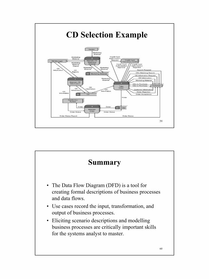
CD Selection Example
54
CD Selection Example

28
55
CD Selection Example
56
CD Selection Example

29
57
CD Selection Example
58
CD Selection Example
30
59
CD Selection Example
60
Summary
• The Data Flow Diagram (DFD) is a tool for creating formal descriptions of business processes and data flows.
• Use cases record the input, transformation, and output of business processes.
• Eliciting scenario descriptions and modelling business processes are critically important skills for the systems analyst to master.

31
61
Part II
From Requirements Analysisto
Business and Analysis Models
(See Session 2 – Handout 8)
62
Gathering Information
32
63
Key Ideas
• The goal of the analysis phase is to truly understand the requirements of the new system and develop a system that addresses them -- or decide a new system isn’t needed.
• The line between systems analysis and systems design is very blurry.
64
Overview
• Interviews• Joint Application Design (JAD)• Questionnaires• Document Analysis• Observation

33
65
Interviews
66
Interviews -- Five Basic Steps
• Selecting Interviewees• Designing Interview Questions• Preparing for the Interview• Conducting the Interview• Post-Interview Follow-up

34
67
Selecting Interviewees
• Based on Information Needed• Often Good to Get Different Perspectives
– Managers– Users– Ideally, All Key Stakeholders
68
Types of Questions
Types of Questions Examples
Closed-Ended Questions * How many telephoneorders are received per day?
* How do customers place orders?* What additional information
would you like the new systemto provide?
Open-Ended Questions * What do you think about the current system?
* What are some of the problemsyou face on a daily basis?
* How do you decide what types ofmarketing campaign to run?
Probing Questions * Why?* Can you give me an example?* Can you explain that in a bit
more detail?

35
69
Designing Interview Questions
• Unstructured interview– Broad, Roughly Defined Information
• Structured interview – More Specific Information
70
Questioning Strategies
High LevelVery General
Medium-LevelModeratelySpecific
Low-LevelVery Specific
TOP DOWN
BOTTOM UP
EXAMPLES?

36
71
Interview Preparation Steps
• Prepare General Interview Plan– List of Question– Anticipated Answers and Follow-Ups
• Confirm Areas of Knowledge• Set Priorities in Case of Time Shortage• Prepare the Interviewee
– Schedule– Inform of Reason for Interview– Inform of Areas of Discussion
72
Conducting the Interview
• Appear professional and unbiased• Record all information• Check on organizational policy regarding tape recording• Be sure you understand all issues and terms• Separate facts from opinions• Give interviewee time to ask questions• Be sure to thank the interviewee• End on time

37
73
Conducting the InterviewPractical Tips
• Don’t Worry, Be Happy• Pay Attention• Summarize Key Points• Be Succinct• Be Honest• Watch Body Language
74
Post-Interview Follow-Up
• Prepare Interview Notes• Prepare Interview Report• Look for Gaps and New Questions

38
75
Interview Report
INTERVIEW REPORT
Interview notes approved by: ____________
Person interviewed ______________Interviewer _______________Date _______________Primary Purpose:
Summary of Interview:
Open Items:
Detailed Notes:
76
JOINT APPLICATION DESIGN (JAD)

39
77
JAD : Introduction
• Invented by IBM late 1970s• Structured Meeting of 10-20 users• ~30 minutes per agenda item• frequent breaks
78
JAD : Overview
• Selecting participants• Designing the session• Preparing for the session• Conducting the session• Follow-Up

40
79
JAD Key Ideas
• Allows project managers, users, and developers to work together
• May reduce scope creep by 50%• Avoids requirements being too specific or
too vague
80
Joint Application Design (JAD) Important Roles
• Facilitator• Scribe

41
81
Joint Application Design (JAD) Setting
• U-Shaped seating• Away from distractions• Whiteboard/flip chart• Prototyping tools• e-JAD
82
JAD Meeting Room
JPEG Figure 5-5 Goes Here

42
83
The JAD Session
• Tend to last 5 to 10 days over a three week period• Prepare questions as with interviews• Formal agenda and ground rules• Facilitator activities
– Keep session on track– Help with technical terms and jargon– Record group input– Help resolve issues
• Post-session follow-up
84
Managing Problems in JAD Sessions
• Reducing domination• Encouraging non-contributors• Side discussions• Agenda merry-go-round• Violent agreement• Unresolved conflict• True conflict• Use humour

43
85
JAD : Summary
• Structured Meeting• Facilitator and scribe + 10-20 users• Attempts to overcome usual problems with
groups• Only one person talks at once• Every opinion is valued
86
QUESTIONNAIRES

44
87
Questionnaire Steps
• Selecting participants– Using samples of the population
• Designing the questionnaire– Careful question selection
• Administering the questionnaire– Working to get good response rate
• Questionnaire follow-up– Send results to participants
88
Good Questionnaire Design
Begin with non-threatening and interesting questions
Group items into logically coherent sections
Do not put important items at the very end of the questionnaire
Do not crowd a page with too many items
Avoid abbreviations
Avoid biased or suggestive items or terms
Number questions to avoid confusion
Pretest the questionnaire to identify confusing questions
Provide anonymity to respondents

45
89
Document Analysis
• Provides clues about existing “as-is” system• Typical documents
– Forms– Reports– Policy manuals
• Look for user additions to forms• Look for unused form elements
90
Observation
• Users/managers often don’t remember everything they do
• Checks validity of information gathered other ways
• Behaviours change when people are watched• Careful not to ignore periodic activities
– Weekly … Monthly … Annual

46
91
Criteria for Selecting the Appropriate Techniques
• Type of information• Depth of information• Breadth of information• Integration of information• User involvement• Cost• Combining techniques
92
Selecting the Appropriate Techniques
Interviews JAD Questionnaires Document ObservationAnalysis
Type of As-Is As-Is As-Is As-Is As-IsInformation Improve. Improve. Improve.
To-Be To-Be
Depth of High High Medium Low LowInformation
Breadth of Low Medium High High LowInformation
Integration Low High Low Low Lowof Info.
User Medium High Low Low LowInvolvement
Cost Medium Low- Low Low Low-Medium Medium

47
93
Gathering Information (Summary)
• Interviews• Joint Application Design (JAD)• Questionnaires• Document Analysis• Observation
94
Part III
Roles of Analysis and Design
Role of analysis with respect to requirements and to design:
http://www.ivarjacobson.com/pub/TechnicalQuestions.html
http://www.ivarjacobson.com/files/AnalysisBasics.htm

48
95
Purpose
• The purposes of Analysis & Design are: – To transform the requirements into a design of
the system-to-be– To evolve a robust architecture for the system– To adapt the design to match the
implementation environment• Designing the system for performance in its run-
time environment
96
Relation to Other
Disciplines
• The Requirements discipline provides the primary input for Analysis and Design
• The Implementation discipline provides the software component organization in the development environment
• The Test discipline tests designed system• The Configuration and Change Management discipline develops and maintains
the supporting artifacts that are used during Analysis and Design• The Project Management discipline plans the project, and each iteration

49
97
Model Characteristics
Requirements Analysis Design Implementation Test• Feature lists• Domain
models• Use cases• Customer
language• External view
• Unambiguous models
• Consistent use cases
• Developer language
• Internal view• Sets solution
architecture• Conceptual • Informal models• Few
abstractions, subsystems, interfaces
• Physical • Technologies
and “-ilities”• Many
abstractions, subsystems, interfaces
• Detailed• Formal
• Implement details (source, scripts, binaries, executables, etc.)
• Distribute executable components across computing nodes
• Unit test
• Test cases, procedures, components
• Integration and system tests
• Feed results back into process
Transform Models
98
Requirements versus Analysis
• Requirements specify the behavior of the largest-grained component: the system– Specifies the behaviors the system provides for and
with the actors– “The system shall…”
• Object-oriented analysis is reduction of a system to a coarse set of discovered objects with responsibilities, so that the set of objects is able to fulfill the behavioral requirements of the user– Analysis limits the effort to objects found in the
domain – otherwise you are doing design

50
99
Analysis Class
• Analysis classes represent an early conceptual model for ‘things in the system which have responsibilities and behavior’
• Class, stereotyped as «boundary», «entity» or «control»– Entity classes
• Long-lived, real-life object or event in the application domain• Data and behavior• Usually persistent (saved in a file or database)
– Boundary classes• Interaction between the system and its actors• At the system boundary
– Control classes• Coordination and sequencing of system behavior• Transactions
Analysis Class
Entity
Control
Boundary
100
Use-Case Realization
Collaboration diagram
Sequence diagram
Class diagram
GrpFile
read( )open( )create( )fillFile( )
rep
Repository
name : char * = 0
readDoc( )readFile( )
(from Persistence)
FileMgr
fetchDoc( )sortByName( )
DocumentList
add( )delete( )
Document
name : intdocid : intnumField : int
get( )open( )close( )read( )sortFileList( )create( )fillDocument( )
fList
1
FileList
add( )delete( )
1
File
read( )
read() fill the code..
Use Cases
Use Case Use-Case Realization
• A use-case realization is a description of how a particular use case is realized within the design model, in terms of collaborating objects
<<trace>>

51
101
Example: Pay Invoice Use Case
• The use case Pay Invoice is used by a Buyer to schedule invoice payments. The Pay Invoice use case then completes the payment on the due date
• Precondition: The Buyer has received the goods or services ordered and at least one invoice from the system. The Buyer now plans to schedule the invoice(s)
• Postcondition: The use-case ends when the invoice has been paid or the invoice payment was canceled and no money was transferred
102
Pay Invoice Use Case: Flow of Events• Basic path
1. The buyer invokes the use case by beginning to browse the invoices received by the system. The system checks that the content of each invoice is consistent with the order confirmations received earlier (as part of the Confirm Order use case) and somehow indicates this to the buyer. The order confirmation describes which items will be delivered, when, where, and at what price.
2. The buyer decides to schedule an invoice for payment by the bank, and the system generates a payment request to transfer money to the seller’s account. Note that a buyer may not schedule the same invoice for payment twice.
3. Later, if there is enough money in the buyer’s account, a payment transaction is made on the scheduled date. During the transaction, money is transferred from the buyer’s account to the seller’s account, as described by the abstract use case Perform Transactions (which is used by Pay Invoice). The buyer and the seller are notified of the result of the transaction. The bank collects a fee for the transaction, which is withdrawn from the buyer’s account by the system.
4. The use-case instance terminates− (Alternative Paths not included here)

52
103
Analysis Class Diagram Realizing a Pay Invoice Use Case
Order Confirmation
Buyer Payment Request UI
Order Handler
Invoice
Payment Scheduler Payment Request
104
Collaboration Diagram Realizing a Pay Invoice Use Case
Scott : Buyer : Payment Request UI
: Order Handler
: Payment Scheduler : Payment Request
: Order Confirmation
: Invoice
1: Browse Invoice
6: Schedule Invoice for Payment
2: Browse
9: setStatus(scheduled)
3: Check Invoice
7: Schedule payment
4: Get
5: Get
8: New

53
105
Iteration
Use Case A
Use Case ARealization
Iteration n
Use Case B
Use Case BRealization
Iteration n+1
Use Case C
Use Case CRealization
Iteration n+2
• Iteratively develop the system, one use case at a time
• Early iterations− Architecturally
significant use cases
− High risk use cases
− High priority use cases
time
106
Analysis versus Design
• Analysis– Focus on
understanding the problem
– Idealized design– Behavior– Functional structure– Functional
requirements– A small model
• Design– Focus on
understanding the solution
– Operations and attributes
– Performance– Close to real code– Object lifecycles– Non-functional
requirements– A large model

54
107
Analysis versus Design• Analysis
– Understand the problem and begin to develop a visual model of what you are trying to build• Independent of implementation and technology
concerns– Translate the functional requirements into
software concepts• Get a rough cut at the objects that comprise the
system– Focus on behavior– Focus on structure: coupling/separating concerns
• Design– Refine the model into a form that will allow a
seamless transition into implementation
108
Analysis versus Design• “If you tried to manage all of the analysis and design
issues in one go, your brain would explode on all but the most trivial developments.”
• Mental switch of focus– Analysis: problem domain
• I do care about what the system has to do• I don’t care (as much) about memory, persistence, databases,
languages, etc.– Design: solution domain
• I do care about memory, persistence, databases,etc.• I don’t care (as much) about understanding the problem
• In practice, Analysis and Design are closely related and often iterative– To understand a problem, produce a solution– The “as much” above is a balance of focus

55
109
Not Top-Down or Bottom-Up – It is Middle-In/Out
• The use cases define a middle level• At the middle level, identify analysis
classes that collaborate to realize the use cases
• From the middle level, move up and down– Up: Defining subsystems– Down: Defining design classes
• Understanding and solving the problem is iterative– Middle-to-Top, Top-to-Middle,
Middle-to-Bottom, and Bottom-to-Middle
Subsystems
Analysis Classes
Design Classes
Use Cases
110
What is Architecture?
• Software architecture encompasses the set of significant decisions about the organization of a software system– Selection of the structural elements and their
interfaces by which a system is composed– Behavior as specified in collaborations among those
elements– Composition of these structural and behavioral
elements into larger systems– Architectural style or pattern that guides this
organization
• Architecture = Elements + Form + Rationale

56
111
Architecture Constrains Design Which Constrains Implementation
• Architecture involves a set of strategic design decisions, rules, or patterns that constrain design and implementation
CODE
architecturedesign
implementation
Incrementally assess and reduce the space of solution options
Architecture decisions are the most fundamental decisions
• Changing them will have significant ripple effects
112
“4+1 View” Model of Software Architecture
Logical View
FunctionalityStructure
Implementation View
Software management
Process View
Performance, scalability, throughput
Deployment View
System topology,delivery, installation,
communication
Use Case ViewFunctionality
UnderstandabilityUsability
• Each view covers particular concerns, omitting elements not relevant to that concern
• Views are “slices” of the overall system model

57
113
Analysis and Design Workflow
114
Analysis and Design Roles, Activities, and Artifacts

58
115
Define the Architecture
116
Grow the Design

59
117
Designer Role
• The designer role defines the responsibilities, operations, attributes, and relationships of one or several classes, and determines how they will be adjusted to the implementation environment
• Skills and Knowledge– Use-case modeling techniques – System requirements – Software design techniques,
including object-oriented analysis and design techniques, and the Unified Modeling Language
– Technologies with which the system will be implemented
118
Part IV
Object-Oriented Modeling with UML

60
119
Session Objectives
Key termsUse CaseObjectObject classStateBehaviorOperationEncapsulationConstructor OperationQuery OperationUpdate OperationAssociationMultiplicity
Abstract ClassConcrete ClassClass-Scope attributeAbstract operationMethodPolymorphismOverridingAggregationCompositionEventState transitionSequence diagram
120
Session Objectives
Discuss the concepts and principles underlying the object-oriented approachDescribe the activities in the different phases of the object-oriented development life cycleState the advantages of object-oriented modeling versus traditional systems development approachesLearn to develop requirements models using use-case diagramsLearn to use class diagrams to develop object models of the problem domainLearn to develop dynamic models using state, interaction and activity diagramsModel real-world applications using UML diagrams

61
121
Introduction
• Object-Oriented systems development life cycle
– Process of progressively developing representation of a system component (or object) through the phases of analysis, design and implementation
– The model is abstract in the early stages– As the model evolves, it becomes more and
more detailed
122
The Object-Oriented Systems Development Life Cycle
• Analysis Phase– Model of the real-world application is developed
showing its important properties– Model specifies the functional behavior of the system
independent of implementation details• Design Phase
– Analysis model is refined and adapted to the environment
– Can be separated into two stages• System design
– Concerned with overall system architecture• Object design
– Implementation details are added to system design

62
123
The Object-Oriented Systems Development Life Cycle
• Implementation Phase– Design is implemented using a programming
language or database management system
124
The Object-Oriented Systems Development Life Cycle
• Deliverables and Outcomes1. The ability to tackle more challenging problem domains2. Improved communication among users, analysts, designers and
programmers3. Increased consistency among analysis, design and programming
activities4. Explicit representation of commonality among system
components5. Reusability of analysis, design and programming results6. Increased consistency among the models developed during
object-oriented analysis, design, and programming

63
125
The Unified Modeling Language (UML)
• A notation that allows the modeler to specify, visualize and construct the artifacts of software systems, as well as business models
• Techniques and notations– Use cases– Class diagrams– State diagrams– Sequence diagrams– Activity diagrams
126
Use-Case Modeling
• Applied to analyze functional requirements of the system
• Performed during the analysis phase to help developers understand functional requirements of the system without regard for implementation details
• Use Case– A complete sequence of related actions initiated by an
actor• Actor
– An external entity that interacts with the system

64
127
Use-case diagram for a university registration system
128
Use-Case Modeling
• Developing Use-Case Diagrams – Use cases are always initiated by an actor– Use cases represent complete functionality of the
system• Relationships Between Use Cases
– Use cases may participate in relationships with other use-cases
– Two types• Extends
– Adds new behaviors or actions to a use case• Include
– One use case references another use case

65
129
Object ModelingClass Diagrams
• Object– An entity that has a well-defined role in the application
domain, and has state, behavior, and identity• State
– A condition that encompasses an object’s properties and the values those properties have
• Behavior– A manner that represents how an object acts and reacts
• Object Class– A set of objects that share a common structure and a
common behavior
130
Object ModelingClass Diagrams
• Class Diagram– Class is represented as a rectangle with three
compartments– Objects can participate in relationships with
objects of the same class

66
131
Object ModelingObject Diagrams
• Object Diagram– A graph of instances that are compatible with a given
class diagram; also called an instance diagram– Object is represented as a rectangle with two
compartments• Operation
– A function or service that is provided by all the instances of a class
• Encapsulation– The technique of hiding the internal implementation
details of an object from its external view
132
Object ModelingObject Diagrams
• Types of Operations– Query
• An operation that accesses the state of an object but does not alter the state
– Update• An operation that alters the state of an object
– Scope• An operation that applies to a class rather than an object
instance– Constructor
• An operation that creates a new instance of a class

67
133
UML class and object diagrams(a) Class diagram showing two classes(b) Object diagram with two instances
134
Representing Associations
• Association– A relationship between object classes– Degree may be unary, binary, ternary or higher– Depicted as a solid line between participating classes
• Association Role– The end of an association where it connects to a class– Each role has multiplicity, which indicates how many
objects participate in a given association relationship

68
135
Representing Association Classes
• Association Class– An association that has attributes or operations
of its own, or that participates in relationships with other classes
• Similar to an associative entity in ER modeling
136
Representing Derived Attributes, Derived Associations and Derived Roles
• Derived attributes, associations and roles can be computed from other attributes, associations or roles
• Shown by placing a slash (/) before the name of the element
69
137
Representing Generalization
• Generalization– Abstraction of common features among multiple
classes, as well as their relationships, into a more general class
• Subclass– A class that has been generalized
• Superclass– A class that is composed of several generalized
subclasses
138
Representing Generalization
• Discriminator– Shows which property of an object class is being
abstracted by a generalization relationship• Inheritance
– A property that a subclass inherits the features from its superclass
• Abstract Class– A class that has no direct instances, but whose
descendents may have direct instances• Concrete Class
– A class that can have direct instances

70
139
Representing Generalization
• Semantic Constraints among Subclasses– Overlapping
• A descendant may be descended from more than one of the subclasses
– Disjoint• A descendant may not be descended from more than one of the
subclasses– Complete
• All subclasses have been specified. No additional subclasses are expected
– Incomplete• Some subclasses have been specified, but the list is known to
be incomplete
140
Representing Generalization
• Class-scope Attribute– An attribute of a class which specifies a value common
to an entire class, rather than a specific value for an instance.
• Abstract Operation– Defines the form or protocol of an operation but not its
implementation• Method
– The implementation of an operation• Polymorphism
– The same operation may apply to two or more classes in different ways

71
141
Interpreting Inheritance and Overriding
• Overriding– Process of replacing a method inherited from a superclass by a
more specific implementation of that method in a subclass– Three Types
• Overriding for Extension– Operation inherited by a subclass from its superclass is extended
by adding some behavior• Overriding for restriction
– The protocol of the new operation in the subclass is restricted• Overriding for optimization
– The new operation is implemented with improved code by exploiting the restrictions imposed by a subclass
142
Representing Multiple Inheritance
• Multiple Classification– An object is an instance of more than one class– Use is discouraged and not supported by UML
semantics• Multiple Inheritance
– Allows a class to inherit features from more than one superclass

72
143
Representing Aggregation
• Aggregation– A part-of relationship between a component
object and an aggregate object– Example: Personal computer
• Composed of CPU, Monitor, Keyboard, etc
144
Dynamic Modeling:State Diagrams
• State– A condition during the life of an object during which
it satisfies some conditions, performs some actions or waits for some events
– Shown as a rectangle with rounded corners• State Transition
– The changes in the attribute of an object or in the links an object has with other objects
– Shown as a solid arrow– Diagrammed with a guard condition and action
• Event– Something that takes place at a certain point in time

73
145
Dynamic Modeling:Sequence Diagrams
• Sequence Diagram– A depiction of the interaction among objects during
certain periods of time
• Activation– The time period during which an object performs an
operation
• Messages– Means by which objects communicate with each
other
146
Dynamic ModelingSequence Diagrams
• Synchronous Message– A type of message in which the caller has to
wait for the receiving object to finish executing the called operation before it can resume execution itself
• Simple Message– A message that transfers control from the
sender to the recipient without describing the details of the communication
74
147
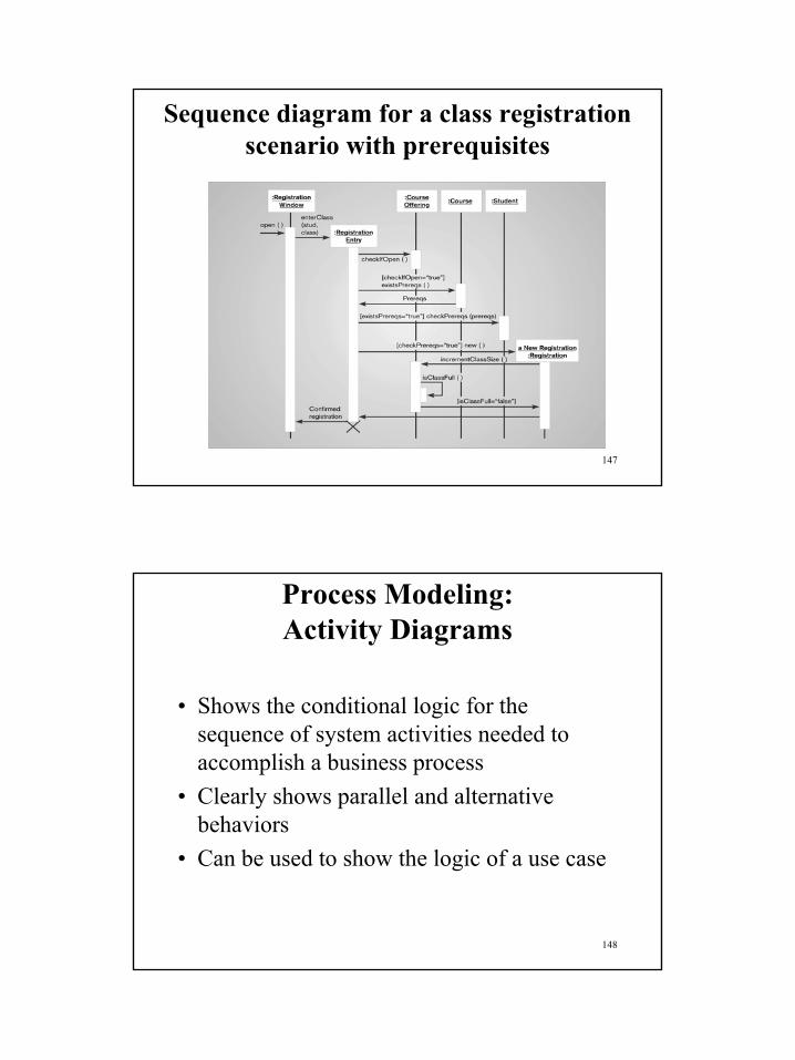
Sequence diagram for a class registration scenario with prerequisites
148
Process Modeling:Activity Diagrams
• Shows the conditional logic for the sequence of system activities needed to accomplish a business process
• Clearly shows parallel and alternative behaviors
• Can be used to show the logic of a use case

75
149
Analysis Versus Design
• Start with existing set of analysis model• Progressively add technical details• Design model must be more detailed than analysis
model• Component Diagram
– A diagram that shows the software components or modules and their dependencies
• Deployment Diagram– A diagram that shows how the software components,
process and objects are deployed into the physical architecture of the system
150
Summary
• Object-Oriented modeling approach– Benefits– Unified Modeling Language
• Use cases• Class diagrams• State diagrams• Sequence diagrams• Activity Diagrams
• Use-case modeling

76
151
Summary
• Object Modeling: Class Diagrams– Associations– Generalizations– Inheritance and Overriding– Aggregation
• Dynamic Modeling: State Diagrams• Dynamic Modeling: Sequence Diagrams• Analysis Versus Design
152
Part V
Selecting and Combining Approaches

77
153
Key Definitions
• The purpose of the design phase is to translate the “what” of the analysis phase to the “how” of new system development
• Logical DFDs and ERDs are converted into physical DFDsand ERDs
• Structured English is turned into pseudocode and CASE repositories are expanded
154
Design Strategies
• Custom development (build from scratch)• Purchase and customise• Outsource development

78
155
Classical Mistakes
• Reducing design time• Feature creep• Silver bullet syndrome• Switching tools in mid-project
156
Design Strategies

79
157
Custom Development
Pros Cons
Allows flexibilityand creativity
Builds technical skills and functional knowledge in-house
Requires significant time and effort
May exacerbate existing backlogs
May require missing skills
Often costs more
Often takes more calendar time
Risk of project failure
158
Packaged Software
• Include small single-function tools• All-encompassing enterprise resource planning (ERP)
systems• Rarely a perfect fit with business needs• May allow for customization
– Manipulation of system parameters– Changing way features work– Synchronizing with other application interfaces

80
159
Systems Integration
• Building systems by combining packages, legacy systems, and custom pieces
• Integrating data is the key
160
Outsourcing
• Hiring an external vendor, developer, or service provider
• May reduce costs or add value• Risks include possibly
– Losing confidential information– Losing control over future development– Losing learning opportunities

81
161
Outsourcing Contracts
• Time and arrangements• Fixed-price• Value-added
162
Outsourcing Guidelines
• Keep lines of communication open• Define and stabilize requirements before signing
the contract• View the relationship as a partnership• Select vendor, developer, or provider carefully• Assign someone to manage the relationship• Don’t outsource what you don’t understand• Emphasize flexible requirements

82
163
Selecting a Design Strategy
• Consider each of the following:– Business need– In-house experience– Project skills– Project management– Time frame
164
Developing The Actual Design

83
165
Developing an Alternative Matrix
• What tools and technologies are needed for a custom development project?
• What vendors make products that address the project needs?
• What service providers would be able to build this application if outsourced?
166
Requests for Proposals (RFP)
• Solicits proposals from vendor, developer, or service providers
• Explains the system and criteria for selecting among applicants
• Request for Information (RFI) -- a shorter version

84
167
Request for Proposal Contents
• Description of desired system• Special technical needs or circumstances• Evaluation criteria• Instructions on how to respond• Desired schedule• Other information that will help the submitter to make a
more complete or accurate proposal
168
Moving From Logical To Physical Models

85
169
Key Definition
• In contrast to the logical DFD and ERD which shows the business view of the new system, the physical DFD and ERD will show the implementation details and how the system will work.
170
The Physical DFD
• Contains the same components as the logical DFD• The same rules pertaining to balance and
decomposition apply• Contains additional details describing how the
system will be built

86
171
Steps to Create the Physical DFD
• Add implementation references• Draw a human-machine boundary• Add system related data stores, data flows and
processes• Update data elements in the data flows• Update the metadata in the CASE repository
172
Contrasting Logical and Physical DFDs

87
173
The Physical ERD
• Contains the same components as the logical ERD
• The same rules pertaining to cardinality and modality apply
• Contains additional details describing how the data will be stored, in a file or database table
174
Steps to Create the Physical ERD

88
175
Summary
• The design phase is where the blueprint of the system is developed
• The Project team considers and selects among– custom application development, – buying a package and customizing it, and– outsourcing.
• Physical DFDs and ERDs add details about the implementation of the system to the “business view”
176
Use Case Design

89
177
Grow the Design
Detailed design activities (class design and use-case design) are tightly bound and alternate between one another
178
Review: Use-Case Analysis - Steps
• Supplement the Use-Case Description• For each use-case realization
– Find classes from Use-Case Behavior– Distribute Use-Case Behavior to Classes
• For each resulting analysis class– Describe responsibilities– Describe attributes and associations– Qualify architectural analysis mechanisms
• Unify analysis classes• Review

90
179
Analysis Results• Architecture
– Packages organized into Layers – focused on upper layers– Analysis mechanisms– Key abstractions (classes)
• Classes– Classes named to reflect their roles and responsibilities– Classes defined
• Responsibilities, Attributes• Associations• Classes are internally cohesive
– Classes assigned to packages• Closely related classes are in the same packages• Packages are loosely coupled
• Use-case realizations– All required functionality is realized – all flows are realized– Each class has the attributes and responsibilities it needs to
carry out its assigned responsibility
180
Analysis versus Design
• Analysis– Focus on
understanding the problem
– Idealized design– Behavior– Functional
structure– Functional
requirements– A small model
• Design– Focus on
understanding the solution
– Operations and attributes
– Performance– Close to real code– Object lifecycles– Non-functional
requirements– A large model

91
181
Step into Design
• Next steps are to refine the analysis model into a design model
• Two perspectives for further decomposition– Architecture: further detailing of parts and
their relationships• Packages Subsystems• Analysis mechanisms Design mechanisms
– Class: further detailing of the parts• Analysis classes Design classes, components,
and interfaces• A third perspective assures integration
(“Re-composition”)– Use-case realization -- Design
182
Purpose of “Grow the Design” Workflow
• Provide the natural transition from analysisactivities to design activities, identifying: – appropriate design elements from analysis elements – appropriate design mechanisms from related analysis
mechanisms
• Maintain the consistency and integrity of the architecture, ensuring that:– new design elements identified for the current iteration
are integrated with pre-existing design elements. – maximal re-use of available components and design
elements is achieved as early as possible in the design effort.

92
183
Context of Use-Case Design• Based on prior analysis and design, we have
– An initial architecture design– Defined major elements of our system (subsystems, their
interfaces, the design classes, the processes, and threads) and their relationships
– An understanding of how processes map to system hardware• Now, in use-case design, we concentrate on how a use case is
implemented and make sure there is consistency from beginning to end
• Use-case design is where the design elements meet the architectural mechanisms– The use-case realization from analysis is refined to included the
design elements, using the patterns of interaction defined for the architectural mechanisms
184
Background of Use-Case Design
• Use-Case Design is a cross-checking, consistency-imposing activity– Focus on a “use-case thread” to make sure everything
still fits together– Continually review the interaction diagrams, looking
for• inconsistencies• missing information• opportunities for reuse• etc.
– Make sure we have operations for the whole path of the flow of events

93
185
Verifying for Consistency
• For each use case, across all use cases, verify that– All the necessary behavior to support a use-case
implementation has been distributed among the appropriate participating classes
– The use-case flows naturally over the participating design elements
– All associations between design elements (classes or subsystems) needed for the use case realizations have been defined
– All the attributes needed for the use-cases have been defined• Refine the analysis-level use cases to included the
defined design model elements (which are the design classes and subsystems that the analysis classes have “morphed into”)
• Incorporate applicable architectural design mechanisms
186
Purpose of Use-Case Design
• To refine use-case realizations in terms of interactions.
• To refine requirements on the operations of design classes.
• To refine requirements on the operations of subsystems and/or their interfaces.
• To refine requirements on the operations of capsules

94
187
Use-Case Design
Use-CaseDesign
SupplementarySpecification
Use-Case Realization- Analysis
Use-Case Realization – Design(Refined)
Use-Case Specifications
DesignClasses
Design Subsystemsand Interfaces
Multiple design teams, each with a different focus
• Class diagrams• Sequence diagrams• Refined flow-of-
events descriptions
188
Use-Case Design Steps
• Describe interaction between design objects• Simplify sequence diagrams using subsystems• Describe persistence related behavior
– Read, write, delete persistent objects– Model transactions– Handle error conditions– Handle concurrency control
• Refine the flow of events description• Unify classes and subsystems• Evaluate your results

95
189
Use-Case Design Steps
• Describe interaction between design objects• Simplify sequence diagrams using
subsystems• Describe persistence related behavior
– Read, write, delete persistent objects– Model transactions– Handle error conditions– Handle concurrency control
• Refine the flow of events description• Unify classes and subsystems• Evaluate your results
Next
190
Review: Use-Case Realization
user : »ç¿ëÀÚ
mainWnd : MainWnd
fileMgr : FileMgr
repository : Repositorydocument : Document
gFile : GrpFile
9: sortByName ( )
L1: Doc view request ( )
2: fetchDoc( )
5: readDoc ( )
7: readFile ( )
3: create ( )
6: fillDocument ( )
4: create ( )
8: fillFile ( )
Collaboration diagram
usermainWnd fileMgr :
FileMgrrepositorydocument :
DocumentgFile
1: Doc view request ( )
2: fetchDoc( )
3: create ( )
4: create ( )
5: readDoc ( )
6: fillDocument ( )
7: readFile ( )
8: fillFile ( )
9: sortByName ( )
ƯÁ¤¹®¼-¿¡ ´ëÇÑ º¸±â¸¦ »ç¿ëÀÚ°¡ ¿äûÇÑ´Ù.
È-ÀÏ°ü¸®ÀÚ´Â Àоî¿Â ¹®¼-ÀÇ Á¤º¸¸¦ ÇØ´ç ¹®¼- °´Ã¼¿¡ ¼³Á¤À» ¿äûÇÑ´Ù.
È-¸é °´Ã¼´Â ÀоîµéÀÎ °´Ã¼µé¿¡ ´ëÇØ À̸§º°·Î Á¤·ÄÀ» ½ÃÄÑ È-¸é¿¡ º¸¿©ÁØ´Ù.
Sequence diagram
Class diagram
GrpFile
read( )open( )create( )fillFile( )
rep
Repository
name : char * = 0
readDoc( )readFile( )
(from Persistence)
FileMgr
fetchDoc( )sortByName( )
DocumentList
add( )delete( )
Document
name : intdocid : intnumField : int
get( )open( )close( )read( )sortFileList( )create( )fillDocument( )
fList
1
FileList
add( )delete( )
1
File
read( )
read() fill the code..
Use Cases
Use Case Use-Case Realization
• A use-case realization is a description of how a particular use case is realized within the design model, in terms of collaborating objects
<<trace>>

96
191
Review: From Analysis Classes to Design Elements
• Analysis classes will seldom retain their same structure through design– They may be expanded, collapsed, combined, or even
deleted in design
Analysis Classes Design ElementsMany-to-Many
Mapping
192
Use-Case Realization Refinement• Identify participating objects• Allocate responsibilities amongst objects• Model messages between objects• Describe processing resulting from messages• Model associated class relationships• In essence, re-draw the analysis realizations, now
using the design elements the analysis models were refined into, making sure that the allocation of responsibility is still accurate
Sequence diagramsClass diagrams

97
193
Use-Case Realization Refinement Steps
• Identify each object that participates in the flow of the use-case
• Represent each participating object in a sequence diagram
• Incrementally incorporate applicable architectural mechanisms
194
Use-Case Design Steps
• Describe interaction between design objects• Simplify sequence diagrams using
subsystems• Describe persistence related behavior
– Read, write, delete persistent objects– Model transactions– Handle error conditions– Handle concurrency control
• Refine the flow of events description• Unify classes and subsystems• Evaluate your results
Next

98
195
With Subsystems and Architectural Mechanisms
• Look at the interaction diagrams• For each class that has been refined into a subsystem,
replace the class with the associated subsystem interface– Any interactions that describe HOW the subsystem
should implement the service should be deferred until subsystem design
• Incrementally incorporate any applicable architectural mechanisms– Use the patterns of behavior defined for the mechanisms– May include the introduction of new design elements and
messages• Update the dynamic and static parts (sequence diagrams
and view of participating classes diagram)
196
Representing Subsystems on a Sequence Diagram
• Interfaces– Represents any model element that realizes the
interface– No message should be drawn from the interface
• Proxy class– Represents a specific subsystem– Messages can be drawn from the proxy
Proxy
OK

99
197
Example : Incorporating Subsystem Interfaces
BillingSystem
+ submitBill(forStudent : Student, forTuition : double)
<<subsystem proxy>>
IBill ingSys tem
+ submitBill(forTuition : Double, forStudent : Student)
(from External System Interfaces)
<<Interface>>
ICourseCatalogSystem
+ getCourseOfferings(forSemester : Semester) : CourseOfferingList+ init ialize()
(from External System Interfaces)
<<Interface>>
CourseCatalogSystem
+ getCourseOfferings(forSemester : Semester) : CourseOfferingList+ initialize()
(f rom CourseCatalogSystem)
<<subsystem proxy>>
BillingSystem
//submit bill()
CourseCatalogSystem
//get course offerings()
Analysis Classes Design Elements
198
Example: Incorporating Subsystem Interfaces (Before)
: Student :
RegisterForCoursesForm :
RegistrationController : Schedule : Student
: Course Catalog :
CourseCatalogSystem
A list of the available course offerings for this semester are displayed
Student wishes to create a new schedule
1. // create schedule( )
1.2. // display course offerings( )
1.1. // get course offerings( )
1.1.1. // get course offerings(forSemester)
1.3. // display blank schedule( )
At this, point the Submit Schedule subflow is executed.
Sequence Diagram: Register for Courses / Register for Courses - Basic Flow (Submit Schedule)
2. // select 4 primary and 2 alternate offerings( )
2.1. // create schedule with offerings( )2.1.1. // create with offerings( )
A blank schedule is displayed for the students to select offerings
2.1.2. // add schedule(Schedule)
1.1.1.1. // get course offerings( )
Replace with subsystem interface

100
199
: Student
: RegisterForCoursesForm : RegistrationController : Schedule : Student. : ICourseCata...
A list of the available course offerings for this semester are displayed
Student wishes to create a new schedule
At this, point the Submit Schedule subflow is executed.
A blank schedule is displayed for the students to select offerings
This flow is inserted after the Register for Courses - Basic FlowSequence Diagram: Register for Courses / Register for Courses - Basic Flow
Sequence Diagram: University Artifacts / Use of Schedule Offering Info
1. createSchedule( )
1.2. displayCourseOfferings( )
1.3. displayBlankSchedule( )
2. select 4 primary and 2 alternate()( )
1.1. // get course offerings( )
2.1. c reate schedule with offerings(CourseOfferingList, CourseOfferingList)
2.1.1. new(forSemester : Semester, withPrimaryOfferings : CourseOfferingList, withAlternateOfferings : CourseOfferingLi...
2.1.2. addSchedule(theSchedule : Schedule)
1.1.1. getCourseOfferings(Semester)
Replaced with subsystem interface
Example: Incorporating Subsystem Interfaces (After)
200
Encapsulating Subsystem Interactions
• Interactions can be described at several levels of abstraction
• Subsystem internal interactions can be described in their own interaction diagrams
Coarse-grained interaction between
subsystems
Fine-grained interaction within
subsystems

101
201
When to Encapsulate Sub-Flows in a Subsystem
• Encapsulate a sub-flow when it:– occurs in multiple use-case realizations– has reuse potential– is complex and easily encapsulated– is the responsibility of one person/team– produces a well-defined result– is encapsulated within a single Implementation Model
component
• Make sure that what you are abstracting is worth abstracting
202
Guidelines: Encapsulating Subsystem Interactions
• Subsystems should be represented by their interfaces on interaction diagrams
• Messages to subsystems are modeled as messages to the subsystem interface
• Messages to subsystems correspond to operations on the subsystem interface
• Interactions within subsystems are modeled in subsystem design
:InterfaceA
InterfaceAop1()
op1()

102
203
Advantages of Encapsulating Subsystem Interactions
• Use-case realizations– Are less cluttered– Can be created before the internal designs of
subsystems are created• parallel development
– Are more generic and easier to change• subsystems can be substituted
204
Parallel Subsystem Development
• Concentrate on requirements that affect subsystem interfaces
• Outline required interfaces• Model messages that cross subsystem boundaries• Draw interaction diagrams in terms of subsystem
interfaces fore each use-case• Refine the interfaces needed to provide messages• Develop each subsystem in parallel
Use subsystem interfaces as project synchronization points

103
205
Use-Case Design Steps
• Describe interaction between design objects• Simplify sequence diagrams using
subsystems• Describe persistence related behavior
– Model transactions– Read, write, delete persistent objects– Handle error conditions– Handle concurrency control
• Refine the flow of events description• Unify classes and subsystems• Evaluate your results
Next
206
Modeling Transactions
• What is a Transaction?– Atomic operation invocations– “All or nothing”– Assure consistency in changes
• Modeling options– Textually (scripts)– Explicit messages
• Error conditions– Rollback– Failure modes– May require separate interaction diagrams

104
207
Use-Case Design Steps
• Describe interaction between design objects• Simplify sequence diagrams using
subsystems• Describe persistence related behavior
– Model transactions– Read, write, delete persistent objects– Handle error conditions– Handle concurrency control
• Refine the flow of events description• Unify classes and subsystems• Evaluate your results
Next
208
Detailed Flow of Event Description Options
• Annotate the interaction diagrams to clarify behavior– Timing– Conditional behavior– Clarification or constraint on operation
behavior– Control flow (decision steps, looping,
branching)• Use UML notes or use free-form text

105
209
Use-Case Design Steps
• Describe interaction between design objects• Simplify sequence diagrams using
subsystems• Describe persistence related behavior
– Model transactions– Read, write, delete persistent objects– Handle error conditions– Handle concurrency control
• Refine the flow of events description• Unify classes and subsystems• Evaluate your results
Next
210
Design Model Unification Considerations
• Model element names should describe their function– Avoid similar names– Avoid synonyms
• Merge similar model elements• Use inheritance to abstract model elements• Keep model elements and flows of events
consistent– When updating a model element, also update the
affected use-case realizations

106
211
Use-Case Design Steps
• Describe interaction between design objects• Simplify sequence diagrams using
subsystems• Describe persistence related behavior
– Model transactions– Read, write, delete persistent objects– Handle error conditions– Handle concurrency control
• Refine the flow of events description• Unify classes and subsystems• Evaluate your results
Next
212
Checkpoints: Use-Case Design
• Is package/subsystem partitioning logical and consistent?
• Are the names of the packages/subsystems descriptive?• Do the public package classes and subsystem interfaces
provide a single, logically consistent set of services?• Do the package/subsystem dependencies correspond to
the relationships between the contained classes?• Do the classes contained in a package belong there
according to the criteria for the package division?• Are there classes or collaborations of classes which can
be separated into an independent package/subsystem?

107
213
Checkpoints: Use-Case Design
• Have all the main and/or sub-flows for this development iteration been handled?
• Has all behavior been distributed among the participating design elements?
• Has behavior been distributed to the right design elements?
• If there are several interaction diagrams for the use-case realization, is it easy to understand which diagrams relate to which flow of events?
214
Part VI
Creating a Data Model

108
215
Key Definitions
• A data model shows the people, places and things of interest to an organization and the relationships among them.
• The logical data model shows the organization of data without indicating how it is stored, created, or manipulated.
216
Key Definitions
• A physical data model shows how the data will actually be stored in the database.
• Normalization is the process analysts use to check for data redundancy.

109
217
The Entity-Relation Diagram (ERD)
218
What Is an ERD?
• A picture showing the information created, stored, and used by a business system.
• Entities generally represent people, places, and things of interest to the organization.
• Lines between entities show relationships between entities.
110
219
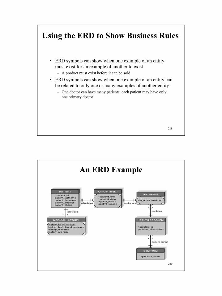
Using the ERD to Show Business Rules
• ERD symbols can show when one example of an entity must exist for an example of another to exist– A product must exist before it can be sold
• ERD symbols can show when one example of an entity can be related to only one or many examples of another entity– One doctor can have many patients, each patient may have only
one primary doctor
220
An ERD Example

111
221
ERD Elements
222
Entities and Instances

112
223
Case Repository Entry for Patient Entity
224
Attributes
• Information captured about an entity• Only those used by the organization should be
included in the model• Attribute names are nouns• Sometimes entity name is added at the beginning
of the attribute name

113
225
Identifiers
• The identifier consists of one or more attributes that can uniquely identify each instance of the entity.
226
Identifier Types

114
227
Case Repository Entry for Patient_SSN Attribute
228
Relationships
• Associations between entities• Connected by a line• Given active verb names
– One verb can describe relationship in both directions
– Two verbs can describe each relationship

115
229
Cardinality
• Cardinality refers to the number of times instances in one entity can be related to instances in another entity– One instance in an entity refers to one and only one instance in the
related entity (1:1)– One instance in an entity refers to one or more instances in the
related entity (1:M)– One or more instances in an entity refer to one or more instances in
the related entity (M:M)
230
Modality
• Modality refers to the minimum number of times that an instance in one entity can be related to an instance in another entity– One means that an instance in the related entity must exist for an
instance in another entity to be valid – Zero means that no instance in the related entity is necessary for an
instance in another entity to be valid

116
231
Case Repository Entry for a Relationship
232
Metadata
• Information about components of the model• Metadata is stored in the CASE repository so it
can be shared by developers and users throughout the SDLC

117
233
Metadata Examples
An Entity An Attribute A Relationshipcan be can be can be described by: described by: described by:
Name Name Verb phraseDefinition Description DefinitionNotes Alias Cardinality
Acceptable Values ModalityFormat NotesNotes
234
Creating An Entity-Relationship Diagram

118
235
ERD Basics
• Drawing the ERD is an iterative process of trial and revision
• ERDs can become quite complex
236
Steps in Building ERDs
• Identify the entities• Add appropriate attributes for each entity• Draw the relationships that connect
associated entities

119
237
ERD Building Tips
• Data stores of the DFD should correspond to entities
• Only include entities with more than one instance of information
• Don’t include entities associated with implementation of the system, not the system itself
238
An ERD Example: The CD Entity

120
239
An ERD Example: The CD’s Relationships
240
An ERD Example: CD’s Relationships Expanded

121
241
Advanced Syntax
242
Special Types of Entities
• Intersection entities are created to store information about two entities sharing an M:M relationship
• Independent entities can exist without the help of another entity
• Dependent entities use the identifier of one or more other entities as part or all of their identifiers

122
243
An Intersection Entity Example
244
Design Guidelines
• Best practices rather than rules• Entities should have many occurrences• Avoid unnecessary attributes• Clearly label all components • Apply correct cardinality and modality• Break attributes into lowest level needed• Labels should reflect common business terms• Assumptions should be clearly stated

123
245
Balancing ERDs with DFDs
• All analysis activities are interrelated• Process models contain two data components
– Data flows and data stores• The DFD data components need to balance the ERD’s data
stores (entities) and data elements (attributes)• Many CASE tools provide features to check for imbalance• Check that all data stores and elements correspond
between models• Do not follow thoughtlessly -- check that the models make
sense!
246
Summary
• The ERD is the most common technique for drawing data models. The building blocks of the ERD are:– Entities describe people, places, or things– Attributes capture information about the entity– Relationships associate data across entities
• Intersection, dependent, and independent entities must be recognized.
• The ERD must be balanced with the DFD.

124
247
Part VII
Agile Analysis and DesignSee: http://www.rspa.com/reflib/AgileDevelopment.html
248
Readings
n Readingsn Slides and Handouts posted on the course web siten Documentation provided with software engineering tools
n Project Frameworks Setup (ongoing)n As per references provided on the course Web site
n Individual Assignmentn See Handouts: “Assignment #5”

125
249
Part VIII
Conclusion
250
Course Assignments• Individual Assignments
• Problems and reports based on case studies or exercises
• Project-Related Assignments• All assignments (other than the individual assessments) will
correspond to milestones in the team project.• As the course progresses, students will be applying various
methodologies to a project of their choice. The project and related software system should relate to a real-world scenario chosen by each team. The project will consists inter-related deliverables which are due on a (bi-) weekly basis.
• There will be only one submission per team per deliverable and all teams must demonstrate their projects to the course instructor.
• A sample project description and additional details will be available under handouts on the course Web site.

126
251
Course Project• Project Logistics
• Teams will pick their own projects, within certain constraints: for instance, all projects should involve multiple distributed subsystems (e.g., web-based electronic services projects including client, application server, and database tiers). Students will need to come up to speed on whatever programming languages and/or software technologies they choose for their projects - which will not necessarily be covered in class.
• Students will be required to form themselves into "pairs" of exactly two (2) members each; if there is an odd number of students in the class, then one (1) team of three (3) members will be permitted. There may not be any "pairs" of only one member! The instructor and TA(s) will then assist the pairs in forming "teams", ideally each consisting of two (2) "pairs", possibly three (3) pairs if necessary due to enrollment, but students are encouraged to form their own 2-pair teams in advance. If some students drop the course, any remaining pair or team members may be arbitrarily reassigned to other pairs/teams at the discretion of the instructor (but are strongly encouraged to reform pairs/teams on their own). Students will develop and test their project code together with the other member of their programming pair.
252
Sample Project MethodologyVery eXtreme Programming (VXP)
• After teams formed, 1/2 week to Project Concept
• 1/2 week to Revised Project Concept• 2 to 3 iterations• For each iteration:
– 1/2 week to plan– 1 week to iteration report and demo

127
253
Sample Project MethodologyVery eXtreme Programming (VXP)
(continued)
• Requirements: Your project focuses on two application services
• Planning: User stories and work breakdown• Doing: Pair programming, write test cases before coding,
automate testing• Demoing: 5 minute presentation plus 15 minute demo• Reporting: What got done, what didn’t, what tests show• 1st iteration: Any• 2nd iteration: Use some component model framework• 3rd iteration: Refactoring, do it right this time
254
Revised Project Concept (Tips)
1. Cover page (max 1 page)2. Basic concept (max 3 pages): Briefly
describe the system your team proposes to build. Write this description in the form of either user stories or use cases (your choice). Illustrations do not count towards page limits.
3. Controversies (max 1 page)

128
255
First Iteration Plan (Tips)• Requirements (max 2 pages):• Select user stories or use cases to implement in
your first iteration, to produce a demo by the last week of class
• Assign priorities and points to each unit - A point should correspond to the amount of work you expect one pair to be able to accomplish within one week
• You may optionally include additional medium priority points to do “if you have time”
• It is acceptable to include fewer, more or different use cases or user stories than actually appeared in your Revised Project Concept
256
First Iteration Plan (Tips)
• Work Breakdown (max 3 pages): • Refine as engineering tasks and assign to pairs• Describe specifically what will need to be coded
in order to complete each task• Also describe what unit and integration tests will
be implemented and performed• You may need additional engineering tasks that do
not match one-to-one with your user stories/use cases
• Map out a schedule for the next weeks• Be realistic – demo has to been shown before the
end of the semester

129
257
2nd Iteration Plan (Tips): Requirements
• Max 3 pages• Redesign/reengineer your system to use a
component framework (e.g., COM+, EJB, CCM, .NET or Web Services)
• Select the user stories to include in the new system– Could be identical to those completed for your 1st
Iteration– Could be brand new (but explain how they fit)
• Aim to maintain project velocity from 1st iteration• Consider what will require new coding vs. major
rework vs. minor rework vs. can be reused “as is”
258
2nd Iteration Plan (Tips): Breakdown
• Max 4 pages• Define engineering tasks, again try to maintain
project velocity• Describe new unit and integration testing• Describe regression testing
– Can you reuse tests from 1st iteration?– If not, how will you know you didn’t break something
that previously worked?• 2nd iteration report and demo to be presented
before the end of the semester

130
259
2nd Iteration Report (Tips): Requirements
• Max 2 pages• For each engineering task from your 2nd Iteration
Plan, indicate whether it succeeded, partially succeeded (and to what extent), failed (and how so?), or was not attempted
• Estimate how many user story points were actually completed (these might be fractional)
• Discuss specifically your success, or lack thereof, in porting to or reengineering for your chosen component model framework(s)
260
2nd Iteration Report (Tips): Testing
• Max 3 pages• Describe the general strategy you followed for
unit testing, integration testing and regression testing
• Were you able to reuse unit and/or integration tests, with little or no change, from your 1st
Iteration as regression tests?• What was most difficult to test?• Did using a component model framework help or
hinder your testing?

131
261
Project Presentation and Demo
• All Iterations Due• Presentation slides (optional)
262
Readings
• Readings• Slides and Handouts posted on the course web site• Documentation provided with business and application modeling tools
(e.g., Popkin Software Architect)• SE Textbook: Chapters 8 (Part 2) and 18 (Part 3)
• Project Frameworks Setup (ongoing)• As per references provided on the course Web site
• Individual Assignment• See Session 4 Handout: “Assignment #3”
• Team Assignment• See Session 2 Handout: “Team Project Specification” (Part 1)

132
263
Next Session:From Analysis and Design to Software Architectures
(Part I)
n Towards Agile Enterprise Architecture Modelsn Building an Object Model Using UMLn Architectural Analysisn Design Patternsn Architectural Patternsn Architecture Design Methodology
n Achieving Optimum-Quality Resultsn Selecting Kits and Frameworksn Using Open Source vs. Commercial Infrastructures
n Summaryn Individual Assignment #4n Project (Part 2)
264
Next Session:Business Model Engineering
Software Analysis and Design
• Traditional Data and Process Modeling Approaches • From Requirements Analysis to Business and Application
Models • Business Model Capture Tools• Process Modeling• Capturing the Organization and Location Aspects• Developing a Process Model• Roles of Software Analysis and Design • Object-Oriented Analysis and Design with UML • Selecting and Combining Approaches • Creating a Data Model • Homework #3 • Project #1 (ongoing)• Summary