g2 bezier crust on quad subdivision surfaces
TRANSCRIPT
Pacific Graphics (2013) Short PapersB. Levy, X. Tong, and K. Yin (Editors)
G2 Bezier Crust on Quad Subdivision Surfaces
paper 1348
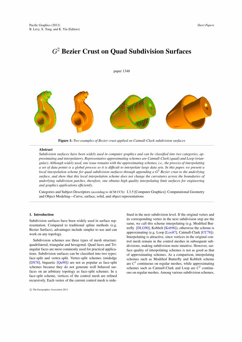
Figure 1: Two examples of Bezier crust applied on Catmull-Clark subdivision surfaces
AbstractSubdivision surfaces have been widely used in computer graphics and can be classified into two categories, ap-proximating and interpolatory. Representative approximating schemes are Catmull-Clark (quad) and Loop (trian-gular). Although widely used, one issue remains with the approximating schemes, i.e., the process of interpolatinga set of data points is a global process so it is difficult to interpolate large data sets. In this paper, we present alocal interpolation scheme for quad subdivision surfaces through appending a G2 Bezier crust to the underlyingsurface, and show that this local interpolation scheme does not change the curvatures across the boundaries ofunderlying subdivision patches, therefore, one obtains high quality interpolating limit surfaces for engineeringand graphics applications efficiently.
Categories and Subject Descriptors (according to ACM CCS): I.3.5 [Computer Graphics]: Computational Geometryand Object Modeling—Curve, surface, solid, and object representations
1. Introduction
Subdivision surfaces have been widely used in surface rep-resentation. Compared to traditional spline methods (e.g.Bezier Surface), advantages include simpler to use and canwork on any topology.
Subdivision schemes use three types of mesh structure:quadrilateral, triangular and hexagonal. Quad faces and Tri-angular faces are most commonly used for practical applica-tions. Subdivision surfaces can be classified into two types:face-split and vertex-split. Vertex-split schemes (midedge[DS78], biquartic [Qu90]) are not as popular as face-splitschemes because they do not generate well behaved sur-faces on an arbitrary topology as face-split schemes. In aface-split scheme, vertices of the control mesh are refinedrecursively. Each vertex of the current control mesh is rede-
fined in the next subdivision level. If the original vertex andits corresponding vertex in the next subdivision step are thesame, we call this scheme interpolating (e.g. Modified But-terfly [DLG90], Kobbelt [Kob96]), otherwise the scheme isapproximating (e.g. Loop [Loo87], Catmull-Clark [CC78]).Interpolating is attractive, since vertices in the original con-trol mesh remain in the control meshes in subsequent sub-divisions, making subdivision more intuitive. However, sur-face quality of interpolating schemes is not as good as thatof approximating schemes. As a comparison, interpolatingschemes such as Modified Butterfly and Kobbelt schemeare C1 continuous on regular meshes, while approximatingschemes such as Catmull-Clark and Loop are C2 continu-ous on regular meshes. Among various subdivision schemes,
c© The Eurographics Association 2013.

/ EG LATEX Author Guidelines
Loop and Catmull-Clark are most widely used on triangularmeshes and quad meshes, respectively.
As an approximating scheme, limit surface of the Loopsubdivision or the Catmull-Clark subdivision (CCS) doesnot interpolate the control mesh in general. However, Sinceconstruction of smooth interpolating surfaces is important inmany applications, including CAD, statistical data modelingand face recognition, it is necessary to develop interpolationtechniques for approximating subdivision schemes. In thispaper, we will address the issue of interpolating quad datameshes, focusing especially on Catmull-Clark scheme.
Given a quad data mesh, the process of calculating a CCScontrol mesh whose limit surface interpolates the given datamesh can be done directly or iteratively. A direct methodsuch as the earlier work of Halstead [HKD93] is not recom-mended because calculating the inverse of a large matrix isnot feasible (the number of data points in an interpolationproblem is typically hundreds or even thousands). Iterativemethods, on the other hand, do not need to compute the in-verse of a large matrix [BT09] [CLT∗08], Some of them evenhave an exponential convergence rate [CLT∗08]. But the in-terpolation is basically an approximating process.
In this paper, we present a simple interpolation schemefor CCS. The new scheme interpolates the given data meshprecisely, instead of iteratively. It works by appending theparametric polynomial of a special bi-quintic Bezier crust toa Catmull-Clark parametric surface. The Bezier crust workson difference vectors between CCS control points and corre-sponding data points, so the new interpolating surface can becomputed locally. There is no need to solve a global linearsystem and the algorithm is efficient and compact. With spe-cial properties of Bezier crust at the boundaries of a surfacepatch, the new interpolation scheme works on an arbitraryquad subdivision surface as well, and will maintain its C1/C2
continuity.
The rest of paper is organized as follows: section 2 re-views previous approaches of mesh interpolation, section 3presents the concept of Bezier crust on space curve, section4 introduces the new interpolating parametric surface by ap-pending tensor-product Bezier crusts to a quad subdivisionsurface with focus on Catmull-Clark, section 5 shows severalimplementations and a discussion, section 6 concludes.
2. Previous Works
In this section, we briefly review earlier methods for inter-polation of given data meshes by quad subdivision schemeof Catmull-Clark and by traditional spline scheme of Beziersurface. The goal of the interpolation is to get a smooth limitsurface that is tangent plane continuous (G1) or curvaturecontinuous (G2). In this paper, we focus on G2 surfaces,which are suitable for most engineering and graphics appli-cations.
2.1. Interpolating Scheme of Catmull-Clark
Catmull-Clark subdivision (CCS) is the most widely usedsubdivision scheme. Control points in a CCS control meshcan be classified into three categories: vertex, edge and face[CC78]. In each CCS, a new face point is created for eachface, a new edge point is created for each edge, and the origi-nal vertex points are updated with new vertex points. By per-forming recursive subdivision, one can obtain a limit surfacethat is C2 everywhere except at extraordinary points, whereit is C1 (tangent plane) continuous only [BS88] [DS78].
Interpolation with a CCS surface can be performed bysolving a linear system,
Ax = b (1)
where A is a square matrix determined by interpolation con-ditions and mesh topology, x is a column vector of controlpoints to be determined, b is a column vector of data pointsin the given data mesh [HKD93]. If A is a small and non-singular matrix, we can obtain the control mesh by calcu-lating A−1 directly first. However, a direct method will notwork or not work well if A is a singular or large matrix. Insuch a case, an iterative method needs to be applied. Tra-ditionally, stationary iterative methods like Jacobi, Gauss-Seidel or Successive Over-relaxation can be used to solvea large linear system. The issue with these methods is theconvergence rate - they are slow when the data set is large.When A is singular, the least-squares method can be applied.There are faster iterative methods to solve larger scale datasets [BT09] [Sze90]. However, since (1) is a global system,convergence rate will still not be satisfactory when we aredealing with thousands of data points.
To avoid dealing with singular linear systems and toimprove iteration speed, a progressive subdivision scheme[CLT∗08] [CFL∗09] has been developed. This method itera-tively generates a new control mesh by adding to old controlmesh the difference between this control mesh and its cor-responding data points on the CCS limit surface and showsthat the linear system developed is positive definite and canimprove the convergence speed of CCS control mesh gener-ation process which satisfies (1).
Besides convergence speed, the interpolating surface ob-tained by solving (1) sometime is unsatisfactory because ofexcessive undulations [HKD93]. Halstead [HKD93] noticesthat the undulations appear because they are not indicatedby the shape of the original mesh. The Fairing techniquesproposed in [LP88] [ZZC01] smooth an interpolating sur-face by including more constraints but increasing the size ofthe control mesh. Some alternative methods [LC06] [ZC06]improve shapes by choosing good initial control mesh oradding more control points to control the shape locally.
The above methods focus on improving convergencespeed of solving (1) or introducing additional constraints tohandle surface artifact, they are all approximating schemes.
c© The Eurographics Association 2013.
/ EG LATEX Author Guidelines
It is natural to ask the following question: "Is it possibleto have a precise interpolating scheme other than approxi-mating ones, without solving a global linear system, but notiterative, while preserving the easy implementation and cur-vature continuity features of CCS?"
2.2. G2 Bezier Surface
In CAGD, Bezier Patch is one of the most widely used repre-sentations in free-form surface modeling. Since each BezierPatch interpolates its 4 corner control points, this makes it anatural choice in surface construction when an interpolatingscheme is desired.
A two-dimensional Bezier surface patch can be defined asa parametric surface,
p(u,v) =n
∑i=0
m
∑j=0
bi,n(u)b j,m(v)Pi, j, (2)
where bi,n(u) and b j,m(v) are Bernstein basis functions ofdegree m and n, respectively, and Pi, j are control points.Since the commonly used Bezier surface patch has m = n,so here we focus on piecewise tensor-product Bezier surfaceonly.
It is clear from the definition (2) that the four corner con-trol points are interpolated by its limit surface. Conditionsof G1 continuity for a piecewise Bezier surface have beendiscussed in [Bez86] [DeR90] [LH89]. It was pointed out,to obtain G1 continuity, one must ensure that partial deriva-tives across the boundary of Bezier patches (n≥ 2) must becoplanar.
In CAGD, G2 continuity is necessary to ensure the ex-istence of a visually well behaved surface. Conditions forG2 continuity are discussed in [Deg90] [Kah83] [YLN96].These works show that, to get G2 continuity, one must haveat least a piecewise biquintic Bezier surface.
Although one can theoretically obtain a piecewise G2
Bezier surface, the construction of such a surface is moredifficult than the construction of a subdivision surface. Onehas to solve a linear system of partial derivatives up to sec-ond order across the boundaries, and the linear system hastoo many degrees of freedom. Gregory reduces the degreeof freedom by introducing additional constraints on internalcontrol points of a Bezier patch [GH89], but its constructionis still not an easy task.
In the above we have reviewed two main interpolatingschemes: subdivision surface based and Bezier patch based.The first scheme is approximating and suffers problems withconvergence speed and undesired undulations, while the lat-ter one is more difficult to construct.
3. Bezier Crust on Space Curve
In this section, we introduce a special quintic Bezier off-set polynomial named Bezier crust on curve. We show that
when a Bezier crust is added to a C2 space curve, the newcurve is C2 with the same tangent and curvature at the startand end points.
A Bezier spline is a composite curve formed by piecingtogether several Bezier curve segments. A Bezier spline in-terpolates all the start and end control points of its Beziercurve segments. While quadratic and cubic Bezier splinesare widely used in font design and 3D animation, they arenot G2 continuous between adjacent Bezier segments. Toobtain a G2 Bezier spline, quintic Bezier curve segments areneeded [Deg90].
A quintic Bezier curve segment takes the following form,
B(t) =5
∑i=0
bi,5(t)Pi, (3)
where bi,5(t) =(5
i)t i(1− t)n−i, i = 0, ..,5, are Bernstein
polynomials of degree 5 and Pi are its control point.
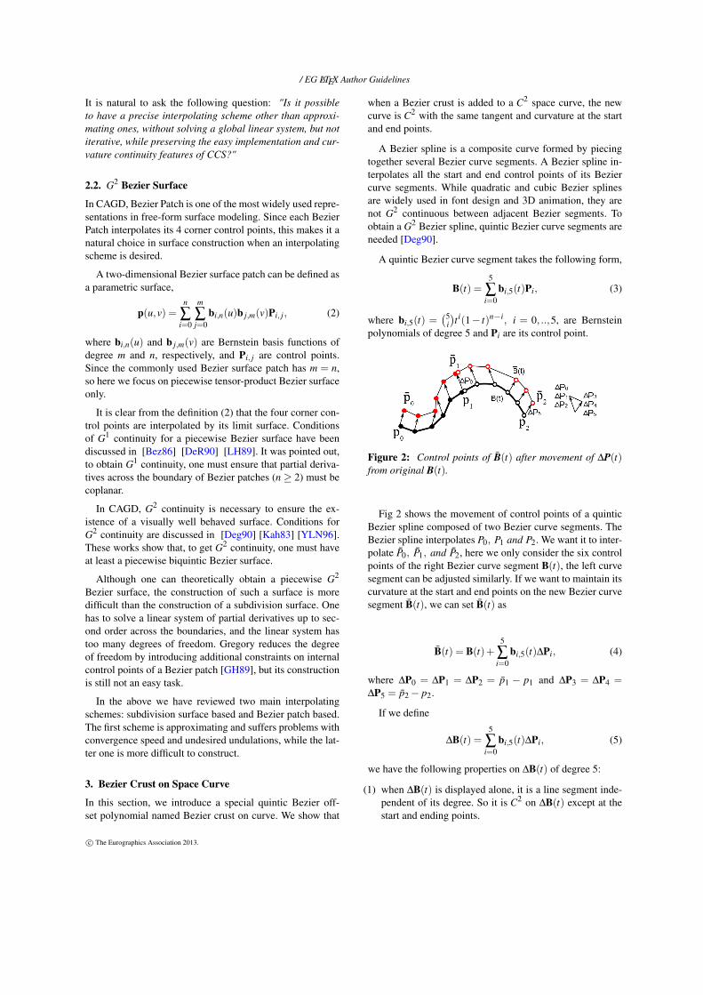
Figure 2: Control points of B̄(t) after movement of ∆P(t)from original B(t).
Fig 2 shows the movement of control points of a quinticBezier spline composed of two Bezier curve segments. TheBezier spline interpolates P0, P1 and P2. We want it to inter-polate P̄0, P̄1, and P̄2, here we only consider the six controlpoints of the right Bezier curve segment B(t), the left curvesegment can be adjusted similarly. If we want to maintain itscurvature at the start and end points on the new Bezier curvesegment B̄(t), we can set B̄(t) as
B̄(t) = B(t)+5
∑i=0
bi,5(t)∆Pi, (4)
where ∆P0 = ∆P1 = ∆P2 = p̄1 − p1 and ∆P3 = ∆P4 =∆P5 = p̄2− p2.
If we define
∆B(t) =5
∑i=0
bi,5(t)∆Pi, (5)
we have the following properties on ∆B(t) of degree 5:
(1) when ∆B(t) is displayed alone, it is a line segment inde-pendent of its degree. So it is C2 on ∆B(t) except at thestart and ending points.
c© The Eurographics Association 2013.

/ EG LATEX Author Guidelines
(2) The 1st and 2nd derivatives of ∆B(t) at the start and endpoints are both zerro. So it will not change the 1st and 2nd
derivatives of B(t) at the start and end points.(3) The new quintic Bezier spline obtained by adding ∆B(t)
to each of the original Bezier curve segments will remainG2 continuous if the original Bezier spline is G2.
With the above properties, we name ∆B(t) of degree 5 aQuintic Bezier crust. We notice that this Quintic Bezier crustcan be added to an arbitrary C2 curve.
THEOREM 1: The new curve obtained by adding aQuintic Bezier crust to a C2 parametric curve is C2 continu-ous and has the same curvature at the start and end point asthe original curve.
PROOF: A C2 parametric curve can be written in poly-nomial form at a parametric value t0 as
f (t) = f (t0)+ f ′(t0)(t− t0)+f ”(t0)
2(t− t0)
2 +δ. (6)
The new curve f̄ (t) = f (t)+∆B(t), by calculating its firstand second derivatives, we can prove that f̄ (t) is C2 and hasthe same curvature at the start and end points as f (t). QED
Since a piecewise cubic B-spline curve is C2, we can addquintic Bezier crust (with difference vectors chosen as dif-ferences between control points and their corresponding datapoints) to each curve segment and obtain a new C2 compos-ite curve which interpolates all control points of the originalcurve (except 1st and last control points if the curve is open).
4. Bezier Crust on Quad Subdivision Surface
In this section, we introduce a new interpolating schemefor quad subdivision surfaces like Catmull-Clark. The newscheme will interpolate a given data mesh exactly.
Quad subdivision schemes have been widely used in sur-face representation because of their simplicity and wellbehaved limit surfaces. Among various quad schemes,Doo Sabin [DS78], Mid-Edge [PR97] are C1 continuous,Catmull-Clark [CC78] is C2 everywhere except at extraordi-nary points. In this paper, we present a new unified interpo-lating scheme for quad approximating subdivision surfaces,with main effort focusing on Catmull-Clark.
Given a quad control mesh M, the CCS scheme generatesa limit surface that approximates the control mesh. The limitsurface of each face f of M (regular or extraordinary) can berepresented in parametric form S(u,v). For each f , we define∆P0, ∆P1, ∆P2 and ∆P3 (Fig 3) as the difference vectorsbetween its corner control points and its corresponding datapoints, respectively. In order to interpolate the corner controlpoints, similar to quintic Bezier crust, we can define a bi-quintic Bezier crust ∆p(u,v) as follows,
∆p(u,v) =5
∑i=0
5
∑j=0
bi,5(u)b j,5(v)∆Pi, j, (7)
where ∆Pi, j are control points of a bi-quintic Bezier surface,and ∆Pi, j = ∆P0 if i ∈ [0,2] & j ∈ [0,2], ∆Pi, j = ∆P1 ifi ∈ [0,2] & j ∈ [3,5], ∆Pi, j = ∆P2 if i ∈ [3,5] & j ∈ [0,2],∆Pi, j = ∆P3 if i ∈ [3,5] & j ∈ [3,5].
Figure 3: Difference vectors between control points andtheir limit points of a regular(left) and an extraordi-nary(right) Catmull-Clark face
When displayed by itself, the Bezier crust defined in (7)has exactly the same boundaries as a bilinear Coons patch.By analyzing the 1st and 2nd order derivatives, we get thefollowing properties of a bi-quintic Bezier crust:
(1) At the four corners, the 1st and 2nd order derivatives van-ish.
(2) At the four boundaries, the 1st and 2nd order derivativesacross the boundaries vanish. Since the difference vectorsalong the boundary are the same for neighboring Beziercrusts, the boundary curve between neighboring Beziercrusts coincides
(3) At (u,v) of the Bezier crust, the 1st and 2nd order deriva-tives are continuous or vanishes.
(4) Bezier crust works on difference vectors at the four cor-ners of a surface patch, so it has the same representationform for both regular and extraordinary face.
By adding the Catmull-Clark parametric form S(u,v) to itsBezier crust ∆p(u,v), we obtain a parametric surface S̄(u,v)which interpolates the four corner control points of f , as fol-lows:
S̄(u,v) = S(u,v)+∆p(u,v) (8)
S(u,v) is computed locally with its (2N + 8) control points(N is the valence). Since the difference vectors can be cal-culated locally with its surrounding (2N +1) control points,∆p(u,v) is also computed locally. So (8) differs from ear-lier CCS interpolation schemes in that it is a local piecewiseparametric surface. Hence, it is not necessary to calculate di-rectly or iteratively a global new control mesh to interpolatea given control mesh (shown in (1)).
THEOREM 2: The limit surface of an interpolating sur-face patch S̄(u,v) defined in (8) is C2 continuous everywhereexcept at extraordinary points.
PROOF: The proof is trivial by properties of the bi-quintic Bezier crust mentioned above. By properties (1) and
c© The Eurographics Association 2013.
/ EG LATEX Author Guidelines
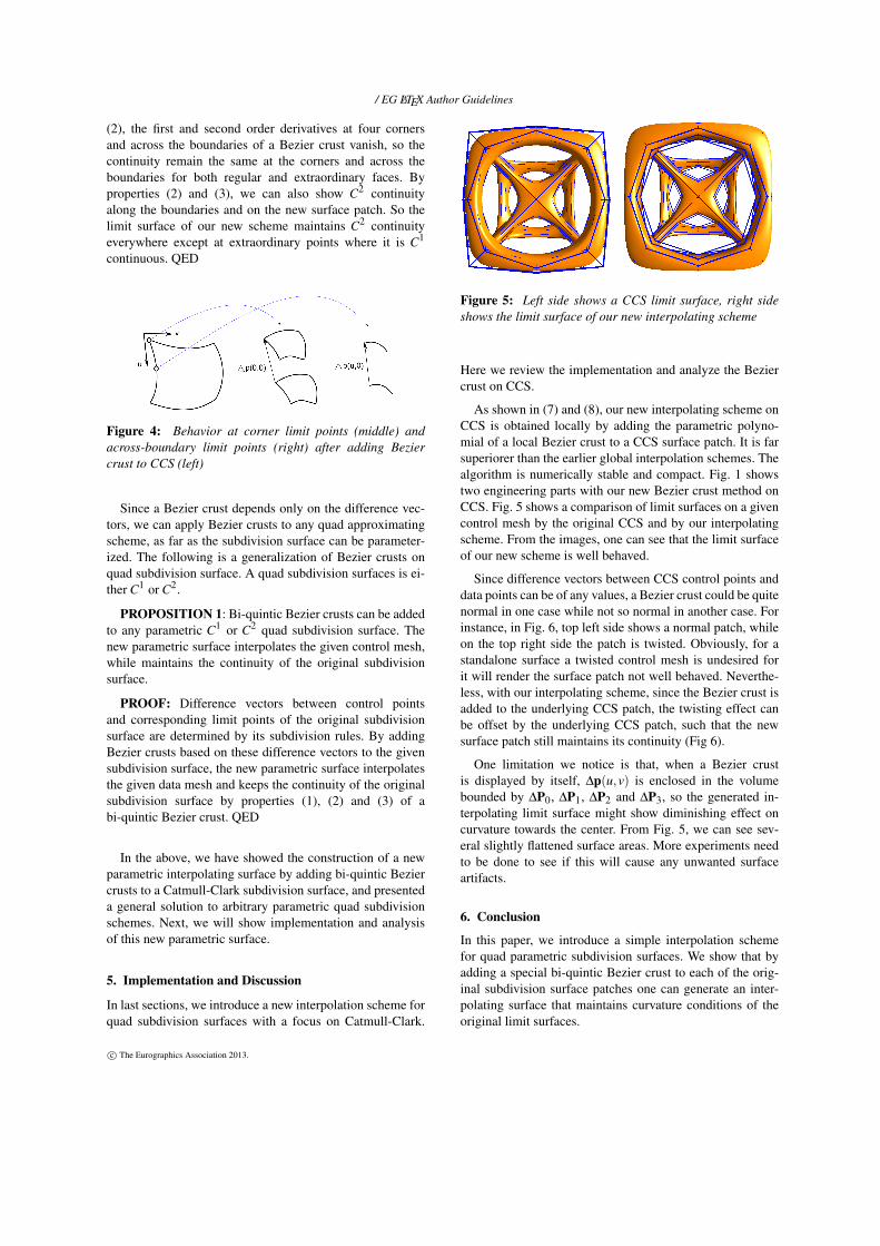
(2), the first and second order derivatives at four cornersand across the boundaries of a Bezier crust vanish, so thecontinuity remain the same at the corners and across theboundaries for both regular and extraordinary faces. Byproperties (2) and (3), we can also show C2 continuityalong the boundaries and on the new surface patch. So thelimit surface of our new scheme maintains C2 continuityeverywhere except at extraordinary points where it is C1
continuous. QED
Figure 4: Behavior at corner limit points (middle) andacross-boundary limit points (right) after adding Beziercrust to CCS (left)
Since a Bezier crust depends only on the difference vec-tors, we can apply Bezier crusts to any quad approximatingscheme, as far as the subdivision surface can be parameter-ized. The following is a generalization of Bezier crusts onquad subdivision surface. A quad subdivision surfaces is ei-ther C1 or C2.
PROPOSITION 1: Bi-quintic Bezier crusts can be addedto any parametric C1 or C2 quad subdivision surface. Thenew parametric surface interpolates the given control mesh,while maintains the continuity of the original subdivisionsurface.
PROOF: Difference vectors between control pointsand corresponding limit points of the original subdivisionsurface are determined by its subdivision rules. By addingBezier crusts based on these difference vectors to the givensubdivision surface, the new parametric surface interpolatesthe given data mesh and keeps the continuity of the originalsubdivision surface by properties (1), (2) and (3) of abi-quintic Bezier crust. QED
In the above, we have showed the construction of a newparametric interpolating surface by adding bi-quintic Beziercrusts to a Catmull-Clark subdivision surface, and presenteda general solution to arbitrary parametric quad subdivisionschemes. Next, we will show implementation and analysisof this new parametric surface.
5. Implementation and Discussion
In last sections, we introduce a new interpolation scheme forquad subdivision surfaces with a focus on Catmull-Clark.
Figure 5: Left side shows a CCS limit surface, right sideshows the limit surface of our new interpolating scheme
Here we review the implementation and analyze the Beziercrust on CCS.
As shown in (7) and (8), our new interpolating scheme onCCS is obtained locally by adding the parametric polyno-mial of a local Bezier crust to a CCS surface patch. It is farsuperiorer than the earlier global interpolation schemes. Thealgorithm is numerically stable and compact. Fig. 1 showstwo engineering parts with our new Bezier crust method onCCS. Fig. 5 shows a comparison of limit surfaces on a givencontrol mesh by the original CCS and by our interpolatingscheme. From the images, one can see that the limit surfaceof our new scheme is well behaved.
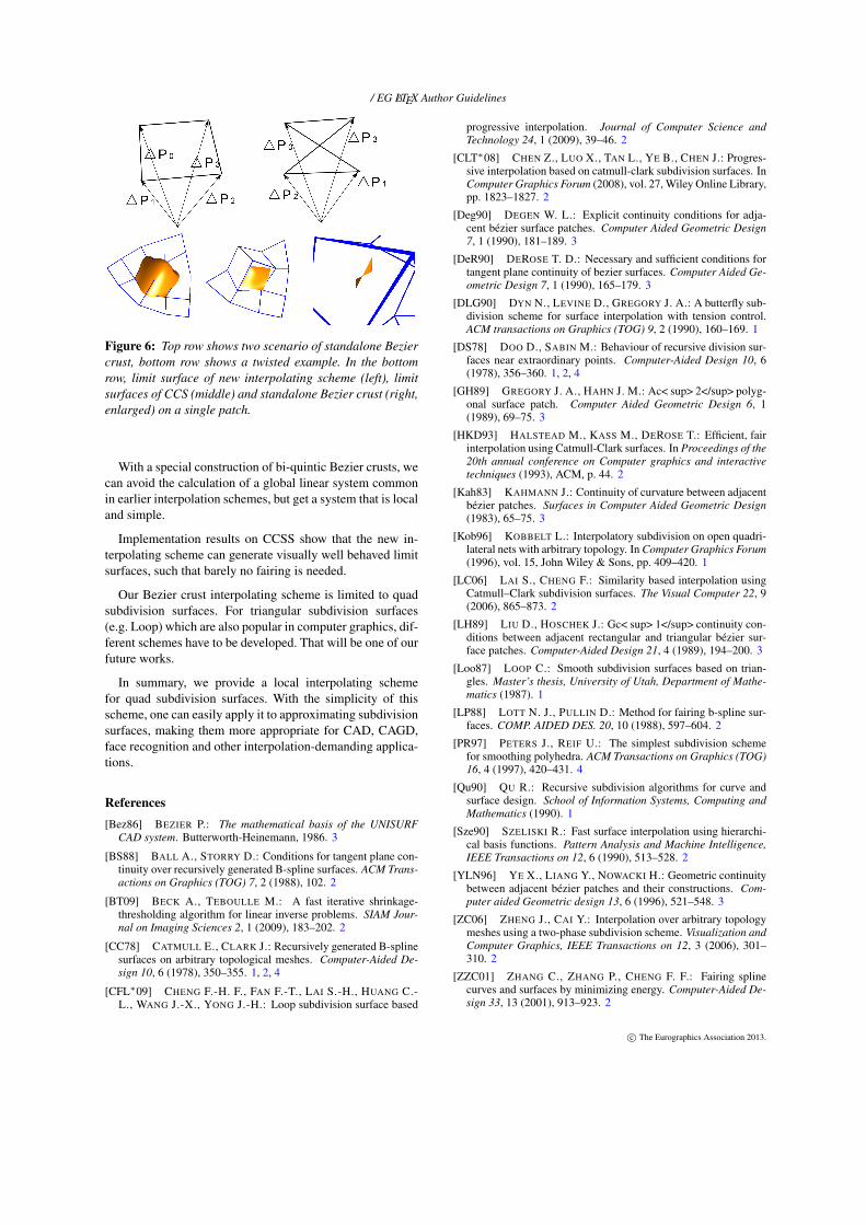
Since difference vectors between CCS control points anddata points can be of any values, a Bezier crust could be quitenormal in one case while not so normal in another case. Forinstance, in Fig. 6, top left side shows a normal patch, whileon the top right side the patch is twisted. Obviously, for astandalone surface a twisted control mesh is undesired forit will render the surface patch not well behaved. Neverthe-less, with our interpolating scheme, since the Bezier crust isadded to the underlying CCS patch, the twisting effect canbe offset by the underlying CCS patch, such that the newsurface patch still maintains its continuity (Fig 6).
One limitation we notice is that, when a Bezier crustis displayed by itself, ∆p(u,v) is enclosed in the volumebounded by ∆P0, ∆P1, ∆P2 and ∆P3, so the generated in-terpolating limit surface might show diminishing effect oncurvature towards the center. From Fig. 5, we can see sev-eral slightly flattened surface areas. More experiments needto be done to see if this will cause any unwanted surfaceartifacts.
6. Conclusion
In this paper, we introduce a simple interpolation schemefor quad parametric subdivision surfaces. We show that byadding a special bi-quintic Bezier crust to each of the orig-inal subdivision surface patches one can generate an inter-polating surface that maintains curvature conditions of theoriginal limit surfaces.
c© The Eurographics Association 2013.
/ EG LATEX Author Guidelines
Figure 6: Top row shows two scenario of standalone Beziercrust, bottom row shows a twisted example. In the bottomrow, limit surface of new interpolating scheme (left), limitsurfaces of CCS (middle) and standalone Bezier crust (right,enlarged) on a single patch.
With a special construction of bi-quintic Bezier crusts, wecan avoid the calculation of a global linear system commonin earlier interpolation schemes, but get a system that is localand simple.
Implementation results on CCSS show that the new in-terpolating scheme can generate visually well behaved limitsurfaces, such that barely no fairing is needed.
Our Bezier crust interpolating scheme is limited to quadsubdivision surfaces. For triangular subdivision surfaces(e.g. Loop) which are also popular in computer graphics, dif-ferent schemes have to be developed. That will be one of ourfuture works.
In summary, we provide a local interpolating schemefor quad subdivision surfaces. With the simplicity of thisscheme, one can easily apply it to approximating subdivisionsurfaces, making them more appropriate for CAD, CAGD,face recognition and other interpolation-demanding applica-tions.
References[Bez86] BEZIER P.: The mathematical basis of the UNISURF
CAD system. Butterworth-Heinemann, 1986. 3
[BS88] BALL A., STORRY D.: Conditions for tangent plane con-tinuity over recursively generated B-spline surfaces. ACM Trans-actions on Graphics (TOG) 7, 2 (1988), 102. 2
[BT09] BECK A., TEBOULLE M.: A fast iterative shrinkage-thresholding algorithm for linear inverse problems. SIAM Jour-nal on Imaging Sciences 2, 1 (2009), 183–202. 2
[CC78] CATMULL E., CLARK J.: Recursively generated B-splinesurfaces on arbitrary topological meshes. Computer-Aided De-sign 10, 6 (1978), 350–355. 1, 2, 4
[CFL∗09] CHENG F.-H. F., FAN F.-T., LAI S.-H., HUANG C.-L., WANG J.-X., YONG J.-H.: Loop subdivision surface based
progressive interpolation. Journal of Computer Science andTechnology 24, 1 (2009), 39–46. 2
[CLT∗08] CHEN Z., LUO X., TAN L., YE B., CHEN J.: Progres-sive interpolation based on catmull-clark subdivision surfaces. InComputer Graphics Forum (2008), vol. 27, Wiley Online Library,pp. 1823–1827. 2
[Deg90] DEGEN W. L.: Explicit continuity conditions for adja-cent bézier surface patches. Computer Aided Geometric Design7, 1 (1990), 181–189. 3
[DeR90] DEROSE T. D.: Necessary and sufficient conditions fortangent plane continuity of bezier surfaces. Computer Aided Ge-ometric Design 7, 1 (1990), 165–179. 3
[DLG90] DYN N., LEVINE D., GREGORY J. A.: A butterfly sub-division scheme for surface interpolation with tension control.ACM transactions on Graphics (TOG) 9, 2 (1990), 160–169. 1
[DS78] DOO D., SABIN M.: Behaviour of recursive division sur-faces near extraordinary points. Computer-Aided Design 10, 6(1978), 356–360. 1, 2, 4
[GH89] GREGORY J. A., HAHN J. M.: Ac< sup> 2</sup> polyg-onal surface patch. Computer Aided Geometric Design 6, 1(1989), 69–75. 3
[HKD93] HALSTEAD M., KASS M., DEROSE T.: Efficient, fairinterpolation using Catmull-Clark surfaces. In Proceedings of the20th annual conference on Computer graphics and interactivetechniques (1993), ACM, p. 44. 2
[Kah83] KAHMANN J.: Continuity of curvature between adjacentbézier patches. Surfaces in Computer Aided Geometric Design(1983), 65–75. 3
[Kob96] KOBBELT L.: Interpolatory subdivision on open quadri-lateral nets with arbitrary topology. In Computer Graphics Forum(1996), vol. 15, John Wiley & Sons, pp. 409–420. 1
[LC06] LAI S., CHENG F.: Similarity based interpolation usingCatmull–Clark subdivision surfaces. The Visual Computer 22, 9(2006), 865–873. 2
[LH89] LIU D., HOSCHEK J.: Gc< sup> 1</sup> continuity con-ditions between adjacent rectangular and triangular bézier sur-face patches. Computer-Aided Design 21, 4 (1989), 194–200. 3
[Loo87] LOOP C.: Smooth subdivision surfaces based on trian-gles. Master’s thesis, University of Utah, Department of Mathe-matics (1987). 1
[LP88] LOTT N. J., PULLIN D.: Method for fairing b-spline sur-faces. COMP. AIDED DES. 20, 10 (1988), 597–604. 2
[PR97] PETERS J., REIF U.: The simplest subdivision schemefor smoothing polyhedra. ACM Transactions on Graphics (TOG)16, 4 (1997), 420–431. 4
[Qu90] QU R.: Recursive subdivision algorithms for curve andsurface design. School of Information Systems, Computing andMathematics (1990). 1
[Sze90] SZELISKI R.: Fast surface interpolation using hierarchi-cal basis functions. Pattern Analysis and Machine Intelligence,IEEE Transactions on 12, 6 (1990), 513–528. 2
[YLN96] YE X., LIANG Y., NOWACKI H.: Geometric continuitybetween adjacent bézier patches and their constructions. Com-puter aided Geometric design 13, 6 (1996), 521–548. 3
[ZC06] ZHENG J., CAI Y.: Interpolation over arbitrary topologymeshes using a two-phase subdivision scheme. Visualization andComputer Graphics, IEEE Transactions on 12, 3 (2006), 301–310. 2
[ZZC01] ZHANG C., ZHANG P., CHENG F. F.: Fairing splinecurves and surfaces by minimizing energy. Computer-Aided De-sign 33, 13 (2001), 913–923. 2
c© The Eurographics Association 2013.