g - tests w/codes - 2 - celicatechbgbonline.celicatech.com/94_6gmanual/g tests with codes...
TRANSCRIPT

G - TESTS W/CODES - 2.2L
1994 Toyota Celica
1994 ENGINE PERFORMANCE Toyota 2.2L Self-Diagnostics
Celica
INTRODUCTION
If no faults were found while performing F - BASIC TESTING,proceed with self-diagnostics. If no Diagnostic Trouble Codes (DTC)are present after entering self-diagnostics, proceed to steps inH - TESTS W/O CODES article for diagnosis by symptom (i.e., ROUGHIDLE, NO START, etc.).
NOTE: Diagnostic Trouble Codes (DTC) will be referred to as trouble codes in this article.
SELF-DIAGNOSTIC SYSTEM
Hard Failures Hard failures cause Malfunction Indicator Light (MIL) oninstrument panel to illuminate and remain on until problem isrepaired. If light comes on and remains on (light may flash) duringvehicle operation, corresponding trouble code will be retained inElectronic Control Module (ECM) memory on some trouble codeapplications. Not all trouble codes are retained in ECM memory. Thecause of malfunction must be determined using trouble code charts. Ifa sensor fails, Electronic Control Module (ECM) will use a substitutevalue in its calculations to continue engine operation. In thiscondition, commonly known as limp-in mode, the vehicle runs butdriveability will not be optimum.
NOTE: The MIL may also be referred to as the CHECK ENGINE light. The MIL may not illuminate when certain failure such as faulty starter signal or A/C switch signal exists, or if certain trouble codes are set.
Intermittent Failures Intermittent failures may cause Malfunction Indicator Light(MIL) to flicker or illuminate and go out after intermittent faultgoes away. However, the corresponding trouble code will be retained inECM memory on some trouble code applications. Not all trouble codesare retained in ECM memory. Intermittent failures may be caused by asensor, connector or wiring related problem. See INTERMITTENTS inH - TESTS W/O CODES article.
NOTE: Test Mode (if equipped) and Normal Mode on self-diagnostic system are used for retrieving trouble code from ECM memory. For information on different mode usage, see RETRIEVING TROUBLE CODES.
RETRIEVING TROUBLE CODES
NOTE: Trouble codes may be retrieved using Toyota scan tester in Normal Mode or Test Mode.
NOTE: Normal Mode is used to retrieve trouble code from Electronic Control Module (ECM) to determine problem area. Test Mode is used to check for trouble codes when operating vehicle to simulate conditions in which trouble code was set. Test mode

contains a higher sensing ability to detect malfunctions. Test Mode helps determine malfunctions caused by poor electrical connections, which are difficult to determine using Normal Mode. Test Mode also checks for malfunction in starter signal circuit, A/C switch signal and Park/Neutral switch signal.
NOTE: The Malfunction Indicator Light (MIL) on the instrument panel may also be referred to as CHECK ENGINE light.
Toyota Scan Tester Connect scan tester to appropriate Data Link Connector (DLC).See Fig. 1. DLC No. 1 is used on all models. Using scan testermanufacturer’s instructions, retrieve trouble codes.
Normal Mode 1) Before retrieving trouble code(s), verify MIL oninstrument panel comes on with ignition on and engine off. The MILshould go off when engine is started. 2) If MIL does not come on with ignition on and engine off,check bulb circuit on instrument panel and wiring circuit between MILand ECM. See appropriate wiring diagram in L - WIRING DIAGRAMSarticle. See ECM LOCATION. 3) If MIL remains on, self-diagnostic system has detected amalfunction or abnormality. Ensure battery voltage is greater than 11volts and charging system is okay. Warm engine to normal operatingtemperature. 4) Apply parking brake. Shift the transmission/transaxle intoNeutral (M/T) or Park (A/T). Turn A/C and all accessories off. Ensurethrottle is in idle position. 5) Turn ignition on with engine off. Install Jumper Wire (SST09843-18020) between terminals TE1 and E1 in appropriate Data LinkConnector (DLC). See Fig. 1. 6) Count number of flashes from MIL on instrument panel. Ifsystem is operating properly (with no trouble codes), MIL will flashcontinuously and evenly. See Fig. 2. 7) If MIL will not flash, check TE1 and E1 wiring circuit.See appropriate TE1 & TE2 DIAGNOSTIC CIRCUIT CHECK chart under TROUBLECODE CHARTS. See ECM LOCATION. 8) If trouble code exists, digits of trouble code will beflashed at approximately 1/2-second intervals. A 1 1/2-second pauseseparates first and second digits of code. See Fig. 2. 9) If more than one trouble code is stored, a 2 1/2-secondpause will occur before next trouble code is flashed. Once all troublecodes are displayed, a 4 1/2-second pause will occur then troublecode(s) will be repeated. 10) Trouble codes are displayed in order of smallest tolargest. After trouble codes are retrieved, remove jumper wire to exitNormal Mode. See NOTES ON TROUBLE CODES. For additional information ontrouble codes, see TROUBLE CODE DIAGNOSTIC HINTS table under SELF-DIAGNOSTIC SYSTEM and appropriate TROUBLE CODE IDENTIFICATION tableunder TROUBLE CODE IDENTIFICATION.
NOTE: To repair failure causing trouble code, refer to proper trouble code chart under TROUBLE CODE CHARTS. Once repairs for trouble code are made, trouble code must be cleared from ECM memory. See CLEARING TROUBLE CODES.
Test Mode 1) Before retrieving trouble code(s), verify MIL oninstrument panel comes on with ignition on and engine off. The MILshould go off when engine is started. 2) Check bulb circuit on instrument panel and wiring circuit

between MIL and ECM. See appropriate wiring diagram information inL - WIRING DIAGRAMS article. See ECM LOCATION. 3) Ensure battery voltage is greater than 11 volts andcharging system is okay. Apply parking brake. Shift thetransmission/transaxle to Neutral (M/T) or Park (A/T). Turn A/C andall accessories off. Ensure throttle is in idle position and ignitionis off.
NOTE: Test Mode will not operate if jumper wire is installed between terminals TE2 and E1 in Data Link Connector (DLC) after ignition is turned on.
4) Install Jumper Wire (SST 09843-18020) between terminalsTE2 and E1 in Data Link Connector (DLC) with ignition off. See Fig. 1. 5) Turn ignition on with engine off. Test Mode is operationalif MIL on instrument panel flashes. 6) If MIL fails to flash, check TE2 wiring circuit. Seeappropriate TE1 & TE2 DIAGNOSTIC CIRCUIT CHECK chart under TROUBLECODE CHARTS. See ECM LOCATION. 7) Drive vehicle at a speed greater than 6 MPH. ECM will setTrouble Codes 42 and 43 if vehicle is not driven. Try to simulateconditions of driveability complaint described by customer, and notewhen MIL comes on. This indicates when problem exists. 8) Stop vehicle, but DO NOT turn engine off. Install jumperwire between terminals TE1 and E1 in DLC. See Fig. 1. Count number offlashes from MIL on instrument panel. If system is operating properly(with no trouble codes), MIL will flash continuously and evenly. SeeFig. 2. 9) If trouble code exists, digits of trouble code will beflashed at approximately 1/2-second intervals. A 1 1/2-second pauseseparates first and second digits of code. See Fig. 2. 10) If more than one trouble code is stored, a 2 1/2-secondpause will occur before next trouble code is flashed. Once all troublecodes are displayed, a 4 1/2-second pause will occur, then troublecode(s) will be repeated. Trouble codes are displayed in order ofsmallest to largest.
NOTE: On all models, Trouble Code 51 will normally be displayed if automatic transmission/transaxle is in any gear except Park or Neutral, A/C is turned on, or accelerator pedal is depressed.
11) After trouble code(s) is retrieved, remove jumper wiresto exit Test Mode. See NOTES ON TROUBLE CODES. For additionalinformation on trouble codes, see TROUBLE CODE DIAGNOSTIC HINTS tableunder SELF-DIAGNOSTIC SYSTEM and appropriate TROUBLE CODEIDENTIFICATION table under TROUBLE CODE IDENTIFICATION.
NOTE: The MIL may not come on if certain trouble code is set when in Test Mode. See appropriate TROUBLE CODE IDENTIFICATION table under TROUBLE CODE IDENTIFICATION.
NOTE: To repair failure causing trouble code, refer to proper trouble code chart under TROUBLE CODE CHARTS. Once repairs for trouble code are made, trouble code must be cleared from ECM memory. See CLEARING TROUBLE CODES.

Fig. 1: Data Link Connector ID & Installing Jumper Wire (Celica)Courtesy of Toyota Motor Sales, U.S.A., Inc.
Fig. 2: Identifying Normal System Operation & Trouble Code Using MILCourtesy of Toyota Motor Sales, U.S.A., Inc.
NOTES ON TROUBLE CODES

1) When certain trouble codes occur, MIL on instrument panelwill not come on. For designation of MIL operation on certain troublecodes, see appropriate TROUBLE CODE IDENTIFICATION table under TROUBLECODE IDENTIFICATION. 2) When certain malfunctions or trouble codes initiallyoccur, they will be temporarily stored in ECM memory, but MIL oninstrument panel will not come on. 3) The second time malfunction or trouble code is detected,MIL on instrument panel will then come on, provided ignition is turnedoff and then back on after malfunction or trouble code was firstdetected. This is referred to as the Two Trip Detection Logic and onlyapplies to specified trouble codes. See TWO TRIP DETECTION LOGICTROUBLE CODES table.
NOTE: When road testing vehicle in Test Mode, the Two Trip Detection Logic will not function. In Test Mode, the MIL on instrument panel will come on the first time malfunction or trouble code is detected.
TWO TRIP DETECTION LOGIC TROUBLE CODES TABLE�����������������������������������������������������������������������������������������������������������������������Application (1) Trouble Code
Celica ............................... 21, 25, 26, 27 & 71
(1) - Trouble codes may not apply to all models, as some trouble codes are used only on Calif. models.�������������������������������������������������������������������������������������������������������������������������������������������
4) In Normal Mode, MIL on instrument panel will go off aftermalfunction is repaired, but trouble codes, except ECM non-memorytrouble codes, will be retained in ECM memory until cleared. ECM non-memory trouble codes are not stored in ECM memory. See ECM NON-MEMORYTROUBLE CODES table. 5) In Test Mode (if equipped), all trouble codes except ECMnon-memory trouble codes are retained in ECM memory, even withignition off and repairs made, until cleared. ECM non-memory troublecodes are not retained in ECM memory. See ECM NON-MEMORY TROUBLE CODEStable.
NOTE: When in Test Mode, if vehicle is not driven at a speed greater than 6 MPH, ECM will set Trouble Codes 42 and 43. For MIL operation in relation to trouble code when in Test Mode, see appropriate TROUBLE CODE IDENTIFICATION table under TROUBLE CODE IDENTIFICATION.
ECM NON-MEMORY TROUBLE CODES TABLE�����������������������������������������������������������������������������������������������������������������������Application Trouble Code
Normal Mode.................................... 16, 43 & 51Test Mode ........................................ 43 & 51�����������������������������������������������������������������������������������������������������������������������
CLEARING TROUBLE CODES
1) After performing repairs, clear ECM memory of all storedtrouble codes. To clear memory, turn ignition off. Remove proper fusefrom fuse/relay box for approximately 30 seconds or more. See FUSEAPPLICATION table and FUSE/RELAY BOX LOCATION table. 2) Depending on ambient temperature, fuse may need to beremoved for more than 30 seconds, especially in colder temperatures.Install fuse. Road test vehicle. Ensure system operates properly (with

no trouble codes) and MIL flashes continuously and evenly. See Fig. 2.
NOTE: Trouble codes may also be cleared by disconnecting negative battery cable. However, other memory functions (clock, radio, alarm, seats, etc.) will be cancelled and must be reset.
3) With certain trouble codes, once trouble code has beencleared from ECM memory, a trouble code detection driving pattern testcan be performed to verify repairs and that trouble has not reset. Forinformation on trouble code detection driving pattern test, seeTROUBLE CODE DETECTION DRIVING PATTERN TESTS.
FUSE APPLICATION TABLE�����������������������������������������������������������������������������������������������������������������������Model Fuse (Amps)
Celica .......................................... EFI (15)�����������������������������������������������������������������������������������������������������������������������
FUSE/RELAY BOX LOCATION TABLE�����������������������������������������������������������������������������������������������������������������������Application Location
Celica .... Driver Side, Front Corner Of Engine Compartment�������������������������������������������������������������������������������������������������������������������������
TROUBLE CODE DETECTION DRIVING PATTERN TESTS
NOTE: Trouble code driving pattern test may be referred to as driving pattern test.
1) With certain trouble codes, once trouble code has beencleared from ECM memory, a trouble code detection driving pattern testcan be performed to verify repairs and that trouble has not reset.Trouble code driving pattern test will duplicate conditions requiredto set specified trouble codes. 2) Trouble code detection driving pattern test listsprocedure to be performed to ensure trouble code has not reset. SeeFig. 3. 3) Trouble code detection driving pattern tests apply only tospecified trouble codes. See TROUBLE CODE DETECTION DRIVING PATTERNTEST APPLICATION table. Trouble code detection driving pattern testwill be included with proper trouble code chart under TROUBLE CODECHARTS.
TROUBLE CODE DETECTION DRIVING PATTERN TEST APPLICATION TABLE�����������������������������������������������������������������������������������������������������������������������������Model (1) Trouble Code
Celica .............................. 21, 25, 26, 27, 52 & 71
(1) - Trouble codes listed may not apply to all models, as some trouble codes are used only on Calif. models.�����������������������������������������������������������������������������������������������������������������������������

Fig. 3: Typical Trouble Code Detection Driving Pattern TestCourtesy of Toyota Motor Sales, U.S.A., Inc.
ECM LOCATION
NOTE: For illustration of ECM location, refer to information in E - THEORY/OPERATION article.
ECM LOCATION TABLE�����������������������������������������������������������������������������������������������������������������������Model Location
Celica ................... Below Passenger’s Side Of Dash, Underneath The Carpet�����������������������������������������������������������������������������������������������������������������������
TROUBLE CODE DIAGNOSTIC HINTS
NOTE: To determine a common cause for a trouble code to be set, see TROUBLE CODE DIAGNOSTIC HINTS table.
TROUBLE CODE DIAGNOSTIC HINTS TABLE (1)�������������������������������������������������������������������������������������������������������������������������������������������Trouble Code Diagnostic Hints
12 ............... No "G", "G1", "G2" or "NE" Ignition Signal To ECM Within 2 Seconds After Engine Is Cranked, No "G" Ignition Signal To ECM For 3 Seconds

With Engine Speed Of 600-4000 RPM Open In "G-" Circuit13 ............................. No "NE" Ignition Signal To ECM When Engine Speed Is Greater Than Approximately 1000 RPM, No "G" Ignition Signal To ECM When "NE" Signal Is Input 4 Times With Engine Speed Of 600-4000 RPM14 .................... No "IG" Or "IGF" Ignition Signal To ECM From Ignitor Several Times In Succession16 ...................... Fault In Transmission/Transaxle ECU Or ECM21 .............................. Defective O2 Sensor, Open Or Short Circuit In O2 Sensor Signal22 ......................... Open Or Short Circuit In Engine Coolant Temperature Sensor Signal24 ......... Open Or Short Circuit In Intake Air Temp. Sensor Signal25 ............... Lean Signal Sent By O2 Sensor For Several Seconds26 ............... Rich Signal Sent By O2 Sensor For Several Seconds27 ................... Open Or Short Circuit In Sub-O2 Sensor Signal28 ............................................ Defective O2 Sensor, Open Or Short Circuit In O2 Sensor Signal31 ................................ Open Or Short Circuit In Airflow Meter Or MAP Sensor Signal32 ........... Open Or Short Circuit Between Airflow Meter Terminals34 ............................... Turbocharger Pressure Is Abnormal35 ................. Open Or Short Circuit In Turbocharging Pressure Sensor, MAP Sensor Or BARO Sensor41 ........ Open Or Short Circuit In Throttle Position Sensor Signal42 ............................. No Signal From Vehicle Speed Sensor For Several Seconds43 ..................... No "STA" Signal To ECM Until Engine Reaches 800 RPM With Engine Cranking47 .... Open Or Short Circuit In Sub-Throttle Position Sensor Signal51 ............... (2) Problem In One Of 3 Circuits Monitored By ECM52 .................... Open Or Short Circuit In Knock Sensor Signal53 .................................. Knock Control In ECM Is Faulty55 .................... Open Or Short Circuit In Knock Sensor Signal71 ................................... EGR Gas Temperature Less Than Predetermined Level During EGR Control78 ...................... Open Or Short Circuit In Fuel Pump Control Circuit Or Fuel Pump Electronic Control Unit (ECU)81 ................. Open In ECT1 Circuit Between ECM & Transmission Control Module (TCM) For At Least 2 Seconds83 ................. Open In ESA1 Circuit Between ECM & Transmission Control Module (TCM) For 1/2 Second After Engine Idles At Least 1/2 Second84 ................. Open In ESA2 Circuit Between ECM & Transmission Control Module (TCM) For 1/2 Second After Engine Idles At Least 1/2 Second85 ................. Open In ESA3 Circuit Between ECM & Transmission Control Module (TCM) For 1/2 Second After Engine Idles At Least 1/2 Second
(1) - Listed are possible areas causing trouble codes. Not all trouble codes are used on all models.(2) - Throttle position sensor, Park/Neutral switch and A/C Signal circuits are monitored.�������������������������������������������������������������������������������������������������������������������������������������������
TROUBLE CODE IDENTIFICATION
TROUBLE CODE IDENTIFICATION TABLE������������������������������������������������������������������������������������������������������������������������������������������Code
� System
�(2)
�(2)
�Probable Cause
�

�Number
� Affected
�MIL
�MIL
�
��
�
�In
�In
�
��
�
�Normal
�Test
�
��
�
�Mode
�Mode
�
�� ���������������������������������������������������������������������������������������������������������������������������������������12
�RPM Signal
�ON
�N/A
�Distributor, Starter
��
�
�
�
�Or Circuit, ECM
�� ���������������������������������������������������������������������������������������������������������������������������������������13
�RPM Signal
�(3)
�(4)
�Distributor Or
��(2.2L)
�
�
�
�Circuit, ECM
�� ���������������������������������������������������������������������������������������������������������������������������������������14
�Ignition
�ON
�N/A
�Ignitor Or Circuit To
��
�Signal
�
�
�ECM, ECM
�� ���������������������������������������������������������������������������������������������������������������������������������������16 (5)
�A/T Control
�ON
�N/A
�ECM Or Circuit
��
�Signal
�
�
�
�� ���������������������������������������������������������������������������������������������������������������������������������������21
�Oxygen Sensor
�ON
�ON
�Oxygen Sensor Or
��
�Signal
�
�
�Circuit, ECM
�� ���������������������������������������������������������������������������������������������������������������������������������������22
�Engine Coolant
�ON
�ON
�Engine Coolant Temp.
��
�Temperature
�
�
�Sensor Or Circuit, ECM
��
�Sensor Signal
�
�
�
�� ���������������������������������������������������������������������������������������������������������������������������������������24
�Intake Air
�ON
�ON
�Intake Air Temp. Sensor
��
�Temperature
�
�
�Or Circuit, ECM
�� ���������������������������������������������������������������������������������������������������������������������������������������25
�Lean Air/Fuel
�
�
�Injector Or Circuit,
��
�Mixture
�
�
�Oxygen Sensor Or
��
�
�
�
�Circuit Fuel Pressure,
��
�
�
�
�Ignition System,
��
�
�
�
�Vacuum Leak,
��
�
�
�
�Compression Pressure,
��
�
�
�
�ECM
�� ���������������������������������������������������������������������������������������������������������������������������������������26
�Rich Air/Fuel
�ON
�ON
�Injector Or Circuit,
��
�Mixture
�
�
�Oxygen Sensor Or
��
�
�
�
�Circuit Fuel Pressure,
��
�
�
�
�Ignition System,
��
�
�
�
�Vacuum Leak,
��
�
�
�
�Compression Pressure,
��
�
�
�
�ECM
�� ���������������������������������������������������������������������������������������������������������������������������������������27
�Sub-Oxygen
�ON
�ON
�Sub-Oxygen Sensor Or
��
�Sensor
�
�
�Circuit, ECM
��
�Signal
�
�
�
�� ���������������������������������������������������������������������������������������������������������������������������������������31
�MAP Sensor
�ON
�ON
�MAP Sensor Or Circuit,
��
�Signal
�
�
�ECM
�� ���������������������������������������������������������������������������������������������������������������������������������������41
�Throttle
�ON
�ON
�Throttle Position
��
�Position
�
�
�Sensor Or Circuit, ECM
��
�Sensor
�
�
�
��
�Signal
�
�
�
�� ���������������������������������������������������������������������������������������������������������������������������������������42
�Vehicle Speed
�ON
�OFF
�Vehicle Speed Sensor
��(2.2L)
�Sensor Signal
�
�
�Or Circuit, ECM
�� ���������������������������������������������������������������������������������������������������������������������������������������43
�Starter
�N/A
�OFF
�Starter Signal Circuit,
��
�Signal
�
�
�Starter Relay, Ignition
��
�
�
�
�Switch Or Circuit, ECM
�� ���������������������������������������������������������������������������������������������������������������������������������������51
�Switch
�N/A
�OFF
�A/C Switch Circuit,
�

�
�Condition
�
�
�Park/Neutral Switch Or
��
�Signal
�
�
�Circuit, TPS Or
��
�
�
�
�Circuit, ECM
�� ���������������������������������������������������������������������������������������������������������������������������������������52
�Knock Sensor
�ON
�N/A
�Knock Sensor Or
��
�Signal
�
�
�Circuit, ECM
�� ���������������������������������������������������������������������������������������������������������������������������������������71
�EGR System
�ON
�ON
�EGR System, EGR Temp.
��
�Malfunction
�
�
�Sensor Or Circuit,
��
�
�
�
�EGR-VSV, ECM
�� �����������������������������������������������������������������������������������������������������������������������������������(1) - The 1.8L is the 7A-FE engine and 2.2L is the 5S-FE engine.
��(2) - ON indicates MIL on instrument panel will be illuminated.
�� N/A indicates item is not included in malfunction diagnosis
�� when using this mode. OFF indicates MIL on instrument panel
�� will not be illuminated even if malfunction is detected.
��(3) - The MIL will be illuminated only if no "NE" signal is sent
�� to ECM with engine at approximately 1000 RPM (Calif. models)
�� or 1500 RPM (all others).
��(4) - The MIL will be illuminated only if no "G" signal is sent to
�� ECM at least 4 times with engine speed between 500 and 4000
�� RPM. Also, on Calif. models, when in Test Mode, MIL will be
�� illuminated if "NE" signal does not pulse 12 times to ECM
�� during interval between "G1" and "G2" pulses.
��(5) - Applies only to models with electronic-controlled automatic
�� transaxle.
�� ���������������������������������������������������������������������������������������������������������������������������������������
TROUBLE CODE CHARTS
ECM TERMINAL IDENTIFICATION
Fig. 4: ECM Terminal IdentificationCourtesy of Toyota Motor Sales, U.S.A., Inc.
DIAGNOSTIC CIRCUIT CHECK ("TE1" & "TE2" TERMINAL CIRCUIT)
Terminals "TE1" and "TE2" are located in Data Link Connectors(DLC) No. 1. DLC is located in engine compartment. When theseterminals are connected/jumpered with the DLC "E1" terminal,Diagnostic Trouble Codes (DTC) can be accessed in the normal or testmodes using the Malfunction Indicator Light (MIL) located in theinstrument cluster. Check for an open or short in wiring harness or for faultyECM if test mode or output is not activated when DLC terminals "TE1"and "TE2" is jumpered to DLC terminal "E1" or when MIL blinks eventhough these terminals are not connected or jumpered.

Fig. 5: Diagnostic Circuit Check - SchematicCourtesy of Toyota Motor Sales, U.S.A., Inc.

Fig. 6: Diagnostic Circuit Check - Diagnostic FlowchartCourtesy of Toyota Motor Sales, U.S.A., Inc.
ECM POWER SOURCE CIRCUIT CHECK
When ignition switch is turned on, battery positive voltageis applied to ignition coil, closing contacts in EFI main relay andsupplying power to terminals +B and +B1 of ECM.

Fig. 7: ECM Power Source Circuit Check - SchematicCourtesy of Toyota Motor Sales, U.S.A., Inc.

Fig. 8: ECM Power Source Circuit Check - Diagnostic Flowchart (1Of 2)Courtesy of Toyota Motor Sales, U.S.A., Inc.

Fig. 9: ECM Power Source Circuit Check - Diagnostic Flowchart (2Of 2)Courtesy of Toyota Motor Sales, U.S.A., Inc.
ECM BACK-UP POWER SOURCE CIRCUIT CHECK
Battery positive voltage is supplied to BATT terminal of ECMeven when ignition switch is turned off for use by the diagnostictrouble code memory, air/fuel ratio adaptive control value memory,

etc.
Fig. 10: ECM Back-Up Power Source Circuit Check - SchematicCourtesy of Toyota Motor Sales, U.S.A., Inc.

Fig. 11: ECM Back-Up Power Source Circuit Check - DiagnosticFlowchartCourtesy of Toyota Motor Sales, U.S.A., Inc.
DTC 12 - RPM SIGNAL (EXCEPT CALIF.)
The distributor assembly contains 3 pick-up coils. The "G"signal informs ECM of the standard crankshaft position. The "NE"signal informs ECM of the crankshaft position and engine speed.

If "NE" signal is not present to ECM within 2 seconds or morewith engine cranking, check for open or short in the "G" or "NE"circuit, or for faulty distributor. If "G" signal is not present from ECM for 3 seconds or morewith engine speed of 600-4000 RPM, check for open or short in "STA"circuit or for a faulty ECM.
Fig. 12: DTC 12 - SchematicCourtesy of Toyota Motor Sales, U.S.A., Inc.

Fig. 13: DTC 12 - Inspection Using OscilloscopeCourtesy of Toyota Motor Sales, U.S.A., Inc.

Fig. 14: DTC 12 - Diagnostic FlowchartCourtesy of Toyota Motor Sales, U.S.A., Inc.
DTC 12 - RPM SIGNAL (CALIF.)
The distributor assembly contains 3 pick-up coils. The "G1"and "G2" signals inform ECM of the standard crankshaft position. The"NE" signal informs ECM of the crankshaft position and engine speed. If "G1", "G2" or "NE" signal is not present to ECM within 2seconds or more with engine cranking, check for open or short in the"G" or "NE" circuit, or for faulty distributor. If "G" signal is not present to ECM for 3 seconds or morewith engine speed between 600-4000 RPM, check for open or short in"STA" circuit or for a faulty ECM.

Fig. 15: DTC 12 - SchematicCourtesy of Toyota Motor Sales, U.S.A., Inc.

Fig. 16: DTC 12 - Diagnostic Flowchart (1 Of 2)Courtesy of Toyota Motor Sales, U.S.A., Inc.

Fig. 17: DTC 12 - Diagnostic Flowchart (2 Of 2)Courtesy of Toyota Motor Sales, U.S.A., Inc.
DTC 13 - RPM SIGNAL
This code indicates that a momentary interruption of the "G"and "NE" signal from the distributor to ECM has occurred, but hasreturned to normal. This malfunction is usually a loose or dirtyconnector or terminal. For further diagnosis, refer to appropriate DTC12 chart.
DTC 14 - IGNITION SIGNAL
ECM determines ignition timing. ECM turns on "Tr1" circuit at

a predetermined angle before desired ignition timing, and outputs anignition signal to the Integrated Ignition Assembly (IIA). Since thewidth of the "IGT" signal is constant, dwell angle control circuit inthe IIA determines the time control circuit starts primary currentflow to ignition coil, based on engine RPM and ignition timing onerevolution ago, that is, the time "Tr2" circuit turns on. When it reaches the ignition timing, ECM turns off "Tr1" andoutputs the "IGT" signal "0". This turns off "Tr2", interrupting theprimary current flow and generating a high voltage in the secondarycoil, firing the spark plugs. Also, by the counter electromotive forcegenerated when the primary current is interrupted, the ignitor sendsan ignition confirmation signal (IGF) to the ECM. The ECM stops fuelinjection as a fail safe function when "IGF" signal is not input toECM. If "IGF" signal to ECM is not present after 4 consecutive"IGT" signals, check for open or short in "IGF" or "IGT" circuit fromdistributor to ECM. Check for faulty ignitor or ECM.

Fig. 18: DTC 14 - SchematicCourtesy of Toyota Motor Sales, U.S.A., Inc.

Fig. 19: DTC 14 - Diagnostic Flowchart (1 Of 5)Courtesy of Toyota Motor Sales, U.S.A., Inc.

Fig. 20: DTC 14 - Diagnostic Flowchart (2 Of 5)Courtesy of Toyota Motor Sales, U.S.A., Inc.

Fig. 21: DTC 14 - Diagnostic Flowchart (3 Of 5)Courtesy of Toyota Motor Sales, U.S.A., Inc.

Fig. 22: DTC 14 - Diagnostic Flowchart (4 Of 5)Courtesy of Toyota Motor Sales, U.S.A., Inc.

Fig. 23: DTC 14 - Diagnostic Flowchart (5 Of 5)Courtesy of Toyota Motor Sales, U.S.A., Inc.
DTC 16 - ECT CONTROL SIGNAL
Signal from automatic transmission CPU retards engineignition timing during shifting, thus momentarily reducing enginetorque output for smooth clutch operation and reduce shift roughness. If there is a fault in communications between ECM and A/TCPU, check for faulty ECM. Fault will set DTC 16 and prohibitstransmission torque control.

Fig. 24: DTC 16 - Diagnostic FlowchartCourtesy of Toyota Motor Sales, U.S.A., Inc.
DTC 21 - OXYGEN SENSOR SIGNAL
This code sets when the main oxygen sensor signal voltage isreduced between .35-.70 volt for 60 seconds under the followingconditions:
* Engine coolant temperature at 176 F (80 C) or greater. * Engine speed at 1500 RPM or greater. * Engine load. * Main oxygen sensor signal voltage alternating at greater than or less than .45 volt.

Fig. 25: DTC 21 - SchematicCourtesy of Toyota Motor Sales, U.S.A., Inc.

Fig. 26: DTC 21 - Inspection Using OscilloscopeCourtesy of Toyota Motor Sales, U.S.A., Inc.

Fig. 27: DTC 21 - Detection Driving PatternCourtesy of Toyota Motor Sales, U.S.A., Inc.
Fig. 28: DTC 21 - Diagnostic FlowchartCourtesy of Toyota Motor Sales, U.S.A., Inc.
DTC 22 - ENGINE COOLANT TEMPERATURE SENSOR SIGNAL
The engine coolant temperature sensor is a thermistor thatchanges its resistance value according to engine coolant temperature.ECM supplies a 5-volt reference voltage to engine coolant temperaturethrough ECM terminal "E6". When sensor resistance changes, ECM changesfuel injection volume to improve driveability during cold engineoperation. A failure code is set when there is an open or short inengine coolant temperature sensor circuit for .5 second or more. Checkfor open or short in engine coolant temperature sensor circuit, afaulty sensor or ECM.

Fig. 29: DTC 22 - SchematicCourtesy of Toyota Motor Sales, U.S.A., Inc.

Fig. 30: DTC 22 - Voltage Reference ChartCourtesy of Toyota Motor Sales, U.S.A., Inc.

Fig. 31: DTC 22 - Diagnostic FlowchartCourtesy of Toyota Motor Sales, U.S.A., Inc.
DTC 24 - INTAKE AIR TEMPERATURE SENSOR SIGNAL
Intake Air Temperature (IAT) sensor is built into air cleanercover. The IAT sensor senses the intake air temperature. If ECMdetects a problem in this circuit, it operates in the fail safe modein which the intake air temperature is assumed to be 68 F (20 C). A failure code is set there is an open or short in IAT sensorcircuit for .5 second or more. Check for open or short in IAT circuit,a faulty IAT sensor or ECM.

Fig. 32: DTC 24 - SchematicCourtesy of Toyota Motor Sales, U.S.A., Inc.

Fig. 33: DTC 24 - Diagnostic FlowchartCourtesy of Toyota Motor Sales, U.S.A., Inc.
DTC 25/26 - LEAN OR RICH AIR/FUEL MIXTURE
DTC 25 is set under following conditions: * Main oxygen sensor voltage is .45 volt or less (lean) for 90 seconds when engine coolant temperature is at 140 F (60 C) or greater, and engine speed at 1500 RPM or greater. * Engine speed varies by greater than 15 RPM over the preceding crank position period during a period of 30 seconds or more with engine idling and engine coolant temperature at 140 F (60 C) or

greater.
DTC 26 is set under following conditions: * Engine speed varies by greater than 15 RPM over the preceding crank position during a period of 50 seconds or more with engine idling and engine coolant temperature at 140 F (60 C) or greater.
Fig. 34: DTC 25/26 - Detection Driving PatternCourtesy of Toyota Motor Sales, U.S.A., Inc.

Fig. 35: DTC 25/26 - Diagnostic Flowchart (1 Of 4)Courtesy of Toyota Motor Sales, U.S.A., Inc.

Fig. 36: DTC 25/26 - Diagnostic Flowchart (2 Of 4)Courtesy of Toyota Motor Sales, U.S.A., Inc.

Fig. 37: DTC 25/26 - Diagnostic Flowchart (3 Of 4)Courtesy of Toyota Motor Sales, U.S.A., Inc.

Fig. 38: DTC 25/26 - Diagnostic Flowchart (4 Of 4)Courtesy of Toyota Motor Sales, U.S.A., Inc.
DTC 27 - SUB-OXYGEN SENSOR SIGNAL (CALIF.)
DTC 27 is set when the main oxygen sensor signal is .45 voltor greater and sub-oxygen sensor signal is .45 volt or less whenengine coolant temperature is at 176 F (80 C) or greater and enginespeed at 1500 RPM or greater with accelerator pedal fully depressedfor more than 2 seconds. Check for open or shorted circuit in sub-oxygen sensorcircuit, a faulty sub-oxygen sensor or ECM.

Fig. 39: DTC 27 - SchematicCourtesy of Toyota Motor Sales, U.S.A., Inc.
Fig. 40: DTC 27 - Detection Driving PatternCourtesy of Toyota Motor Sales, U.S.A., Inc.

Fig. 41: DTC 27 - Diagnostic FlowchartCourtesy of Toyota Motor Sales, U.S.A., Inc.
DTC 31 - MAP SENSOR SIGNAL
MAP sensor detects the intake manifold absolute pressure as avoltage. ECM determines basic injection duration and basic ignitionadvance angle based on this voltage. DTC 31 sets when there is an openor short in MAP sensor circuit for .5 second or more. Check for anopen or shorted MAP sensor circuit, a faulty MAP sensor or ECM.

Fig. 42: DTC 31 - SchematicCourtesy of Toyota Motor Sales, U.S.A., Inc.

Fig. 43: DTC 31 - Output Voltage/Absolute Pressure Reference ChartCourtesy of Toyota Motor Sales, U.S.A., Inc.

Fig. 44: DTC 31 - Diagnostic FlowchartCourtesy of Toyota Motor Sales, U.S.A., Inc.
DTC 41 - THROTTLE POSITION SENSOR SIGNAL
DTC 41 is set when there is an open or short in throttleposition sensor circuit for .5 second or greater. Code will not setwhen throttle position connector is disconnected. Check for open orshort in throttle position sensor circuit, a faulty throttle positionsensor or ECM.

Fig. 45: DTC 41 - SchematicCourtesy of Toyota Motor Sales, U.S.A., Inc.

Fig. 46: DTC 41 - Diagnostic Flowchart (1 Of 2)Courtesy of Toyota Motor Sales, U.S.A., Inc.

Fig. 47: DTC 41 - Diagnostic Flowchart (2 Of 2)Courtesy of Toyota Motor Sales, U.S.A., Inc.
DTC 42 - VEHICLE SPEED SENSOR SIGNAL
The No. 1 vehicle speed sensor outputs a 4-pulse signal forevery revolution of the rotor shaft, which is rotated by transmissionoutput shaft. ECM determines vehicle speed based on the frequency ofthese pulse signals. DTC 42 is set when following conditions are detectedcontinuously for 8 seconds or more:
* On vehicles equipped with A/T, No. 1 vehicle speed signal reads zero MPH with engine speed at 3000 RPM or greater and with P/N switch off. * On vehicles equipped with M/T, No. 1 vehicle speed signal reads zero MPH with engine speed at 3000-5000 RPM, engine coolant temperature at 176 F (80 C) or greater and with drive wheels turning (driving load).
Check for open or short in No. 1 vehicle speed sensorcircuit, a faulty No. 1 vehicle speed sensor, a faulty combinationmeter or ECM.

Fig. 48: DTC 42 - SchematicCourtesy of Toyota Motor Sales, U.S.A., Inc.

Fig. 49: DTC 42 - Voltage Reference ChartCourtesy of Toyota Motor Sales, U.S.A., Inc.
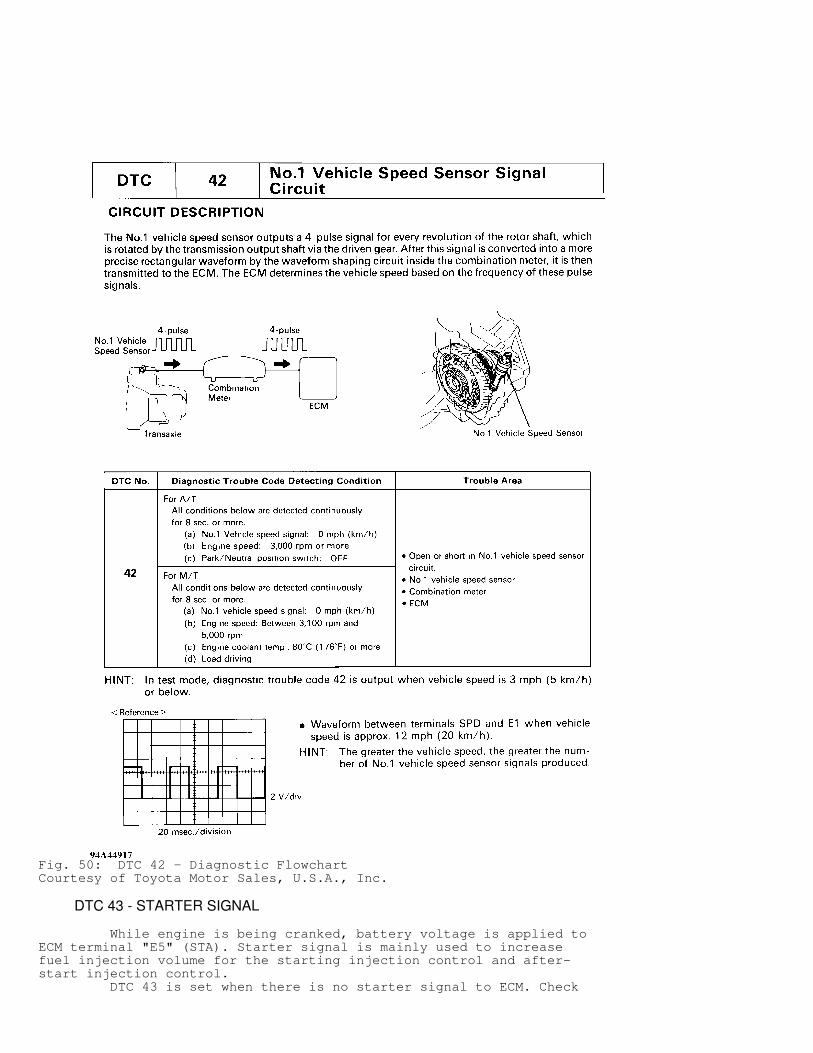
Fig. 50: DTC 42 - Diagnostic FlowchartCourtesy of Toyota Motor Sales, U.S.A., Inc.
DTC 43 - STARTER SIGNAL
While engine is being cranked, battery voltage is applied toECM terminal "E5" (STA). Starter signal is mainly used to increasefuel injection volume for the starting injection control and after-start injection control. DTC 43 is set when there is no starter signal to ECM. Check

for open or short in starter signal circuit, an open or short inignition switch or starter relay circuit or a faulty ECM.
Fig. 51: DTC 43 - SchematicCourtesy of Toyota Motor Sales, U.S.A., Inc.

Fig. 52: DTC 43 - Diagnostic FlowchartCourtesy of Toyota Motor Sales, U.S.A., Inc.
DTC 51 - SWITCH CONDITION SIGNAL
ECM uses Park/Neutral (P/N) position switch signal todetermine whether transmission is in Park or Neutral, or in some othergear. ECM uses the output from A/C switch to determine whether ornot A/C is operating, so that it can increase idle speed if necessary. ECM detects idle condition through "IDL" terminal of throttleposition sensor. DTC 51 is set when throttle position switch is off for 3seconds or more after engine starts. P/N position switch is off withshift position in either Reverse, Drive or Low (A/T). A/C switch on.Check throttle position sensor "IDL" circuit, accelerator pedal andcable adjustment, P/N position switch circuit, A/C switch circuit orfor faulty ECM.

Fig. 53: DTC 51 - SchematicCourtesy of Toyota Motor Sales, U.S.A., Inc.

Fig. 54: DTC 51 - Diagnostic Flowchart (1 Of 2)Courtesy of Toyota Motor Sales, U.S.A., Inc.

Fig. 55: DTC 51 - Diagnostic Flowchart (2 Of 2)Courtesy of Toyota Motor Sales, U.S.A., Inc.
DTC 52 - KNOCK SENSOR SIGNAL
DTC 52 is set when ECM detects an open or short in the knocksensor circuit with engine speed of 1200-6000 RPM. Check for open orshort in knock sensor circuit, a loose or faulty knock sensor orfaulty ECM.

Fig. 56: DTC 52 - SchematicCourtesy of Toyota Motor Sales, U.S.A., Inc.

Fig. 57: DTC 52 - Detection Driving PatternCourtesy of Toyota Motor Sales, U.S.A., Inc.
Fig. 58: DTC 52 - Inspection Using OscilloscopeCourtesy of Toyota Motor Sales, U.S.A., Inc.

Fig. 59: DTC 52 - Diagnostic Flowchart (1 Of 2)Courtesy of Toyota Motor Sales, U.S.A., Inc.

Fig. 60: DTC 52 - Diagnostic Flowchart (2 Of 2)Courtesy of Toyota Motor Sales, U.S.A., Inc.
DTC 71 - EGR SYSTEM MALFUNCTION
DTC 71 is set when EGR temperature is 140 � F (60 � C) or lessfor 50 seconds under the following conditions:
* Engine coolant temperature at 140 � F (80 � C) or greater. * EGR operation possible. Except A/T in 3rd gear or M/T in 5th gear, cruising at 55-60 MPH on a flat road.
Check for open in EGR temperature sensor circuit, a shortedEGR VSV circuit, a plugged EGR passage or a faulty ECM.

Fig. 61: DTC 71 - SchematicCourtesy of Toyota Motor Sales, U.S.A., Inc.

Fig. 62: DTC 71 - Detection Driving PatternCourtesy of Toyota Motor Sales, U.S.A., Inc.

Fig. 63: DTC 71 - Diagnostic Flowchart (1 Of 3)Courtesy of Toyota Motor Sales, U.S.A., Inc.

Fig. 64: DTC 71 - Diagnostic Flowchart (2 Of 3)Courtesy of Toyota Motor Sales, U.S.A., Inc.

Fig. 65: DTC 71 - Diagnostic Flowchart (3 Of 3)Courtesy of Toyota Motor Sales, U.S.A., Inc.
SUMMARY
If no hard trouble codes are present, driveability symptomsexist or intermittent trouble codes exist, proceed to steps inH - TESTS W/O CODES article for diagnosis by symptom (i.e., ROUGHIDLE, NO START, etc.) or intermittent procedures.