>g · 2013-08-31 · mined by substituting the maximum and minimum illuminations, lmax and emin,...
TRANSCRIPT

I
I.
i N A S a T E C H N I C A L NASA TM X-2089 MEMORANDUM
w Q =? >G
OPTICAL POLARIMETRIC PROPERTIES OF THE MaTEIUALS IN THE PACEQS I AND ECHO IT SATELLITE S-URFACES
by Robert Be if2 Let! 11-
https://ntrs.nasa.gov/search.jsp?R=19700030074 2020-04-24T10:20:14+00:00Z
*For sale by the Clearinghouse for Federal Scientific and Technical Information
Springfield. Virginia 22151
3. Recipient's Catalog No.
5. Report Date September 1970
6. Performing Organization Code
8. Performing Organization Report No.
L-6749 10. Work Unit No.
124-09-26-01
11. Contract or Grant No.
13. Type of Report and Period Covered
Technical Memorandum
14. Sponsoring Agency Code
1. Report No.
NASA TM X-2089
2. Government Accession No.
15. Supplementary Notes
16. Abstract
Laboratory measurements were made of the percent polarization of light reflected from materials representative of those in the PAGEOS I and Echo I1 satellite surfaces. The percent polarization was determined as a function of phase angle (angle between the incident and reflected light) from lo0 to 168O in the ultraviolet, blue, and visual spectral
bands. The PAGEOS I surface material was vapor-deposited aluminum on poly(ethy1ene terephthalate) film (PET), whereas the Echo I1 surface had an alodine (amorphous phosphate) coating chemically formed to a rolled aluminum-foil substrate. The polarization for the
PAGEOS I surface was found to be in agreement with that calculated for vapor-deposited aluminum. The polarization for the Echo I1 surface was found to be greater than that for the rolled aluminum-foil substrate, both being dependent upon the orientation of the sub- strate line structure with respect to the plane of incidence.
.
17. Key Words (Suggested by Author(s))
Polarization
Reflectance Amorphous phosphate coating Aluminum
4, Title and Subtitle
OPTICAL POLARIMETRIC PROPERTIES OF THE MATERIALS IN THE PAGEOS I AND ECHO I1 SATELLITE SURFACES
7. Author(s1
Robert Benjamin Lee 111
9. Performing Organization Name and Address
NASA Langley Research Center
Hampton, Va. 23365
12. Sponsoring Agency Name and Address
National Aeronautics and Space Administration
Washington, D.C. 20546
18. Distribution Statement
Unclassified - Unlimited
22. Price*
$3.00 21. No. of Pages
15 19. Security Classif. (of this report)
Unclassified 20. Security Classif. (of this page)
Unclassified
OPTICAL POLARIMETRIC PROPERTIES O F THE mTERIALS
IN THE PAGEOS I AND ECHO 11 SATELLITE SURFACES
By Robert Benjamin Lee 111
Langley Research Center
SUMMARY
Laboratory measurements were made of the percent polarization of light reflected
from materials representative of those in the PAGEOS I and Echo I1 satellite surfaces. The percent polarization was determined a s a function of phase angle (angle between the
incident and reflected light) f rom 10° to 1680 in the ultraviolet, blue, and visual spectral
bands. The PAGEOS I surface material was vapor-deposited aluminum on poly(ethy1ene
terephthalate) fi lm (PET), whereas the Echo II surface had an alodine (amorphous phos-
phate) coating chemically formed to a rolled aluminum-foil substrate. The polarization
for the PAGEOS I surface was found to be in agreement with that calculated for vapor-
deposited aluminum. The polarization for the Echo I1 surface was found to be greater than that for the rolled aluminum-foil substrate, both being dependent upon the orientation
of the substrate line s t ructure with respect to the plane of incidence.
INTRODUCTION
The PAGEOS I (Passive Geodetic Earth Orbiting Satellite) is a 30.48-meter-
diameter inflatable aluminized balloon of poly(ethy1ene terephthalate) fi lm (hereinafter
called PET) with a highly reflective surface. It was launched in 1966 as part of the
National Geodetic Satellites Program (ref. 1). The Echo I1 satellite i s a 41.15-meter-
diameter inflatable balloon with an alodine (amorphous phosphate) coating formed to a rolled aluminum-foil surface. It was launched in 1964 a s par t of a passive satell i tes
communication program (ref. 2).
Sunlight incident upon the PAGEOS I and Echo 11 surfaces becomes partially polar-
ized upon reflection. The degree of polarization is dictated by the optical surface prop- e r t ies of the satell i tes and the phase angle (angle between the incident and reflected light)
of the reflected sunlight. Therefore, ground-based polarimetric observations of the
satell i tes were initiated in 1967 to determine from variations in the polarization the effects of long-term exposure of their surfaces to the space environment. In the observations,
the percent polarization of the sunlight reflected from each satellite was measured by the

Satellite Photometric Observatory (ref. 3) as a function of phase angle in the ultraviolet,
blue, and visual spectral bands.
In order to assist in the analysis of the ground-based polarimetric measurements
of these satellites, laboratory measurements were made of the percent polarization of
light reflected from materials representative of these satellites. The laboratory mea-
surements were performed by using optical techniques similar to those used in the satel-
lite observations, and the results a re given in this report.
SYMBOLS
The units used for the physical quantities defined in this paper a r e given in the
International System of Units (SI). Factors relating this system to U.S. Customary Units
a re given in reference 4.
ko coefficient of absorption
maximum illumination, measured behind a rotating linear analyzer,
lumen/centimeters2
minimum illumination, measured behind a rotating linear analyzer,
lumen/centimeterZ
complex index of refraction
real index of refraction
polarization, percent
Principal ,Angle of Incidence, degrees
Brewsterls angle, degrees
bngle of incidence, measured between incident light and surface normal,
degrees
i angle of reflection, measured between specularly reflected light and surface
normal, degrees
@2 angle of refraction, measured between refracted light and surface normal,
reflected fraction of incident light vibrating perpendicular to the plane of
incidence
reflected fraction of incident light vibrating parallel t o the plane of
incidence
phase angle, measured between incident and reflected light, degrees
THEORY
Dielectrics and metals introduce linear and elliptical polarization, respectively, t o
reflected light. The dominant vibration direction of the reflected light is generally per - pendicular to the plane of incidence. The percent polarization P of the specularly
reflected light can be calculated by means of the equation for polarization which is
P = Py - Pco x 100 percent py + pco
where p and p, a r e the reflected fractions of the incident light vibrating perpen- Y
dicular and parallel , respectively, t o the plane of incidence.
For optically smooth dielectrics, P~
and p, can be described by Fresnel 's
formulas (ref. 5) as
and
- ran:' tan 0' + - y2 0
where 81 and O2 a r e the angles of incidence and refraction, respectively. By applying
Snellqs Law where n = s in el/sin 82, equations (2) and (3) a r e modified to
cos - n cos 82
cos 81 + n cos 82
and
n cos 81 - cos 82
n cos Q1 + cos 82 (5)
where n is the r e a l index of refraction. For equation (5), pw becomes zero when
el + B2 = 90° (where 82 is related to by Snellls Law), thus leaving the reflected
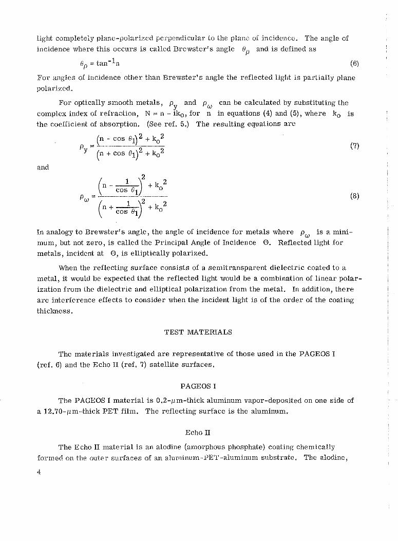
light completely plane-polarized perpendicular to the plane of incidence. The angle of
incidence where this occurs is called Brewsterqs angle Qp and is defined a s
op = tan-In (6)
For angles of incidence other than Brewstervs angle the reflected light is partially plane
polarizedi
For optically smooth metals, P~
and pW can be calculated by substituting the
complex index of refraction, N = n - iko, for n in equations (4) and (5), where ko is
the coefficient of absorption. (See ref. 5.) The resulting equations a r e
Py = (n + cos + k02 (7)
and
In analogy t o Brewster 's angle, the angle of incidence for metals where p, is a mini-
mum, but not zero, is called the Principal Angle of Incidence @. Reflected light for metals, incident a t 0, is elliptically polarized.
When the reflecting surface consists of a semitransparent dielectric coated to a metal, it would be expected that the reflected light would be a combination of l inear polar-
ization f rom the dielectric and elliptical polarization f rom the metal. In addition, there
a r e interference effects t o consider when the incident light is of the order of the coating
thickness.
TEST MATERIALS
The materials investigated a r e representative of those used in the PAGEOS I
(ref. 6) and the Echo I1 (ref. 7) satellite surfaces.
PAGEOS I
The PAGEOS I material is 0.2-pm-thick aluminum vapor-deposited on one side of
a 12.70-pm-thick PET film. The reflecting surface is the aluminum,
Echo 11
The Echo 11 material is an alodine (amorphous phosphate) coating chemically formed on the outer surfaces of an aluminum-PET-aluminum substrate. The alodine,
4

a semitransparent dielectric, has an average surface density of 1-99 X 10-4 gm/crn2.
The substrate is composed of 8,89-pn1-thick PET film adhesively bonded between two
layers of 4.57-pm-thick rolled aluminum foil. The foil has a fine line structure (see
fig, 1) that resul ts f rom rolling aluminum in thin gages (ref. 8). The line structure
gives the Echo lI surface roughly the geometry of a reflection diffraction grating. The
reflecting surface is the alodine -coated aluminum foil.
Figure 1.- Micrograph of the Echo I1 aluminum-foil substrate, illus- trating the surf ace line structure. Micrograph made in oblique light at 50 x magnification .
Both materials were placed in a sample holder, resembling an embroidery hoop,
under s t r e s s t o obtain flat reflecting surfaces.
TEST APPARATUS
The polarization measurements were made by using an optical bench photometer
which is a monoplane goniophotometer equipped with linear polarization analyzers. The
optical bench photometer is shown in figure 2, and a schematic diagram of the light path
is shown in figxre 3. The output of the source is passed through an aperture stop, col-
limated into a 0.635-em-diameter beam by a collimating lens, and then filtered by a color
fi l ter before striking the tes t material. The light, specularly (el = ~ i ) reflected from
the tes t material at a preselected phase angle, is then passed through a rotating linear
analyzer, a field stop, depolarizer, and then is focused onto the photomultiplier-tube
entrance slit by a condensing lens. A description of the photometer components is given
in table I,
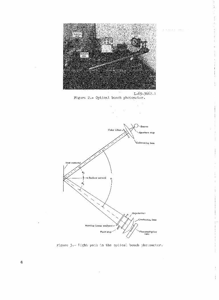
L-69-3662. 1 Figure 2.- Optical bench photometer.
Figure 3.- Light pa,th i n t he o p t i c a l bench photometer.

TABLE 1.- COMPONENTS O F OPTICAL BENCH PHOTOMETER
I Component 1 Description I Source . . . . . . . . . . . . Aperture stop . . . . . . . .
Zirconium-concentrated a r c lamp
0.1-cm-diameter opening
Collimating lens . . . . . . . Color fi l ter . . . . . . . . . . Rotating linear analyzer . . .
I Photomultiplier tube . . . . . I S-4 response
Fused quartz; focal length, 10.00 cm
Standard astronomical ultraviolet, blue, and visual
HNB'P (ultraviolet) and HN38 (blue and visual)
Field stop . . . . . . . . . . Depolarizer . . . . . . . . .
Condensing lens . . . . . . .
The photometer has stationary and movable a r m s which permit phase-angle settings
from 10° to 16a0, and also a turntable connected to the sample holder to vary the angle of
incidence from -90' to 90°.
The percent polarization P of the light reflected from test surfaces was deter-
mined by substituting the maximum and minimum illuminations, Lmax and Emin, respectively, measured behind the rotating linear analyzer into the following equation:
2 .O-cm-diameter opening
Two calcite disks, 0.15 and 0.20 cm thick,
cemented with their optical axes at 45O
Fused quartz; focal length, 8.30 cm
P = Lmax - 'lnin x 100 percent Lmax + Lmin
(9)
The illuminations Lmax and Lmin correspond to p and pw, respectively. This Y
was the same method used to measure the percent polarization for the PAGEOS I and
Echo I1 by using the NASA Satellite Photometric Observatory. The laboratory measure-
ments were made in the ultraviolet, blue, and visual spectral bands centered around wave-
lengths of 0.36, 0.44, and 0.55 pm, respectively, and were confined to the plane of
incidence.
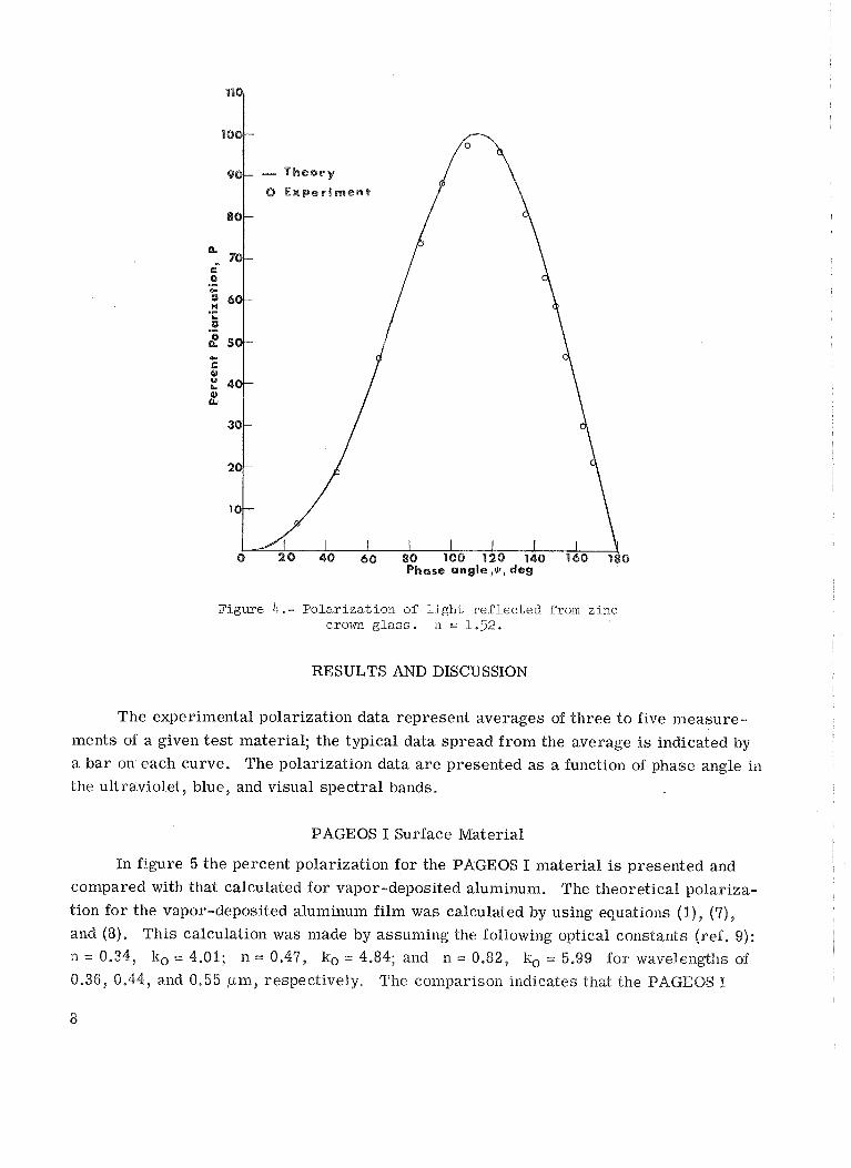
The polarization introduced by the tes t apparatus was determined by measuring the
polarization of light reflected from zinc crown glass and comparing it to that calculated
for the glass. The two se t s of data a r e compared in figure 4 where the percent polariza-
tion P is plotted against phase angle II/ for the visual band. The theoretical polariza- tion was calculated by using equations (I) , (4), and (5) and by assuming that 11 = 1.52 for
the glass. The comparison shows good agreement between theory and experiment. Therefore, the test apparatus appears to produce reasonable polarization n~easurernents.
u 80 100 120 Phase angle ,@, 1
Figure 4.- Polarization of light reflected from zinc crown glass. n = 1.52.
RESULTS AND DISCUSSION
The experimental polarization data represent averages of three to five measure-
ments of a given tes t material; the typical data spread from the average i s indica-ted by
a bar on each curve. The polarization data a r e presented a s a function of phase angle in
the ultraviolet, blue, and visual spectral bands.
PAGEOS I Surface Material
In figure 5 the percent polarization fo r the PAGEOS I material is presented and
compared with that calculated for vapor-deposited aluminum. The theoretical polariza-
tion for the vapor-deposited aluminum film was calculated by using equations (I), (7),
and (8). This calculation was made by assuming the following optical constants (ref, 9): n = 0.34, ko = 4.01; n = 0.41, kco = 4.84; and 11 = 0.82, & = 5.99 for wavelengths of
0.36, 0.44, and 0.55 pm, respectively. The comparison indicates that the PAGEOS I

P h a s e angle,$,deg
( a ) Ul t ravio le t spec t r a l band.
(b ) Blue s p e c t r a l band.
Figure 5.- Polar iza t ion i n t h e specular d i rec t ion ($ = eel) f o r t h e PAGEOS I material . Bars indi-
ca t e typica,l spread of da ta .

Phase angle,*, deg
(c) Visual spectral band.
Figure 5. - Concluded. polarization agrees with that for vapor-deposited aluminum within -+I percent polariza-
tion (10 percent of the maximum polarization), and that the polarization increases with
increasing wavelength and peaks at high phase angles.
Echo I1 Surface Material
In figure 6 the percent polarization of light reflected from both the Echo I1 (alodine
coated) and the aluminum-foil substrate is presented fo r the substrate line s t ructure
oriented parallel and perpendicular to the plane of incidence. The data for both the coated
material and substrate i l lustrate that the polarization is dependent upon the orientation
of the substrate line structure. For low phase angles, the polarization was found to be
slightly grea te r with the surface line structure oriented perpendicular t o the plane of
incidence than with it parallel. However, for high phase angles, the polarization was
found t o be greater when the line s t ructure was oriented parallel to the plane of incidence
than when it was perpendicular. The resul ts for low phase angles agree with trends
expected for reflection diffraction gratings (refs. 10 and 11). The resul ts for high phase
angles a r e , at present, unexplained. The differences in polarization attributed to the
orientation of the line s t ructure a r e less for the Echo 11 material than for the aluminum
substrate.
As shown in figure 6 , the Echo I1 material polarizes the incident light to a greater degree than the aluminum substrate in each spectral band. The maximum differences in

Phase angle,^, deg
(a) Ul t ravio le t spec t r a l band.
Figure 6.- E'olarization i n the specular d i r ec t ion ($ = 28l) f o r t h e Echo I1 material . Bars indi -
ca t e t y p i c a l spread of da ta .

Phase angle,*, deg
(b) Blue s p e c t r a l band.
Figure 6 . - Continued .

Phase Angle@,Deg
(c) Visual spectral band.
Figure 6. - Concluded.
the polarization between the two materials occurred at high phase angles around twice the Principal Angle of Incidence for the substrate. The phase angles of maximum polariza-
tion for the Echo I1 material occurred at values typical of metals,
The Echo I1 material polarized the incident light in increasing amounts in the blue,
visual, and ultravioiet bands. The material absorbed light in increasing amounts in the
same order of spectral bands (ref. 7), thus suggesting a relationship between the polariza-
tion and surface absorptance.
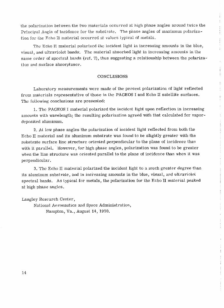
CONCLUSIONS
Laboratory measurements were made of the percent polarization of light reflected
f rom materials representative of those in the PAGEOS I and Echo I1 satell i te surfaces.
The following conclusions a r e presented:
1. The PAGEOS I material polarized the incident light upon reflection in increasing
amounts with wavelength; the resulting polarization agreed with that calculated for vapor-
deposited aluminum.
2. At low phase angles the polarization of incident light reflected from both the
Echo I1 material and its aluminum substrate was found t o be slightly greater with the
substrate surface line s t ructure oriented perpendicular t o the plane of incidence than
with it parallel. However, for high phase angles, polarization was found to be greater
when the line s t ructure was oriented parallel to the plane of incidence than when it was
perpendicular.
3. The Echo I1 material polarized the incident light t o a much greater degree than
its aluminum substrate, and in increasing amounts in the blue, visual, and ultraviolet
spectral bands. As typical for metals, the polarization for the Echo I1 material peaked
at high phase angles.
Langley Research Center,
National Aeronautics and Space Administration,
Hampton, Va., August 14, 1970.
REFERENCES
1. Bowker, David E .: PAGEOS Project - Compilation of Information for Use of
Experimeter, NASA TM X-1344, 1967.
2. Jakes, William C., Jr.: Participation of Bell Telephone Laboratories in Project
Echo and Experimental Results. NASA TN D-1127, 1961.
3. Goodyear Aerospace Corp.: Mobile 24-Inch Satellite Photometric Observatory.
NASA CR-66304, 1966.
4, Comrn. on Metric Pract.: ASTM Metric Pract ice Guide. NBS Handbook 102, U.S.
Dep. Corn., Mar. 10, 1967.
5. Ditchburn, R. W.: Light. Second ed., Interscience Publ., Inc., c.1963.
6. Teichman, Louis A.: The Fabrication and Testing of PAGEOS I. NASA TN D-4596,
1968.
7. Clemmons, Dewey L., J r . ; and Camp, John D.: Amorphous Phosphate Coatings for
Thermal Control of Echo 11. Electrochem. Technol., vol. 2 , no. 7-8, July-Bug.
1964, pp. 221-232.
8. P r i ce , Howard L.; and Pezdirtz, George F.: Mechanical Propert ies of Echo 11
Laminate. NASA TN D-2367, 1964.
9. Anon.: American Institute of Physics Handbook. Second ed., McGraw-Hill Book Co.,
Inc., c.1963.
10. Strong, John: Concepts of Classical Optics. W. H. Freeman and Co., 1958,
pp. 597-615.
11. Yakovlev, E . 8.; and Gerasimov, F. M.: Experimental Study of the Intensity Dis-
tribution in the Spectrum of Diffraction Gratings for Polarized Light. Opt.
Spectry., vol. X, no. 1, Jan. 1961, pp. 50-54.
FlRST CUSS MAlL -
TXXNICAE Ml!MUUMBUMS: Information receiving limbed dktributicm beca~w of preliminary data, security classifica- tion, sr ather reams.
C O N T R A W R BEPORTS : Scientific and tecjuucal information generated d e r a NASA contractor grant and considered an impostant contribution to existing knowledge.
SPEUPLa. PUBTJCh1[JQMS: I ~ O Y ' B E B C ~ ~ P ~ derived f m m of d u e t~ NASA activirim. PLlbliations inehde canferm'ce pr 9,
wurceMs, and s p h l bblicqpphk,
TE-OLWY m-UZAmON PUBUCATTOhTS: InPomarim can techmhgy used by NASA that may ba of gani&r interest in c~.mmercial and at& acm-aiXpi% applications. Publicatians incida Twh Briefs, T~tlrnQIogy Utilizari~m Reprts and Nma, and Techndogy 31inreys.