fy 2018-19 standard plans of - fdot. · pdf fileƂ" ø round bar 2.50" x...
TRANSCRIPT

1 8 11/01/16 515-052 PEDESTRIAN/BICYCLE RAILING (STEEL)
10/25/2017
4:1
9:4
6 P
M
RE
VISIO
N DESCRIPTION:
REVISION
LAST
ofSTANDARD PLANS
FY 2018-19 SHEETINDEX
NOTES
MEMBER DESIGNATIONOUTSIDE
DIMENSION
WALL
THICKNESS
Top Rail
Top Rail Joint/Splice Sleeves
Intermediate & Bottom Rail
Int. & Bottom Rail Post Connection Sleeve
Handrail Joint/Splice Sleeves
Handrails
Handrail Support Bar
1ƀ" NPS (Sch. 40)
Ƃ" Ø Round Bar
2.50" x 1.50"
2.00" x 2.00"
1.500"
1.900"
0.750"
0.750"
0.125"
0.145"
0.125"
0.188"
N/A
N/A
Ƃ" Ø Round Bar
TABLE 1 - RAILING MEMBERS
(1)
VariesVaries (See Details) VariesInfill Panel Members (Types 2 - 5)
Pickets (Type 1 Infill Panel)
3D VIEW OF RAILING WITH TYPE 1 - PICKET INFILL PANEL
(42" Height shown, 48" Height Similar)
2.500" 0.125"
2.875"
3.000"
0.120"
0.120"
(1)
2.50" x 1.50" 0.188"Post "B"
Post "A"
End Hoops2.875"
3.000"
0.120"
0.120"
TABLE 1 NOTES:
(1) 0.125" wall thickness permitted for rails with post spacings less than 5'-8",
except that Post Connection Sleeve must be 1Ɓ" NPS (Sch. 40).
1.315"
1.500"
0.133"
0.125"
CROSS REFERENCES: Detail “A”, Sheet 4
Detail “B”, Sheet 4
Detail “K”, Sheet 3
1" NPS (Sch. 40)
HSS 1.500 x 0.125
HSS 1.500 x 0.125
HSS 2 x 2 x ƈ
HSS 2.500 x 0.125
2ƀ" NPS (Sch. 10)
HSS 3.000 x 0.120
2ƀ" NPS (Sch. 10)
HSS 3.000 x 0.120
HSS 2ƀ x 1ƀ xƈ
HSS 2ƀ x 1ƀ xƃ
Notes:
1. Shop Drawings are required; see Specification Section 515
2. For bridge mounted railings work this Index with Index 515-051 Bridge Bicycle/Pedestrian Railing
3. Materials:
A. Pipe Rails and Pickets: ASTM A500 Grade B, C or D, or ASTM A53 Grade B for standard weight pipe (Schedule 40)
and ASTM A36 for bars.
B. Structural Tube: ASTM A500 Grade A, B, C, or D or ASTM A501
C. Steel Plate: ASTM A36 or ASTM A709 Grade 36
D. U-Channels and filler plates: ASTM A36 or ASTM A1011 (Grade 36).
E. Stainless steel (SS) screws: Type 316 or 18-8 Alloy
F. Galvanized Steel Fasteners: coated in accordance with Specification Section 962.
a. Hex Head Bolts: ASTM A 307 or ASTM F1554
1. Ɔ” diameter single bolt option, Grade 36
2. Ɗ” four bolt option, Grade 55
b. Adhesive Anchors: ASTM F1554 fully threaded rods, Grade 55
c. Hex Nuts: ASTM A563
d. Flat Washers: ASTM F436
e. Plate Washers: ASTM A36 or ASTM A706 Grade 36.
G. Shims: ASTM B209 Alloy 6061
H. Bearing Pads: ƃ” Plain, Fabric Reinforced or Fabric Laminated pads that meet the requirements of Specification Section 962 for Ancillary Structures.
4. Fabricate pickets and vertical panel elements parallel to the posts; except Type 2, 3 and 5 panel infills may be fabricated
parallel to the longitudinal grade. Maintain a maximum clear opening of 5Ɔ” for standard installations and 3Ɔ” when a
4” sphere requirement is indicated in the Data Tables.
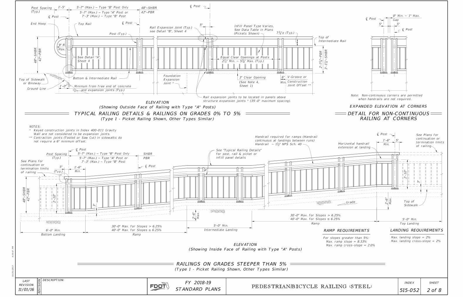
5. Maximum spacing between expansion joints is 40’-0”. Locate an Expansion Joint between the posts on either side of the Deck
Expansion Joint.
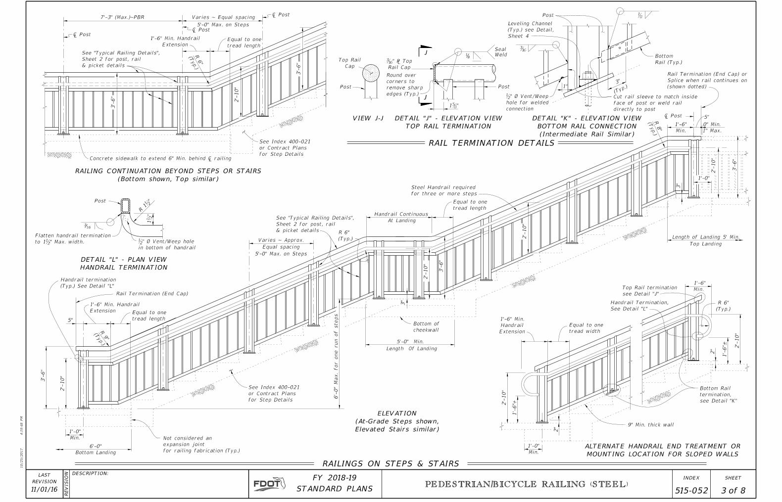
6. Field splices are similar to the Expansion Joint Detail and may be approved by the Engineer to facilitate handling; but the
top rail must be continuous across a minimum of two posts.
7. For intermediate and bottom horizontal rails, the screwed joints shown may be substituted with alternate joints shown in detail “K”.
8. Make corners and changes in tangential longitudinal alignment with a 9” bend radius or terminate adjoining sections with
mitered end sections when handrails are not required.
9. For changes in tangential longitudinal alignment greater than 45o
, position posts a maximum of 2’-0” each side of the
corner but not at the corner apex.
10. For curved longitudinal alignments, shop bend the top and bottom rails and handrails to match the alignment radius.
11. Handrails are required and must be continuous at landings for:
A. Grades Steeper than 5%,
B. Three or more steps
12. Installation: Cutting of reinforcing steel is permitted for post installed anchors.
5"
Handrail required for ramps (Handrail
continuous at landings between runs)
Handrail ~ 1ƀ" NPS Sch. 40
� Post
30'-0" Max. for Slopes > 6.25%
40'-0" Max. for Slopes ≤ 6.25%
30'-0" Max. for Slopes > 6.25%
40'-0" Max. for Slopes ≤ 6.25%
Note: Non-continuous corners are permitted
when handrails are not required.
0" Min. ~ 1" Max.
� Post
� Post
and expansion joints (Typ.)
1'-0"
� Post
� Post
� Post
DETAIL FOR NON-CONTINUOUS
RAILING AT CORNERS
RAILINGS ON GRADES STEEPER THAN 5%
Grade Top of
Sidewalk
Horizontal handrail
extension at landing
See Plans for
continuation or
termination limits
of railing
See Plans for
continuation or
termination limits
of railing
Equal Clear Openings at Posts
� Post
2'-
10"
2Ɔ" Min. ~ 5Ƃ" Max. (Typ.)
Top of
Intermediate Rail
3"
3"
3" Clear Opening
5"
5" 5"
Gap
6" V-Groove or
Min.
Foundation
Expansion
Joint *
Post (Typ.)
Top Rail
(Type 1 - Picket Railing Shown, Other Types Similar)
ELEVATION
(Showing Inside Face of Railing with Type "A" Posts)
(Type 1 - Picket Railing Shown, Other Types Similar)
1'-5"Post Spacing
(Typ.)
End Hoop
5'-7" (Max.) ~ Type "B" Post Only
9"R
Max.
5'-7" (Max.) ~ Type "B" Post Only
� Post
Post Spacing
(Typ.)
ELEVATION
(Showing Outside Face of Railing with Type "A" Posts)
Rail expansion joints to be located in panels above
structure expansion joints * (35'-0" maximum spacing).
Bottom & Intermediate Rail
5"
7Ƃ"± (Typ.)
See "Typical Railing Details"
for post, rail & picket or
infill panel details5'-7" (Max.) ~ Type "A" Post or
7'-3" (Max.) ~ Type "B" Post
5'-7" (Max.) ~ Type "A" Post or
7'-3" (Max.) ~ Type "B" Post
Infill Panel Type Varies,
See Data Table in Plans
(Pickets Shown)
See Detail "A",
Sheet 4
Rail Expansion Joint (Typ.)
see Detail "B", Sheet 4
For slopes greater than 5%:
Max. ramp slope = 8.33%
Max. ramp cross-slope = 2.0%
Max. landing slope = 2%
Max. landing cross-slope = 2%
5'-0" Min.
Top LandingRamp
2'-
6"
Max.
1'-6"
Min.
2'-
6"
Max.
5'-0" Min.
Intermediate Landing
Ramp
6'-0" Min.
Bottom Landing
(Typ.)
1'-6"
Min.
Minimum from free end of concreteGround Line
Top of Sidewalk
or Bikeway
RAMP REQUIREMENTS LANDING REQUIREMENTS
EXPANDED ELEVATION AT CORNERS
2'-
10"
TYPICAL RAILING DETAILS & RAILINGS ON GRADES 0% TO 5%
Construction
Joint Offset **
48"~
SH
BR
42"~
PB
R
SHBR
PBR
48"~
SH
BR
42"~
PB
R
48"~SHBR
42"~PBR
(See Note 4,
Sheet 1)
2'-
7Ɓ"~
PB
R
3'-
1Ɓ"~
SH
BR
NOTES:
* Keyed construction joints in Index 400-011 Gravity
Wall are not considered to be expansion joints.
** Contraction joints (Tooled or Saw Cut) in sidewalks do
not require a 6" minimum offset.
10/25/2017
4:1
9:4
7 P
M
RE
VISIO
N DESCRIPTION:
REVISION
LAST
ofSTANDARD PLANS
FY 2018-19 SHEETINDEX
11/01/16 2 8 515-052 PEDESTRIAN/BICYCLE RAILING (STEEL)
1'-0"
Min.
2"
2'-
10"
1'-
6"+
1'-6" Min.
Handrail
Extension
Equal to one
tread width
Handrail Termination,
See Detail "L"
Top Rail termination
see Detail "J"
1'-6"
Min.
R 6"
(Typ.)
2'-
10"
2"
Bottom Rail
termination,
see Detail "K"
1'-0"
2'-
10"
3'-
6"
0" Min.
1" Max.
5"
1'-6"
Min.
R 8"
(Typ.)
2'-
10"
Equal to one
tread length
Handrail Continuous
At Landing
3'-
6"
2'-
10"
Length Of Landing
Bottom of
cheekwall
R 6"
(Typ.)
6'-
0"
Max. for one run of steps
3'-
6"
6'-0"
Bottom Landing
1'-0"
Min.
R 9"
(Typ.)
1'-6" Min. Handrail
Extension
5"
Rail Termination (End Cap)
Handrail termination
(Typ.) See Detail "L"
� Post
Post
Post
Weld
Seal
ƈ" ℅ Top
Rail Cap
Post
Top Rail
Cap
Equal to one
tread length
R 6"
(Typ.)
2'-
10"
1'-6" Min. Handrail
Extension
� Post� Post
3'-
6"
Concrete sidewalk to extend 6" Min. behind � railing
Length of Landing 5' Min.
Top Landing
ELEVATION
(At-Grade Steps shown,
Elevated Stairs similar)
RAILINGS ON STEPS & STAIRS
RAILING CONTINUATION BEYOND STEPS OR STAIRS
(Bottom shown, Top similar)
VIEW J-J DETAIL "J" - ELEVATION VIEW
TOP RAIL TERMINATION
J
J
DETAIL "L" - PLAN VIEW
HANDRAIL TERMINATION
Equal to one
tread length
2'-
10"
ƃ
ƈ
Post
Bottom
Rail (Typ.)
RAIL TERMINATION DETAILS
(Typ.)
Rail Termination (End Cap) or
Splice when rail continues on
(shown dotted)3"
Leveling Channel
(Typ.) see Detail,
Sheet 4
Not considered an
expansion joint
for railing fabrication (Typ.)
3"
3"
1'-
6"±
Cut rail sleeve to match inside
face of post or weld rail
directly to post
1ƀ"
R 1
ƀ"
See "Typical Railing Details",
Sheet 2 for post, rail
& picket details
See "Typical Railing Details",
Sheet 2 for post, rail
& picket details
1"
ƀ" Ø Vent/Weep
hole for welded
connection
316
18
Flatten handrail termination
to 1ƀ" Max. width. ƀ" Ø Vent/Weep hole
in bottom of handrail
Varies ~ Equal spacing
5'-0" Max. on Steps
1ƅ"
DETAIL "K" - ELEVATION VIEW
BOTTOM RAIL CONNECTION
(Intermediate Rail Similar)
3'-
6"
� Post
5'-0" Min.
ALTERNATE HANDRAIL END TREATMENT OR
MOUNTING LOCATION FOR SLOPED WALLS
9" Min. thick wall
Varies ~ Approx.
Equal spacing
5'-0" Max. on Steps
Steel Handrail required
for three or more steps
7'-3" (Max.)~PBR
Round over
corners to
remove sharp
edges (Typ.)
See Index 400-021
or Contract Plans
for Step Details
See Index 400-021
or Contract Plans
for Step Details
10/25/2017
4:1
9:4
8 P
M
RE
VISIO
N DESCRIPTION:
REVISION
LAST
ofSTANDARD PLANS
FY 2018-19 SHEETINDEX
PEDESTRIAN/BICYCLE RAILING (STEEL)
11/01/16 3 8 515-052
Rail or Handrail
Section
Anchor Bolt
Post
� Handrail
& Bar
Post
Top Rail � Top Rail
& � Post
Post to
Base ℅
Leveling Channel
shown dashed
(see Detail)9"
Post to
Base ℅
� Base Plate &
� Anchor Bolt Hole ††
2Ɗ "±
1ƀ"
Ƃ" Ø Bar
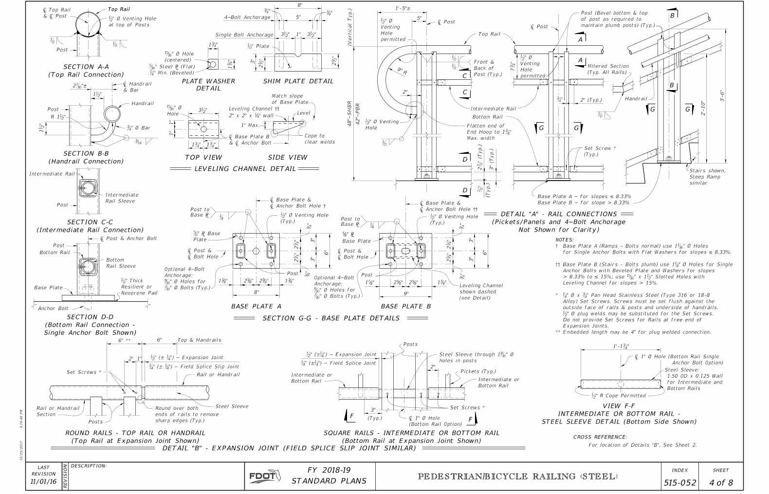
SECTION B-B
(Handrail Connection)
SECTION A-A
(Top Rail Connection)
SECTION G-G - BASE PLATE DETAILS
Ǝ" Ø Hole
(centered)
1"
6" ** Top & Handrails
Set Screws *
Ɓ" (± Ɓ") ~ Field Splice Slip Joint
ƀ" (± Ɓ") ~ Expansion Joint
1ƀ"
R 1ƀ"
ƅ" ℅ Base
Plate
Ɓ
� Base Plate &
� Anchor Bolt Hole †
� Post &
� Bolt Hole� Post &
� Bolt Hole
Intermediate Rail
� Post & Anchor Bolt
Posts
6"
DETAIL "B" - EXPANSION JOINT (FIELD SPLICE SLIP JOINT SIMILAR)
3"
ƀ" R Cope Permitted
ƀ" (±Ɓ") ~ Expansion Joint
Ɓ" (±Ɓ") ~ Field Splice Joint2"
Set Screws *
(Typ.)
Posts
FF
Rail or Handrail
ROUND RAILS - TOP RAIL OR HANDRAIL
(Top Rail at Expansion Joint Shown)
Intermediate or
Bottom Rail
� 1" Ø Hole
(Bottom Rail Option)
Intermediate or
Bottom Rail
Top Rail
CROSS REFERENCE:
"4
31
"431
1'-1Ƃ"
Ɖ" Steel ℅ (Flat)
Ɓ" Min. (Beveled)
7Ƃ"
Set Screw *
(Typ.)
ƃ
1"
1"
LEVELING CHANNEL DETAIL
3ƀ"
1Ƃ" 1Ƃ"
3" (T
yp.)
2Ɔ" (T
yp.)
Ǝ" Ø
Hole
Ƃ"
ƃ
Flatten end of
End Hoop to 1Ƃ"
Max. width
9"R
SECTION C-C
(Intermediate Rail Connection)
For location of Details "B", See Sheet 2.
Base Plate
" ℅85
Rail Sleeve
Intermediate
Rail Sleeve
Bottom
1'-5"±
Steel Sleeve VIEW F-F
INTERMEDIATE OR BOTTOM RAIL -
STEEL SLEEVE DETAIL (Bottom Side Shown)
� Post� Post
Ɓ
ƀ" Ø Venting
Hole
ƀ" Ø Venting Hole
(Typ.)ƀ" Ø Venting Hole
(Typ.)
2"
316
ƀ" Ø Venting Hole
at top of Posts
2"
Base Plate
Bottom Rail
Post
Post
Handrail
8"
Post
3"
3"
6"
3"
6"
3"
Post
Pickets (Typ.)
PLATE WASHER
DETAIL
BASE PLATE A BASE PLATE B
(Typ.)
G G
(Vertic
al
Typ.)
ƃ"
C
C
D
D
A
A
Base Plate A ~ for slopes ≤ 8.33%
Base Plate B ~ for slope > 8.33%
Top Rail
Intermediate Rail
Bottom Rail
Post (Bevel bottom & top
of post as required to
maintain plumb posts) (Typ.)
5"
Match slope
of Base Plate
Level
Cope to
clear welds
1" Max.
SIDE VIEWTOP VIEW
� Base Plate B
& � Anchor Bolt
2" (Typ.)
"831 "8
52 "852 "8
31 "871 "8
52 "852 "8
71
ƃFront &
Back of
Post (Typ.)
ƃƃ
Steel Sleeve:
1.50 OD x 0.125 Wall
for Intermediate and
Bottom Rails
SQUARE RAILS - INTERMEDIATE OR BOTTOM RAIL
(Bottom Rail at Expansion Joint Shown)
ƀ" Ø
Venting
Hole
permitted
ƀ" Ø
Venting
Hole
permitted
� 1" Ø Hole (Bottom Rail Single
Anchor Bolt Option)
NOTES:
† Base Plate A (Ramps - Bolts normal) use 1Ƈ" Ø Holes
for Single Anchor Bolts with Flat Washers for slopes ≤ 8.33%.
†† Base Plate B (Stairs - Bolts plumb) use 1Ɓ" Ø Holes for Single
Anchor Bolts with Beveled Plate and Washers for slopes
> 8.33% to ≤ 15%; use Ǝ" x 1ƀ" Slotted Holes with
Leveling Channel for slopes > 15%.
* Ɓ" Ø x Ƃ" Pan Head Stainless Steel (Type 316 or 18-8
Alloy) Set Screws. Screws must be set flush against the
outside face of rails & posts and underside of handrails.
ƀ" Ø plug welds may be substituted for the Set Screws.
Do not provide Set Screws for Rails at free end of
Expansion Joints.
** Embedded length may be 4" for plug welded connection.
DETAIL "A" - RAIL CONNECTIONS
(Pickets/Panels and 4~Bolt Anchorage
Not Shown for Clarity)
Stairs shown,
Steep Ramp
similar
ƃ
Mitered Section
(Typ. All Rails)
2'-
10"
Handrail 3'-
6"
GG
B
B
Leveling Channel ††
2" x 2" x 14" wall
ƃ" Plate
3"
3ƀ" 3ƀ"
8"
SHIM PLATE DETAIL
212"
1"
5""4
3"43
"2
12
4~Bolt Anchorage
Single Bolt Anchorage
Optional 4~Bolt
Anchorage:
Ƌ" Ø Holes for
Ɗ" Ø Bolts (Typ.)
ƃ" Thick
Resilient or
Neoprene Pad"
41
2"
41
2
"4
3
"4
3
"4
12
"4
12
"4
3"
43
Optional 4~Bolt
Anchorage:
Ƌ" Ø Holes for
Ɗ" Ø Bolts (Typ.)
SECTION D-D
(Bottom Rail Connection -
Single Anchor Bolt Shown)
holes in posts
Steel Sleeve through 1Ƌ" Ø42"~
PB
R
48"~
SH
BR
Round over both
ends of rails to remove
sharp edges (Typ.)
10/25/2017
4:1
9:4
8 P
M
RE
VISIO
N DESCRIPTION:
REVISION
LAST
ofSTANDARD PLANS
FY 2018-19 SHEETINDEX
PEDESTRIAN/BICYCLE RAILING (STEEL)
11/01/16 4 8 515-052
SECTION A-A
See Detail "1B"
See Detail "1A"
A
A
(Typ.) � Picket
� Picket
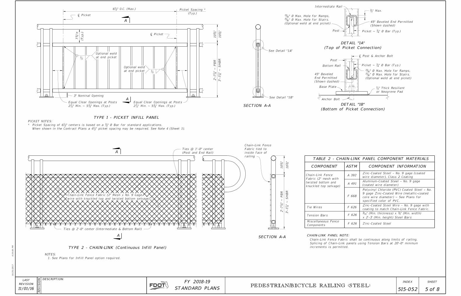
6ƀ" O.C. (Max.) Picket Spacing *
(Typ.)
Post
Ƅ" Max.
Picket ~ Ƃ" Ø Bar (Typ.)
Anchor Bolt
Base Plate
Bottom Rail
Post
ƃ" Thick Resilient
or Neoprene Pad
� Post & Anchor Bolt
Picket ~ Ƃ" Ø Bar (Typ.)
DETAIL "1A"
(Top of Picket Connection)
DETAIL "1B"
(Bottom of Picket Connection)
3" Nominal Opening
Equal Clear Openings at Posts
2Ɔ" Min. ~ 5Ƃ" Max. (Typ.)
Equal Clear Openings at Posts
2Ɔ" Min. ~ 5Ƃ" Max. (Typ.)
"±4
37
"4
310
"4
310
ƃ
ƃ
A
A SECTION A-A
Tie Wires
Tension Bars
Miscellaneous Fence
ComponentsF 626
F 626
F 626
F 668
A 491
A 392
COMPONENT COMPONENT INFORMATION
Zinc-Coated Steel
ASTM
Aluminum-Coated Steel - No. 9 gage
(coated wire diameter)
Zinc-Coated Steel - No. 9 gage (coated
wire diameter), Class 2 Coating
316" (Min. thickness) x 34" (Min. width)
x 2'-3' (Min. height) Steel Bars
Chain-Link Fence Fabric (2" Mesh x No. 9 Gage
wire with knuckled top and twisted bottom selvage)
Chain-Link Fence
Fabric tied to
inside face of
railing
Chain-Link Fence
Fabric (2" mesh with
twisted bottom and
knuckled top selvage)
Polyvinyl Chloride (PVC) Coated Steel - No.
9 gage Zinc-Coated Wire (metallic-coated
core wire diameter) ~ See Plans for
specified color of PVC.
Zinc-Coated Steel Wire - No. 9 gage with
coating to match Chain-Link Fence Fabric.
CHAIN-LINK PANEL NOTE:
Chain-Link Fence Fabric shall be continuous along limits of railing.
Splicing of Chain-Link panels using Tension Bars at 20'-0" minimum
increments is permitted.
"4
310
"4
310
Ties @ 1'-0" center
(Post and End Rail)
TABLE 2 - CHAIN-LINK PANEL COMPONENT MATERIALS
Ties @ 2'-0" center (Intermediate & Bottom Rail)
NOTES:
1. See Plans for Infill Panel option required.
TYPE 2 - CHAIN-LINK (Continuous Infill Panel)
TYPE 1 - PICKET INFILL PANEL
ƍ" Ø Max. Hole for Ramps,
Ǝ" Ø Max. Hole for Stairs.
(Optional weld at end picket)
Intermediate Rail
ƍ" Ø Max. Hole for Ramps,
Ǝ" Ø Max. Hole for Stairs.
(Optional weld at end picket)
Optional weld
at end picket
Optional weld
at end picket
(Shown dashed)
End Permitted
(Shown dashed)
2'-
7Ɓ"
~ P
BR
" ~ P
BR
41
2'-
7
3'-
1Ɓ"
~ S
HB
R
3'-
1Ɓ"
~ S
HB
R
PICKET NOTES:
* Picket Spacing of 6ƀ" centers is based on a Ƃ" Ø Bar for standard applications.
When shown in the Contract Plans a 4ƀ" picket spacing may be required. See Note 4 (Sheet 1).
10/25/2017
4:1
9:4
9 P
M
RE
VISIO
N DESCRIPTION:
REVISION
LAST
ofSTANDARD PLANS
FY 2018-19 SHEETINDEX
PEDESTRIAN/BICYCLE RAILING (STEEL)
11/01/16 5 8 515-052
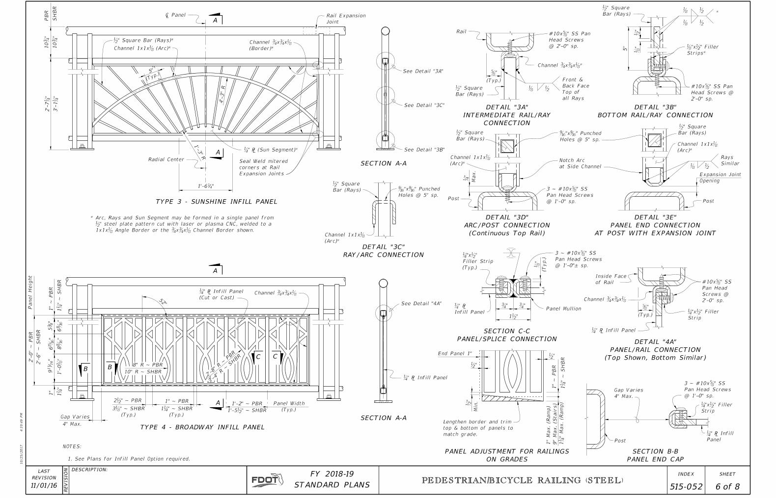
4'-
3"
R
ƀ" Square
Bar (Rays)
ƃ"
ƅ"
(Typ.)
ƀ" Square
Bar (Rays)
Ɓ" ℅ Infill Panel
ƅ"
(Typ.)
ƀ" Square
Bar (Rays) Ƌ"xƋ" Punched
Holes @ 5" sp.
ƀ" Square
Bar (Rays)
Ƌ"xƋ" Punched
Holes @ 5" sp.
Post
Notch Arc
at Side Channel
SECTION A-A
SECTION A-A
See Detail "3B"
See Detail "3C"
See Detail "3A"
A
A
(Typ.)
5"
Radial Center
DETAIL "3B"
BOTTOM RAIL/RAY CONNECTION
DETAIL "3C"
RAY/ARC CONNECTION
DETAIL "4A"
PANEL/RAIL CONNECTION
(Top Shown, Bottom Similar)
5"
Ɓ"
Max.
SECTION B-B
PANEL END CAP
Ɓ" ℅ Infill
PanelPost
Gap Varies
4" Max.
Inside Face
of Rail
Rail
DETAIL "3A"
INTERMEDIATE RAIL/RAY
CONNECTION
ƀ"
A
A
Ɓ" ℅ Infill Panel
(Cut or Cast)
4" Max.
BB
CC
"8
35
"16
11
91"
6Ǝ
"
Channel ƂxƂxƃ
Channel ƂxƂxƃ
Channel 1x1xƃ
(Arc)*
Channel 1x1xƃ
(Arc)*
� Panel
"411'-6
Ɓ"xƀ" Filler
Strip
Ɓ"xƀ" Filler
Strip
52°
(Typ.)
Panel Width
ƀ"
ƀ"
ƀ"
Min.
End Panel 1"
1'-3"
R
1"
~ P
BR
1Ɓ"
~ S
HB
R
2'-
7Ɓ"
10
Ƃ"
10
Ƃ"
3'-
1Ɓ"
2'-
0"
~ P
BR
Panel
Heig
ht
2'-
6"
~ S
HB
R
1"
~ P
BR
1Ɓ"
~ S
HB
R6ƌ
"1'-
0ƃ"
1Ɓ"
Gap Varies
2ƀ" ~ PBR 1" ~ PBR
8" R ~ PBR
TYPE 3 - SUNSHINE INFILL PANEL
TYPE 4 - BROADWAY INFILL PANEL
(Typ.)
3ƃ" ~ SHBR
(Typ.)
1Ɓ" ~ SHBR
NOTES:
1. See Plans for Infill Panel Option required.
PANEL ADJUSTMENT FOR RAILINGS
ON GRADES
1"
Max. (R
am
p)
9"
Max. (Stairs)
1Ɓ"
Max. (R
am
p)
Lengthen border and trim
top & bottom of panels to
match grade.
SECTION C-C
PANEL/SPLICE CONNECTION
Infill Panel
Ɓ" ℅Panel Mullion
Ɓ"xƀ"
Filler Strip
(Typ.)
(Typ.)
ƃ"
Ƃ"Ƃ"
1ƀ"
ƃ
ƃ
ƀ
ƀ
ƃ ƀ
Front &
Back Face
Top of
all Rays
ƀ" Square
Bar (Rays)
Post
Channel 1x1xƃ
(Arc)*
DETAIL "3D"
ARC/POST CONNECTION
(Continuous Top Rail)
DETAIL "3E"
PANEL END CONNECTION
AT POST WITH EXPANSION JOINT
ƃ ƀ
Rays
Similar
See Detail "4A"
Ɓ" ℅ Infill Panel
Opening
Expansion Joint
Rail Expansion
Joint
Seal Weld mitered
corners at Rail
Expansion Joints
ƀ" Square Bar (Rays)*
Channel 1x1xƃ (Arc)*Channel ƂxƂxƃ
(Border)*
Channel ƂxƂxƃ*
*
ƃ"xƀ" Filler
Strips*
10" R ~ SHBR
1'-5ƀ" ~ SHBR
1'-2" ~ PBR
8ƌ
"
Ɓ" ℅ (Sun Segment)*
* Arc, Rays and Sun Segment may be formed in a single panel from
ƀ" steel plate pattern cut with laser or plasma CNC, welded to a
1x1xƃ Angle Border or the ƂxƂxƃ Channel Border shown.
#10xƅ" SS Pan
Head Screws
@ 2'-0" sp.
#10xƅ" SS Pan
Head Screws @
2'-0" sp.
3 ~ #10xƅ" SS
Pan Head Screws
@ 1'-0" sp.
3 ~ #10xƅ" SS
Pan Head Screws
@ 1'-0"± sp.
#10xƅ" SS
Pan Head
Screws @
2'-0" sp.
3 ~ #10xƅ" SS
Pan Head Screws
@ 1'-0" sp.
2'-8"
R ~ P
BR
3'-4"
R ~ S
HBR
PB
R
SH
BR
10/25/2017
4:1
9:4
9 P
M
RE
VISIO
N DESCRIPTION:
REVISION
LAST
ofSTANDARD PLANS
FY 2018-19 SHEETINDEX
PEDESTRIAN/BICYCLE RAILING (STEEL)
11/01/16 6 8 515-052
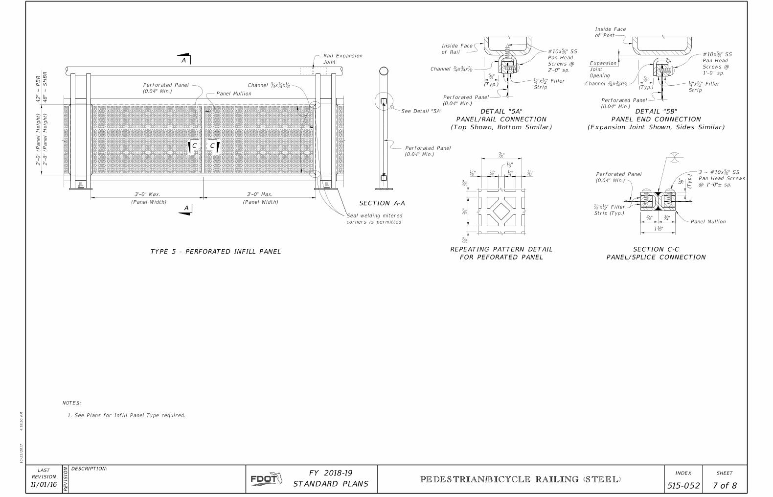
A
ASECTION A-A
See Detail "5A"
ƅ"
(Typ.)
SECTION C-C
PANEL/SPLICE CONNECTION
Inside Face
of Rail
Channel ƂxƂxƃ
Perforated Panel
(0.04" Min.)
Ɓ"xƀ" Filler
Strip
Perforated Panel
(0.04" Min.)
ƃ"
ƃ"
ƅ"
ƃ"
Ɓ" Ɓ" ƃ"
Ɔ"
ƃ"
C
Channel ƂxƂxƃPerforated Panel
(0.04" Min.)
C
REPEATING PATTERN DETAIL
FOR PEFORATED PANEL
3'-0" Max. 3'-0" Max.
(Panel Width)(Panel Width)
Panel Mullion
2'-
6" (P
anel
Heig
ht)
2'-
0" (P
anel
Heig
ht)
NOTES:
1. See Plans for Infill Panel Type required.
TYPE 5 - PERFORATED INFILL PANEL
(Typ.)
"8
1
"43"4
3
"211
Panel Mullion
Ɓ"xƀ" Filler
Strip (Typ.)
Perforated Panel
(0.04" Min.)
ƅ"
(Typ.)
Inside Face
of Post
Channel ƂxƂxƃ
Perforated Panel
(0.04" Min.)
Ɓ"xƀ" Filler
Strip
Rail Expansion
Joint
DETAIL "5A"
PANEL/RAIL CONNECTION
(Top Shown, Bottom Similar)
DETAIL "5B"
PANEL END CONNECTION
(Expansion Joint Shown, Sides Similar)
Opening
Joint
Expansion
Seal welding mitered
corners is permitted
3 ~ #10xƅ" SS
Pan Head Screws
@ 1'-0"± sp.
#10xƅ" SS
Pan Head
Screws @
1'-0" sp.
#10xƅ" SS
Pan Head
Screws @
2'-0" sp.
42"
~ P
BR
48"
~ S
HB
R
10/25/2017
4:1
9:5
0 P
M
RE
VISIO
N DESCRIPTION:
REVISION
LAST
ofSTANDARD PLANS
FY 2018-19 SHEETINDEX
PEDESTRIAN/BICYCLE RAILING (STEEL)
11/01/16 7 8 515-052
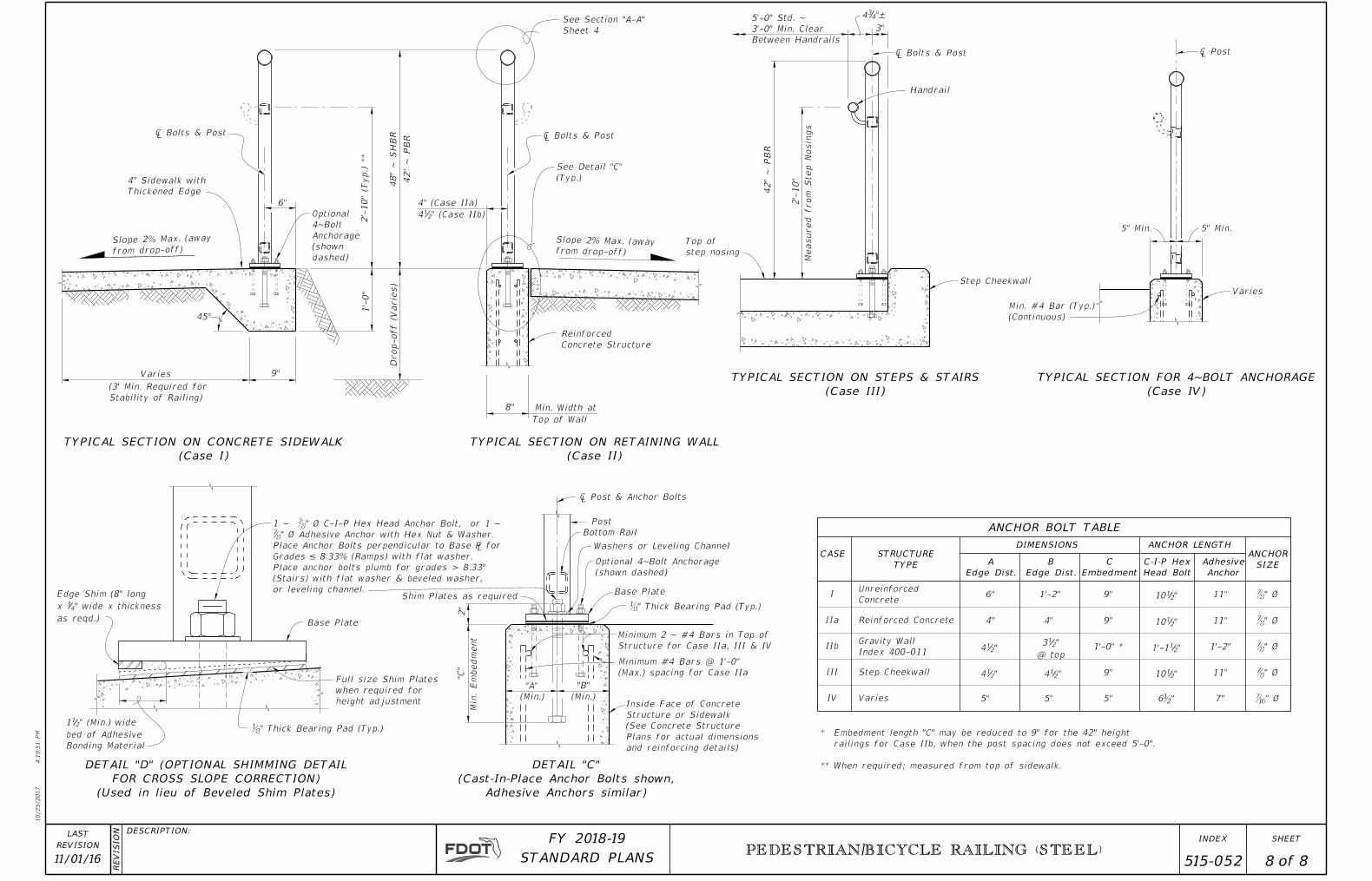
1'-0" *
� Bolts & Post
� Bolts & Post� Bolts & Post
Edge Shim (8" long
x 34" wide x thickness
as reqd.)
112" (Min.) wide
bed of Adhesive
Bonding Material
Full size Shim Plates
when required for
height adjustment
Base Plate
Shim Plates as required
� Post & Anchor Bolts
DETAIL "D" (OPTIONAL SHIMMING DETAIL
FOR CROSS SLOPE CORRECTION)
(Used in lieu of Beveled Shim Plates)
See Detail "C"
(Typ.)
See Section "A-A"
Sheet 4
Ɔ " Ø
Ɔ " Ø
Ɔ " Ø
Ɔ " Ø
5'-0" Std. ~
3'-0" Min. Clear
Between Handrails
434"±
A
Edge Dist.
B
Edge Dist.
C
Embedment
C-I-P Hex
Head Bolt
III
IIb
IIa
IUnreinforced
Concrete
Reinforced Concrete
Step Cheekwall 412"
412"
4"
6" 1'-2"
4"
312"
@ top
412" 9"
9"
9" 1012"
1012"
1'-112"
1012" 11"
1'-2"
11"
11"
Step Cheekwall
Measured fro
m Step
Nosin
gs
2'-
10"
Top of
step nosing
4" Sidewalk with
Thickened Edge
Slope 2% Max. (away
from drop-off)
6"
45°
9"1'-
0"
Drop-off (V
arie
s)
412" (Case IIb)
4" (Case IIa)
8" Min. Width at
Top of Wall
Reinforced
Concrete Structure
Slope 2% Max. (awayfrom drop-off)
Bottom Rail
Post
TYPICAL SECTION ON CONCRETE SIDEWALK
(Case I)
TYPICAL SECTION ON RETAINING WALL
(Case II)
TYPICAL SECTION ON STEPS & STAIRS
(Case III)
CASE STRUCTURE
TYPE
DIMENSIONS
ANCHOR BOLT TABLE
ANCHOR LENGTH
Adhesive
Anchor
ANCHOR
SIZE
Varies
(3' Min. Required for
Stability of Railing)
* Embedment length "C" may be reduced to 9" for the 42" height
railings for Case IIb, when the post spacing does not exceed 5'-0".
** When required; measured from top of sidewalk.
5"IV Varies 5" 5" 6ƀ" 7" Ɗ" Ø
5" Min.5" Min.
� Post
Varies
TYPICAL SECTION FOR 4~BOLT ANCHORAGE
(Case IV)
Min. #4 Bar (Typ.)
(Continuous)
Washers or Leveling Channel
DETAIL "C"
(Cast-In-Place Anchor Bolts shown,
Adhesive Anchors similar)
2"
Min.
Em
bed
ment
"C"
(Min.)
"A" "B"
(Min.)Inside Face of Concrete
Structure or Sidewalk
(See Concrete Structure
Plans for actual dimensions
and reinforcing details)
Minimum #4 Bars @ 1'-0"
(Max.) spacing for Case IIa
Base Plate
Minimum 2 ~ #4 Bars in Top of
Structure for Case IIa, III & IV
Optional
4~Bolt
Anchorage
(shown
dashed)
2'-
10" (T
yp.) **
3"
Optional 4~Bolt Anchorage
(shown dashed)
ƃ" Thick Bearing Pad (Typ.)
ƃ" Thick Bearing Pad (Typ.)
1 ~ Ɔ" Ø C-I-P Hex Head Anchor Bolt, or 1 ~
Ɔ" Ø Adhesive Anchor with Hex Nut & Washer.
Place Anchor Bolts perpendicular to Base ℅ for
Grades ≤ 8.33% (Ramps) with flat washer.
Place anchor bolts plumb for grades > 8.33°
(Stairs) with flat washer & beveled washer,
or leveling channel.
Handrail
42"
~ P
BR
48"
~ S
HB
R
42"
~ P
BR
Gravity Wall
Index 400-011
10/25/2017
4:1
9:5
1 P
M
RE
VISIO
N DESCRIPTION:
REVISION
LAST
ofSTANDARD PLANS
FY 2018-19 SHEETINDEX
PEDESTRIAN/BICYCLE RAILING (STEEL)
11/01/16 8 8 515-052