fuzzy logic based feedback control system for laser beam pointing stabilization
TRANSCRIPT
Fuzzy logic based feedback control system for laserbeam pointing stabilization
Ranjeet Singh, Kiran Patel, J. Govindarajan, and Ajai Kumar*Institute for Plasma Research, Bhat, Gandhinagar 382 428, India
*Corresponding author: [email protected]
Received 6 July 2010; accepted 12 August 2010;posted 25 August 2010 (Doc. ID 131183); published 16 September 2010
This paper reports a fuzzy logic based feedback control system for beam pointing stabilization of a high-power nanosecond Nd:YAG laser operating at 30 Hz. This is achieved by generating the correcting signalfor each consequent pulse from the error in the pointing position of the previous laser pulse. We havesuccessfully achieved a reduction of beam position fluctuation from �60 to �5:0 μrad without the focus-ing optics and �0:9 μrad with focusing optics. © 2010 Optical Society of AmericaOCIS codes: 140.3425, 140.3295.
1. Introduction
High-power lasers have very diverse scientific, com-mercial, industrial, and military applications, suchas medical treatment, atmospheric or orbital target-ing in aeronautics and aerospace, micromachining,microetching, and inspection of microlithographyfabrication. In many of these scientific applications,a highly spatially stable laser source is one of theimportant issues for successful operation of manymodern techniques, such as pulse shortening andgas-phase spectroscopy in gas-filled hollow wave-guides, femtosecond pulse shaping, and nonlinearspectroscopy with femtosecond-shaped pulses. In ad-dition to these applications, lasers have been widelyused as diagnostics tools in tokamak plasma experi-ments, such as laser blow-off, laser-induced fluores-cence, Thomson scattering, etc. In many of the abovecases, the laser beam must travel a long path toreach the experimental area, hence, even small de-viations of the adjusted beam direction may causeunpredictable distortion in the experimental data.Fluctuation in the laser beam pointing direction is animportant issue related to the laser. There are threemajor factors that contribute to pointing stability—air convection in the beam path, mechanical vibra-
tions of optical devices, and instabilities in the lasercavity. The first two can be reduced by modificationin the experimental setup. The deviation in the spa-tial beam position of pulsed system is recorded onlywhen a pulse is emitted. Therefore, using opto-electronic feedback for correcting the path of the la-ser will not be of much use. Instead, the deviation inpositions must be estimated based on the precedingpulses. An extrapolating process known as time ser-ies prediction is applied on the measured beam posi-tion, which can often be realized by filters or, oftenbetter, by some sort of logic.
The possibility of controlling the pointing stabilityof the pulsed Ti:sapphire laser system by performingtime series analysis and computer simulations on ex-perimentally measured data sets using low-pass fil-ters and artificial neural networks (NNs) has beenreported in the literature [1]. It was shown that atoptimal cutoff frequency (0:09 Hz), the simulatedprediction reduces the standard deviation of the timeseries by more than 50% in the x direction (σx) from0.577 to 0:247 μrad and in the y direction (σy) from0.880 to 0:467 μrad. In another report [2] forTi:sapphire femtosecond lasers using focusing opticsin path and without feedback control, the beam fluc-tuations were �87 μm (30 μm rms) in the horizontaldirection and �110 μm (42 μm rms) in the verticaldirection. These fluctuations were stabilized by feed-back control using proportional-integral-derivative
0003-6935/10/275143-05$15.00/0© 2010 Optical Society of America
20 September 2010 / Vol. 49, No. 27 / APPLIED OPTICS 5143

(PID) to within �4:2 μm (1:0 μm rms) and �4:7 μm(1:1 μm rms) in the horizontal and vertical direc-tions, respectively.
These methods suffer from problems such as theneed for the linearity of the control parameters,the accurate modeling of the phenomenon, a longlearning process, retuning parameters for changein the system, etc. This work tries to eliminate suchproblems by using fuzzy logic based feedback controldesign, which can inherently reduce nonlinear para-meter behavior besides being fault tolerant, robust,and smart in controlling the system. The present lo-gic configuration uses working experience for settingthe control rules. However, this holds the future pro-mise of being converted to a self-learning systemwhen the NN is also incorporated into them.
This paper describes the design and implementa-tion of a fast and multipurpose feedback systembased on fuzzy logic for the spatial stabilization[3–5] of a nanosecond laser beam. The present feed-back control system uses the fuzzy logic toolkit ofLabVIEW, piezo electrically driven mirrors, and aCCD camera. The developed feedback control systemwas implemented using fuzzy logic, as fuzzy logic isfaster and requires fewer stages than the conven-tional logic. We report the laser position feedbackcontrol system for both types of applications, wherethe laser beam is directly coupled without using fo-cusing optics and with using the focusing optics inthe laser beam path.
2. Experimental Setup
Figure 1 shows the schematic diagram of the laserbeam feedback control setup. Maintaining the spa-tial laser beam position in a particular point on aplane is achieved with the help of a position sensor,desired reference position, and amechanism for mov-ing the beam with respect to the reference position.Usually, the devices used for position sensing areposition sensitive detectors (PSDs), charge coupleddevices (CCDs), and quadrant diodes (QDs). The pre-cise steering of the laser beam is achieved with thehelp of a gimbal mirror mount fitted with high-resolution piezo actuators. At longer distances, it
is difficult to monitor the laser beam having a largediameter using PSDs or QDs due to the limited sizeof the detector area. As the requirement of the com-plete beam size is needed for the beam position cal-culation, it limits the use of the PSD as an opticalsensor. Moreover, these are small size detectorsand most often require the beam diameter of ≤1 mmto calculate the laser beam position precisely, whichis not possible without the use of focusing optics. It isobserved (discussed in the latter section) that ifbeam-focusing optics is used in the path of the beamposition measurement where the laser beam iscoupled to other systems without any focusing optics,the measured feedback results are not precise. Usageof a high-resolution CCD camera for monitoring thebeam position can solve the limitations of the PSD forlarge diameter beams. Hence, in the present setup, ahigh-resolution monochrome CCD camera is used formonitoring the beam position and a Picomotor™ forprecise steering of the gimbal mirror mount to thereference points. The CCD-based feedback controlsystem can be used for laser beam lines having focus-ing optics, too.
A. Measurement Technique
The laser beam pointing stability is described as theangular movement of the beam and is given as thecenter-of-gravity distribution of the far field beamprofiles measured in μrad. The beam pointing is nor-mally measured by tracking the centroid of the beamon a CCD camera. A typical beam position measure-ment involves tracking the centroid of the beam overseveral minutes, and the rms deviation of the drift incentroid data gives a clear picture of the laser beampointing stability. The drift of the laser beam is anentirely random phenomenon, which adds difficultyin reducing the position movement at a desiredlocation.
In the present setup, a laser beam (laser pulse en-ergy, 1:6 J; pulse width, 10 ns; pulse repetition rate,30 Hz) is steered to the target location with the helpof the gimbal mirror mount (Newport, SL15ABM), inwhich the manual micrometer screws are replacedwith Picomotor (New Focus, 8302). The Picomotor isa piezoelectric screw actuator, driven by an impulse.On receiving an impulse, the Picomotor turns the at-tached screw in small steps of ∼30 nm. Picomotorsare very useful in applications, which a require com-pact and high-resolution positioner. Among the otheradvantages of the Picomotor is the direct accessibil-ity of the screw for aligning the mirror manually, aswell as its remote operation. Moreover, these motorscan also be used in a high magnetic field environ-ment. There are some disadvantages associated withthe Picomotor, such as the motion corresponding toeach step size not being constant, as it is based onthe friction drive mechanism for turning the Picomo-tor screw. However, this drawback is not reflected inthe position measurement, as it is done using an in-dependent detector. On coupling with gimbal mount,the resolution and linear speed of the Picomotor are
Fig. 1. (Color online) Schematic arrangement of the laser beamfeedback control system.
5144 APPLIED OPTICS / Vol. 49, No. 27 / 20 September 2010
30 nm and 20 μm=s, respectively, which correspondto the angular resolution and speed of 0:30 μradand 0:2 mrad=s, respectively. A special driver unit(New Focus, 8732) is used for controlling the Picomo-tors. The input information required for the driver isthe direction of motion, speed of movement, andnumber of steps.
For measuring the laser beam position, a smallfraction of the laser beam is sampled using a wedgeplate and is allowed to fall on a fluorescent screen.The fluorescent image is tracked using a high-resolution monochrome CCD camera (Basler, A641f).This camera is triggered externally via TTL syncpulses from the laser to capture each laser pulse po-sition. Absorptive type neutral density (ND) filtersare used in the imaging path to decrease the laserbeam intensity to the required sensitivity of theCCD camera. The CCD camera is positioned in sucha manner that the image of the laser beam falls onthe required region of interest (ROI) of the image.A temperature stabilized He–Ne laser, which is col-linear with the Nd:YAG laser, is used to define theoptical axis. It is aligned to a desired position withthe help of the feedback control system, and here-after, this laser beam position is referred as “refer-ence position.” In the present configuration, theCCD camera can detect a 50 and 10 μm drift inthe beam position without and with focusing opticsin the laser beam path, respectively.
B. Image Processing
The CCD camera uses a FireWire (IEEE 1394) inter-face along with a fiber optic FireWire extender totransfer the images from the camera to the framegrabber card at 30 Hz. A program is developed usinga Vision Development Module in the LabVIEW™platform to find out the centroid of the laser beamimage acquired through the CCD camera. The pro-gram finds the centroid of the laser beam image aftersubtracting the background and thresholding. Thecentroid of the processed image gives the laser beamposition in the X and Y coordinates of the pixel. Theorigin (0, 0) of the captured image is fixed at the leftand topmost corner. The right -hand side indicatesthe X direction, and the bottom side indicates theY direction. The calculated centroid location of eachlaser beam image is then compared with the pre-viously defined reference of the laser beam, whichgives the drift in the beam position in the imageplane. These data are used for generating the feed-back control signal using the fuzzy logic controller.The program has the capability to take care of somecommon errors, such as the absence of the laser beamon the screen or the misalignment of the camera.
C. Fuzzy Logic Controller
Fuzzy logic [6] is a rule-based decision-making meth-od used for problem-solving and process control sys-tems. The basis of fuzzy logic is “fuzzy sets,” whichcontain elements with only a partial degree ofmembership. A membership function (MF) is a curve
that defines how each point in the input or outputspace is mapped to a membership value (or degreeof membership) between 0 and 1. The fuzzy logic al-gorithm involves three elements: (i) Fuzzification, (ii)inference process, and (iii) defuzzification. Fuzzifica-tion is the process of converting crisp, real-world va-lues into the degree of membership of the fuzzy set.The inference process is the evaluation of rulestrengths based on rules and inputs. The purposeof the rule base is to supply all the actions to be takenby the fuzzy controller in a particular situation.Defuzzification is a conversion process of the outputfuzzy set into numerical value.
A LabVIEW-based fuzzy logic toolkit is used fordefining input and output space, rule base and infer-ence process, and defuzzification method. The inputspace of the fuzzy logic controller accepts the beamposition data in pixels and determines the degreeto which they belong to each of the appropriate fuzzysets via membership functions. The rule base is de-fined according to the membership function. In thepresent case, the Mamdani-style fuzzy inferenceprocess is implemented with nine antecedence andconsequence membership functions. The degree ofsupport for the entire rule shapes the output fuzzyset. Defuzzification of the output sets provides thedata required by the Picomotor driver.
D. Beam Position Controls
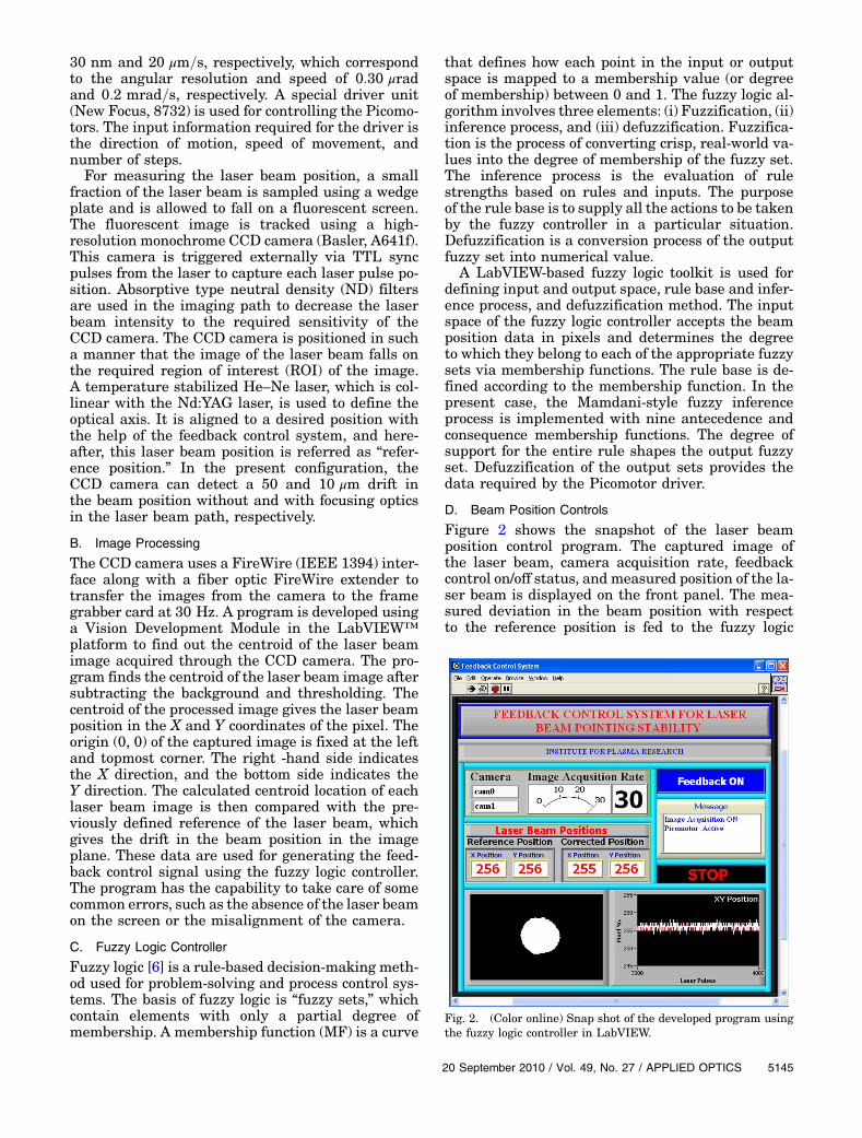
Figure 2 shows the snapshot of the laser beamposition control program. The captured image ofthe laser beam, camera acquisition rate, feedbackcontrol on/off status, and measured position of the la-ser beam is displayed on the front panel. The mea-sured deviation in the beam position with respectto the reference position is fed to the fuzzy logic
Fig. 2. (Color online) Snap shot of the developed program usingthe fuzzy logic controller in LabVIEW.
20 September 2010 / Vol. 49, No. 27 / APPLIED OPTICS 5145

controller, where its logic program calculates thenumber of required pulses, the direction of the move-ment to keep the beam-pointing stability within thelimit of tolerance using the fuzzy logic, and transmitsthe required information to the Picomotor driverthrough digital input/output (I/O). The Picomotorcan take pulses at 2 KHz, and it takes approximately7 ms to change the direction from clockwise to coun-terclockwise and vice versa. All the processes, i.e.,the capturing of the image, processing of the image,calculation of the centroid, calculation of the numberof pulses, frequency, direction, and Picomotor move-ment are completed in less than 25 ms, which is wellbefore the arrival of the next laser pulse. For higherrepetition rate laser systems, a fast frame rate cam-era and fast response Picomotor driver must be used.
3. Results and Discussion
A feedback control system, based on fuzzy logic, toimprove laser beam pointing stability is developed.The developed hardware and software is tested fora 10 m long beam path. The system can work wellwith and without focusing optics in the beam path,depending on the experimental needs. At the first in-stance, we consider the case in which the laser beamis not focused. In this case, the complete beam dia-meter is used for the calculation of the beam cen-troid, then the corresponding feedback signal tothe Picomotor driver is generated from the fuzzy lo-gic controller for improving beam pointing stability.Normally, the camera is aligned in such a mannerthat the beam falls near the reference point (256pixels in the present setup; any of the pixels canbe used). The centroid of the subsequent Nd:YAG la-ser beam pulses is computed and processed by theprogram for estimating the deviation of the laserbeam with respect to the reference point for generat-ing the feedback.
Figure 3 shows the recorded fluctuations in thebeam position with and without the feedback control.The feedback control is applied for a duration of∼1 min (2000 laser pulses) indicated by “ON” in thefigure. The fluctuation in the laser beam position inthe feedback off condition is �60 μrad (∼� 20 pixel),which reduces to�5:0 μrad (�1 pixel) when the feed-back control is on. Figure 4 shows the histogramof thebeam position along the horizontal (X axis) and verti-cal (Y axis) directions with and without the feedbackcontrol. From the figure, it is apparent that the feed-back control suppresses the fluctuation significantly.It is also observed that in the absence of the feedbackcontrol, the fluctuations aremore in the horizontal di-rection (X axis) than vertical direction (Yaxis), whichis due to the laser head design. In the laser head, twoflash lamps are oriented at an angle of 180° in the ver-tical plane. This orientation gives better thermal sta-bility in the vertical direction, resulting in lessfluctuation in the Y direction. On analyzing the ac-quired laser beam images statistically (sample size65,000), it is found that only 30% of points lie nearthe reference point (�1 pixel) when the feedback con-
trol is off, which subsequently increase to 96% on theapplication of the feedback control. As stated above,when the feedback control is applied, 96% of the laserbeampulsesare lyingwithin the tolerance of�1 pixel,where one pixel has a 50 μm spatial resolution. Thelaser beam pulses, which lie outside�1 pixel with re-spect to reference position, are due to an uneven stepsizeofPicomotor,whichvariesdependingon thedirec-tion of themovementand theactive loadon it. Furtherimprovement in the present setup is not possible be-cause of the large laser beam size and limited cameraresolution.
In the second case, in which the focusing optics areused in the beam path (e.g., in Thomson scattering,micromachining, material processing, and couplingof a high-power laser to small core diameter fiberoptic cable, etc.), it is quite evident from Fig. 5 thatthe introduction of the focusing optics in the pathsuppresses the beam fluctuations to some extent.
Fig. 3. Effect of feedback control on the laser beam fluctuation in(a) pixel number and (b) μrad as function of number of laser pulses.The applied condition is represented by “OFF” (feedback controloff) and “ON” (feedback control on).
Fig. 4. (Color online) Spread of laser beam fluctuation in the hor-izontal (X axis) and vertical (Y axis) directions with and withoutfeedback control condition is represented in histogram.
5146 APPLIED OPTICS / Vol. 49, No. 27 / 20 September 2010

However, even this magnitude of fluctuations can beproblematic in the case of high-power laser applica-tions mentioned above. Therefore, the same feedbackcontrol system with appropriate modification in thecontrol logic is applied to correct the beam positionsin this case, too. Focusing optics in the beam line hasthe advantage of using a magnifying lens for imagingthe beam spots, which thereby improves the accuracyin the position measurement from 50 to 10 μm. It isobserved that the extent of the beam position fluctua-tion reduces from �600 to �70 μm due to focusingoptics. When the feedback is applied, 99% of the laserpulses lie near the reference point with a tolerance of�1 pixel, where 1 pixel corresponds to a 10 μm spa-tial resolution. In terms of angular deviation (μrad),the beam fluctuation is reduced from �60 to�7:0 μrad (due to focusing optics) and�0:9 μrad withthe application of feedback control, which is a signif-icant improvement in the beam pointing stability.
4. Conclusion
We have developed a feedback control system basedon fuzzy logic for spatial stabilization of a high-power
nanosecond laser operating at a 30 Hz repetitionrate. On application of feedback control, laser beamposition fluctuations are reduced from �60 μrad to�5:0 μrad without focusing optics and �0:9 μradwith the use of focusing optics. The reproducibilitytest of the beam stabilization was performed on 20sets of data (each set having 60,000 data points).The average variation in the results of beam positionpointing stabilization was found to be less than 1%.The reported results for stabilization of laser beamposition fluctuations are much better than the pre-viously reported one in terms of ratio of stabilizedand unstabilized values. The developed feedbackcontrol system is reliable, simple in implementation,and cost effective. With slight modification in fuzzylogic controller, the control system can be utilizedfor various experiments. Further improvement inthe speed can be achieved by implementing the fuzzylogic and Picomotor driver in the hardware likeFPGA (Field Programmable Gate Array) and the em-bedded controller.
The authors are thankful to Y. C. Saxena, H. C.Joshi, and Jinto Thomas for fruitful discussion andcritically evaluating the manuscript.
References
1. F. Breitling, R. S. Weigel, M. C. Downer, and T. Tajima,“Laser pointing stabilization and control in the submicrora-dian regime with neural networks,” Rev. Sci. Instrum. 72,1339–1342 (2001).
2. T. Kanai, A. Suda, S. Bohman, M. Kaku, S. Yamaguchi, and K.Midorikawa, “Pointing stabilization of a high-repetition-ratehigh-power femtosecond laser for intense few-cycle pulse gen-eration,” Appl. Phys. Lett. 92, 061106 (2008).
3. I. Yamada, K. Narihara, K. Yamauchi, andH. Hayashi, “Activecontrol of laser beam direction for LHDYAG Thomson scatter-ing,” Rev. Sci. Instrum. 72, 1126–1128 (2001).
4. A. Stalmashonak, N.I Zhavoronkov, I. Volker H., Sergei Vetrov,and K. Schmid, “Spatial control of femtosecond lasersystem output with submicroradian accuracy,” Appl. Opt.45, 1271–1274 (2006).
5. L. Kral, “Automatic beam alignment system for a pulsedinfrared laser,” Rev. Sci. Instrum. 80, 013102 (2009).
6. E. Cox, The Fuzzy Systems Handbook (Academic, 1994).
Fig. 5. (Color online) Scatter plot for the laser beam fluctuationwhen focusing optics is used in the beam path. The black dark andlight dark square portions show the corrected beam position with-in limit and over shooting fluctuation of the laser beam under feed-back condition.
20 September 2010 / Vol. 49, No. 27 / APPLIED OPTICS 5147