fuzzy logic based analysis of steady state stability of a...
TRANSCRIPT
1
AMSE JOURNALS –2014-Series: ADVANCES B; Vol. 57; N° 1; pp 1-19 Submitted September 2013; Revised Dec. 26, 2013; Accepted Feb. 1, 2014
Fuzzy Logic Based Analysis of Steady State Stability of a CSI Fed
Synchronous Motor Drive System with Damper Windings Included
*Prasad Srikant, **Jha Manoj, ***M. F. Qureshi,
* Department of Electrical Engg., OPJIT , Raigarh, India
** Department of Applied Mathematics, Rungta Engg. College, Raipur, India,
***Department of Electrical Engg., Govt. Polytechnic, Dhamtari, India
([email protected], [email protected], [email protected])
Abstract
Steady state stability criteria of A.C. drives play a dominant role for making the drive
system practically successful. Generally such steady state stability analysis (SSSA) is done using
small perturbation model. This study presents a detailed steady state stability analysis (SSSA)
criterion based on small perturbation model of a fuzzy based current source inverter fed
synchronous motor (CSIFSM) drive system taking d-axis and q-axis damper winding into account
using fuzzy set theory. The modeling also clearly shows that even at no load the system satisfies
steady state stability analysis (SSSA) criterion. The current source inverter fed synchronous motor
(CSIFSM) has been treated as a five coil primitive machine model using the concept of generalized
theory of electrical machines. Using the concept of Park’s transformation the armature current in d-
q model has been represented by suitable equations as a function of armature current magnitude in
phase model (IS) and the field angle (β). As the system under consideration is basically a current
source inverter fed system, IS has been considered as a constant and as a consequence the field
angle (β) finally appears as a control variable. Finally the transfer function Δβ (s)/ΔTL(s) have been
formulated; where Δβ (s) and ΔTL (s) represent small change in transformed field angle and load
torque, respectively. A fuzzy logic system is developed for steady state stability study of CSI fed
Synchronous Motor (CSIFSM) and discussed for its better performance. The analysis concludes
that the absence of damper winding leads to instability of the machine system.
Key Words: Steady State Stability Analysis (SSSA), current source inverter fed synchronous
motor (CSIFSM)
2
1. Introduction
In this study, A.C. motor drives using inverter-fed synchronous machines are used in some
specific application areas, certain features that make them preferable to induction motor drives
(Marx et al., 2008). One of those specific examples is the accurate simultaneous speed control of a
number of motors by using synchronous motors. There are companion studies (Das and
Chattopadhyay, 2004; Yan et al., 2008) in the direction of power electronic control of synchronous
motor drive systems. Das and Chattopadhyay (2004) basically deals with the analysis of control
mechanism of a synchronous motor drive system with the help of a cycloconvertor: direct torque
control. Sayeef et al. (2008) explained the direct torque control of Permanent Magnet Synchronous
Machine Motors (PMSM). Yan et al. (2008) discussed the direct torque control of PMSM taking
the effect of saturation saliency into account. Chan et al. (2008) introduced a flux-observer method
to estimate the rotor speed of a PMSM. Fabijanski and Lagoda (2008) has been reported author
study in 2008. This study deals in fuzzy logic control of inverter fed synchronous motor based on a
simply mathematical model, algorithmic investigations of stability criteria. Using fuzzy logic
algorithm, similar work on CSI fed Synchronous Motor (CSIFSM). (Uddin and Rahman, 2007) has
been reported and the controller was found to robust for high-speed applications. Though most of
the inverters used in A.C. drive are voltage source inverters, current source inverters are also being
recognized due to simplicity, greater controllability and ease of protection. This study examines
steady state stability aspects of a C.S.I. fed synchronous machine (CSIFSM) drive system
considering the presence of damper winding on both direct and quadrature axis. There is a necessity
of providing a damper winding in the q-axis to assure the steady-state stability at no-load. Even
though the authors of the present study have used the axis model of synchronous motor for analysis
of steady state stability, the reference (Korshunov, 2009) has drawn the attention because such work
relates with the state variable model. Chattopadhyay et al. (2011) does not involve synchronous
motor as a topic of research but the main similarity lies in the fact that this study also uses Laplace
transforms as a tool for mathematical modeling using state variable approach applied to solar array
power system. According to Jazaer et al. (2011) synchronous motor can be included playing the
role of the symbol of the motor shown in the Fig.1 and 2. Babainejad and Keypour (2010) analysed
the effect of electrical parameters of an Induction Generator on the transient voltage stability of a
variable speed wind turbine system. Furthermore this study uses the torque balance equations in the
phase model which can be converted to d-q model using the well-known torque balance equation

3
i.e., Te = id Ψq.-Ψd iq. There are many representative form of transfer function in association with the
steady state stability analysis of a Current Source Inverter fed synchronous motor (CSIFSM) drive
system. Taking the practical aspect into account, the present study targets to derive an expression in
a suitable form for transfer function which is the ratio of the Laplace transfer of the small signal
version of the change in angle (β) between the field (rotor) m.m.f. axis and armature (stator) m.m.f.
axis to the Laplace transform of the small signal version of change in load torque (TL). The
objective of the study is to diagnose the fact whether the synchronous motor with damper winding
and fed through a current source inverter can sustain small perturbation in load torque or not. This
analysis has been carried out from the view point of the concept of steady state stability criteria of
an electrical drive system.
An inverter is a device that converts dc power into ac power. This can be broadly
classified into two types: Voltage Source Inverter (VSI) and Current Source Inverter (CSI). A
Voltage fed inverter (YFI) or Voltage source inverter (VSI) is one in which the de source has small
or negligible impedance. In other words, a voltage source inverter has stiff dc. Voltage source at its
input terminals. Therefore it is an adjustable frequency voltage source. A Current fed inverter (CFI)
or current source inverter (CSI) is fed with adjustable current from dc source of high impedance i.e.
form a stiff dc current source; output current waves are not affected by the load. For steady state
stability analysis (SSSA) of CSI fed Synchronous Motor (CSIFSM), the flux should be kept
constant, i.e. the air gap voltage to frequency (Elf) ratio should be kept constant. Since we vary the
frequency to control the speed, hence voltage should be varied accordingly to keep ElF ratio
constant
This paper presents an application of fuzzy logic to control the speed of a CSI fed
Synchronous Motor (CSIFSM). Based on the analysis of the CSIFSM transient response and fuzzy
logic, a fuzzy controller is developed. The fuzzy controller generates the variations of the reference
current vector of the CSIFSM speed control based on the speed error and its change. Digital
simulation results shows that the designed fuzzy speed controller realizes a good dynamic behavior
of the motor, a perfect speed tracking with no overshoot and a good rejection of impact loads
disturbance. The results of applying the fuzzy logic controller to a CSIFSM show best performances
and high robustness than those obtained by the application of a conventional controller.
The organization of this paper is as follows: in section 2, the fuzzy logic control principle is
described and used to design fuzzy logic controllers; in section 3, vector control principle for
synchronous motor drive is presented, the proposed controllers are used to control the synchronous
4
motor speed. In section 4, simulation results are given to show the effectiveness of these controllers
and finally conclusions are summarized in the last section.
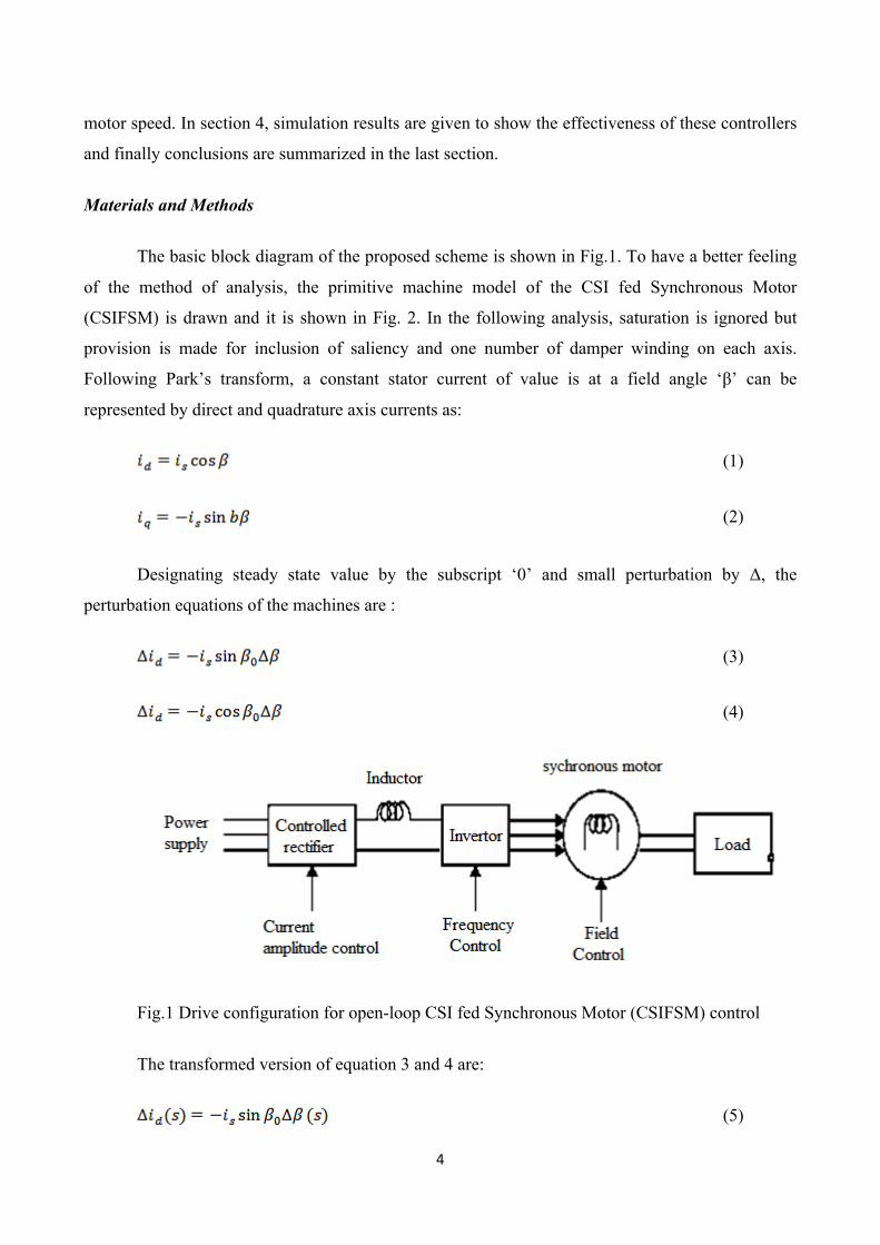
Materials and Methods
The basic block diagram of the proposed scheme is shown in Fig.1. To have a better feeling
of the method of analysis, the primitive machine model of the CSI fed Synchronous Motor
(CSIFSM) is drawn and it is shown in Fig. 2. In the following analysis, saturation is ignored but
provision is made for inclusion of saliency and one number of damper winding on each axis.
Following Park’s transform, a constant stator current of value is at a field angle ‘β’ can be
represented by direct and quadrature axis currents as:
(1)
(2)
Designating steady state value by the subscript ‘0’ and small perturbation by Δ, the
perturbation equations of the machines are :
(3)
(4)
Fig.1 Drive configuration for open-loop CSI fed Synchronous Motor (CSIFSM) control
The transformed version of equation 3 and 4 are:
(5)

5
(6)
The torque dynamic equation of a synchronous motor can be written as:
(7)
Where, ω = motor speed in mechanical rad sec-1. J = polar moment of inertia of motor and
load (combined). The small change in speed ‘ω’ equal to Δω can be related to small change in field
angle, Δβ as given by:
(8)
The negative sign in equation physically indicates a drop in speed (ω) due to increase in
field angle (β). Based on Eq. 8, the following expression can be written:
(9)
The small-perturbation model of Eq. 7 can be written as:
(10)
Combining Eq. 9 and 10, it yields:
(11)
The transformed version of Eq. 11 with initial condition relaxed comes out to be:
(12)
Incremental Torque can be re-expressed as:
(13)
Substituting the expression for ΔTe (s) from Eq. 13 in Eq. 12 we have:

6
(14)
Equation 14 gives, after manipulation, a transfer function T (s) expressed as:
(15)
Where, , , , , ,
The expression for: in 15 gives a light in the direction of analysis of steady state
stability criterion. In fact the denominator polynomial of right-hand side of eq. 15, set to zero,
becomes the characteristic equation. A Fuzzy logic Model of the characteristic equation will
ultimately lead to the status of steady state stability.
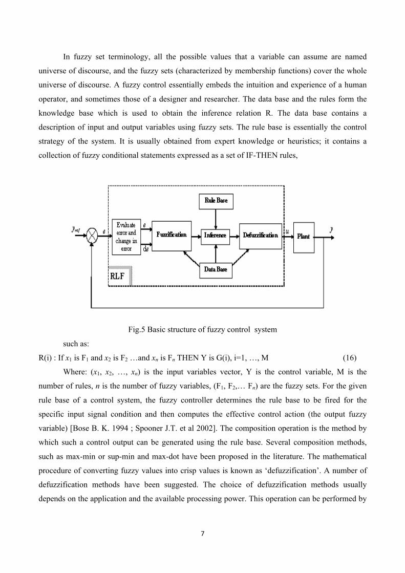
2. Fuzzy Logic Model for steady state stability analysis (SSSA) The structure of a complete fuzzy control system consists of the following main parts:
1. Fuzzification, 2.Knowledge base, 3.Inference engine, 4.Defuzzification.
Fig. (4) Shows the internal configuration of a fuzzy logic controller and Fig.5. Shows basic
structure of fuzzy control system
Fuzzy logic principle
The fuzzification module converts the crisp values of the control inputs into fuzzy values. A
fuzzy variable has values which are defined by linguistic variables (fuzzy sets or subsets) such as
low, Medium, high, big, slow… where each one is defined by a gradually varying membership
function.
Fig. 4 The internal configuration of a fuzzy logic Controller
7
In fuzzy set terminology, all the possible values that a variable can assume are named
universe of discourse, and the fuzzy sets (characterized by membership functions) cover the whole
universe of discourse. A fuzzy control essentially embeds the intuition and experience of a human
operator, and sometimes those of a designer and researcher. The data base and the rules form the
knowledge base which is used to obtain the inference relation R. The data base contains a
description of input and output variables using fuzzy sets. The rule base is essentially the control
strategy of the system. It is usually obtained from expert knowledge or heuristics; it contains a
collection of fuzzy conditional statements expressed as a set of IF-THEN rules,
Fig.5 Basic structure of fuzzy control system
such as:
R(i) : If x1 is F1 and x2 is F2 …and xn is Fn THEN Y is G(i), i=1, …, M (16)
Where: (x1, x2, …, xn) is the input variables vector, Y is the control variable, M is the
number of rules, n is the number of fuzzy variables, (F1, F2,… Fn) are the fuzzy sets. For the given
rule base of a control system, the fuzzy controller determines the rule base to be fired for the
specific input signal condition and then computes the effective control action (the output fuzzy
variable) [Bose B. K. 1994 ; Spooner J.T. et al 2002]. The composition operation is the method by
which such a control output can be generated using the rule base. Several composition methods,
such as max-min or sup-min and max-dot have been proposed in the literature. The mathematical
procedure of converting fuzzy values into crisp values is known as ‘defuzzification’. A number of
defuzzification methods have been suggested. The choice of defuzzification methods usually
depends on the application and the available processing power. This operation can be performed by

8
several methods of which center of gravity (or centroid) and height methods are common [Spooner
J.T. et al 2002; Rachid A. 1996].
The actual crisp input are approximates to the closer values of the respective universes of
discourse. Hence, the fuzzy inputs are described by singleton fuzzy sets. The elaboration of this
controller is based on the phase plan. The control rules are designed to assign a fuzzy set of the
control input u for each combination of fuzzy sets of e and Δe [Aissaoui A.G. et al. 2007]. The
performances of such controller depend on the quality of rules and the choice of the fuzzy sets that
describe number of the inputs and the output of the controller.
Fuzzy control with seven fuzzy subsets for steady state stability analysis (SSSA)
Table 1 shows one of possible control rules based on seven membership functions [Aissaoui
et al. 2011].
Table 1. Rules Base for speed control
Here NS is negative small and PS is positive small. The labels of fuzzy sets and their corresponding
membership functions are depicted in figures 6.
9
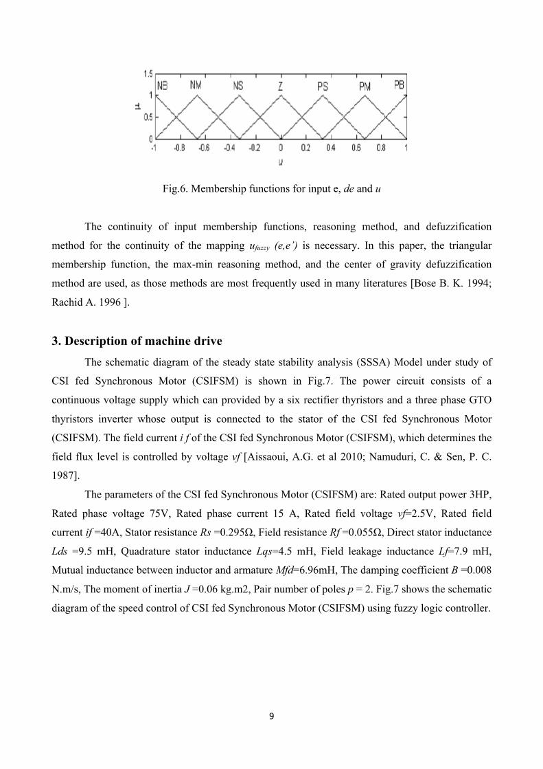
Fig.6. Membership functions for input e, de and u
The continuity of input membership functions, reasoning method, and defuzzification
method for the continuity of the mapping ufuzzy (e,e’) is necessary. In this paper, the triangular
membership function, the max-min reasoning method, and the center of gravity defuzzification
method are used, as those methods are most frequently used in many literatures [Bose B. K. 1994;
Rachid A. 1996 ].
3. Description of machine drive The schematic diagram of the steady state stability analysis (SSSA) Model under study of
CSI fed Synchronous Motor (CSIFSM) is shown in Fig.7. The power circuit consists of a
continuous voltage supply which can provided by a six rectifier thyristors and a three phase GTO
thyristors inverter whose output is connected to the stator of the CSI fed Synchronous Motor
(CSIFSM). The field current i f of the CSI fed Synchronous Motor (CSIFSM), which determines the
field flux level is controlled by voltage vf [Aissaoui, A.G. et al 2010; Namuduri, C. & Sen, P. C.
1987].
The parameters of the CSI fed Synchronous Motor (CSIFSM) are: Rated output power 3HP,
Rated phase voltage 75V, Rated phase current 15 A, Rated field voltage vf=2.5V, Rated field
current if =40A, Stator resistance Rs =0.295Ω, Field resistance Rf =0.055Ω, Direct stator inductance
Lds =9.5 mH, Quadrature stator inductance Lqs=4.5 mH, Field leakage inductance Lf=7.9 mH,
Mutual inductance between inductor and armature Mfd=6.96mH, The damping coefficient B =0.008
N.m/s, The moment of inertia J =0.06 kg.m2, Pair number of poles p = 2. Fig.7 shows the schematic
diagram of the speed control of CSI fed Synchronous Motor (CSIFSM) using fuzzy logic controller.

10
Fig.7. System Configuration of Field-Oriented CSI fed Synchronous Motor (CSIFSM) Control.
4. Steady State Stability Analysis (SSSA) of CSI fed Synchronous Motor
(CSIFSM) This section deals with steady state analysis of PWM signal fed, synchronous motor. Using
fuzzy logic theory considering mathematical model, performance characteristics of the drive under
steady state are, obtained for comparison, corresponding performance. Characteristics of the motor
when fed from sinusoidal supply are also presented.
Equivalent circuit approach for predetermination of the steady state performance of the
synchronous motor is well suited, when the input voltage is sinusoidal. However, when the motor
voltage is non-sinusoidal, as in the case of present drive, it is more convenient to Work out the
performance in time domain on instantaneous basis. The modulating wave and a carrier wave
voltage of a particular carrier ratio are generated and the signals obtained by comparing them are
used to trigger various PWM inverter devices. The PWM voltage is considered as forcing function
to the coupled circuit Model of induction motor and waveforms of the motor current are obtained m
time domain. This requires the mathematical model of the drive to be solved through numerical
techniques. From the initial standstill conditions the motor is allowed to build up under a given load
torque until steady state is reached. The steady state is identified when the motor current waveform
successively exhibits identical cycles. The voltage-current waveforms are then used to compute the
steady-state performance in time-domain. This analysis is carried out at a selected frequency of 50
Hz and at no and full load condition.
Stability Control System Structure
The general stability model of the proposed CSI fed Synchronous Motor (CSIFSM) drive is
shown in Fig. 7. Unlike the fixed dc-link current scheme, this scheme varies the dc-link current, in
11
order to keep the CSI modulation index constant in steady state. The global control strategy is
composed of two main control loops. The first control loop is the motor speed control (ɷm) based
on a slip speed regulator, which sets the slip speed reference (ɷs1) . The synchronous speed (ɷms) ,
obtained by adding the actual speed and the slip speed, determines the inverter frequency (fl) . The
motor voltage reference signal (Vl,ref) is constructed from the frequency using a function generator,
which ensures a nearly constant flux operation. Finally, the voltage controller and the space-vector
modulator produce the switching pattern ([Si]) based on the difference between the sine voltage
reference waveforms (vl,ref) and the sampled load voltage waveforms (vl) . This feedback scheme
ensures that the CSI gating pattern is modified on-line, so as to force the output voltage (vl) to track
the reference (vl,ref) , thereby resulting in a fast dynamic response, with rise times in the range of
the sampling period( tsample) of the space-vector technique. The second control loop is the PWM CSI
modulation index Loop (mi) . The main function of this slower loop is to set online the dc-link
current reference (idc,ref) in such a way that the steady-state PWM CSI modulation index remains
equal to the reference (mi,ref). It is well known that a synchronous motor is unable to self-start when
supplied with a constant frequency source. The starting torque of the CSI fed Synchronous Motor
(CSIFSM) used in this research is provided by a rotor squirrel cage winding. The starting process of
the CSI fed Synchronous Motor (CSIFSM) drive can be considered as a superposition of two
operating modes, namely: 1) unsymmetrical asynchronous motor mode and 2) magnet-excited
asynchronous generator mode.
Controller Models
1) Fuzzy Speed Controller: The block diagram of the FLC, which is utilized as a speed
controller in this work, is shown in Fig.8. In this normalized FLC, the present sample of the
speed error Δω(n) and the present sample of the change of speed error Δe(n) are the inputs.
The present sample of the q-axis command current i∗ q(n) is the output. Six rules were used
for the proposed FLC. Various scaling factors (kω, ke, and ki) for the FLC were tuned by
trial and error to get an optimum drive performance. The FLC was normalized so that it can
be used for different ratings and different types of motors.
2) Current Controller: Two independent sinusoidal band hysteresis current controllers are
used to force phases “a” and “b” currents to follow their commands. These commands are
generated from the vector control and speed control loops. The outputs of the controllers are
in the form of four logics. Those logics are used to switch ON and OFF the inverter power
switches. For the proposed control scheme, the d-axis component of the stator current id is
set to zero in order to control the motor up to the rated speed.
12
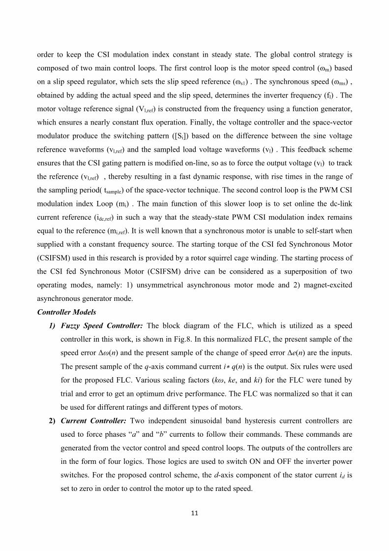
Fig.8. Fuzzy speed controller Construction
5. System Equations under Steady State In case of sinusoidal input to the motor, motor voltages and currents attain steady ac values
under steady state. When referred to synchronously rotating d-q reference frame they appear to be
dc quantities and their time derivative becomes zero. However in case of PWM inverter fed
induction motor drive the input voltage is non-sinusoidal and therefore for steady state. The
dynamic equations of the motor that are nonlinear may be solved by numerical analysis method to
get steady state currents.
Digital Simulation
The dynamic state of the induction motor can be represented by the voltage-current relations
in the motor and may be expressed in the following form
[V] = [R] [i) + l/w[X] [pi] (17)
Or
P[i] = w[-[X] -I [R] [i) + [xrl [V] (18)
Where [V] is the voltage vector,[i] is the current vector,[R] is the impedance matrix free of p terms
, (19)
Rewriting above equation as:
P(wr)= 0.5(Te-TL)/H (20)
The equation 20 can be efficiently solved on a digital computer using numerical integration
technique. Fourth order Runge-Kutta method of numerical integration is adopted here. The accuracy
of integration depends on the integration interval; smaller the interval, greater is the accuracy. A
step interval of 0.000015 second is selected in this work.
The computation process adopted in present work has been illustrated through flow charts
shown in present Fig. 9. It begins by taking initial values of rotor speed and machine phase currents
and hence ids, iqs, idr, iqr as zero. The value of step length, base, frequency, operating frequency,
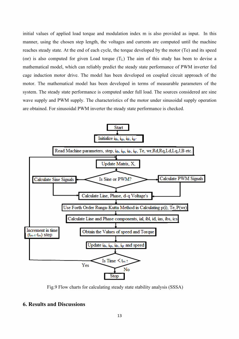
13
initial values of applied load torque and modulation index m is also provided as input. In this
manner, using the chosen step length, the voltages and currents are computed until the machine
reaches steady state. At the end of each cycle, the torque developed by the motor (Te) and its speed
(ɷr) is also computed for given Load torque (TL) The aim of this study has been to devise a
mathematical model, which can reliably predict the steady state performance of PWM inverter fed
cage induction motor drive. The model has been developed on coupled circuit approach of the
motor. The mathematical model has been developed in terms of measurable parameters of the
system. The steady state performance is computed under full load. The sources considered are sine
wave supply and PWM supply. The characteristics of the motor under sinusoidal supply operation
are obtained. For sinusoidal PWM inverter the steady state performance is checked.
Fig.9 Flow charts for calculating steady state stability analysis (SSSA)
6. Results and Discussions
14
The performances of the proposed FLC-based CSI fed Synchronous Motor (CSIFSM) have
been investigated extensively both in simulation and experiment at different dynamic operating
conditions. Sample results are presented below. Fig.10 shows the starting responses of the proposed
CSI fed Synchronous Motor (CSIFSM) drive in simulation. It is seen in Fig. 10(a) and the
effectiveness of the FLC is proven by no overshoot, no undershoot, and zero steady-state error of
the speed response. It is also seen in Fig. 10 that the steady-state phase currents, its harmonic
distortion, and the torque response of the proposed CSI fed Synchronous Motor (CSIFSM) drive are
also comparable to those of the conventional drive. The torque ripple is a little bit higher in the
proposed inverter but still in the acceptable range. The robustness of the proposed FLC-based CSI
fed Synchronous Motor (CSIFSM) drive is also verified in simulation for a sudden change in
command speed, and for a change in load, which are shown in Fig.11. In Fig. 11, the motor was
initially loaded at 0.55 N · m and at t = 0.32 s, the load was suddenly increased to 2.1 N · m, and at t
= 0.61 s, the load was again decreased back to 0.52 N · m. It is evident in Fig. 11(b) that there is a
steady-state speed error for the light-load conditions. This is probably because of too much control
action of the FLC, as the control action for the FLC was designed for the rated-load condition.
However, the steady-state error is almost negligible. The performance of the proposed drive is also
tested for the speed reversal case, which is shown in Fig. 12. It is shown that the drive can
successfully reverse the speed almost accurately and quickly. The experimental starting responses
including speed phase current ia, steady-state currents ia, ib and ia, ic, and the harmonic spectrum of
ia at rated speed are shown in Fig. 12. Fig. 12(a) shows that the actual speed of the proposed drive
is following the command speed without steady-state error, which, in turn, validates the simulation
results. For safe operation, the voltage was applied to the inverter as quickly as possible through
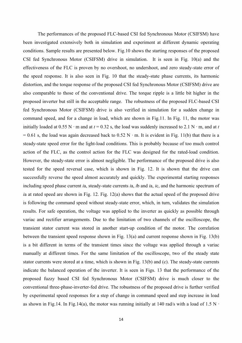
variac and rectifier arrangements. Due to the limitation of two channels of the oscilloscope, the
transient stator current was stored in another start-up condition of the motor. The correlation
between the transient speed response shown in Fig. 13(a) and current response shown in Fig. 13(b)
is a bit different in terms of the transient times since the voltage was applied through a variac
manually at different times. For the same limitation of the oscilloscope, two of the steady state
stator currents were stored at a time, which is shown in Fig. 13(b) and (c). The steady-state currents
indicate the balanced operation of the inverter. It is seen in Figs. 13 that the performance of the
proposed fuzzy based CSI fed Synchronous Motor (CSIFSM) drive is much closer to the
conventional three-phase-inverter-fed drive. The robustness of the proposed drive is further verified
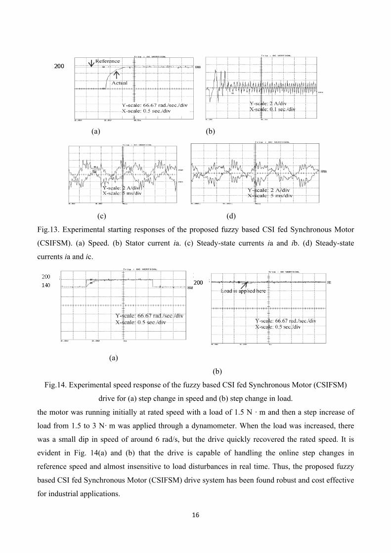
by experimental speed responses for a step of change in command speed and step increase in load
as shown in Fig.14. In Fig.14(a), the motor was running initially at 140 rad/s with a load of 1.5 N ·

15
m and then an online step increase of reference speed from 140 to 200 rad/s was applied. In Fig.14
(b),
(a) Speed (b)Developed Torque (c) Steady-state three-phase currents
Fig.10. Simulation starting responses of the proposed Fuzzy based CSI fed Synchronous Motor
(CSIFSM) drive at rated speed and rated load conditions.
(a) Speed (b) Speed error. (c) Stator current ia.
Fig.11. Simulation responses of the fuzzy based CSI fed Synchronous Motor (CSIFSM) drive for a
step change in load..
Fig.12. Simulated speed response of the proposed fuzzy based CSI fed Synchronous Motor
(CSIFSM) drive for speed reversal of command speed.
16
(a) (b)
(c) (d)
Fig.13. Experimental starting responses of the proposed fuzzy based CSI fed Synchronous Motor
(CSIFSM). (a) Speed. (b) Stator current ia. (c) Steady-state currents ia and ib. (d) Steady-state
currents ia and ic.
(a)
(b)
Fig.14. Experimental speed response of the fuzzy based CSI fed Synchronous Motor (CSIFSM)
drive for (a) step change in speed and (b) step change in load.
the motor was running initially at rated speed with a load of 1.5 N · m and then a step increase of
load from 1.5 to 3 N· m was applied through a dynamometer. When the load was increased, there
was a small dip in speed of around 6 rad/s, but the drive quickly recovered the rated speed. It is
evident in Fig. 14(a) and (b) that the drive is capable of handling the online step changes in
reference speed and almost insensitive to load disturbances in real time. Thus, the proposed fuzzy
based CSI fed Synchronous Motor (CSIFSM) drive system has been found robust and cost effective
for industrial applications.
17
7. Conclusion A CSI fed Synchronous Motor (CSIFSM) drive incorporating an FLC has been developed
and simulated. The proposed CSI fed Synchronous Motor (CSIFSM) drive found to be improved
steady state stability. The incorporation of FLC as a speed controller enhances the robustness of the
drive. In order to verify the robustness of the proposed approach, the performances of the proposed
FLC-based CSI fed Synchronous Motor (CSIFSM) drive have been investigated at different
operating conditions. A comparison of performances for the proposed fuzzy based CSI fed
Synchronous Motor (CSIFSM) motor drive with a conventional drive has also been made in terms
of the stator current and speed response under identical operating conditions. The proposed fuzzy
based CSI fed Synchronous Motor (CSIFSM) drive has been found robust and acceptable for high-
performance industrial variable speed- drive applications considering its high steady state stability
and other inherent advantageous features. The simulation results show that the proposed FLC-based
CSI fed Synchronous Motor (CSIFSM) is superior to conventional system in robustness and in
tracking precision. The simulation study indicates clearly the superior performance of FLC, because
it is adaptive in nature. It appears from the response properties that it has a high performance in
presence of the uncertain plant parameters and load disturbances. It is used to control system with
unknown model. The steady state stability analysis (SSSA) of CSI fed Synchronous Motor
(CSIFSM) by FLC gives fast dynamic response with no overshoot and negligible steady-state error.
Reference 1. S. Babainejad, and R. Keypour, 2010. “Analysis of transient voltage stability of a variable
speed wind turbine with doubly fed induction generator affected by different electrical
parameters of induction generator”. Trends Applied Sci. Res., 5: pp. 267-278.
2. T.F. Chan,W. Wang, P. Borsje, Y.K. Wong and S.L. Ho, 2008. “Sensorless permanent-
magnet synchronous motor drive using a reduced-order rotor flux observer”. IET Electric
Power Applications, Volume 2, Issue 2, March 2008, pp. 88 – 98.
3. P. Fabijanski and R. Lagoda, 2008. “A very simple fuzzy control system for inverter fed
synchronous motor”. Proceedings of the 13th Power Electronics Motion Control
Conference, Sept. 1-3, Poznan, Poland, pp. 1040-1043.
4. N. Ghorab, O. Ghorab and N.E. Debbache, 2007. “Real time dynamic simulation of
retrofitted turbo generator in matlab/ simulink environment”. J. Applied Sci.,Year
2007,Vol.7,Issue 20, pp. 3119-3122.
18
5. K. Kondo and K. Matsuoka, 2007. “Stability analysis of permanent magnet synchronous
motors for railway vehicle traction in a sudden line voltage change”. Proceedings of the 27th
Annual Conference of the Industrial Electronics Society, Nov. 29-Dec. 2, Denever, CO, pp:
1445-1450.
6. A.I. Korshunov (2009) “Analysis of the static stability of a synchronous motor with
permanent magnets by the classical method”. Russ. Electr. Eng., Vol.80, No. 2, pp. 81-85.
7. D. Marx, S. Pierfederici and B. Davat (2008) “Nonlinear control of an inverter motor drive
system with input filter-large signal analysis of the DC-link voltage stability”. Proceedings
of the Power Electronics Specialists Conference, June 15-19, Rhodes, USA, pp: 498-498.
8. S. Najafi and N.C. Kar (2007). “Effect of short-circuit voltage profile on the transient
performance of saturated permanent magnet synchronous motors”. Proceedings of the
Power Engineering Society General Meeting, June 24-28, Tampa, FL, pp: 1-6.
9. S. Sayeef, G. Foo and M.F. Rahman (2008) “Rotor position and speed estimation of a
variable structure direct torque controlled IPM synchronous motor drive at very low
speeds”. Proceedings of the Australian Universities Power Engineering Conference, Dec.
14-17, Sydney, NSW, pp.1-6.
10. B. Sergelen, (2007) “Mathematical model of salient pole synchronous motors supplied by a
frequency converter”. Proceedings of the International Forum on Strategic Technology, Oct.
3-6,Ulaanbaatar, pp:390-390.
11. G.R. Slemon, S.B. Dewan and J.W.A. Wilson, (1974) “Synchronous motor drive with
current-source inverter”. IEEE Trans. Ind. Appl., Vol. 10, Issue 3, pp. 412-416.
12. S. Tanneru, J. Mitra, Y.J. Patil and S.J. Ranade, (2007) “Effect of large induction motors on
the transient stability of power systems”. Proceedings of the 39th North American Power
Symposium, Sept. 30- Oct. 2., Las Crucess, NM, pp. 223-228.
13. M.N. Uddin and M.A. Rahman, (2007) “High-speed control of ipmsm drives using
improved fuzzy logic algorithms”. IEEE Trans. Ind. Electron., Vol. 54, Issue 4, pp. 190-199.
14. Y. Yan, J.G. Zhu and Y.G. Guo, (2008) “Initial rotor position estimation and sensorless
direct torque control of surface-mounted permanent magnet synchronous motors considering
saturation saliency”. IET Electr. Power Appl., Vol. 2, Issue 1, pp. 42-48.
15. H. Zayandehroodi, A. Mohamed, H. Shareef and M. Mohammadjafari, (2010) “Automated
fault location in a power system with distributed generations using radial basis function
neural networks”. J. Applied Sci., 10: 3032-3041.
16. A.G. Aissaoui, (2007) “The use of neural networks and fuzzy logic for control of
synchronous machine”, Phd thesis, University Djilali Liabes of Sidi Bel Abbes, Algeria.
19
17. A.G. Aissaoui, M. Abid, H. Abid, A. Tahour & A.K. Zeblah, (2007) “A Fuzzy Logic
Controller For Synchronous Machine”, Journal of electrical engineering, Vol. 58, No. 5, pp.
285–290.
18. A.G. Aissaoui, M. Abid, H. Abid, A. Tahour and A. C. Megherbi (2010) “A Fuzzy Logic
And Variable Structure Control For Permanent Magnet Synchronous Motors” International
Journal Of Systems Control (Ijsc), Vol.1, Issue 1, pp. 13-21.
19. A.G. Aissaoui, A. Tahour, N. Essenbouli, F. Nollet, M. Abid & M.I. Chergui, (2011) “A
Fuzzy-PI control To Extract An Optimal Power From Wind Turbine”, Global Conference on
Renewables and Energy Efficiency for Desert Regions and Exibition: gcreeder 2011,
Amman-Jordan, April 26th – 28th 2011.
---------------------------