futaba 8fg(s)- supplementary notes
TRANSCRIPT

1
FUTABA 8FG(S)- SUPPLEMENTARY NOTES
MALCOLM HOLT AUGUST 2010
CONTENTS
INTRODUCTION 2 TOUCH SENSOR OPERATION 2 MENUS 2 TIMERS 3 POWER MODE 3 SYSTEM MENU TRAINER 3 DISPLAY 4 USER NAME 5 SOUND 5 H/W SETTING 5 START SELECT 6 INFO 7 LINKAGE MENU SERVO MONITOR 7 MODEL SELECT 7 MODEL TYPE 7 FREQUENCY 8 FUNCTION 8 SUB TRIM 10 REVERSE 11 FAIL SAFE 11 END POINT 12 THROTTLE CUT 13 IDLE DOWN 13 T1 – T4 SET 13 WARNING 14 DATA RESET 14
MODEL MENU CONDITION 15 DUAL RATE 17 PROG MIX 20 PITCH CURVE 25 THROTTLE CURVE 25 THROTTLE DELAY 29 AILERON DIFFERENTIAL 29 FLAP SET 30 AILERON TO CAMBER FLAP MIX 32 AILERON TO BRAKE FLAP MIX 32 AILERON TO RUDDER MIX 32 RUDDER TO AILERON MIX 32 CAMBER MIX 33 ELEVATOR TO CAMBER MIX 34 CAMBER FLAP TO ELEVATOR MIX 34 BUTTERFLY 34 TRIM MIX 38 AIRBRAKE 39 V-TAIL 39 AILEVATOR 39 WINGLET 40 MOTOR 40 RUDDER TO ELEVATOR MIX 41 SNAP ROLL 41 VIRTUAL CHANNELS 42

2
INTRODUCTION Malcolm Holt
The Futaba 8FG(S) offers a large range of useful features and can be programmed with great flexibility through a very clear interface. Unfortunately the instruction manual does not do it justice. It is very good on “How” but less so on “Why”. On almost every page is a detailed list of the sequence of inputs needed to set up a particular feature but there is almost no explanation of the purpose of each input. The only way to find out is to try it and see. While this is an excellent way of gaining a real understanding of a new piece of technology it can be very time consuming and you are sometimes left with the feeling that you are still missing the point.
At an early stage I decided to keep brief notes of my findings as an aide-memoire when I need to use a particular feature in the future. If some of the notes set out below can be of use to others then that is a bonus but please note the following. They are not a detailed user guide but merely a list of supplementary notes which need to be read in conjunction with the manual. I have kept them in the same order as the manual for easy cross-reference and provided more detailed explanation of the more commonly used features. Owners of the original 8FG might like to download the manual for the 8FG Super as it includes instructions for features added in the software upgrades.
www.futaba-rc.com/downloads/manuals.html
There may be instances where I have misunderstood and there are certainly some where I am still puzzled. If the reader can shed any light in these cases I would welcome any feedback.
The notes refer only to fixed wing craft as I do not fly helicopters and are based on software version 4.1 (upgrade released for the 8FG in September 2011). There are no notes on Gyro or Fuel Mix as I have no experience of these.
TOUCH SENSOR OPERATION Malcolm Holt
The instructions are thorough and you quickly get the hang of it. I found it helpful to set up a dummy model named Tx Test and to work through the menus entering values and checking their effects on the very useful servo monitor.
Not that it matters, but has anyone worked out why the S1 button is so named?
MENUS Malcolm Holt
I struggled at first trying to work out the exact difference between the Linkage and Model menus as some functions would appear to fit in either. In the end I decided that it doesn’t matter as you quickly learn where to find things.

3
The Linkage Menu is mainly used for selecting transmitter controls and for the initial installation and adjustment of the servos. As such it provides a useful checklist when setting up a new model.
The Model Menu is more concerned with programming mixes and adjusting settings to improve the model’s performance and make it easier to control.
Software Version 3.0 added a User menu in which the user can store frequently used functions for easy access. For those without an 8FG SUPER Manual you can access it as follows. At the Home screen tap S1 once. A dashed line is highlighted. Tap return, scroll to the function required and tap return to add it to the menu. Further functions can be added in the same way by scrolling to the dashed line and tapping return. To delete an individual item, highlight it and then hold Return for one second. Changing the model type or re-setting the model data will clear the whole list. The User Menu only applies to the currently selected model.
TIMERS Malcolm Holt
If you tend to forget to start your flight timer, set one of the up/down timers to operate from the throttle stick with the switch on point just above the idle setting.
Note that the Mode option since Version 3.0 allows the setting of Hour : Minute timers.
POWER MODE Malcolm Holt
This is primarily used for range checking but you can also use it to turn off the RF so you can tinker with the programming at home for hours without irradiating yourself and everything around you.
SYSTEM MENU
TRAINER Malcolm Holt
Each channel can be set to one of four modes: - OFF, NORM, MIX and FUNC.
Page 42 of the manual states “if MIX or FUNC mode is turned on, the Instructor can make corrections while the student has control.” This seems to be incorrect. Dual control only works on channels which have been set to MIX.
If you are programming the 8FG for training note that you can only use the servo monitor to check the effects of your inputs by connecting the student transmitter. Until this is done the trainer remains inactive. This is a safety feature. If your transmitter is programmed for training and you accidently operate the trainer switch in flight you will still retain control unless a student transmitter is connected.
4
When a channel is set to NORM mode, and the trainer switch is held on, the model will respond to any settings in the student transmitter and ignore any on the 8FG master. For example, if the student transmitter has an aileron/rudder mix set then both controls will move when the aileron stick is operated even if aileron/rudder mix is not set on the 8FG master transmitter.
When a channel is set to FUNC mode the student transmitter should be reset to its default mode. When the trainer switch is held on, the model will respond to the control sticks on the student transmitter but will incorporate any settings programmed into the 8FG master. For example, program the 8FG in Glider mode with butterfly braking. Now go to screen 3 of the Trainer set up and assign V2 BFLY to FUNC mode on student channel 3. Go to screen 4 and change INHibited to ACTive. Now, when the trainer switch is held on, the throttle stick on the student transmitter will activate butterfly braking. Thus, even a very basic student transmitter can make use of the powerful programming features of the 8FG.
MIX mode operates in the same way as FUNC mode except that, when the trainer switch is held on, the model responds to both the master and student transmitters simultaneously giving full dual-control. If, for example, the rudder sticks are pushed 25% right on both transmitters the two inputs will combine and the rudder will deflect 50% to the right. Once the combined input reaches 100% further inputs have no effect to prevent damage to linkages. If the transmitter sticks are simultaneously pushed in opposite directions the servo will again adopt the position given by the combined inputs. So, if the student inputs full right and the instructor inputs full left, the rudder will be centred. When setting the trainer in MIX mode the % rate for the student can also be set. If this was set to 60% for example it would make the model less sensitive for the student but would also allow the teacher to override any incorrect student input. e.g. Student full right and teacher full left gives 40% left control movement.
It is important to remember that each channel can be assigned to any trainer mode but that any which is not assigned will still be operated by the master transmitter even when the trainer switch is held on. For example, if you have a model with two aileron servos you can assign Channel 1 Aileron to NORM trainer mode. As long as the student’s transmitter is set up to work with two servos the student will have full control of ailerons when the trainer switch is held on. However, if you move the aileron stick on the master transmitter at the same time, one of the ailerons will be moved by it. To prevent this you need to set the second aileron channel (usually Ch 6) to NORM at the Trainer setup screen as well.
DISPLAY Malcolm Holt
This is straightforward. Presumably there are implications for battery life and screen-burn so it seems best to stick to the defaults where possible.

5
USER NAME Malcolm Holt
Straightforward
SOUND
Version 3.0 introduced provision to turn off sounds and version 4.1 allows the user to set the voltage at which the low battery alarm will sound. The release notes suggest the following settings. 6-cell NiCd or MiMh : 6.8 volts (Standard battery). 2-cell LiFe : 6.0 to 6.2 volts. 2-cell LiPo : 7.2 to 7.4 volts.
Turning off Warnings will disable the sounds of mixer warnings, the alarm when the transmitter has been inactive for 30 minutes and also the LOW BATTERY ALARM. This final item appears to be a recipe for disaster.
Turning off Other Sound will disable the beeps when programming.
H/W SETTING Malcolm Holt
Hardware reverse of the main controls (J1 to J4) is probably best avoided unless there are any pressing reasons not to. I did have a friend who flew with reversed elevator. In those days I just reversed the elevator servo when he flew my models. With so many possible inter-linked functions on a modern radio it is not a good idea to reverse a servo once a model has been set up. Under such circumstances reversing the elevator stick may be the better option but I have not tried it so check everything carefully if you go down that route.
Most Electronic Speed Controllers seem to require the servo channel to be reversed to get the throttle stick to operate in the correct sense. If you only fly electric models, reversing the throttle stick may be more convenient than having to reverse the servo on each one. Again, I have not tried this, so experiment with care.
The more obvious use of Hardware Reverse is to alter the operation of switches, dials and levers allocated in the Function Menu. For example, Dial LD is allocated by default to Flaps. You may feel more comfortable with the dial operating in the opposite direction so could change it here though, alternatively, you could reverse the flap servos. There may be occasions where being able to reverse the operation of a switch rather than a servo may prove the better option but it is probably wiser to do this prior to any other programming. A very useful feature of the radio is that more than one function may be assigned to the same switch. Reversing the direction of a switch in the H/W menu will affect all functions assigned to it.
Changing stick mode may require altering the throttle ratchet. It is very easy to do but, if your transmitter is still under warranty, it may be wise to call the service centre and check first.

6
Version 3.0 added the option to re-calibrate the control sticks J1 to J4. To check if this is necessary create a new model (Airplane) and then check the servo monitor. With the control sticks centred the servo values for aileron, elevator, rudder and throttle should all be 0.
The notes accompanying V 3.0 advise against experimenting with re-calibration but include clear instructions should it be necessary.
START SELECT
Software V 4.1 introduced the option of shortcuts to enable a new model to be selected easily each time the transmitter power is switched on. You may set the shortcuts to ALWAYS so that a model selection screen appears automatically every time the power is switched on. This forces you to select a model every time. Alternatively you may set them to MDL. In this case you have to hold MDL while switching on to bring up the model selection screen. If you do not do this, the last model used will be selected automatically in the traditional manner.
Start Select offers three modes.
With Mode set to OFF the shortcuts are disabled. A new model can only be selected in the traditional way via Model Select in the Linkage Menu.
With Mode set to MODEL the normal Model Select menu opens either automatically, or when MDL is held (see above) when the power is turned on. You then have to select the appropriate model from the transmitter or memory card.
With Mode set to QUICK SELECT a special quick select screen opens either automatically, or when MDL is held (see above) when the power is turned on. You can assign any four “favourite” models to this quick select screen from the transmitter’s memory but not from the memory card (if fitted). You then have to select the appropriate model by double tapping the indicated part of the touch sensor screen. This avoids having to scroll and confirm.
In determining which setting to use the most important criterion surely has to be safety. The presence of a quick-select screen introduces the possibility of accidentally selecting the wrong model. Where only one model is used at a flying session it may be better to choose OFF mode or one of the select modes accessed by holding MDL. On the other hand, where multiple models are regularly flown at one session, it may be safer to be forced into making a choice whenever the transmitter is switched on by choosing the ALWAYS option with one of the model select screens.

7
INFO Malcolm Holt
You can check your software version here. These notes are based on version 4.1 released in September 2011. Updates can be found by searching for the Futaba web-site and then selecting downloads. (The web address given in the manual does not work). Downloading to an SD card is straightforward if you follow the instructions. Windows does not show the files so it appears as though the SD card is empty. Just accept it when you are told that the download is complete and then follow the instructions in the manual to update your transmitter. You do, of course, have to return the SD card to the transmitter before operating the Update Switch and turning on the transmitter. While this may be obvious to most people it is a careless omission in Futaba’s step-by-step instructions.
If you wish to be able to view the files on your SD card you can download the Futaba file utility from
http://downloads.hobbico.com/software/fut/2010-07-29-FFS.zip
This will then allow you to backup your model data on to a PC.
LINKAGE MENU
SERVO MONITOR Malcolm Holt
Very useful. Particularly note the value readings when checking the effects of data inputs like offset and trim. Note the quick way of jumping to it explained in the manual. (Tap SYS twice from most screens where you have altered data which affect servo movement).
For safety reasons Version 4.1 prevents the MOVING servo test function from being selected if the Throttle Cut is on.
MODEL SELECT Malcolm Holt
This is straightforward. To make a back-up copy of a model on an SD card select the model and tap Return. Select Copy and change TX ADD-LIST to CARD. Highlight COPY and tap Return.
MODEL TYPE Malcolm Holt
This is straightforward but note that the information shown on Menu screens will vary depending on the model type, wing configuration etc selected here. If you are trying to follow a worked example and your screen differs from the one shown then it is probable that your selected Model Type differs from the one being used in the example.
If you are exploring the transmitter’s programming remember that any settings you make here are NOT reset by the RESET function.

8
FREQUENCY Malcolm Holt
Version 3.0 onwards gives the options of 7CH, MULTI and MLT2. MULTI gives 8 Channels + two non-proportional digital channels and 4 Virtual Channels. MLT2 gives 12 Channels + two non-proportional digital channels (no Virtual Channels). When MLT2 is selected the additional channels 9 to 12 can be accessed in the Function, Servo, Sub-Trim, End Point, Reverse, Fail-Safe, and Trainer menus.
If the software prevents you from changing from MLT2 to another frequency it will be because your current model type has too many channels allocated e.g. a 2-Aileron + 4 Flap wing. The solution is to change the model type settings to a simpler configuration.
FUNCTION Malcolm Holt
When you select model and wing types the transmitter assigns appropriate combinations of channels, functions and controls. To check what it has done you can look at the function menu and, in most cases, you will not need to alter anything.
Should you wish to make changes the Function menu affords a huge range of possibilities by letting you set any combination of channels, functions and controls. Channels are numbered down the left hand side of the screen and indicate which receiver outlet the transmitted information will be sent to. Functions are the control movements (e.g. aileron) generated by the software including any programmed variations such as exponential and mixes. Controls are the sticks, dials, levers and switches which are used to operate each function.
Earlier Futaba computer radio systems were channel based. If you wanted a rudder/elevator mix you had to remember which channels related to which control surfaces and mix channels 4 and 2. An important point to grasp is that the 8FG is Function based. You program with the function names which makes things much simpler. You can assign any function to any channel number you like. The only relevance of the channel numbers is that they indicate the outputs to which the data is transmitted and, accordingly, the receiver sockets into which the servos are plugged.
Let us look at a simple example. On Mode 2 transmitters the Aileron Function will be controlled by stick J1 and the signals generated will be sent to the servo plugged into the first socket on the receiver (Channel 1). There is normally no need to change this but, to understand the function menu, let’s explore some possibilities. Suppose that the pins in socket 1 of your receiver are damaged. Plug your aileron servo into any free socket, Channel 7 for example. Now go to the function menu, move the cursor to the 1 next to AILeron and change it to 7. You will see that the unused AUX 6 has now swapped to Channel 1 and, if you move to

9
screen 2 of the Function menu, AILeron now appears against Channel 7. Any settings you may have applied to your ailerons such as end-point, sub-trim, reverse, fail-safe and also any mixes will still work. All that has changed is that the information transmitted about the aileron function is now being sent to the servo plugged in to channel 7.
A more practical application of this “Channel Replacement” occurs when an 8-channel receiver is used in High Speed mode (see Manual P25/26). Only Channels 1 to 6 operate at the higher speed. By default, on aeroplanes and gliders with 2 aileron + 2 flap wings, the radio assigns the flaps to channels 7 and 8. If you wished to mix the ailerons and flaps to give a variable camber wing or full span ailerons you would find the flaps lagging slightly behind as they are not linked to high speed channels. A solution would be to swap the flaps on the slower channels 7 and 8 with the throttle and gear functions on the faster channels 3 and 5. You might even find it more logical to assign Left Aileron, Left Flap, Right Flap and Right Aileron to channels 1 to 4 respectively with Elevator and Rudder on Channels 5 and 6.
In the example described above, when the Channel number was selected and changed, the functions on channels 1 and 7 changed places (see channel replacement in the manual). Another option is to highlight a function, press return, and then change it to a new function. In this case the channels do not swap. The new function simply replaces the original one. This allows the possibility of transmitting the signals relating to one function to two different channels. For example, if you want to operate twin rudders with separate servos, you can connect one to the Channel 4 receiver socket in the usual way and the second to any spare socket. Let’s use Channel 7 again. Now go to screen 2 of the function menu and select the function next to the number 7 (AUX 6 by default). Change this to RUDder. You will notice that the software automatically assigns control J4 because that is already defined as the RUDder control on Channel 4. When you move the rudder stick J4 the rudder signals are transmitted to Channels 4 and 7 simultaneously and both rudder servos work together.
The transmitter allows you to assign any control to any function. For example, if you wish to operate the landing gear with a different switch go to screen 2 of the function menu and select the switch next to GEAR (SE by default). Change it to whatever control you find most convenient. Should you wish to experience 1950s style flying you could build a rudder only model and assign the rudder (escapement) control to the SH momentary switch.
An interesting feature of the Function menu is that it allows you to adjust trim settings. In the function menu highlight T2, the trim control assigned to ELEvator. Touch return and you will see that you can alter the rate from the default value of
10
30%. When test flying a new model the elevator trim is occasionally so far out that the trim lever does not provide enough travel to correct it. Increasing the trim rate overcomes this problem though it makes the trim control movements coarser. Accordingly, once the model has been test flown and its control linkages adjusted, it is wise to reset the trim value to 30%. In this menu screen you can also change the trim setting from Normal to ATL. When the latter is used the trim lever has no effect at one end of the servo’s travel but a considerable effect at the other. The most common use would be on the throttle to enable fine adjustment of tick-over without altering the top end speed. If the trim lever is adjusting the wrong end of the servo’s movement (e.g. high throttle rather than low) this can be changed with the Reverse feature on this screen.
With model type selected as Glider the trim type (COMBined or SEPARate) will show on the Function Menu but note that you have to go to the T1 – T4 Menu if you wish to change it. See detailed description below.
It is also possible to re-assign the trim levers. With a badly out of trim model on its test flight it can be difficult to retain control while adjusting the trim lever. You could temporarily assign the elevator to the trim lever usually used for the throttle (T3). This would allow you to retain full control with your right hand while adjusting the trim with your left. Alternatively you could assign the elevator trim to the left slider (LS).
When in Glider mode different controls can to be assigned to V1 Camber, V2 Butterfly and Motor in different Conditions (see below). On screen 3 of the Function menu you will see that, by default, the Left Slider (LS) is assigned to V1 Camber and this is followed by a letter G indicating Group setting. This means that LS will operate the camber flaps under all flight Conditions. If you have set up more than one flight Condition you can scroll and highlight the G and change it to S indicating Single setting. Scroll back to LS and change it to a different control e.g. RS. This will apply to the Condition shown at the top of Screen 3. Switch on a different condition and LS will still be assigned.
The purpose of the Virtual Channels V1 to V4 is explained in the last section of this document with a worked example. It is recommended that the PROG MIX section should be read before looking at this.
SUB TRIM Malcolm Holt
For very accurate setups this allows you adjust the servo arm to precisely 90 degrees from the line of the pushrod. (The splined output shaft of the servo only permits discrete rather than continuous adjustment). More commonly, sub trim tends to be used to centre control surfaces precisely. This should only be done by making very small adjustments AFTER you have set up the model as accurately as
11
possible by means mechanical adjustments to servo arm positions and clevises. It should not be used as a quick way of adjusting a badly set up model. If you make large adjustments with a sub trim the servo arm will not be at right angles to the push rod when the control surface is centred and the control surface will move more one way than the other.
Sub trim can be particularly helpful where you have two elevator servos as it allows minor adjustment of each elevator half independently. (Trim moves both servos together)
REVERSE Malcolm Holt
This is straightforward but note that it is generally best to set servo directions before any other programming is done. Doing it subsequently can produce unwanted results.
FAIL SAFE Malcolm Holt
In 7 channel mode this is only available on Channel 3 (Throttle). By default it is set to HOLD but, for the throttle, this should always be changed to F/S. The throttle stick should then be moved to the tick-over (off for electric models) position and the cursor scrolled to the POSition value on the fail safe set up screen. Holding RTN for one second will then set the failsafe to close the throttle in the event of any interruption to transmission. The POS value will vary from model to model depending on factors such as end point adjustment and servo reverse. Check the failsafe is working by leaving the receiver switched on while turning off the transmitter. The throttle should close to the tick-over position and re-open when the transmitter is switched on again.
In multi-channel mode fail safe is available on all channels and each can be set to either HOLD last position or F/S where each control surface moves to a pre-set position. For channels other than throttle this is a matter of personal preference but remember that a failsafe is primarily there to protect people on the ground. A model which crashes slowly and along a smooth and predictable flight path poses less of a threat than one holding sharply deflected control surfaces as may occur if it entered F/S HOLD mode during a flick roll.
The system also incorporates a battery fail safe which comes into operation if the receiver battery voltage drops too low. On a multi-channel system you can set the battery fail safe to move the controls to those set for the transmitter fail safe. However this will result in a total loss of control so it is probably safer to set it on the throttle only. You can also allocate a release switch on screen 3 of the Fail Safe set up. It is usual to use the low throttle position on stick J3 for this. With this set up the throttle will go to tick-over if the receiver battery falls to the critical voltage. Closing the throttle stick and then opening up again will release the battery failsafe
12
for long enough to be able to land safely. If the pilot fails to recognise that the throttle has gone into fail safe and does not release it the situation is still no worse than any normal dead-stick landing.
END POINT Malcolm Holt
The two inner numbers beside each function (100 by default) show the amount of servo travel in each direction for that function. The outer numbers (135 by default) show the limit point of the servo in each direction.
It is always best to maximise the full power of servos by re-positioning clevises on servo arms and control horns to achieve the correct control throws rather than dialling in large values on the servo travel adjuster. Servo travel adjustment is best reserved for fine tuning. It is particularly convenient for adjusting throttle tick-over and can also help in setting up differential throws.
Limit point adjustment is a much less common feature and an extremely useful one. It allows you to set the maximum amount that any servo can move in each direction. This is helpful because the radio allows you to mix functions and there is a risk that the combined effect of two functions working together may attempt to drive the servo too far and damage the control links. For example, your rudder may move the correct amount when the control stick (J4) is moved to its limit and the servo travel is set at 100%. However, if you have programmed a 50% Aileron/Rudder mix the rudder will also move if you move the aileron control stick (J1). If you move both sticks at the same time the rudder will move with the combined inputs of both so could attempt to move 150% of its usual travel. Butterfly (Crow) braking in which the ailerons are both raised but still respond to the aileron stick is another mix which can be difficult to set up without risk of straining the linkages.
Prior to adjusting the limit points make sure that control hinges are as free as possible particularly on control surfaces which will have mixed inputs e.g. rudder with aileron/rudder mix. A suggested procedure for setting the Limit Points is as follows. For each channel in turn hold the appropriate control fully in one direction while increasing the value of the Servo Travel until the servo just starts to buzz. Adjust the Limit Point to one less than this value and then reset the servo travel to its original value. Repeat with the control in the opposite direction. This will ensure that, no matter what mixes you set up, no servo will be able to stall.
THROTTLE CUT Malcolm Holt
This is straightforward to set up. Set the throttle stick (J3) to the fully closed position as throttle cut does not work at high throttle settings. Activate throttle cut, assign a switch and switch it on. Decrease the POSition value until the throttle

13
servo just begins to buzz then increase it by one (so the servo does not buzz). If this setting does not kill the engine then you will need to adjust the linkage.
The default POS setting of 17% is slightly curious. It has no practical importance but, if it bothers you, a possible explanation is as follows. The default servo travel is 100%. The default servo limit is 135%. Accordingly the servo can travel 17.5% beyond its normal travel in each direction. When the throttle stick is fully closed the servo is 17.5% above its extreme lower limit.
IDLE DOWN Malcolm Holt
This allows you to maintain a fairly fast idle for normal flying to avoid deadsticks but to lower the idle speed for landing. It works slightly differently to the throttle cut function. The former immediately moves the servo to the pre-set position as soon as the switch is activated. Idle down reduces the engine speed with respect to the current throttle stick position. Check its effects on the servo monitor. If Idle Down is switched on when the throttle stick is just below half way the throttle will close fractionally. Move the throttle stick towards low throttle and activate the Idle Down switch again. Its effect will now be more pronounced and it will continue to increase as the throttle is closed.
Setting can only be done effectively with the engine running on the ground. First use the End Point adjuster to obtain a comfortable tick over speed for flying. Close the throttle fully and increase the OFFSET value on the Idle Down screen until a safe, slow tick-over suitable for landing is achieved.
T1 – T4 SET Malcolm Holt
This allows adjustments to be made to the way in which trims work. (To change the total amount of trim available it is necessary to use the Function menu as described above).
With the default STEP value of 4 there are 50 different positions (one at each beep) available between centred trim and maximum trim each way. This allows very accurate control surface setting but the trim lever has to be held for some time before there is much visible effect. Increasing the STEP value reduces the level of accuracy available but the trim changes occur faster.
If the Model Type is set to Glider or Heli there is the option to change the MODE of operation for each trim. By default this is set to COMBination. When a trim lever is moved the change it makes to the control surface will apply to all Conditions (see below) set for the model. Changing it to SEPARate stores the trim changes made in each condition separately. For example it might be convenient to set the rudder on COMBination to save having to trim it out in each flight condition. The elevator
14
might be better set to SEPARate mode if your flight conditions include different flap settings which could affect the longitudinal trim of the model.
By default the amount of trim set is shown on the home screen by the number of steps. Half trim with a step value of 4 will therefore be 25. If the step value is changed to 8 half trim will now only be 12. If you select UNIT and change it to % then the display will always show you the % of trim you have used up regardless of the STEP value. In both cases above the reading would be therefore be 50%. This is all a bit academic for most flying but, if you like to keep details of trim settings then % values are probably more useful as they are independent of Step settings.
Changing trim MEMORY to ACTive allows you to centre the trim display on the home screen without altering the actual trim applied to the servo. Once a model has been trimmed out you could use this feature to set all the trim displays to zero, thus allowing a quick check to see if any trims have been accidentally moved. It should be noted that this will not enable you to obtain more trim movement. If you have applied full trim and then centre the display the trim lever will not let you increase the trim any further. Once a model has been test flown it is far better to adjust the control linkages so that the trim displays are naturally all at zero thus giving you maximum trim availability.
WARNING Malcolm Holt
This allows you to turn off unwanted warning alarms which occur when switching on the transmitter.
DATA RESET Malcolm Holt
T1 – T4 resets all the trims to the centre. Unlike active trim memory described above it sets the servos to their pre-trimmed neutrals as well as the trim displays
ALL MODEL SETTING is something you will use a lot if you are just tinkering to find out how things work but it is pretty final and it only takes a second to wipe out hours of programming on a complex model. Make a back-up copy. Note that it does not re-set model type functions.
MODEL MENU
SERVO MONITOR Malcolm Holt
See Function Menu
CONDITION Malcolm Holt
In glider and heli mode you may set up to five flight CONDITIONS which you can select at the flick of a switch. In each condition you can select various

15
combinations of mixes, switches, trims, rates and exponential settings. For example, when landing a glider you might lower the wheel, deploy butterfly (crow) braking, lower additional flaps, change elevator trim, enable the air brakes and switch to higher rates. While all this could be accomplished by moving individual switches it is much simpler to assign all these operations to Landing Condition and bring them into play with a single switch. Indeed, to get full use out of the features of the radio without using conditions, you would need a very good memory and great dexterity to manipulate the twenty available controls through a vast number of possible combinations of positions. (The eight lever switches alone can be set in 2916 different ways). There does not appear to be any reason why CONDITIONS cannot be used with a powered aircraft if you assign Channel 3 to the throttle stick (J3) in the Function menu. Some options would be unavailable but, with five programmable mixes, this is unlikely to cause a problem. On page 69 (p75-8FG Super) of the manual it says that conditions can be renamed but this appears to be a mistake.
To use conditions begin by going to the CONDITIONS MENU and assigning a switch to each Condition you want to use. The condition names cannot be edited but you can use any condition for any purpose you choose. You can assign each condition to a different switch, dial or slider or you can use the same switch with different positions to select your chosen Condition. The switch setup screen allows you to change from a SINGLE switch to LOGIC switches. This allows you to select a condition by combining the settings of two switches. This can be useful if you are trying to work five conditions via just two switches. (The final page of the manual explains how logic switches work).
If you assign conditions to different switches it is clearly possible to switch on more than one Condition at the same time. The radio overcomes this problem by increasing the priority of each condition as you read down the screen. Where two conditions are switched on at the same time the one further down the screen will be selected. In the default setting Landing has the highest priority. Regardless of whatever other Conditions may be switched on, flicking the Landing switch will over-ride them all and put the model into its Landing configuration. To change the priority of a condition scroll the cursor to the up or down arrow next to the condition name and touch RETurn.
Screen 2 of the CONDITION menu lets you set condition delays. When a new Condition is switched on these slow the movement of servos for a short time depending on the amount of delay set. Where switching Conditions alters the position of control surfaces the delay produces a gradual change and so smoothes out the flight path of the model. You may set different delay values for each function. The delays only apply when you switch a condition on. You need to set the delays for each condition where you want them to occur (see example below).

16
To get a sense of how this works and what value delay to set try the following:-
Linkage Menu - T1–T4 SET - Change T2 (Elevator) mode from COMB to SEPAR to allow different trim settings in each condition.
Model Menu – Condition – Assign switch SF to START condition. Flick the switch and you will see the condition name at the top of the screen change from NORMAL to START. Set it back to NORMAL.
Go to the next screen and set the ELEvator delay to 20.
Go to the HOME screen. NORMAL should appear at the bottom. Push T2 so you have full down trim.
Flick switch SF. START should now appear at the bottom of the screen. This time pull T2 to give you full up trim. You now have different trim settings for each condition.
Go to the servo monitor. You will see the trim showing on channel 2. Flick switch SF and the trim offset will show in the other direction.
Flick the switch again and you will see that the change is immediate when you switch to START condition but gradual when you switch back to NORMAL condition. The speed of the gradual change can be altered by adjusting the value of the ELEvator delay.
Set SF to give you NORMAL condition. Return to screen 2 of the CONDITION menu and you will see the delay you set for the elevator. Switch SF to START condition and the delay will change to zero. Alter this to 20. Return to the servo monitor and you will now see that there is also now a gradual change when START condition is switched on.
Condition delay is particularly useful where there are different trim or neutral point settings for each Condition. It is also possible to set delays which apply specifically to individual mixes. These are described later in the sections relating to the mixes.
Because of the way in which Condition delay works it is important not to use high values on the primary controls, especially Ailerons and Elevators. Remember that the delay will slow all servo movement for a period of time depending on the value set. It does NOT just slow the servo as it moves to take up a new position resulting from switching on a new Condition. To understand the effect of this set the delay for Aileron to 27 for each Condition. Now go to the servo monitor. Flick a condition switch and then immediately apply and hold full aileron. You will see that it takes about 20 seconds for the servo to respond fully to your stick input after which

17
period operation returns to normal. Clearly such a very slow response is potentially dangerous.
Once you have assigned your condition switches you can programme any settings you wish for each condition. If two conditions are similar you can programme each in turn. However, you can also copy the settings of one condition directly into another. In many cases it may be easier to do this and then make any necessary alterations rather than start from scratch. The COPY facility is on screen 3 of the condition menu. If you still have the settings from the above example try copying NORMAL to START. Go to the servo monitor and flick switch SF. Nothing happens. This is because the full down trim you set for NORMAL condition has now been copied to START condition.
To get the full benefit of using Conditions it is important to remember that the radio allows you to assign multiple functions to the same switch. For example, you might switch on Landing Condition with switch SF and then program whatever arrangement of flaps, brakes, rates and exponential you require to aid your landing. You could lower the landing wheel independently on its own switch but, if you wished, you could also assign it to SF and so simplify the flying controls.
DUAL RATE Malcolm Holt
Dual (or multiple) rate and exponential settings for Aileron, Elevator and Rudder can be assigned to different switches to allow independent control of each but you may also assign all three functions to the same switch. This allows you to make all controls less sensitive at the flick of a switch. It is also possible to set rates for Flap, Flap 3, Butterfly and Camber though these can only be used via condition switching rather than individual switching. Exponential can also be set for the throttle at the dual rates set-up screen (but not if the throttle curve function is being used).
The radio offers up to five rate settings for each control surface (although only three can be obtained from any one switch). This is presumably intended mainly for use with Flight Conditions though a possible way of using all five would be to assign the three highest settings to one switch for 3-D flying and the remaining two to a different switch for conventional flying. The settings can also be used to assign different amounts of exponential so you could choose to have dual rates with no exponential on one switch and the same rates but with exponential on a different switch. If you use one of the side sliders (LS or RS) or volume dials (LD or RD) it is possible to assign all five rate settings to one control (see below).
To program rates start by assigning your chosen switches to the different rate settings which are numbered 1 to 5 across the bottom of the dual rate screen. If you have set them up correctly moving the switch (or switches) should result in the arrow moving across the screen between the setting numbers. Now you can select

18
each setting number in turn by means of the assigned switch and adjust the rate and exponential settings to suit your needs. On Futaba systems the exponential should be set to a minus value to make the control less sensitive around the centre. Note that some exponential will be required simply to produce a linear response from the control stick because, as the servo arm rotates, it generates progressively less movement of the control surface.
As most of the switches are three-way you have a choice when you come to the switch activation screen. If you keep the default of OFF, OFF, ON the second rate will be activated only when the switch is fully down. If you want it active in the middle and fully down positions then change the setting to OFF, ON, ON. This is a matter of personal choice but, if you want to set triple (or multiple) rates, it is important to understand how the radio prioritises conflicting switch settings. With so many possible combinations of switch settings available it is almost inevitable that two different rate settings will be switched on at the same time. Where this occurs the rate setting which will be activated will be the highest numbered one (of settings 1 to 5 at the bottom of the screen). For example, in the case of the 3D set-up described above, you might assign 3D High, Medium and Low to switch SG on settings 1, 2 and 3 and Conventional High and Low to switch SD on settings 4 and 5. In order to select any of the 3D settings 1, 2 or 3 switch SD must be turned off. As soon as you turn it on setting 4 or 5 will be selected regardless of the position of switch SG.
The same principle applies to setting triple rates on one switch. You could activate triple rates on switch SD by assigning it to Rate Setting 2 with OFF, ON, ON. You can then assign switch SD to Rate Setting 3 but it must be set to OFF, OFF, ON. When switch SD is up you will get setting 1. When it is in the middle you will get setting 2. When it is down you will get setting 3 because, although both 2 and 3 are turned on, setting 3 will take priority. (Note. This example is given to illustrate priority. Although it works it would normally seem more logical to set up Rate Setting 2 above with OFF, ON, OFF.
Operate all five rate settings from one control as follows. Turn the Volume Dial RD fully clockwise. At the Dual Rate set-up screen select Aileron and then move the highlighted cursor to Rate Setting position 2. Tap Return and, at the next screen, select RD. Now select the ON/OFF screen for RD. Turn the RD Volume Dial anti-clockwise until the arrow on the screen moves down to the first marker. Select Set and tap Return. Go back to the Dual Rate set-up screen and this time highlight Rate Setting Position 3. Again assign Volume Dial RD but, at the ON/OFF screen, turn the RD dial anticlockwise again until the arrow has moved down to the second marker. Select Set and return to the Dual Rate Set-up screen. Repeat this process for Rate Settings 4 and 5 moving the dial to the next marker in each case. If you return to the Dual Rate Set-up screen and turn the RD Dial you will see that the Rate Settings

19
are selected in turn so you can assign values to each in the normal way. e.g. 100 for Rate Setting 1 and then through 90, 80 and 70 to 60 for Rate Setting 5. If you now repeat above process and assign RD to elevator and rudder you will be able to adjust the whole control sensitivity of the aircraft through five levels just by turning the one dial. Personally I prefer just to be a bit less ham-fisted on the control sticks and so avoid this rigmarole but setting it up is an instructive exercise if you are still trying to learn how the transmitter programming works.
With Glider selected as Model Type, SW appears on the Dual Rate setup screen to indicate switched rates. You can still assign rates to switches as described above but, by highlighting SW and changing it to COND, you can set rate and exponential settings to apply to each flight Condition. If you have already assigned Condition switches you can switch on each condition in turn and enter the appropriate rate and exponential values as described below. If not, scroll to the bottom of the screen and highlight the Condition next to the word EDIT. You can then select each Condition in turn before entering rate and exponential values.
You may choose between SW and COND rate switching for each function. For example, you might use COND to apply different rudder rates automatically to different conditions yet use SW with ailerons so that you can change the aileron rates by means of a separate switch regardless of the currently selected condition.
The transmitter allows you to set the amount of control movement in each direction. Normally these values would be the same. e.g. Rudder 100% left and right on high rate and perhaps 70% left and right on low rate. However, if the servo arm in its neutral position is not at 90 degrees to the pushrod or the control horn is not directly in line with the hinge, the control surface will move more in one direction than the other. (In the good old pre-computer radio days we used to use this mechanical curiosity to set up aileron differential). If you haven’t built your model properly and you find that your rudder (or other control surface) moves more one way than the other you can correct this on the dual rate screen by experimenting with the left and right values. If you are using dual rates or triple rates you will need to make similar adjustments for each setting. e.g. Rudder 100% left and 90% right on high rate and 90% left and 81% right on low rate.
Some models, particularly those with a low aspect ratio wing and a powerful engine, tend to roll faster in one direction than the other as the engine torque works with or against the roll. Using the dual rates screen to set the ailerons with more movement when the stick is moved in one direction than the other could help compensate for this. (N.B. This is not the same as aileron differential which involves the up-going aileron moving more than the down-going one).
Changing the NT value on the Dual Rate Set-up screen allows the neutral position of the dual rate curve to be changed. This can give added flexibility for off-setting

20
the controls of functions such as Camber Mix which incorporate flaps. Apart from this I am still struggling to find situations where NT adjustment might be useful and which cannot be dealt with more effectively by other features of the transmitter’s software. Can anyone enlighten me? It does allow you to alter the shape of the exponential curves but, as these can already be adjusted independently in each direction, it is not obvious why this is needed. It also effectively allows trim changes which are activated by the rate switches. This may possibly have some use on the elevator but why would you want to offset the ailerons or rudder?
PROG MIX Malcolm Holt
In addition to the many factory-defined mixes the radio allows five additional mixes to be programmed by the user. A mix occurs when the servo(s) on one channel (the Slave) move in response to the control of a different channel (the Master). For example, when the aileron/rudder mix is active the rudder (slave) can be operated by its own control stick but also moves in response to the aileron (master) stick.
To clarify what the various settings in PROG MIX do it may help to work steadily through the following (somewhat unrealistic) examples with the transmitter while checking the effect of each input on the servo monitor.
First select model type AIRPLANE with a normal 2-aileron wing and reset all model data.
In PROG MIX scroll to mix 1 and touch RETurn. Go to screen 2 and change INHibited to ACTive. Any mix you set will now be permanently active. Select the -- mark and assign switch SF so you can turn the mix on and off as required. If you ever require a mix which is always on just leave the setting at --.
Scroll to AIL and change the Master channel to ELEvator. Similarly change the Slave channel to AILeron. (You can set any combination of Master and Slave on this screen). Return to screen 1 and change the +0 near the top of the screen to +50. Change the +0 below it to +100. These values determine how far the slave servo will move in each direction in response to the master. Now go to the servo monitor. Switch SF to the off position to disable the mix. Move the elevator stick and the elevator servo will move. Now switch the mix on with SF and move the elevator stick again. This time both the elevator and aileron move but note that the aileron moves to 100% in one direction and only 50% in the other according to the two settings you input.
Now let us try to see what linking is all about. Go to MODEL MENU screen 2 RUD/ELE mix. Scroll to the +0 nearest the top left of the screen and set it to +100. Scroll to the +0 near the bottom left of the screen and set that to -100. (If you have not updated your software above version 1.0 just enter the values under Left and

21
Right). Scroll to INHibited and change it to ACTive. You have now set the factory-defined rudder/elevator mix. (See fuller description later)
Return to the Servo monitor. Move the rudder stick and you will see that the rudder and elevator now both move because of the mix you have just set. With SF on move the elevator stick again to remind yourself that the program mix is causing the elevator to operate the ailerons as well. Now return to PROG MIX, Mix 1, Screen 2 and you will see that the LINK setting next to the MASTER ELE channel is set to OFF. Change it to +. Return to the servo monitor and move the rudder stick. The rudder moves because you are moving its stick. The elevator moves because of the rudder/elevator mix you have set. The aileron now also moves because, although you are not moving the elevator stick, it is responding to the fact that the elevator is being moved by the rudder stick. In short, when the master LINK switch is OFF the slave will only respond to the master’s control stick. When the link is not off the slave will respond to any control linked to the master. If you set the master to – instead of + the link will still operate but the servo will move in the other direction.
Now move to screen 2 of PROG MIX again and change the LINK setting for Slave AIL from OFF to +. This will enable anything else that happens to be linked to the slave channel. Return to the servo monitor, move the elevator stick, and you will see that the channel 6 servo is now moving as well because it was linked to channel 1 as the second aileron when you selected a two-aileron wing.
While at the servo monitor hold the elevator trim (T2) and you will see the elevator servo move off centre. Return it to the neutral position. Go back to Screen 2 of the PROG MIX and change the MASTER ELE TRIM setting from OFF to ON. Return to the servo monitor, hold trim T2 again and you will see that the elevator and both ailerons are now moving in response to the elevator trim. If you wish the master channel’s trim to adjust the trim of the slave then turn trim to ON. Otherwise leave it OFF.
The slave channel will be affected by any dual rate, exponential and mixing settings which apply to the master. If you wish to avoid this there is a way to do so. When selecting the MASTER on screen 2 of PROG MIX you will see that, in addition to all the functions, there is an H/W (hardware) option. Selecting this enables you to select any control stick, lever, dial or switch as the master instead of another channel. If, in the example above, you selected stick J2 as the master instead of ELEvator you would still have the same elevator/ aileron mix but it would not be affected by any of the elevator’s other settings. The slave would be controlled directly by the elevator stick (J2) rather than being controlled by the elevator which, in turn, is being controlled by the elevator stick as well as any other controls such as the rate switch.

22
The way in which the slave channel responds to the master is governed by the values entered in screen 1 of PROG MIX. We have already seen that the first two values govern the total amount of movement (0 to 100%) of the slave servo(s) in each direction. By changing one of the values to a minus the slave will move in the same direction regardless of which way the master channel’s stick is moved. For example, when held in knife-edge flight, some aircraft tend to pull in the direction of the undercarriage or the cockpit as they effectively “lift” sideways. To counteract this it is possible to use PROG MIX to apply a very small amount of up or down elevator when large amounts of rudder are applied. In this instance you would want the SLAVE elevators to move in the same direction whether the MASTER rudder is moved either right or left. Note. This mix is available through the factory set Rudder/Elevator mix (see below) but you could use PROG MIX if you require different settings for knife edge flight.
PROG MIX also makes provision to offset the operation of mixes. The following example sets up a smoke system which can only be activated when the engine is at a moderate to high throttle setting. It illustrates the X offset in which the Master control stick is away from its mid point when the slave servo is centred.
With data reset and model type AIRPLANE go to PROG MIX, select mix 1 and tap RET. Move to screen 2/2, change INHibited to ACTive and assign switch SF. Change Master AILeron to THRottle and Slave ELEvator to AUX6. This is the spare channel (7) to which the smoke generator will be connected.
Now go to screen 1/2. Leave the +0 near the top of the screen but scroll to the +0 below it and change this value to +100. Go to the servo monitor, switch SF on and move the throttle stick(J3). The lower half of its travel will operate the throttle only. Once the mid-point is reached the channel 7 servo will also start to move. Switching SF to OFF returns channel 7 to its mid-point.
Now return to the THR/AUX6 mix and, on screen 1/2, change the X offset value to 50% (half way to full throttle). The point at which the channel 7 servo will start to move has now been offset to this point as a look at the servo monitor will confirm. Accordingly the smoke system can now be activated by means of switch SF but smoke will only be generated at throttle settings above 75%.
When the Y offset is used the Slave servo is moved away from its centre position. The following example shows how it can be used to raise the elevators slightly to compensate for the downward pitching when the undercarriage is lowered.
Set up a model in AIRPLANE mode. The FUNCTION menu shows that, by default, the GEAR is assigned to channel 5 and switch SE. Go to PROG MIX, select mix 1, scroll to screen 2/2 and change INHibited to ACTive. Assign switch SE. Change MASTER AILeron to GEAR and leave SLAVE as ELEvator. Return to screen 1/2 and

23
change the +0% next to OFFSET Y to + 10%. Go to the servo monitor and operate switch SE. It will move the undercarriage servo on channel 5 because it is assigned to that in the FUNCTION menu. It will also move the elevator servo slightly to its 10% offset position because it has been assigned to activate the GEAR/ELEVATOR mix.
In the default LINEAR set-up the slave moves directly in proportion to movements of the master. PROG MIX allows some variation to this by providing a 5-point curve. The following example demonstrates this and provides an illustration of the practical use of PROG MIX to set up an independent servo to steer a nose wheel.
In MODEL TYPE select AIRPLANE,NORMAL WING, 2 AILERON and V-TAIL.
In PROG MIX select a mix from the first screen and then go to screen 2/2. Change INHibited to ACTive. Change Master AILeron to RUDder and Slave ELEvator to AUX6. (An inspection of the FUNCTION menu will show that AUX6 is assigned to spare channel 7 which we can use to plug the nose wheel servo into.
Return to Screen 1/2. Change the +0 at the top to +100 and the +0 below it to +100 to set the amount of travel for the slave servo. (If these subsequently produce the wrong direction change both values to -).
Now go to the servo monitor and move the Rudder stick (J4). You will see that both servos 2 and 4 move together as rudders because this is a V-tail model and also that servo 7 (nose wheel) moves at the same time. Now move the Elevator stick (J2) and you will see that servos 2 and 4 move again as elevators but the nose wheel servo is not affected.
If you try to operate a steerable nose wheel off one of the rudder servos on a V-tail model either by a direct linkage or through a Y-lead to another servo the wheel will respond to both rudder and elevator inputs. Accordingly an independent servo is particularly appropriate. However, if you have a channel to spare, it is still very useful on a conventional model. Connecting the wheel directly to the rudder servo often results in a badly out of trim rudder. By leaving TRIM set to OFF on Screen 2/2 of PROG MIX the rudder can be trimmed in flight without affecting the nose wheel. The wheel can be independently adjusted to run straight via its own sub-trim. Finally, by using the 5-point curve, the way in which the wheel moves can be controlled.
Return to Screen 1/2 of the RUD/AUX6 mix. Scroll to LINEAR in the bottom left corner. Tap RETurn and change it to POINT. A graph appears. The horizontal axis shows the movement of the stick controlling the Master, J4 Rudder in this case. The vertical axis shows the amount of movement of the Slave (nose wheel) servo in relation to the position of J4. Move the cursor to highlight the +0 next to

24
position 5 and change the value to +100. Similarly change position 4 to +10. Leave position 3 at +0, change position 2 to -10 and position 1 to -100. The graph should now appear as in Diagram 1.
As the rudder stick (J4) is moved from its central position the nose wheel servo will begin to move very slightly. By the time the J4 stick is at half its travel the nose wheel will have only moved 10% of its travel. As J4 is pushed towards its limit the nose wheel servo responds much more rapidly. Reducing the values for positions 1 and 5 to less than 100% will reduce the total amount that the nose wheel servo turns. Altering the values of positions 2 and 4 will change the amount that the slave servo has moved by the time that the Master control (J4) has reached its half-travel point. If both were left at +0 the nose wheel would remain locked straight ahead until at least 50% rudder stick was applied. This type of arrangement can help at take off by making the steerable nose wheel much less sensitive while still retaining plenty of movement at high rudder deflections to assist taxi-ing.
PITCH CURVE
By default, this provides a servo on Channel 7 in Airplane mode which is controlled by the throttle stick J3 in order to operate a variable pitch propeller. The graphs on the Pit Curve screen plot the movement of the throttle stick along the horizontal axis against movement of the throttle servo along the vertical axis. For a detailed

25
explanation of how to adjust and interpret the curve see the Throttle Curve notes below.
In the top right of the screen is the number #1. Highlight this and tap return. You can then change it to #2 and allocate a switch. Similarly you can allocate a switch to #3. This allows you to switch between three variable pitch propeller Conditions.
By operating the switch while at the Pit Curve screen you may define a different five-point curve for each Condition.
If you operate the switch while at the Home screen you will see the VPP condition change at the bottom of the screen.
Many people will have no need of a variable pitch propeller but the function has other possibilities. Go to the Function menu and assign a different control to VPP such as Left Slider (LS) so that it is no longer operated in conjunction with the throttle. You now have a fully proportional control to which you can assign three different five-point curves and use directly for any purpose you wish or in linked mixes.
Pitch Curve was introduced with the upgrade to software V 3.0. Accordingly it will only appear on models created after that upgrade or following a data reset. For VPP to be available it has to be assigned to a channel in the Function Menu. On a new model (or after a data reset) it is assigned by default to Channel 7. If this occurred on a pre-existing model it would overwrite anything you had allocated to that channel and destroy any related mixes. If you want to use VPP with a previously created model just go to the function menu and allocate VPP to any free channel as you would any other function. If you only want to use it as the master in a mix you can allocate VPP to one of the Virtual channels (see final section).
If you wish to remove VPP from the Home screen go to the Function Menu and change VPP on channel 6 to a different function such as AUX1. However, remember that if you do this you will also lose the ability to program three different throttle curve conditions.
THROTTLE CURVE Malcolm Holt
This allows you to adjust the way in which the throttle servo responds in relation to movements of the throttle stick. The graphs on the screen and in the manual plot the movement of the throttle stick along the horizontal axis against movement of the throttle servo along the vertical axis.

26
In diagram 2, when the stick is fully back (Value 0%) the servo is at the fully closed end of its travel (value 0%). When the stick is one quarter of the way forward (value 25%) the servo is one quarter open (value 25%) and so on. This is the default setting (linear) in which the servo moves directly in proportion to the stick movement. As the throttle is opened the engine speeds up steadily (but see note below).

27
In diagram 3, when the throttle stick is half open (50%) the servo has only moved one quarter of its travel. In this case, when the throttle is opened, the engine only speeds up very gradually at first. Once the stick reaches half way the engine then speeds up much more quickly. This setting makes it easier to control the speed of the engine at low throttle because the servo is not as sensitive to stick movements. On the other hand, above half throttle, the servo becomes very sensitive to stick movements and control is less accurate. It could be argued that accurate throttle control is more important on landing approaches than at other times. If so, this type of throttle curve setting could prove useful.

28
Diagram 4 shows a more complex curve. First the engine speeds up slowly in response to the control stick as it did in diagram 2. It then speeds up more quickly until it is at 75% speed (servo movement). It then increases speed very gradually in response to further stick movement before finally going again up to full throttle. This type of setting might be used to practise prop-hanging by giving the pilot much more accurate control of speed around the 75%-85% throttle area.
To set a throttle curve change INHibited to ACTive in the Throttle Curve menu. Sketch out the shape of curve you require using five points then reproduce this on the transmitter’s screen by changing the values. The figures in the first column set the vertical (servo) position of each point and those in the second column set its horizontal (stick) position. The settings to achieve the three sample curves are shown on the diagrams.
Even if you have no need of complex throttle curves it is worth noting that the throttle response of most glow motors is not linear. Often the engine speeds up rapidly as soon as the carburettor barrel starts to turn and then accelerates more slowly as the throttle is opened further. This is exactly the opposite of what is needed for controlled landing approaches. A throttle curve of the type shown in diagram 2 can correct this but it has the disadvantage of not being a smooth curve. It consists of separate straight lines. Where these meet at a sharp angle they will produce a sudden change in throttle response. An alternative is to set exponential on the throttle (negative value) via the Dual Rates menu. This is much simpler and

29
produces a smooth curve. Note that the Throttle Curve must be set to INHibited or the throttle exponential will not be available.
Version 3.0 allows you to set three different throttle curves in Airplane mode. If you have already allocated a Condition switch to the VPP in the Pit Curve menu (see above) it will allow you to select three different throttle curves. If not, in the top right of the screen is the number #1. Highlight this and tap return. You can then change it to #2 and allocate a switch. Similarly you can allocate a switch to #3. This allows you to switch between three Throttle Curve Conditions and enter appropriate values.
Note that the three throttle curves are only available if VPP is allocated in the Function Menu even if it is not being used. In this event it is possible that it is taking up a channel which you wish to use for another purpose. Remember that in this situation you can allocate VPP to one of the virtual channels in the Function Menu and then re-allocate Channel 7 to whatever function you need. As long as VPP is recognised somewhere on the system the three Throttle Curves will be available.
If three throttle curves seem a bit excessive why not use one as a safety switch by setting all the servo travel values (left hand column) to 0 in one of the conditions?
THROTTLE DELAY Malcolm Holt
This delays the throttle response of the engine to simulate the slow response of a gas turbine. The delay increases dramatically when values above 20 are entered. With delay set to the maximum value of 27 the throttle takes about 45 seconds to go from fully closed to fully open. Note that this applies when the throttle is closed as well. Not ideal in an emergency!
AILERON DIFFERENTIAL Malcolm Holt
Normally this involves setting the ailerons so that they move up more than they move down. It can be particularly useful on aircraft with long slender wings (high aspect ratio) such as sailplanes in which the down-going aileron produces so much drag that it yaws the aircraft in the opposite direction to the way in which it is trying to turn (adverse yaw). It can also help an aerobatic aircraft maintain a straighter roll. (For more information look up aileron reversal and model aerobatic trimming on the Internet).
The radio allows you to set each aileron independently. In a basic setting you would leave each aileron’s up-going travel at 100% and change each down-going setting to a lower value e.g. 60%. The AIL DIFF menu labels the settings Left and Right but which one adjusts the downward movement can be influenced by how

30
the servos are installed. It is best to switch the model on and then experiment with the settings to achieve the desired effect.
On models with four ailerons you might set less differential on the inner ailerons as they produce less adverse yaw. For more advanced trimming of aerobatic models you might even set slightly different values on each wing.
Where you have different Conditions enabled you need to switch on each in turn while at the AIL DIFF menu and set the differential for each one.
Any aileron differential you have set will still apply when Butterfly is activated. The AIL DIFF menu allows you to set additional differential which applies only to Butterfly. You cannot set individual values for each aileron but only a % setting which applies to both (all) ailerons. A setting of +10% gives 10% more up movement AND 10% less down movement.
Where you have both ordinary differential and butterfly differential set together their effects will combine. Because the ailerons are already raised when butterfly is activated aileron differential may not be desirable. If you set the butterfly differential to a minus value it will counteract the ordinary differential and can, in effect, be used to disable it as butterfly is applied.
FLAP SET Malcolm Holt
The radio provides for up to four flaps in addition to ailerons. While they can simply be operated by their own controls (check Function menu to see which control has been assigned by default) there is provision to mix them with other functions in a variety of ways. For example, they can be made to move up and down with the ailerons to increase roll rate, move in the opposite direction to the elevators to tighten up manoeuvres or lower as both ailerons rise to provide butterfly (crow) braking. Accordingly, some of the settings available in Flap Set assume a greater importance when mixes are employed than when the flaps are operated by their own independent controls.
On a model selected with two flaps the FLAP SET allows you to set the up and down travel of each Camber flap individually. Values entered here only affect the movements produced by the flap control dial/switch/lever. They do not limit movements generated by mixes such as aileron/camber. Ideally mechanical adjustments should be made on the servo arm and control horn connections to achieve the desired control movements. Only minor adjustments should be made in the FLAP SET menu to compensate for any lack of symmetry in the mechanical set-up. This allows the servos to work at their most efficient.
The OFFSET adjustment allows you to change the neutral position adopted by the servo arm in relation to the position of the dial, lever or switch controlling it. It is

31
probable that you will require a large amount of down flap but little or no up flap. This could be achieved by reducing the up travel on each flap but, in so doing, you would reduce the total servo movement. Using offset (with appropriate adjustment to throws) allows the flaps to be in their neutral position while the dial or lever controlling them is nearer one end of its travel. Move it to the end and a small amount of up flap will be deployed. Move it to the other end and a larger down flap movement will result.
Offset assumes more importance when mixes incorporating flaps are used. To see the effect of this select model type AIRPLANE with a 2AIL + 1FLP wing. In the MODEL MENU select AIRBRAKE and set the Flap value to 100. On screen 2/2 change INH to ACT and assign a switch (SA for example). Now go to the servo monitor and move switch SA. You will see that the flap servo moves from its mid point (the neutral default setting) to full down. i.e. you are only able to use half its travel. Now go to MODEL MENU – FLAP SET and change the OFFSET value to -66%.* Return to the servo monitor and operate switch SA. This time you will see that the flap servo now moves from fully up (its new offset position) to the mid position. Return to the AIRBRAKE menu and change the Flap setting from 100 to 200. A final check of the servo monitor will show that SA now gives full flap movement. To obtain full use of the servos similar adjustments are needed when using Butterfly and Trim mix.
* It is possible to offset the flaps as far as the Limit Points if required so only 66% is needed to offset them to their End Points. (See previous section for explanation of End and Limit Points).
When setting flap offset it is important to consider all the uses to which the flaps will be put. The End Point setting of 66% offset makes best use of the servos’ power if only downward movement is required. However, if the flaps are also to be mixed with ailerons or raised to produce a reflex camber then less offset should be used. Clearly if some upward movement is needed some downward movement must be sacrificed.
With the frequency set to MULTI 2 mode (or MULTI mode with Glider selected) provision is made for a four-flap wing and two additional screens become available in the FLAP SET menu. Screen 2 of the FLAP SET menu allows the Brake Flaps to be set in a similar manner to the Camber Flaps as described above. In Airplane mode the LD and RD dials are assigned by default to the flaps. In Glider mode no default switches/dials are set to operate the flaps as it is likely that the various flap configurations in multi-flap wings will be assigned to different conditions. To use the flaps independently assign controls such as the dials or sliders to them in the Function Menu.

32
Screen 3 allows Brake Flap to Camber Flap mixing. In Glider mode the currently selected Condition is shown at the top of the screen and any settings made will only apply to that Condition. Changing ACTive from INHibited to ON will make the Camber Flaps work as slaves to the Brake Flaps. A switch can be assigned to turn this mix on and off. This is more likely to be useful if Conditions are not being used. The up and down values only affect the movement of the Camber Flaps. e.g. if the UP value is set to 50% and the DOWN left at 100% the Camber Flaps will only rise half as far as the Brake Flaps but will lower all the way with them. If an OFFSET value is entered the Camber Flaps will move out of alignment with the Brake Flaps but will then continue to move according to any movement of the Brake Flaps.
AILERON TO CAMBER FLAP MIX Malcolm Holt
This mix allows the Camber Flaps to operate with the ailerons to improve roll rate. The values affect the amount that the flaps move in relation to the ailerons so 100% LEFT and RIGHT will make them follow the movements of the ailerons exactly. To activate the mix change INHibited to ON and set a switch if desired. The flaps will respond to movements of the aileron stick (J1). If the LINK is changed from INHibited to ON the flaps will respond to any movement of the ailerons. For example, if you also have a Rudder/Aileron mix activated the Rudder Stick (J4) will make the ailerons move and, in turn, the flaps will follow the ailerons.
In GLIDER mode note that any settings made only apply to the Condition selected when they are entered.
AILERON TO BRAKE FLAP MIX Malcolm Holt
This only applies to models with 4 flap wings (Gliders or Aeroplanes in MULTI 2 Frequency). The operation is the same as for the Aileron to Camber Flap mix described above.
AILERON TO RUDDER MIX Malcolm Holt
This is a simple mix in which the rudder moves when the aileron stick (J1) is moved. This can give a smoother turn with less bank. While learning to control turns with both sticks gives much more flexibility (and satisfaction) the mix can be helpful when flying the model too far away to be able to judge the relative inputs of the two controls.
Set ACT to ON and assign a switch if desired. The amount of movement of the rudder is determined by the values entered under LEFT and RIGHT. In Glider mode the values only apply to the Condition selected when they were entered.
RUDDER TO AILERON MIX Malcolm Holt
This allows the ailerons to move as slaves in response to the rudder stick (J4). On many models the rudder imparts a degree of roll which may be unwanted in some

33
manoeuvres. When performing a slow roll, for example, rudder is applied in the opposite direction to the ailerons in the first half of the roll and in the same direction in the second half (top rudder). This can result in the second half of the roll being much faster than the first. Using the mix to set a small amount of aileron in the opposite direction to the rudder can compensate for this. In the first half of the roll the rudder stick will apply a bit of additional aileron and in the second half it will reduce the aileron. Similarly, in knife edge flight, this setting will reduce the tendency of the rudder to roll the model back towards level flight.
In Glider mode simple values for Left and Right aileron deflection can be set. Values only apply to the Condition selected when they were entered though a separate switch can be assigned if required. The ailerons will respond directly to movements of the Rudder Stick (J4). If LINK is activated the ailerons will also respond to any movement of the rudder which may be generated by other mixes (see PROG MIX for a more detailed explanation of LINK).
In Airplane mode the Left and Right values for aileron deflection can be set by changing the +0 values at the top and bottom of the screen. A 5-point curve can be set if required. To activate the intermediate points scroll the cursor to one of the -- marks and hold RET. Values will now appear which can be edited in the usual way. Do the same for the other --mark. For details of how to set a 5-point mix curve see PROG MIX. In this case Rudder is the master (horizontal) and aileron the slave (vertical).
CAMBER MIX Malcolm Holt
This allows you to raise or lower any or all of the flaps and ailerons together to alter the camber of the wing. Usually this affects the trim of the aircraft so you can also adjust the elevator to compensate.
In AIRPLANE mode with a 2 Aileron + 2 Flap or 4 Flap wing check Screen 3 of the FUNCTION MENU and you will see that Camber is assigned by default to the Right Slider (RS). In CAMBER MIX change ACT from INHibited to ACTive and assign a switch if you want to be able to turn camber on and off. You can then set Rates 1 and 2 for each aileron and flap and for the elevators. These rates determine the amounts of up and down travel for each control surface. (Which one is up depends on your installation so check by trial and error). You would normally set the flaps and ailerons to lower to increase lift and drag but may want them to rise very slightly to give a reflex wing section. Once all the values have been entered, switch the mix ON if you have assigned a switch and use the Servo Monitor to check that all the controls are responding correctly when you move the Right Slider (RS).
In GLIDER mode Camber is assigned by default to the Left Slider (LS). Set up is similar to that described above. Values only apply to the Condition selected when

34
they were entered. There is also the option of setting a Condition delay. When a condition is switched on the control surfaces will move gradually to the selected camber positions rather than instantly and so produce a smoother flight path. It is even possible to assign a delay cut switch which will turn off the delay if you think you are ever likely to need it, let alone remember which one it is!
See the last paragraph under the Function menu above for information on assigning different controls under different flight Conditions.
ELEVATOR TO CAMBER MIX Malcolm Holt
This mix lets you set any of the wing flaps or ailerons to move slightly as slaves in response to the elevator. They could be set to move in the opposite direction to the elevators to generate extra lift as elevator is applied. In 3-D flight they might be set to move in the same direction as the elevators to improve stability in harrier flight.
You can set values for the amount of movement you require for any or all of the flaps/ailerons. Negative values let you reverse the direction of travel if necessary depending on your servo installation. On screen 3 you can activate the mix and set a switch, if required.
In Glider mode the settings only apply to the Condition selected when they are entered and there is also an option to set the elevator range in which the mix operates. To do this go to screen 3 of ELE/CAMBER and scroll to the 0% next to range. Move the elevator stick and you will see the number in brackets change. Hold the elevator stick with this number at 50% for example and press RET for one second. Now go to the servo monitor and move the elevator stick (J2). For the first 50% of its travel the mix has no effect but, after this, any flaps or ailerons for which you have set values will begin to move. Effectively the mix will only apply when large amounts of elevator are being used such as in loops or steeply banked turns.
CAMBER FLAP TO ELEVATOR MIX Malcolm Holt
When the camber flaps are used they often cause a change in pitch. This can be corrected by applying a small change to the elevator with this mix. The Rate 1 and Rate 2 values determine the amount of up and down movement of the elevator depending on how your servo is installed. The mix can be assigned to a switch if required. In Glider mode the settings only apply to the Condition selected when they are entered. (The more complex flap mixes already incorporate elevator adjustment)
BUTTERFLY Malcolm Holt
This mix is available in Glider mode to help with height loss and accurate landing. By default it is set to operate from the throttle stick (J3) so the amount of butterfly

35
deployed is proportional to stick movement. It raises the ailerons to produce washout, lowers the flaps to produce drag and allow slower flight and adjusts the elevator to compensate for any consequent changes in pitch.
On screen 1 enter the maximum required deflection and direction (+ or -) of each flap and aileron.
On screen 2 enter the maximum deflection and direction of the elevator. Software version 2.1 allows a simple curve to be set for the elevator (see below).
On Screen 3 activate the Butterfly mix and assign a switch if required. This enables you to switch Butterfly on and off but it will still be controlled by moving the throttle stick (J3). You can also set an offset which determines the point of the stick’s movement at which the butterfly will start to deploy. With the J3 stick fully forward you will see 0% in brackets at the bottom of the screen. Move the stick back until the value increases to 50% for example. Now scroll to the % value next to OFFSET and hold RET. The value will change to 50% (the stick position). Look at the servo monitor to check the effect of this offset. As you move the stick back from its fully forward position nothing happens until it is half way back. From that point the control surfaces begin to move under the command of the stick. This may make it easier to operate the rudder without inadvertently starting to deploy butterfly. It could also be used to allow another function to be operated from a different part of the J3 stick’s movement. For example, from fully forward to the mid point the stick could operate the motor from full speed to stop and from the mid point to fully back it could operate the butterfly brakes.
Screen 3 also allows you to set the speed at which the ailerons, flaps and elevator will move. If the throttle stick (J3) is not forward when Butterfly mix, or a condition which incorporates it, is switched on the control surfaces will jump to the position determined by J3 and produce a sudden change in the flight path. Slowing the movements will result in a gradual change of position and overcome this problem but it will also delay any subsequent control responses to the movement J3 so a sensible compromise needs to be reached. Where Butterfly is used with Conditions switch on each in turn and set the Speed values for each control surface. If this is not done the speed function will work when a condition is selected but not when it is de-selected. If Butterfly is re-assigned from J3 to a lever switch via the FUNCTION MENU then the speed settings are particularly useful.
To use the curve for setting the elevator travel it is important to understand the diagram shown on Screen 2 of the Butterfly menu reproduced below as Diagram 5.

36
The horizontal (X) axis shows the position of the throttle stick (J3) from fully back on the left to fully forward on the right. The dashed line crosses this at the point where you have set the offset (see above). The Vertical (Y) axis shows the deflection of the elevator from its neutral position. The graph shows the relationship between these two. When J3 is fully forward the elevator is at neutral and it remains so until J3 reaches its offset point (dashed line). From that point the further J3 is moved towards the fully down position the more the elevator deflects.
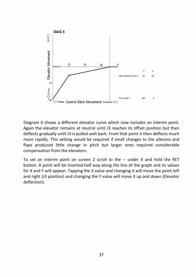
37
Diagram 6 shows a different elevator curve which now includes an interim point. Again the elevator remains at neutral until J3 reaches its offset position but then deflects gradually until J3 is pulled well back. From that point it then deflects much more rapidly. This setting would be required if small changes to the ailerons and flaps produced little change in pitch but larger ones required considerable compensation from the elevators.
To set an interim point on screen 2 scroll to the -- under X and hold the RET button. A point will be inserted half way along the line of the graph and its values for X and Y will appear. Tapping the X value and changing it will move the point left and right (J3 position) and changing the Y value will move it up and down (Elevator deflection).

38
Normally the end point value for Y will be -100 (or +100 if elevators go the other way). It is possible to edit this value as shown in Diagram 7. In this case the elevators deflect to their full extent when J3 is three quarters of the way back but then their deflection reduces as the stick is pulled further. Whether such an arrangement is necessary depends on how the model’s pitch responds to the flap and aileron settings but the radio makes provision for it if required.
Note that the values entered when setting the graph determine the pattern of movement of the elevators. They do not affect the volume of movement which is entered next to ELE on screen 2.
When Butterfly is used with flight conditions settings only apply to the Condition selected when they are entered.
TRIM MIX Malcolm Holt
This mix, which is only available in glider mode, allows aileron, flap and elevator positions to be offset to suit different flight conditions. For example the flaps and ailerons could be raised slightly to give a reflex section with a little down elevator to increase speed. Unlike Butterfly and camber mix there is no proportional movement. The settings are either on or off.
Enter the required control surface deflections on screen 1. Activate the mix on Screen 2. Different trim settings are probably best employed as elements of
39
different flight Conditions but an on/off switch may be assigned if required. (Settings only apply to the Condition selected when they are entered).
To prevent sudden changes of trim when a condition is switched on a condition delay may be set (see explanation under Conditions above). Additionally the speed of movement of the ailerons, flaps and elevators may be set independently. This is particularly useful when the mix is not switched on as an element in a Condition. A further cut switch may be set which will cancel the condition delay!
Setting an auto switch allows the trim mix to be deployed (as long as it is active) by another switch. For example it could be turned on by the switch which lowers the undercarriage wheel. Because the Trim Mix can be de-activated by its own switch or a Condition switch it is still possible to lower the undercarriage for an aero-tow take-off without deploying the trim mix.
AIRBRAKE Malcolm Holt
This mix, which is only available in Airplane mode, allows aileron, flap and elevator positions to be offset to increase drag for landing or diving manoeuvres. It is almost identical to Trim Mix in Glider Mode but, of course, does not have access to Condition switching and delay. The required control deflections are entered at screen 1.
The mix is activated on screen 2 and a switch can be assigned. There is no proportional movement. The settings are either on or off.
The Auto-SW setting allows the mix to be deployed by another switch/lever/dial as long as it is active. For example, the mix could be set to deploy when the throttle stick (J3) reaches a certain position.
To avoid abrupt changes of trim when the mix is switched on and off the control surfaces can be set to respond gradually by means of the speed settings on screen 2.
V-TAIL Malcolm Holt
This allows the travel of the rudder and elevator components to be adjusted on V-tail models.
AILEVATOR Malcolm Holt
This mix is only available when Tail is set to Ailevator in the Model Type menu. Where each elevator half is operated by a different servo this mix allows them to work together in response to the elevator stick (J2) and in opposite directions in response to the aileron stick (J1). This can improve roll rate.
40
The mix cannot be switched on and off in flight. Any combination of aileron and elevator movement may be set. With the default aileron movement set to zero the ailevator can simply be used as a convenient way of setting up a model with twin elevator servos on different channels. If a spare channel is available this is preferable to using a Y-lead. It provides an added degree of safety and allows the individual elevators to be trimmed separately with the sub-trim.
WINGLET Malcolm Holt
This mix is only available when Wing is set to Flying Wing and Tail is set to Winglet in the Model Type menu. It allows winglet rudders (if used) to be adjusted.
MOTOR
This function provides a very easy way of setting a safety switch when using an electric motor. It has the advantage that an alarm will sound if the motor is ‘live’ when the transmitter is turned on. With model type set to Glider, Motor is assigned by default to channel 3. To use the function with model type set to Airplane it is necessary to assign Motor in the Function Menu.
Activate the Motor Function and allocate the safety switch of your choice. Now set the motor control stick or switch (shown in the Function Menu) to its OFF position. Scroll to +0 next to Motor Off and hold RTN for a second. This stores the off position to which the speed controller will be set whenever the safety switch is on.
Screen 2/2 of the Motor Function allows the motor to power up and down gradually when being controlled by an on/off switch as is likely to be the case with an electric glider. To use this feature change Speed INH to ON.
The two IN speeds at the bottom of the screen determine the rates at which the motor decelerates to half speed and then again until it stops. Setting the maximum value of 27 will cause the motor to slow down very gradually. Leaving it at 0 will cause it to stop immediately. Setting a low value for the 1 position and then a higher value for the 2 position will cause the motor to slow down very quickly when it is first switched off and then more gradually. Changing the Speed 1>2 value in the bottom left of the screen allows you to alter the point at which the rates of deceleration change. This is indicated by the diagram at the right of the screen.
The two OUT speeds work in identical fashion but govern the way in which the motor accelerates when it is switched on.
Finally, by changing One Time from INH to ON, the motor can be set to power up and down gradually as described above when it is first operated. If it is switched on again during the same flight it will power up and down without any delay. The delay function is most easily reset by turning the transmitter off and on again.

41
The Speed element of the Motor Function has no relevance when using a proportional throttle stick rather than a switch. Given the absence of a servo slow function in Airplane Mode, this leaves its delay feature free to be used in a mix to provide a means of slowing the deployment of flaps, gear etc. For a worked example see my Futaba 8FG(S) Servo Slow notes.
RUDDER TO ELEVATOR MIX Malcolm Holt
This allows the elevators to move as slaves in response to the rudder stick. It could be used to help maintain direction in knife edge flight. When held in a knife-edge, some aircraft tend to pull in the direction of the undercarriage or the cockpit as they effectively “lift” sideways. The RUD/ELE mix can counteract this by applying a very small amount of up or down elevator when large amounts of rudder are applied. In this instance you would want the SLAVE elevators to move in the same direction whether the MASTER rudder is moved either right or left.
This mix is only available in AIRPLANE mode. It can be activated and a switch assigned if required. The elevators will respond directly to movements of the Rudder Stick (J4). If LINK is activated the elevators will also respond to any movement of the rudder which may be generated by other mixes (see PROG MIX for a more detailed explanation of LINK).
Up or down values for elevator deflection can be set by changing the +0 values at the top and bottom of the screen. In the example given above both values should be positive or both negative depending on whether up or down elevator is required. A 5-point curve can be set if required. This allows the mix to operate at large rudder deflections only. To activate the intermediate points scroll the cursor to one of the -- marks and hold RET. Values will now appear which can be edited in the usual way. Do the same for the other -- mark. For details of how to set a 5-point mix curve see PROG MIX. In this case rudder is the master (horizontal) and elevator the slave (vertical).
The mix can be activated and a switch assigned if required. The elevators will respond directly to movements of the Rudder Stick (J4). If LINK is activated the elevators will also respond to any movement of the rudder which may be generated by other mixes (see PROG MIX for a more detailed explanation of LINK).
SNAP ROLL Malcolm Holt
This sets the ailerons, rudder and elevator to perform positive and negative snap rolls to the left and right at the touch of a switch. (I rather thought that the point of radio control was to allow the pilot to control the aircraft).
On screen 1 you can set the amount of travel to be applied to each control surface. By default these are all set at 100% with correct positive and negative values. If
42
your servo installation gives a reversed movement then change the + or – sign for that control surface for all four roll directions. Snap roll will override any rate switch settings.
On screen 2 Master mode is set by default. In this setting the direction of the snap roll is first selected by a switch/dial/lever (see below) but the manoeuvre itself is always performed by operating the same master switch. This has the big advantage that the momentary switch SH can be used and the controls will return to neutral immediately it is released. If the mode is changed to Single it is not necessary to pre-select the direction of the roll. Operating the assigned switch both selects the direction and activates the servo movements. For example switch SA forward and back could be assigned to Left positive and negative rolls and switch SD similarly to right hand rolls. While this may appear more convenient, the need to locate and actively switch off the snap roll rather than just release a momentary switch appears fraught with danger.
If master mode is selected then it is necessary to assign a master switch, SH being the obvious choice. You may also assign a safety switch to disable the master and so prevent accidental operation. This can be any other switch/dial/lever or you could arrange to disable the snap roll whenever flaps or undercarriage are lowered.
On screen 3 switches can be assigned for each direction of roll. A possible arrangement could be to use the left and right sliders (LS and RS) forward for positive rolls and back for negative ones. Clearly it would be possible for two different directions of roll to be selected at the same time. Where this happens priority will be given to the roll nearest the top of the list on screen 3. For example, when a positive snap to the right is selected by its slider that is the manoeuvre which will be performed regardless of the position of other switches.
VIRTUAL CHANNELS Malcolm Holt
On screen 3 of the FUNCTION menu are four VIRTUAL channels (except when Frequency is set to MLT2).
As we have seen, the radio offers 7, 8 or 12 main channels depending on which frequency is used and each transmits signals to its own servo (or other electronic device such as an ESC). Each channel can be assigned to its own control so J2 moves the elevators; SE lowers the landing gear etc.
The radio also provides a huge array of mixes in which the control stick/lever/dial/switch of one function (the master) can simultaneously operate the servo of its own channel and those of others (its slaves). There is still only the

43
same number of servos working but they can be made to move in a huge variety of ways depending on how channels are combined.
A channel does not have to be connected to a servo of its own in order to work as the MASTER in a mix. When not set to MLT2 the radio provides 8 channels which can directly control their own servos but there are four extra ones which do not transmit data but which are still recognised by the software. These are the Virtual Channels V1 to V4 and they can be used as MASTER channels to operate the servos on any of the eight “real” channels.
When model type GLIDER is selected the radio assigns BUTTERFLY to Virtual channel V2 controlled by stick J3. Butterfly controls the ailerons, flaps and elevators in combination. It is a virtual channel because it does not have any servos of its own. It simply controls those on other channels while they are still able to be operated by their own assigned controls at the same time.
The following example illustrates how a virtual channel might be used and provides further examples of the use of the FUNCTION and PROG MIX menus. The programming is complex but, if you work through it steadily and check the PROG MIX notes, it serves as a good illustration of how PROG MIX works. It sets up a model with twin rudders which operate together from the usual rudder stick (J4). It also enables the two rudders to move in opposite directions so that they open outwards to act as airbrakes. This Virtual function is controlled by the left slider (LS).
Set up the model as AIRPLANE with 2-Aileron wing and re-set all model data.
In FUNCTION menu note that J4 is assigned to Rudder. On screen 2 go to Channel 7. It should be allocated to AUX 6 but change it to this if necessary. Now assign Control J4 and Trim T4. On the model we would plug the second rudder servo into channel 7. Now go to the servo monitor and move the rudder stick (J4) to check that both servos (4 and 7) are working together. Move the rudder trim and again check that it is adjusting both servos to allow in-flight trimming. If the rudders were fractionally out of alignment with each other you could adjust each one independently with its own sub-trim.
The model is now set up for twin rudders working together. To be able to operate them with a different control and in a different manner we can set up a virtual channel. Go to screen 3 of the FUNCTION menu. Virtual channel V2 should be free and allocated to AUX 1 but change it to this if necessary. Now assign Control LS (Left Slider) to the V2 channel. Do not assign a trim. Function AUX 1 is not connected to any servo but is still recognised by the software as a channel with its own control (LS). Accordingly we can now use it in any mix just like any other channel.

44
Go to PROG MIX and select mix 1. On screen 2/2 change INHibited to ACTive. Change MASTER AILeron to AUX 1 and SLAVE ELEvator to RUDder. The virtual AUX 1 function which exists only in the mind of the software is now set to drive the rudder which is a very real function with its own servo plugged into channel 4. First, though, we have to set the travel for the slave (rudder) servo.
Return to screen 1/2. Change the +0 nearest the top of the screen to -100. Push the Left Slider (LS) fully forward and then go to the servo monitor. Pull LS backwards. Once it reaches its mid-point you will see the rudder servo (Channel 4) start to move.
To be able to use the full movement of the Left Slider we need to set an offset. Return to PROG MIX – AUX1/RUD MIX and on screen 1/2 change the X OFFSET to +90. Set the Left Slider (LS) fully forward and look at the servo monitor again. This time the servo will begin to move when LS is pulled back 10% of its travel giving you much more control over the servo movement. To maximise the use of LS you could set the offset to 100% but you would have to be careful to push it fully forward in order to turn the rudder brakes off. Using 90% offset allows a margin of error.
We now need to set the second rudder to move in the opposite direction. Go to PROG MIX and select mix 2. On screen 2/2 change INHibited to ACTive. Change MASTER AILeron to AUX 1 (the Virtual channel) and SLAVE ELEvator to AUX 6 (the second rudder channel). On screen 1/2 change the +0 nearest the top of the screen to +100 and set the X OFFSET to +90. A final check of the servo monitor will show both rudders (channels 4 and 7) move in the same direction when the rudder stick (J4) is moved and in opposite directions (outward to act as brakes) when LS is moved. Note that J4 still gives rudder control when the brakes are deployed.
If you have really been paying attention you will have realised that we could have set up these mixes without using the virtual channel. We could have simply chosen H/W (Hardware) as the MASTER in each case and assigned LS as the control. However, by setting the rudder brakes up as a function (AUX 1) on a Virtual channel they become recognisable by the software just like any other function. This means that they can interact with all the other functions in the usual way. To illustrate the point let us set up one last mix. To keep things simple we will use the GEAR (channel 5) as the master to deploy the rudder brakes as it is already set up.
In PROG mix select mix 3. On screen 2/2 change INHibited to ACTive. Change MASTER AILeron to GEAR (channel 5 controlled by switch SE) and SLAVE ELEvator to AUX 1 (the Virtual rudder brake channel).
Change SLAVE AUX 1 LINK from OFF to + so that the two rudder mixes already linked to AUX 1 will become active.

45
Return to screen 1/2 and change the two +0 values at the top of the screen to +100% in order to get the rudders to move to the full extent of their travel. Change the Y OFFSET to -100 so that the rudder brake is closed when the SE GEAR switch is off.
Now go to PROG MIX 1 (AUX1/RUD) and on screen 2/2 change the MASTER AUX 1 link to + so that AUX1 responds to the input of the GEAR/AUX 1 mix. Similarly go to PROG MIX 2 (AUX1/AUX6) and change the MASTER AUX 1 link to +.
A check of the servo monitor will show that the rudder channels 4 and 7 now deploy as a brake when the gear is lowered with switch SE.
Malcolm Holt September 2011