fuses for semiconductor protection... g r l rectifier protection full range protection line / cable...
TRANSCRIPT
www.siba.de
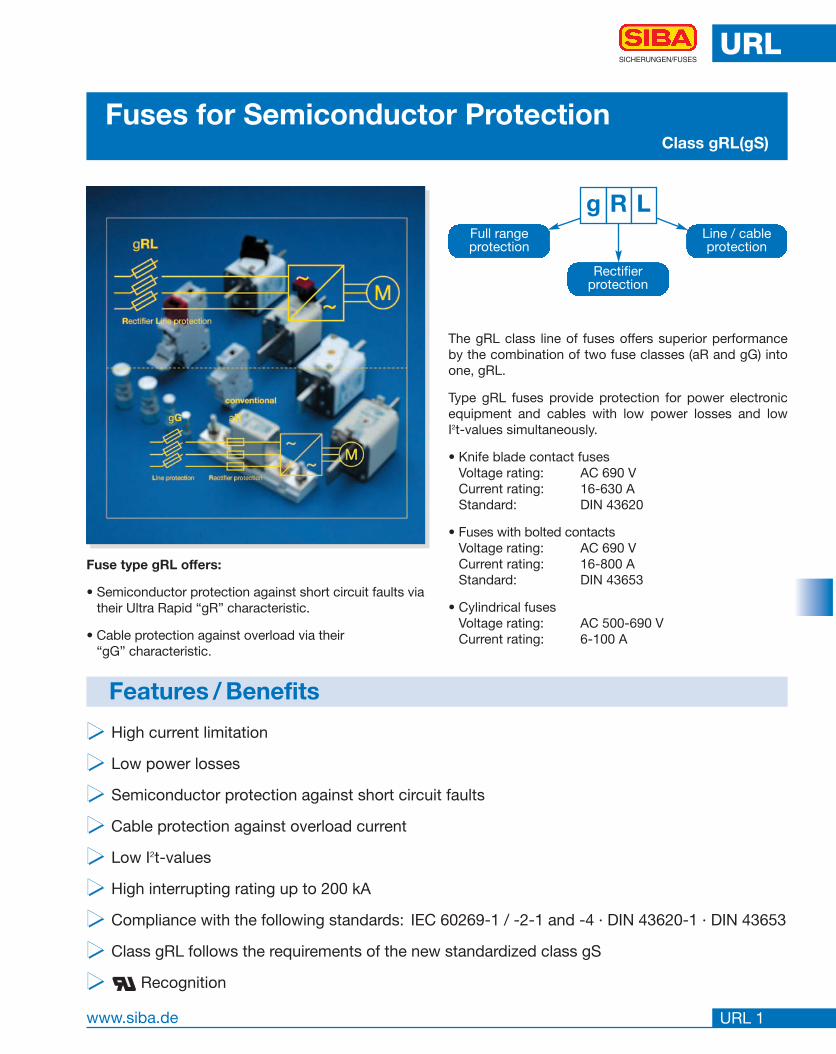
g R L
Rectifierprotection
Full rangeprotection
Line / cableprotection
URL
URL 1
SICHERUNGEN/FUSES
Fuses for Semiconductor ProtectionClass gRL(gS)
���� High current limitation
���� Low power losses
���� Semiconductor protection against short circuit faults
���� Cable protection against overload current
���� Low I2t-values
���� High interrupting rating up to 200 kA
���� Compliance with the following standards: IEC 60269-1 / -2-1 and -4 · DIN 43620-1 · DIN 43653
���� Class gRL follows the requirements of the new standardized class gS
���� Recognition
Features / Benefits
The gRL class line of fuses offers superior performanceby the combination of two fuse classes (aR and gG) intoone, gRL.
Type gRL fuses provide protection for power electronicequipment and cables with low power losses and lowI2t-values simultaneously.
• Knife blade contact fusesVoltage rating: AC 690 VCurrent rating: 16-630 AStandard: DIN 43620
• Fuses with bolted contactsVoltage rating: AC 690 VCurrent rating: 16-800 AStandard: DIN 43653
• Cylindrical fusesVoltage rating: AC 500-690 VCurrent rating: 6-100 A
Fuse type gRL offers:
• Semiconductor protection against short circuit faults viatheir Ultra Rapid “gR” characteristic.
• Cable protection against overload via their “gG” characteristic.

URL
URL 2
SICHERUNGEN/FUSES
Selection Guide
Rated Voltage [V] Size Part No. Techn. Data [Page]690 00 21 001 01 URL 42690 00 21 001 10 URL 42690 1 21 003 01 URL 43690 2 21 004 01 URL 43690 3 21 005 01 URL 43
Selection Guide Fuse-Base for Fuses with Knife Contacts
Fuses for Semiconductor ProtectionType gRL(gS)
Selection Guide Fuse-Base for Fuses with Screwcontacts
Rated Voltage [V] Fixing Center [mm] Rated Current [A] Part No. Techn. Data [Page]900 80 630 21 313 01 URL 35
1400 110 630 21 323 01 URL 35900 80 1250 21 313 02 URL 36
1400 110 1250 21 323 02 URL 361000 80 400 21 189 01 URL 371000 80 400 21 189 08 URL 37 with covers
Size Rated Voltage Contact Indicator Part No. Selector Guide Techn. Data[V] Type Type [Page] [Page]
D01 400 10 027 34 URL 4 URL 25D02 400 10 028 34 URL 4 URL 25D03 400 10 029 34 URL 4 URL 25DII 500 10 005 34 URL 5 URL 26DIII 500 10 007 34 URL 5 URL 26NH 000 690 knife contacts combi indicator 20 477 34 URL 6 URL 27NH 00 690 knife contacts combi indicator 20 209 34 URL 7 URL 27NH 1 690 knife contacts combi indicator 20 211 34 URL 8 URL 28NH 2 690 knife contacts combi indicator 20 212 34 URL 9 URL 29NH 3 690 knife contacts combi indicator 20 213 34 URL 10 URL 30NH 000 690 DIN 80 top indicator 20 282 34 URL 11 URL 27NH 000 690 DIN 80 with micro switch fitting 20 558 34 URL 13 URL 27NH 00 690 DIN 80 top indicator 20 189 34 URL 12 URL 27NH 00 690 DIN 80 with micro switch fitting 20 412 34 URL 14 URL 27SQB1 690 M 8 with micro switch fitting 20 252 34 URL 15 URL 28SQB2 690 M 10 with micro switch fitting 20 253 34 URL 16 URL 29SQB3 690 M 12 with micro switch fitting 20 254 34 URL 17 URL 30SQB1 690 DIN 110 with micro switch fitting 20 271 34 URL 18 URL 28SQB2 690 DIN 110 with micro switch fitting 20 274 34 URL 19 URL 29SQB3 690 DIN 110 with micro switch fitting 20 277 34 URL 20 URL 306.3 x 32 400 70 065 84 URL 21 URL 3110 x 38 600 cyl. contact caps 60 034 34 URL 22 URL 3210 x 38 600 PCB mounting 60 064 34 URL 22 URL 3214 x 51 690 cyl. contact caps 50 124 34 URL 23 URL 3314 x 51 690 cyl. contact caps with striker 50 126 34 URL 23 URL 3314 x 51 690 cyl. contact caps 50 129 34 URL 23 URL 3322 x 58 690 cyl. contact caps 50 140 34 URL 24 URL 3422 x 58 690 cyl. contact caps with striker 50 142 34 URL 24 URL 34
www.siba.de
Selection Guide Micro Switch
Type Rated Voltage Part No. Selector Guide[V] [Page]
GL-switch 250 28 002 01 URL 40GL-switch 250 28 002 02 URL 40B-switch 250 28 003 10 URL 41B-switch 250 28 003 11 URL 41B-switch 250 28 003 12 URL 41B-switch 250 28 003 20 URL 41B-switch 250 28 003 21 URL 41B-switch 250 28 003 22 URL 41B-switch 250 28 004 10 URL 41B-switch 250 28 004 11 URL 41B-switch 250 28 004 12 URL 41B-switch 250 28 004 20 URL 41B-switch 250 28 004 21 URL 41B-switch 250 28 004 22 URL 41
URL
URL 3
SICHERUNGEN/FUSES
Selection Guide Fuse-Clips
Size Part. No. Page Type Size Part. No. Page Type10 mm 61 017 01.2 38 14 mm 58 058 06 39 PCB14 mm 61 001 01.2 38 screw 22 mm 58 060 06 39 mountable22 mm 61 002 01.3 38 mountable27 mm 61 004 01.3 38
Selection Guide ZS-Modules for Fuses with Cylindrical Contact Caps
Size Indicator Part No. Techn. DataType [Page]
10 x 38 1 pole 51 063 04 URL 4410 x 38 2 pole 51 063 04.2 URL 4410 x 38 3 pole 51 063 04.3 URL 44 10 x 38 1 pole LED indicator 51 063 04.L URL 4410 x 38 2 pole LED indicator 51 063 04.2L URL 4410 x 38 3 pole LED indicator 51 063 04.3L URL 4414 x 51 1 pole 51 058 04 URL 4414 x 51 2 pole 51 058 04.2 URL 4414 x 51 3 pole 51 058 04.3 URL 4414 x 51 1 pole microswitch 51 058 04.S URL 4414 x 51 3 pole microswitch 51 058 04.3S URL 4422 x 58 1 pole 51 060 04 URL 4422 x 58 2 pole 51 060 04.2 URL 4422 x 58 3 pole 51 060 04.3 URL 4422 x 58 1 pole microswitch 51 060 04.S URL 4422 x 58 3 pole microswitch 51 060 04.3S URL 44
Fuses for Semiconductor ProtectionType gRL(gS)
www.siba.de

www.siba.de
URL
URL 4
SICHERUNGEN/FUSES
Rated Current Part No. Weight Pack[A] [kg/1]
6 10 027 34.6 0.006 5010 10 027 34.10 0.006 5013 10 027 34.13 0.006 5016 10 027 34.16 0.006 50
Size Rated Voltage Standard
D01 AC 400 V IEC 60269-4 / VDE 0636 part 40
UL R
ec.
Fuses for Semiconductor ProtectionType gRL(gS)
D 0.90 ” (22.5 mm)L 1.70 ” (43 mm)
Rated Current Part No. Weight Pack[A] [kg/1]
20 10 028 34.20 0.014 5025 10 028 34.25 0.014 5035 10 028 34.35 0.014 5050 10 028 34.50 0.014 5063 10 028 34.63 0.014 50
Size Rated Voltage Standard
D02 AC 400 V IEC 60269-4 / VDE 0636 part 40
UL R
ec.
Rated Current Part No. Weight Pack[A] [kg/1]
80 10 029 34.20 0.042 10100 10 029 34.25 0.042 10
Size Rated Voltage Standard
D03 AC 400 V IEC 60269-4 / VDE 0636 part 40
UL R
ec.
D 0.43 ” (11 mm)L 1.42 ” (36 mm)
D 0.60 ” (15,3 mm)L 1.42 ” (36 mm)

www.siba.de
URL
URL 5
SICHERUNGEN/FUSES
Rated Current Part No. Weight Pack[A] [kg/1]
6 10 005 34.6 0.031 2510 10 005 34.10 0.031 2513 10 005 34.13 0.031 2516 10 005 34.16 0.031 2520 10 005 34.20 0.031 2525 10 005 34.25 0.031 25
Size Rated Voltage Standard
DII AC 500 V IEC 60269-4 / VDE 0636 part 40
UL R
ec.
Fuses for Semiconductor ProtectionType gRL(gS)
D 0.87 ” (22 mm)L 1.97 ” (50 mm)
D 1.06 ” (27 mm)L 1.97 ” (50 mm)
Rated Current Part No. Weight Pack[A] [kg/1]
35 10 007 34.35 0.053 2550 10 007 34.50 0.053 2563 10 007 34.63 0.053 25
Size Rated Voltage Standard
DIII AC 500 V IEC 60269-4 / VDE 0636 part 40
UL R
ec.

URL
URL 6
SICHERUNGEN/FUSES
www.siba.de
Rated Current Part No. Weight Pack[A] [kg/1]
16 20 477 34.16 ✓ 0.11 320 20 477 34.20 ✓ 0.11 325 20 477 34.25 ✓ 0.11 332 20 477 34.32 ✓ 0.11 340 20 477 34.40 ✓ 0.11 350 20 477 34.50 ✓ 0.11 380 20 477 34.80 ✓ 0.11 3
Size Rated Voltage Standard
000 AC 690/700 V IEC 60269-4 / UL 248-13 / DIN 43620/1
UL R
ec.
Amax 2.13 ” (54 mm)B 0.60 ” (15 mm)C 1.85 ” (47 mm)D 0.80 ” (20.5 mm)E 1.60 ” (40.5 mm)F 0.24 ” (6 mm)G 1.38 ” (35 mm)H 2.05 ” (52 mm)I 0.28 ” (7 mm)L 3.07 ” (78 mm)
Fuses for Semiconductor ProtectionType gRL(gS)

URL
URL 7
SICHERUNGEN/FUSES
www.siba.de
Rated Current Part No. Weight Pack[A] [kg/1]
100 20 209 34.100 ✓ 0.154 3125 20 209 34.125 ✓ 0.154 3160 20 209 34.160 ✓ 0.154 3200 20 209 34.200 ✓ 0.154 3
Size Rated Voltage Standard
00 AC 690/700 V IEC 60269-4 / UL 248-13 / DIN 43620/1
UL R
ec.
Amax 2.13 ” (54 mm)B 0.59 ” (15 mm)C 1.85 ” (47 mm)D 1.16 ” (29.5 mm)E 1.80 ” (46 mm)F 0.24 ” (6 mm)G 1.38 ” (35 mm)H 2.28 ” (58 mm)I 0.50 ” (13 mm)L 3.07 ” (78 mm)
Fuses for Semiconductor ProtectionType gRL(gS)

URL
URL 8
SICHERUNGEN/FUSES
www.siba.de
Rated Current Part No. Weight Pack[A] [kg/1]
63 20 211 34.63 ✓ 0.37 380 20 211 34.80 ✓ 0.37 3
100 20 211 34.100 ✓ 0.37 3125 20 211 34.125 ✓ 0.37 3160 20 211 34.160 ✓ 0.37 3200 20 211 34.200 ✓ 0.37 3250 20 211 34.250 ✓ 0.37 3315 20 211 34.315 ✓ 0.37 3
Size Rated Voltage Standard
1 AC 690/700 V IEC 60269-4 / UL 248-13 / DIN 43620/1
UL R
ec.
Amax 2.95 ” (75 mm)B 0.80 ” (20 mm)C 2.56 ” (65 mm)D 1.65 ” (42 mm)E 2.03 ” (51.5 mm)F 0.24 ” (6 mm)G 1.57 ” (40 mm)H 2.52 ” (64 mm)I 0.55 ” (14 mm)L 5.30 ” (135 mm)
Fuses for Semiconductor ProtectionType gRL(gS)
URL
URL 9
SICHERUNGEN/FUSES
www.siba.de
Rated Current Part No. Weight Pack[A] [kg/1]
160 20 212 34.160 ✓ 0.37 3200 20 212 34.200 ✓ 0.37 3250 20 212 34.250 ✓ 0.37 3315 20 212 34.315 ✓ 0.65 3400 20 212 34.400 ✓ 0.65 3450 20 212 34.450 ✓ 0.65 3500 20 212 34.500 ✓ 0.65 3
Size Rated Voltage Standard
2 AC 690/700 V IEC 60269-4 / UL 248-13 / DIN 43620/1
UL R
ec.
Amax 2.95 ” (75 mm)B 1.02 ” (26 mm)C 2.56 ” (65 mm)D 2.10 ” (53 mm)E 2.32 ” (59 mm)F 0.24 ” (6 mm)G 1.90 ” (48 mm)H 2.83 ” (72 mm)I 0.55 ” (14 mm)L 5.90 ” (150 mm)
20 212 34≥ 315 A
Amax 2.95 ” (75 mm)B 0.80 ” (20 mm)C 2.56 ” (65 mm)D 1.65 ” (42 mm)E 2.03 ” (51.5 mm)F 0.24 ” (6 mm)G 1.90 ” (48 mm)H 2.83 ” (72 mm)I 0.55 ” (14 mm)L 5.90 ” (150 mm)
20 212 34≤ 250 A
Fuses for Semiconductor ProtectionType gRL(gS)
URL
URL 10
SICHERUNGEN/FUSES
www.siba.de
Rated Current Part No. Weight Pack[A] [kg/1]
315 20 213 34.315 0.65 3400 20 213 34.400 0.88 3500 20 213 34.500 0.88 3630 20 213 34.630 0.88 3
Size Rated Voltage Standard
3 AC 690/700 V IEC 60269-4 / UL 248-13 / DIN 43620/1
UL R
ec.
Amax 2.95 ” (75 mm)B 1.26 ” (32 mm)C 2.56 ” (65 mm)D 2.56 ” (65 mm)E 2.90 ” (73.5 mm)F 0.24 ” (6 mm)G 2.36 ” (60 mm)H 3.40 ” (86 mm)I 0.67 ” (17 mm)L 5.90 ” (150 mm)
20 213 34≥ 400 A
Amax 2.95 ” (75 mm)B 1.02 ” (26 mm)C 2.56 ” (65 mm)D 2.10 ” (53 mm)E 2.32 ” (59 mm)F 0.24 ” (6 mm)G 2.36 ” (60 mm)H 3.27 ” (83 mm)I 0.55 ” (14 mm)L 5.90 ” (150 mm)
20 213 34≤ 315 A
Fuses for Semiconductor ProtectionType gRL(gS)

URL
URL 11
SICHERUNGEN/FUSES
www.siba.de
Rated Current Part No. Weight Pack[A] [kg/1]
16 20 282 34.16 ✓ 0.17 620 20 282 34.20 ✓ 0.17 625 20 282 34.25 ✓ 0.17 632 20 282 34.32 ✓ 0.17 640 20 282 34.40 ✓ 0.17 650 20 282 34.50 ✓ 0.17 663 20 282 34.63 ✓ 0.17 680 20 282 34.80 ✓ 0.17 6
Size Rated Voltage Standard
000 AC 690 V IEC 60269-4 / UL 248-13 / DIN 43653
UL R
ec.
A 2.17 ” (55 mm)B 0.80 ” (20 mm)C 0.33 ” (8.5 mm)D 0.80 ” (20.4 mm)E 3.07 ” (78 mm)F 0.08 ” (2 mm)I 1.54 ” (39 mm)L(max) 3.94 ” (100 mm)
Fuses for Semiconductor ProtectionType gRL(gS)

URL
URL 12
SICHERUNGEN/FUSES
www.siba.de
Rated Current Part No. Weight Pack[A] [kg/1]
100 20 189 34.100 ✓ 0.19 3125 20 189 34.125 ✓ 0.19 3160 20 189 34.160 ✓ 0.19 3200 20 189 34.200 ✓ 0.19 3
Size Rated Voltage Standard
00 AC 690 / 700 V IEC 60269-4 / UL 248-13 / DIN 43653
UL R
ec.
A 2.17 ” (55 mm)B 1.13 ” (28,8 mm)C 0.40 ” (10,3 mm)D 1.16 ” (29,5 mm)E 3.07 ” (78 mm)F 0.10 ” (2,5 mm)I 1.85 ” (47 mm)L(max) 4.13 ” (105 mm)
Fuses for Semiconductor ProtectionType gRL(gS)

A 2.17 ” (55 mm)B 0.80 ” (20 mm)C 0.33 ” (8,5 mm)D 0.80 ” (20,4 mm)E 3.07 ” (78 mm)F 0.08 ” (2 mm)G 2.10 ” (53 mm)H 3.30 ” (83 mm)I 1.54 ” (39 mm)L(max) 3.94 ” (100 mm)
URL
URL 13
SICHERUNGEN/FUSES
www.siba.de
Rated Current Part No. Weight Pack[A] [kg/1]
16 20 558 34.16 ✓ 0.18 620 20 558 34.20 ✓ 0.18 625 20 558 34.25 ✓ 0.18 632 20 558 34.32 ✓ 0.18 640 20 558 34.40 ✓ 0.18 650 20 558 34.50 ✓ 0.18 663 20 558 34.63 ✓ 0.18 680 20 558 34.80 ✓ 0.18 6
Size Rated Voltage Standard
000 AC 690 / 700 V IEC 60269-4 / UL 248-13 / DIN 43653
UL R
ec.
Fuses for Semiconductor ProtectionType gRL(gS)

URL
URL 14
SICHERUNGEN/FUSES
www.siba.de
Rated Current Part No. Weight Pack[A] [kg/1]
100 20 412 34.100 ✓ 0.21 3125 20 412 34.125 ✓ 0.21 3160 20 412 34.160 ✓ 0.21 3200 20 412 34.200 ✓ 0.21 3
Size Rated Voltage Standard
00 AC 690 / 700 V IEC 60269-4 / UL 248-13 / DIN 43653
UL R
ec.
A 2.17 ” (55 mm)B 1.13 ” (28.8 mm)C 0.40 ” (10.3 mm)D 1.16 ” (29.5 mm)E 3.07 ” (78 mm)F 0.10 ” (2.5 mm)G 2.48 ” (63 mm)H 3.70 ” (93 mm)I 1.85 ” (47 mm)L(max) 4.13 ” (105 mm)
Fuses for Semiconductor ProtectionType gRL(gS)

URL
URL 15
SICHERUNGEN/FUSES
www.siba.de
Rated Current Part No. Weight Pack[A] [kg/1]
63 20 252 34.63 0.24 380 20 252 34.80 0.27 3
100 20 252 34.100 0.27 3125 20 252 34.125 0.27 3160 20 252 34.160 0.27 3200 20 252 34.200 0.27 3250 20 252 34.250 0.37 3315 20 252 34.315 0.37 3
Size Rated Voltage Standard
SQB1 AC 690 V IEC 60269-4 Metric Thread M 8
UL R
ec.
Fuses for Semiconductor ProtectionType gRL(gS)
A 1.87 ” (47.5 mm)B 0.94 ” (24 mm)D 2.00 ” (51 mm)G 2.60 ” (66 mm)H 3.50 ” (89 mm)L 2.00 ” (51 mm)M M8

URL
URL 16
SICHERUNGEN/FUSES
www.siba.de
Rated Current Part No. Weight Pack[A] [kg/1]
160 20 253 34.160 0.65 3200 20 253 34.200 0.65 3250 20 253 34.250 0.65 3315 20 253 34.315 0.65 3400 20 253 34.400 0.65 3450 20 253 34.450 0.65 3500 20 253 34.500 0.65 3
Size Rated Voltage Standard
SQB2 AC 690 V IEC 60269-4 Metric Thread M 10
UL R
ec.
Fuses for Semiconductor ProtectionType gRL(gS)
A 1.87 ” (47.5 mm)B 0.94 ” (24 mm)D 2.36 ” (60 mm)G 2.95 ” (75 mm)H 3.86 ” (98 mm)L 2.00 ” (51 mm)M M10

URL
URL 17
SICHERUNGEN/FUSES
www.siba.de
Rated Current Part No. Weight Pack[A] [kg/1]
315 20 254 34.315 0.88 3400 20 254 34.400 0.88 3500 20 254 34.500 0.88 3630 20 254 34.630 0.88 3710 20 254 34.710 0.88 3800 20 254 34.800 0.88 3
Size Rated Voltage Standard
SQB3 AC 690 V IEC 60269-4 Metric Thread M 12
UL R
ec.
Fuses for Semiconductor ProtectionType gRL(gS)
A 1.93 ” (49 mm)B 1.10 ” (28 mm)D 2.87 ” (73 mm)G 3.46 ” (88 mm)H 4.37 ” (111 mm)L 2.00 ” (51 mm)M M12

URL
URL 18
SICHERUNGEN/FUSES
www.siba.de
Rated Current Part No. Weight Pack[A] [kg/1]
63 20 271 34.63 0.24 380 20 271 34.80 0.27 3
100 20 271 34.100 0.27 3125 20 271 34.125 0.27 3160 20 271 34.160 0.27 3200 20 271 34.200 0.37 3250 20 271 34.250 0.37 3315 20 271 34.315 0.37 3
Size Rated Voltage Standard
SQB1 AC 690 V IEC 60269-4 DIN 43653
UL R
ec.
Fuses for Semiconductor ProtectionType gRL(gS)
A 1.87 ” (47.5 mm)B 1.02 ” (26 mm)C 0.43 ” (11 mm)D 2.00 ” (51 mm)E 4.17 ” (106 mm)F 0.24 ” (6 mm)G 2.60 ” (66 mm)H 3.50 ” (89 mm)L 5.28 ” (134 mm)

URL
URL 19
SICHERUNGEN/FUSES
www.siba.de
Rated Current Part No. Weight Pack[A] [kg/1]
160 20 274 34.160 0.65 3200 20 274 34.200 0.65 3250 20 274 34.250 0.65 3315 20 274 34.315 0.65 3400 20 274 34.400 0.65 3450 20 274 34.450 0.65 3500 20 274 34.500 0.65 3
Size Rated Voltage Standard
SQB2 AC 690 V IEC 60269-4 DIN 43653
UL R
ec.
Fuses for Semiconductor ProtectionType gRL(gS)
A 1.87 ” (47.5 mm)B 1.02 ” (26 mm)C 0.43 ” (11 mm)D 2.36 ” (60 mm)E 4.17 ” (106 mm)F 0.24 ” (6 mm)G 2.95 ” (75 mm)H 3.86 ” (98 mm)L 5.28 ” (134 mm)

URL
URL 20
SICHERUNGEN/FUSES
www.siba.de
Rated Current Part No. Weight Pack[A] [kg/1]
315 20 277 34.315 0.88 3400 20 277 34.400 0.88 3500 20 277 34.500 0.88 3630 20 277 34.630 0.88 3710 20 277 34.710 0.88 3800 20 277 34.800 0.88 3
Size Rated Voltage Standard
SQB3 AC 690 V IEC 60269-4 DIN 43653
UL R
ec.
Fuses for Semiconductor ProtectionType gRL(gS)
A 1.93 ” (49 mm)B 1.38 ” (35 mm)C 0.43 ” (11 mm)D 2.87 ” (73 mm)E 4.17 ” (106 mm)F 0.24 ” (6 mm)G 3.46 ” (88 mm)H 4.37 ” (111 mm)L 5.28 ” (134 mm)

www.siba.de
URL
URL 21
SICHERUNGEN/FUSES
Rated Current Part No. Weight Pack[A] [kg/1]
6.3 70 065 84.6.3 ✓ 0.009 108 70 065 84.8 ✓ 0.009 10
10 70 065 84.10 ✓ 0.009 1012.5 70 065 84.12.5 ✓ 0.009 1016 70 065 84.16 ✓ 0.009 1020 70 065 84.20 ✓ 0.009 10
Size Rated Voltage Standard
6.3 x 32 mm AC 400 V IEC 60269-4 VDE 0636 part 40
UL R
ec.
Fuses for Semiconductor ProtectionType gRL(gS)
A 1.26” (32 mm)B 0.25” (6.35 mm)

URL
URL 22
SICHERUNGEN/FUSES
www.siba.de
Rated Current Part No. Part No. Weight PackPCB Mounting
[A] [kg/1]
6 60 034 34.6 60 064 34.6 ✓ 0.9 108 60 034 34.8 60 064 34.8 ✓ 0.9 10
10 60 034 34.10 60 064 34.10 ✓ 0.9 1012 60 034 34.12 60 064 34.12 ✓ 0.9 1016 60 034 34.16 60 064 34.16 ✓ 0.9 1020 60 034 34.20 60 064 34.20 ✓ 0.9 1025 60 034 34.25 60 064 34.25 ✓ 0.9 1030 60 034 34.30 60 064 34.30 ✓ 0.9 10
Size Rated Voltage Standard
10 x 38 mm AC 500 V (IEC) · AC 600 V (UL) IEC 60269-4 / UL 248-13
UL R
ec.
Fuses for Semiconductor ProtectionType gRL(gS)
A 1.50 ” (38 mm)B 0.40 ” (10 mm)
PCB MountingA 1.50 ” (38 mm)B 0.40 ” (10 mm)C 0.03 ” (0.8 mm)D 1.53 ” (16.4 mm)E 0.65 ” (16.4 mm)F 0.20 ” (5.1 mm)G 0.05 ” (1.2 mm)

URL
URL 23
SICHERUNGEN/FUSES
www.siba.de
Rated Current Part No. Part No. Part No. Weight Packwithout Striker with Striker Fixing Center 63,5 mm
[A] [kg/1]
10 50 124 34.10 50 126 34.10 50 129 34.10 ✓ 0.022 1012 50 124 34.12 50 126 34.12 50 129 34.12 ✓ 0.022 1016 50 124 34.16 50 126 34.16 50 129 34.16 ✓ 0.022 1020 50 124 34.20 50 126 34.20 50 129 34.20 ✓ 0.022 1025 50 124 34.25 50 126 34.25 50 129 34.25 ✓ 0.022 1030 50 124 34.30 50 126 34.30 50 129 34.30 ✓ 0.022 1032 50 124 34.32 50 126 34.32 50 129 34.32 ✓ 0.022 1035 50 124 34.35 50 126 34.35 50 129 34.35 ✓ 0.022 1040 50 124 34.40 50 126 34.40 50 129 34.40 ✓ 0.022 10
Size Rated Voltage Standard
14 x 51 mm AC 690 / 700 V IEC 60269-4 / UL 248-13
UL R
ec.
Without StrikerA 2.00 ” (51 mm)B 0.55 ” (14 mm)
With StrikerA 2.00 ” (51 mm)B 0.55 ” (14 mm)Cmin 0.28 ” (7 mm)D 0.20 ” (4.9 mm)
Fixing Center 63,5 mmA 2.00 ” (51 mm)B 0.55 ” (14 mm)C 0.00 ” (63.5 mm)D 0.00 ” (77 mm)E 0.00 ” (8.7 mm)F 0.00 ” (5.5 mm)
Part No. 50 124 34. ... Part No. 50 129 34. ...
Part No. 50 126 34. ...
Fuses for Semiconductor ProtectionType gRL(gS)

URL
URL 24
SICHERUNGEN/FUSES
www.siba.de
UL R
ec.Rated Current Part No. Part No. Weight Pack
without Striker with Striker[A] [kg/1]
25 50 140 34.25 50 142 34.25 0.055 1030 50 140 34,30 50 142 34.30 0.055 1032 50 140 34.32 50 142 34.32 0.055 1035 50 140 34.35 50 142 34.35 0.055 1050 50 140 34.50 50 142 34.50 0.055 1063 50 140 34.63 50 142 34.63 0.055 1080 50 140 34.80 50 142 34.80 0.055 10
100 50 140 34.100 50 142 34.100 0.055 10
Size Rated Voltage Standard
22 x 58 mm AC 690 / 700 V IEC 60269-4 / UL 248-13
Fuses for Semiconductor ProtectionType gRL(gS)
Without Striker A 2.28 ” (58 mm)B 0.87 ” (22 mm)
With Striker A 2.28 ” (58 mm)B 0.87 ” (22 mm)Cmin 0.28 ” (7 mm)D 0.20 ” (4.9 mm)

URL
URL 25
SICHERUNGEN/FUSES
www.siba.de
Size Rated Voltage Operating Class Rated Breaking Capacity
D01/D02/D03 AC 400 V gRL(gS) 120 kA
Rated Part No. Power Pre-arcing Total l2t-valueCurrent Loss l2t-value @ 400 V
[A] [W] [A2s] [A2s]
6 10 027 34.6 0.7 3.0 6010 10 027 34.10 1.3 7.4 15013 10 027 34.13 1.7 12.0 24016 10 027 34.16 1.9 30.0 60020 10 028 34.20 1.7 46.0 70025 10 028 34.25 2.1 104.0 1 60035 10 028 34.35 2.9 330.0 5 00050 10 028 34.50 3.9 740.0 11 00063 10 028 34.63 5.1 1 310.0 19 70080 10 029 34.80 5.5 2 500.0 37 500
100 10 029 34.100 6.5 4 600.0 79 000
Cut-Off Characteristics Time-Current Characteristics
Virt
ual P
re-a
rcin
g Ti
me
Cut
-off
Cur
rent
Pea
k
RMS Prospective Current
Prospective Short Circuit Current
t(s)Ic(kA)
I(A)
I(kA)
Electrical Characteristics

www.siba.de
URL
URL 26
SICHERUNGEN/FUSES
Electrical Characteristics
Size Rated Voltage Operating Class Rated Breaking Capacity
DII/DIII AC 500 V gRL(gS) 120 kA
Rated Part No. Power Pre-arcing Total l2t-value Current Loss l2t-value @ 500 V
[A] [W] [A2s] [A2s]
6 10 005 34.6 0.8 3.0 6010 10 005 34.10 1.6 7.4 15013 10 005 34.13 2.4 13.0 26016 10 005 34.16 2.4 30.0 60020 10 005 34.20 2.9 52.0 1 04025 10 005 34.25 2.9 120.0 2 40035 10 007 34.35 4.0 330.0 3 30050 10 007 34.50 6.0 740.0 7 40063 10 007 34.63 7.0 1 300.0 13 000
Cut-Off Characteristics Time-Current CharacteristicsV
irtua
l Pre
-arc
ing
Tim
e
Cut
-off
Cur
rent
Pea
k
RMS Prospective Current
Prospective Short Circuit Current
t(s)Ic(kA)
I(A)
I(kA)

www.siba.de
URL
URL 27
SICHERUNGEN/FUSES
Rated Part No. Part No. Part No. Power Pre-arcing Total l2t-valueCurrent Knife Contacts Screw Contacts Screw Contacts Loss l2t-value @ 690 V
Fitting for GL-Switch Fitting for GL-Switch without Fitting[A] [W] [A2s] [A2s]
16 20 477 34.16 20 558 34.16 20 282 34.16 3.2 18 18020 20 477 34.20 20 558 34.20 20 282 34.20 3.6 41 41025 20 477 34.25 20 558 34.25 20 282 34.25 4.2 74 74035 20 477 34.35 20 558 34.35 20 282 34.35 5.2 170 1 70040 20 477 34.40 20 558 34.40 20 282 34.40 5.6 300 3 00050 20 477 34.50 20 558 34.50 20 282 34.50 6.5 460 4 60063 20 477 34.63 20 558 34.63 20 282 34.63 7.6 840 8 40080 20 477 34.80 20 558 34.80 20 282 34.80 8.8 1 800 18 000
100 20 209 34.100 20 412 34.100 20 189 34.100 10.5 3 000 30 000125 20 209 34.125 20 412 34.125 20 189 34.125 12.0 6 000 60 000160 20 209 34.160 20 412 34.160 20 189 34.160 17.0 1 400 80 000200 20 209 34.200 20 412 34.200 20 189 34.200 21.0 16 000 110 000
Size Rated Voltage Operating Class Rated Breaking Capacity
000/00 AC 690 / 700 V gRL(gS) 200 kA
Electrical Characteristics
Cut-Off Characteristics Time-Current Characteristics
Virt
ual P
re-a
rcin
g Ti
me
Cut
-off
Cur
rent
Pea
k
RMS Prospective Current
Prospective Short Circuit Current
t(s)Ic(kA)
I(A)
I(kA)
Arc voltage-Diagram
UL____
(VAC) KB KW
UB____
(VAC)
UB____
(VAC)
IB___
(IN)
Reduction factor for total I2t-value Reduction factor for power loss

www.siba.de
URL
URL 28
SICHERUNGEN/FUSES
Electrical Characteristics
Rated Part No. Part No. Part No. Power Pre-arcing Total l2t-value Current Knife Contacts Screw Contacts Screw contacts Loss l2t-value @ 690 V
Metric Thread M8 Fitting for B-SwitchFitting for B-Switch
[A] [W] [A2s] [A2s]
63 20 211 34.63 20 252 34.63 20 271 34.63 8.0 840 5,30080 20 211 34.80 20 252 34.80 20 271 34.80 9.5 1 800 11 300
100 20 211 34.100 20 252 34.100 20 271 34.100 12.0 3 000 19 000125 20 211 34.125 20 252 34.125 20 271 34.125 12.6 6 000 38 000160 20 211 34.160 20 252 34.160 20 271 34.160 23.0 7 400 47 000200 20 211 34.200 20 252 34.200 20 271 34.200 27.0 15 000 95 000250 20 211 34.250 20 252 34.250 20 271 34.250 33.0 30 000 190 000315 20 211 34.315 20 252 34.315 20 271 34.315 44.0 43 000 271 000
Size Rated Voltage Operating Class Rated Breaking Capacity
SQB1 AC 690 / 700 V gRL(gS) 200 kA
Time-Current CharacteristicsV
irtua
l Pre
-arc
ing
Tim
e
RMS Prospective Current
t(s)
I(A)
Cut-Off Characteristics
Cut
-off
Cur
rent
Pea
k
Prospective Short Circuit Current
Ic(kA)
I(kA)
Arc voltage-Diagram
UL____
(VAC) KB KW
UB____
(VAC)
UB____
(VAC)
IB___
(IN)
Reduction factor for total I2t-value Reduction factor for power loss

www.siba.de
URL
URL 29
SICHERUNGEN/FUSES
Electrical Characteristics
Rated Part No. Part No. Part No. Power Pre-arcing Total l2t-value Current Knife Contacts Screw Contacts Screw contacts Loss l2t-value @ 690 V
Metric Thread M10 Fitting for B-SwitchFitting for B-Switch
[A] [W] [A2s] [A2s]
160 20 212 34.160 20 253 34.160 20 274 34.160 23 7 400 47 000200 20 212 34.200 20 253 34.200 20 274 34.200 27 15 000 95 000250 20 212 34.250 20 253 34.250 20 274 34.250 30 30 000 190 000315 20 212 34.315 20 253 34.315 20 274 34.315 40 43 000 271 000350 20 212 34.350 20 253 34.350 20 274 34.350 43 58 000 310 000400 20 212 34.400 20 253 34.400 20 274 34.400 48 85 000 442 000450 20 212 34.450 20 253 34.450 20 274 34.450 50 107 000 560 000500 20 212 34.500 20 253 34.500 20 274 34.500 63 170 000 880 000
Size Rated Voltage Operating Class Rated Breaking Capacity
SQB2 AC 690 / 700 V gR (gS) 200 kA
Time-Current Characteristics
Virt
ual P
re-a
rcin
g Ti
me
RMS Prospective Current
t(s)
I(A)
Cut-Off Characteristics
Cut
-off
Cur
rent
Pea
k
Prospective Short Circuit Current
Ic(kA)
I(kA)
Arc voltage-Diagram
UL____
(VAC) KB KW
UB____
(VAC)
UB____
(VAC)
IB___
(IN)
Reduction factor for total I2t-value Reduction factor for power loss

www.siba.de
URL
URL 30
SICHERUNGEN/FUSES
Electrical Characteristics
Rated Part No. Part No. Part No. Power Pre-arcing Total l2t-value Current Knife Contacts Screw Contacts Screw contacts Loss l2t-value @ 690 V
Metric Thread M12 Fitting for B-SwitchFitting for B-Switch
[A] [W] [A2s] [A2s]
315 20 213 34.315 20 254 34.315 20 277 34315 38 43 000 271 000350 20 213 34.350 20 254 34.350 20 277 34.350 42 58 000 310 000400 20 213 34.400 20 254 34.400 20 277 34.400 46 85 000 442 000450 20 213 34.450 20 254 34.450 20 277 34.450 48 107 000 560 000500 20 213 34.500 20 254 34.500 20 277 34.500 55 170 000 880 000560 20 213 34.560 20 254 34.560 20 277 34.560 58 190 000 1 100 000630 20 213 34.630 20 254 34.630 20 277 34.630 64 280 000 1 400 000710 20 254 34.710 20 277 34.710 69 420 000 1 900 000800 20 254 34.800 20 277 34.800 74 620 000 2 500 000
Size Rated Voltage Operating Class Rated Breaking Capacity
SQB3 AC 690 / 700 V gRL(gS) 200 kA
Time-Current CharacteristicsV
irtua
l Pre
-arc
ing
Tim
e
RMS Prospective Current
t(s)
I(A)
Cut-Off Characteristics
Cut
-off
Cur
rent
Pea
k
Prospective Short Circuit Current
Ic(kA)
I(kA)
Arc voltage-Diagram
UL____
(VAC) KB KW
UB____
(VAC)
UB____
(VAC)
IB___
(IN)
Reduction factor for total I2t-value Reduction factor for power loss

www.siba.de
URL
URL 31
SICHERUNGEN/FUSES
Electrical Characteristics
Size Rated Voltage Operating Class Rated Breaking Capacity
6.3 x 32 mm AC 400 V gRL(gS) 120 kA
Rated Part No. Voltage Drop Power Pre-arcing Total l2t-value Current Loss l2t-value @ 500 V
[A] [mV] [W] [A2s] [A2s]
6.3 70 065 84.6.3 190 1.2 1.8 118 70 065 84.8 190 1.5 3.0 18
10 70 065 84.10 180 1.8 5.1 3112.5 70 065 84.12.5 150 1.9 12.0 6916 70 065 84.16 150 2.3 20.0 12020 70 065 84 160 3.2 35.0 210
Time-Current Characteristics
Virt
ual P
re-a
rcin
g Ti
me
RMS Prospective Current
t(s)
I(A)
Cut-Off Characteristics
Cut
-off
Cur
rent
Pea
k
Prospective Short Circuit Current
Ic(kA)
I(kA)
KW
IB___
(IN)
Reduction factor for power loss

www.siba.de
URL
URL 32
SICHERUNGEN/FUSES
Electrical Characteristics
Size Rated Voltage Operating Class Rated Breaking Capacity
10 x 38 mm AC 600 V gRL(gS) 200 kA
Rated Part No. Part No. Power Pre-arcing Total l2t-value Current PCB Mounting Loss l2t-value @ 500 V
[A] [W] [A2s] [A2s]
6 60 034 34.6 60 064 34.6 1.0 2.5 208 60 034 34.8 60 064 34.8 1.3 3.3 36
10 60 034 34.10 60 064 34.10 1.6 5.1 4112 60 034 34.12 60 064 34.12 1.9 8.7 6916 60 034 34.16 60 064 34.16 2.4 17.0 13020 60 034 34.20 60 064 34.20 3.5 29.0 24025 60 034 34.25 60 064 34.25 3.8 66.0 53030 60 034 34.30 60 064 34.30 4.3 120.0 950
Cut-off Characteristics Time-Current CharacteristicsV
irtua
l Pre
-arc
ing
Tim
e
Cut
-off
Cur
rent
Pea
k
RMS Prospective Current
Prospective Short Circuit Current
t(s)Ic(kA)
I(A)
I(kA)
Arc voltage-Diagram
UL____
(VAC) KB KW
UB____
(VAC)
UB____
(VAC)
IB___
(IN)
Reduction factor for total I2t-value Reduction factor for power loss

www.siba.de
URL
URL 33
SICHERUNGEN/FUSES
Electrical Characteristics
Size Rated Voltage Operating Class Rated Breaking Capacity
14 x 51 mm AC 690 V gRL(gS) 200 kA
Rated Part No. Part No. Part No. Power Pre-arcing Total l2t-value Current without Striker with Striker Fixing Center Loss l2t-value @ 690 V
63,5 mm[A] [W] [A2s] [A2s]
10 50 124 34.10 50 126 34.10 50 129 34.10 1.9 8 6012 50 124 34.12 50 126 34.12 50 129 34.12 2.3 12 9016 50 124 34.16 50 126 34.16 50 129 34.16 2.8 25 19020 50 124 34.20 50 126 34.20 50 129 34.20 3.0 46 34025 50 124 34.25 50 126 34.25 50 129 34.15 3.2 100 74030 50 124 34.30 50 126 34.30 50 129 34.30 3.8 190 1 40032 50 124 34.32 50 126 34.32 50 129 34.32 4.0 250 1 90035 50 124 34.35 50 126 34.35 50 129 34.35 4.2 370 2 80040 50 124 34.40 50 126 34.40 50 129 34.40 4.4 420 3 100
Cut-Off Characteristics Time-Current Characteristics
Virt
ual P
re-a
rcin
g Ti
me
Cut
-off
Cur
rent
Pea
k
RMS Prospective Current
Prospective Short Circuit Current
104
103
s
10 2
10 1
10 0
10 -1
10-2
10 0
2
3
456
8
10 1 10 2 10 3 A2 3 4 5 6 8 2 3 4 5 6 8 2 3 4 5 6 8 2 3 4
10 A
16 A
20 A
25
A30 A
12 A
35 A
40
A
32
A
t(s)Ic(kA)
I(A)
I(kA)
Arc voltage-Diagram
UL____
(VAC) KB KW
UB____
(VAC)
UB____
(VAC)
IB___
(IN)
Reduction factor for total I2t-value Reduction factor for power loss

Cut-Off Characteristics Time-Current CharacteristicsV
irtua
l Pre
-arc
ing
Tim
e
Cut
-off
Cur
rent
Pea
k
RMS Prospective Current
Prospective Short Circuit Current
t(s)Ic(kA)
I(A)
I(kA)
Arc voltage-Diagram
UL____
(VAC) KB KW
UB____
(VAC)
UB____
(VAC)
IB___
(IN)
Reduction factor for total I2t-value Reduction factor for power loss
www.siba.de
URL
URL 34
SICHERUNGEN/FUSES
Size Rated Voltage Operating Class Rated Breaking Capacity
22 x 58 mm AC 700 V gRL(gS) 200 kA
Rated Part No. Part No. Power Pre-arcing Total l2t-value Current without Striker with Striker Loss l2t-value @ 690 V
[A] [W] [A2s] [A2s]
25 50 140 34.25 50 142 34.25 3.6 100 80030 50 140 34.30 50 142 34.30 4.6 190 1 50032 50 140 34.32 50 142 34.32 4.8 250 2 00035 50 140 34.35 50 142 34.35 5.0 370 3 00040 50 140 34.40 50 142 34.40 5.2 420 3 40050 50 140 34.50 50 142 34.50 5.4 870 7 00063 50 140 34.63 50 142 34.63 6.8 1 300 10 50080 50 140 34.80 50 142 34.80 7.5 2 500 20 000
100 50 140 34.100 50 142 34.100 7.7 4 600 37 000
Electrical Characteristics

www.siba.de
A 5.90 ” (150 mm)B 3.35 ” (85 mm)C 0.63 ” (16 mm)D 0.83 ” (21 mm)E 3.15 ” (80 mm)F 0.30 ” (8 mm)G 1.80 ” (46 mm)H(Size 1) 5.00 ” (127 mm)H(Size 2) 5.12 ” (130 mm)H(Size 3) 5.40 ” (137 mm)I 0.35 ” (9 mm)J(Size 1) 4.10 ” (104 mm)J(Size 2) 4.25 ” (108 mm)J(Size 3) 4.53 ” (115 mm)K 0.98 ” (25 mm)L(max) 8.07 ” (205 mm)M M 10N 2.36 ” (60 mm)O 1.57 ” (40 mm)
Fixing Center80 mm
URL
URL 35
SICHERUNGEN/FUSES
Fuse Base Size Rated Current Standard
for Fuses with Bolted Connections DIN Type SQB1, 2 and 3 630 A DIN 43653
Rated Voltage Part No. Fixing Center max. RatedNut Torque Power Acceptance
[V] [mm] [Nm] [W]
900 21 313 01 80 48 601 400 21 323 01 110 48 60
A 7.10 ” (180 mm)B 3.35 ” (85 mm)C 0.63 ” (16 mm)D 0.83 ” (21 mm)E 4.33 ” (110 mm)F 0.30 ” (8 mm)G 1.80 ” (46 mm)H(Size 1) 5.00 ” (127 mm)H(Size 2) 5.12 ” (130 mm)H(Size 3) 5.40 ” (137 mm)I 0.35 ” (9 mm)J(Size 1) 4.10 ” (104 mm)J(Size 2) 4.25 ” (108 mm)J(Size 3) 4.53 ” (115 mm)K 0.98 ” (25 mm)L(max) 8.07 ” (205 mm)M M 10N 2.36 ” (60 mm)O 1.57 ” (40 mm)
Fixing Center110 mm

www.siba.de
URL
URL 36
SICHERUNGEN/FUSES
Fuse Base Size Rated Current Standard
for Fuses with Bolted Connections DIN Type SQB1, 2 and 3 1250 A DIN 43653
Rated Voltage Part No. Fixing Center max. RatedNut Torque Power Acceptance
[V] [mm] [Nm] [W]
900 21 313 02 80 48 1101 400 21 323 02 110 48 110
A 5.90 ” (150 mm)B 3.35 ” (85 mm)C 0.63 ” (16 mm)D 0.83 ” (21 mm)E 3.15 ” (80 mm)F 0.30 ” (8 mm)G 1.81 ” (46 mm)H(Size 1) 5.00 ” (127 mm)H(Size 2) 5.12 ” (130 mm)H(Size 3) 5.40 ” (137 mm)I 0.35 ” (9 mm)J(Size 1) 4.10 ” (104 mm)J(Size 2) 4.25 ” (108 mm)J(Size 3) 4.53 ” (115 mm)K 0.98 ” (25 mm)L(max) 8.07 ” (205 mm)M M 10N 2.36 ” (60 mm)O 1.57 ” (40 mm)
Fixing Center80 mm
A 7.10 ” (180 mm)B 3.35 ” (85 mm)C 0.63 ” (16 mm)D 0.83 ” (21 mm)E 4.33 ” (110 mm)F 0.30 ” (8 mm)G 1.81 ” (46 mm)H(Size 1) 5.00 ” (127 mm)H(Size 2) 5.12 ” (130 mm)H(Size 3) 5.40 ” (137 mm)I 0.35 ” (9 mm)J(Size 1) 4.10 ” (104 mm)J(Size 2) 4.25 ” (108 mm)J(Size 3) 4.53 ” (115 mm)K 0.98 ” (25 mm)L(max) 8.07 ” (205 mm)M M 10N 2.36 ” (60 mm)O 1.57 ” (40 mm)
Fixing Center110 mm

www.siba.de
URL
URL 37
SICHERUNGEN/FUSES
A 4.96 ” (126 mm)B 1.57 ” (40 mm)C 0.50 ” (13 mm)D 0.75 ” (19 mm)E 3.15 ” (80 mm)F 0.12 ” (3 mm)G 1.73 ” (44 mm)H 4.40 ” (112 mm)I 0.26 ” (6,5 mm)J 0.60 ” (15,5 mm)K 0.63 ” (16 mm)L(max) 5.75 ” (146 mm)M M 8N 0.98 ” (25 mm)
Part No. 21 189 01Rated Current: 400 ARated Power Acceptance: 34 WNut Torque: 12 Nm
Size Rated Voltage Standard
Fuse-Base 400 A 000 and 00 AC 1000 V DIN 43653
1000 V
1000 VPart No. 21 189 08Rated Current: 400 ARated Power Acceptance: 34 WNut Torque: 12 Nm
with covers
Size Rated Voltage Standard
Fuse-Base 400 A 000 and 00 AC 1000 V DIN 43653

URL
URL 38
SICHERUNGEN/FUSES
www.siba.de
Fuse-Clip Screw Mountable
Clamping Plate
A 0.50 ” (13 mm)B 0.55 ” (14 mm)C 0.70 ” (18 mm)D 0.17 ” (4.2 mm)E 0.20 ” (5 mm)
Power Acceptance4 W61 017 01.2Size 10
A 0.63 ” (16 mm)B 0.63 ” (16 mm)C 0.90 ” (23 mm)D 0.17 ” (4.2 mm)E 0.26 ” (6.5 mm)
Power Acceptance6 W61 001 01.2Size 14
A 0.75 ” (19 mm)B 1.06 ” (27 mm)C 1.50 ” (38 mm)D 0.18 ” (4.5 mm)E 0.16 ” (4 mm)F 0.30 ” (8 mm)G 0.30 ” (8 mm)
Power Acceptance12 W61 002 01.3Size 22
A 1.06 ” (27 mm)B 2.30 ” (58.4 mm)C 4.55 ” (115.6 mm)
A 0.40 ” (10 mm)B 0.35 ” (9 mm)C 0.08 ” (2 mm)D 0.17 ” (4.2 mm)
Part No.63 017 01
A 0.73 ” (18.5 mm)B 0.60 ” (15 mm)C 0.12 ” (3 mm)D M4E 0.16 ” (4 mm)F 0.30 ” (8 mm)G 0.30 ” (8 mm)
Part No.63 002 01
Power Acceptance12 W61 004 01.3Size 27
To be used with fuse clips 61 017 01.2and 61 001 01.2
To be used with fuse clips 61 002 01.3

URL
URL 39
SICHERUNGEN/FUSES
www.siba.de
Fuse-Clip PCB Mountable
A 0.63 ” (16 mm)B 0.55 ” (14 mm)C 0.60 ” (15.5 mm)D 0.20 ” (5 mm)E 0.14 ” (3.5 mm)F 0.03 ” (0.75 mm)G 0.42 ” (10.7 mm)H 0.14 ” (3.5 mm)
Power Acceptance6 W58 058 06Size 14
Fuse-Clip PCB Mountable
A 0.67 ” (17 mm)B 0.87 ” (22 mm)C 0.90 ” (23 mm)D 0.24 ” (6 mm)E 0.14 ” (3.5 mm)F 0.03 ” (0.75 mm)G 0.42 ” (10.7 mm)H 0.14 ” (3.5 mm)
Power Acceptance12 W58 060 06Size 22

www.siba.de
URL
URL 40
SICHERUNGEN/FUSES
Rated Current
GL-Switch 5 A For Fuses with Topindicator and Fitting for Micro Switch
Dimensions
Part No. 28 002 01 (Black Hammer) Part No. 28 002 02 (Red Hammer)
Part No. Use for Weight Pack[kg]
28 002 01 SQB1-3 NH00 DIN 80 0.02 10(20 2xx xx) (20 412 xx)
28 002 02 NH000-4 NH000 DIN 80 0.02 10(DIN 43620) (20 558 xx)
Interrupting Rating
AC 250 V AC 250 V DC 33 V DC 26 V
ohmsch ind. ohmsch L/R 10 ms
5 A 3 A 3 A 3 A
Terminals
AMP 2,8 x 0,5 (IEC 760)

www.siba.de
URL
URL 41
SICHERUNGEN/FUSES
Rated Current
B-switch 10 A For Fuse-Links with Adapter for Micro Switch Fitting
Type Part No. Insulating Voltage Interupting Rating
min. Load Requirements AC / DC max. Data AC / DC
[V] [Vohmsch] [mA] [V] [A]
28 003 10 1 300 5 5028 003 20 250 12
standard 28 003 11 2 400 30 1028 003 2128 003 12 35 1028 003 22 5 000 100 5
Insulating Part No. Part No. Change-Over Weight PackVoltage up to Standard Low Level Circuits
[V] [g]
1 300 28 003 10 28 004 10 1 25 101 300 28 003 20 28 004 20 2 32 102 400 28 003 11 28 004 11 1 25 102 400 28 003 21 28 004 21 2 32 105 000 28 003 12 28 004 12 1 25 105 000 28 003 22 28 004 22 2 32 10
Type Part No. Insulating Voltage Interupting Rating
min. Load Requirements AC / DC max. Data
[V] [Vohmsch] [mA] [V] [A]
28 004 10 1 30028 004 20 do not use below AC 250 10
low level 28 004 11 2 40028 004 21 5 128 004 12 DC 35 128 004 22 5 000
Standard Low Level
Part No. Part No.28 003 10 / 20 28 004 10 / 20
Standard Low Level
Part No. Part No.28 003 11 / 21 28 004 11 / 21
Standard Low Level
Part No. Part No.28 003 12 / 22 28 004 12 / 22
up to 1,300 V up to 2,400 V up to 5,000 V
1 Change-over circuit2 contact terminals6.3 x 0.8 mm
2 Change-over circuit2x2 contact terminals6.3 x 0.8 mm

www.siba.de
URL
URL 42
SICHERUNGEN/FUSES
Fuse-Base Size Rated Voltage Standard
for Fuses with Knife Contacts 00 AC 500/690 V DIN 43620
A 3.94 ” (100 mm)B 0.80 ” (20 mm)C 1.26 ” (32 mm)D 3.90 ” (99 mm)E 1.32 ” (33.5 mm)F 1.14 ” (29 mm)G 2.32 ” (59 mm)H 3.40 ” (86 mm)I 2.24 ” (57 mm)J 4.72 ” (120 mm)L 5.30 ” (135 mm)M M 8N 0.98 ” (25 mm)O 0.30 ” (7.5 mm)
Part No.21 001 01
A 3.94 ” (100 mm)B 0.80 ” (20 mm)C 1.18 ” (30 mm)D 3.66 ” (93 mm)E 1.24 ” (31.5 mm)F 0.94 ” (24 mm)G 2.20 ” (56 mm)H 3.15 ” (80 mm)I 2.24 ” (57 mm)J 4.72 ” (120 mm)K 0.34 ” (8.7 mm)L 5.30 ” (135 mm)M M 8N 0.98 ” (25 mm)O 0.30 ” (7.5 mm)P 0.60 ” (15.5 mm)
Part No.21 001 10

www.siba.de
URL
URL 43
SICHERUNGEN/FUSES
A 7.87 ” (200 mm)B 1.30 ” (33 mm)C 1.97 ” (50 mm)D 7.32 ” (186 mm)E 2.68 ” (68 mm)F 1.38 ” (35 mm)G 3.58 ” (91 mm)H 4.72 ” (120 mm)I 3.15 ” (80 mm)J 5.83 ” (148 mm)L 9.06 ” (230 mm)M M 10N 1.18 ” (30 mm)O 0.40 ” (10 mm)P 0.65 ” (16.5 mm)V 0.40 ” (10 mm)
Size 2Power Acceptance 45 W
Part No. 21 004 01
Fuse-Base Size Rated Voltage Standard
for Fuses with Knife Contacts 1 - 3 AC 500/690 V DIN 43620
A 8.27 ” (210 mm)B 1.30 ” (33 mm)C 2.17 ” (55 mm)D 8.86 ” (225 mm)E 3.35 ” (85 mm)F 1.38 ” (35 mm)G 3.78 ” (96 mm)H 5.00 ” (127 mm)I 3.15 ” (80 mm)J 5.83 ” (148 mm)L 9.84 ” (250 mm)M M 10N 1.18 ” (30 mm)O 0.40 ” (10 mm)P 0.65 ” (16.5 mm)V 0.40 ” (10 mm)
Size 3Power Acceptance 60 W
Part No. 21 005 01
A 6.90 ” (175 mm)B 1.30 ” (33 mm)C 1.97 ” (50 mm)D 7.00 ” (178 mm)E 2.52 ” (64 mm)F 1.38 ” (35 mm)G 3.30 ” (84 mm)H 4.20 ” (107 mm)I 3.15 ” (80 mm)J 5.83 ” (148 mm)L 7.78 ” (200 mm)M M 10N 1.18 ” (30 mm)O 0.40 ” (10 mm)P 0.65 ” (16.5 mm)V 0.40 ” (10 mm)
Size 1Power Acceptance 32 W
Part No. 21 003 01

www.siba.de
URL
URL 44
SICHERUNGEN/FUSES
ZS-Module for Fuses with Cylindrical Contact Caps
H ED
CB
A
G
F
MN P
W
J
K
HG
FJ
R
T
BC
DE
A
J
S
W
K
Z
U
P
NM
X
JK
NM
HG
FJ
R
S
T
BC
DE
A
W
ZP
X
H 3.13 ” (79.5 mm)J 1.69 ” (43 mm)K 0.40 ” (10 mm)M 1.77 ” (45 mm)N 0.65 ” (16.5 mm)P 0.13 ” (3.2 mm)W 0.10 ” (2.5 mm)
A 3.07 ” (78 mm)B 0.70 ” (17.8 mm)C 1.40 ” (35.6 mm)D 2.10 ” (53.4 mm)E 2.80 ” (71.2 mm)F 2.20 ” (56 mm)G 2.40 ” (61 mm)
M 1.77 ” (45 mm)N 1.28 ” (32.5 mm)P 0.40 ” (10.5 mm)R 1.48 ” (37.5 mm)S 0.30 ” (8 mm)T 0.80 ” (20.5 mm)U � 0.33 ” (8.5 mm)W 0.1 ” (2.5 mm)X 3.17 ” (80.5 mm)Z � 0.17 ” (4.4 mm)
A 4.04 ” (102.5 mm)B 1.04 ” (26.5 mm)C 2.10 ” (53 mm)D 3.13 ” (79.5 mm)E 4.17 ” (106 mm)F 2.66 ” (67.5 mm)G 3.00 ” (76 mm)H 3.70 ” (94.2 mm)J 2.07 ” (52.5 mm)K 0.30 ” (8 mm)
Size 14 x 51Part No. 51 058 04 51 058 04.S 1 pol.
51 058 04.2 2 pol.51 058 04.3 51 058 04.3S 3 pol.
S= Micro switch
Power Acceptance: 6 W
M 1.77 ” (45 mm)N 2.00 ” (50.5 mm)P 0.30 ” (7.5 mm)R 1.57 ” (40 mm)S 0.30 ” (8 mm)T 1.06 ” (27 mm)W 0.10 ” (2.5 mm)X 4.30 ” (109.5 mm)Z � 0.17 ” (4.4 mm)
A 5.50 ” (140 mm)B 1.40 ” (35.6 mm)C 2.80 ” (71.2 mm)D 4.20 ” (106.8 mm)E 5.60 ” (142.4 mm)F 2.97 ” (75.5 mm)G 3.44 ” (87.5 mm)H 4.35 ” (110.5 mm)J 2.10 ” (53 mm)K 0.63 ” (16 mm)
Size 10 x 38Part No. 51 063 04.DC for 1000 V DC
51 063 04 51 063 04.L 1 pol.51 063 04.2 51 063 04.2L 2 pol.51 063 04.3 51 063 04.3L 3 pol.
L= Light Emitting Diode (LED) Indicator
Power Acceptance: 4 W
Size 22 x 58Part No. 51 060 04 51 060 04.S 1 pol.
51 060 04.2 2 pol.51 060 04.3 51 060 04.3S 3 pol.
S= Micro switch
Power Acceptance: 12 W