further development of an execution strategy analysis (esa ... · wm2017 conference, march 5-9,...
TRANSCRIPT

WM2017 Conference, March 5-9, 2017, Phoenix, Arizona, USA
1
Further Development of an Execution Strategy Analysis (ESA) Capability and Tool for the Management of Spent Nuclear Fuel (SNF) –
17146 Natalia Saraeva *, William Nutt *, Ralph Stoll **, John Greeves **, James Voss **, Ian Miller **, William Mozingo**, Alan Keizur ***,
Alyssa Neir *** * Argonne National Laboratory
** Predicus LLC *** Golder Associates Inc.
ABSTRACT1 An Execution Strategy Analysis (ESA) capability and tool are being developed to evaluate alternative execution strategies for the potential future deployment of a consolidated Interim Storage Facility as part of an integrated waste management system. Application of the ESA approach not only leverages but also goes beyond traditional project analysis tools. The ESA tool allows for ongoing performance assessment of the evolving project execution plans that take into account significant assumptions, risks, and uncertainties throughout the project lifecycle. Development and application of the ESA capability and tool continued in 2016, primarily focusing on enhancing its flexibility to model a range of scenarios regarding how an integrated system for managing spent nuclear fuel and high-level radioactive waste could be deployed.
INTRODUCTION
The U.S. Department of Energy’s (DOE’s) goal is to develop solutions for the long-term, sustainable management of the nation’s spent nuclear fuel (SNF) and high-level radioactive waste (HLW). The DOE Office of Nuclear Energy (DOE-NE), Office of Spent Fuel and Waste Disposition’s (SFWD) Integrated Waste Management (IWM) program is applying integrated waste management system analysis, system engineering, and decision analysis principles to inform future decisions regarding potential future nuclear waste management system architectures. Foundational capabilities and tools are being developed to support and inform the future deployment of a consolidated interim storage facility (ISF) and large-scale transportation of SNF.
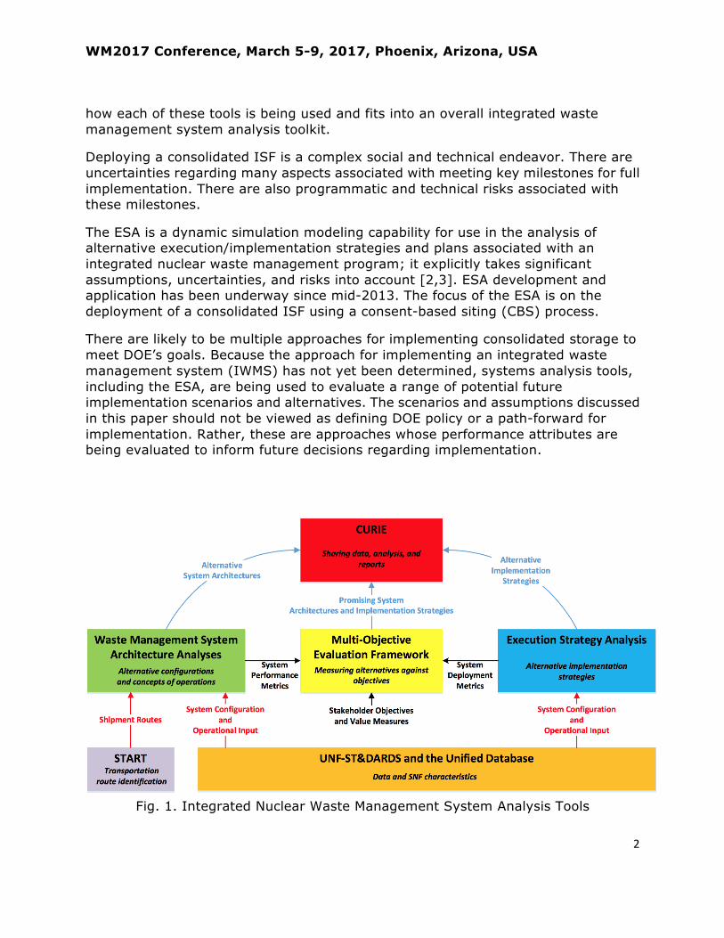
These tools include Used Nuclear Fuel Storage, Transportation, & Disposal Analysis Resource and Data System (UNF-ST&DARDS), Stakeholder Tool for Assessing Radioactive Transportation (START), Transportation and Storage Logistics (TSL), Next-Generation System Analysis Model (NGSAM), Execution Strategy Analysis (ESA), Multi-Objective Evaluation Framework (MOEF), and the Centralized Used Fuel Resource for Information Exchange (CURIE) [1]. Figure 1 provides the framework for
1 This technical paper reflects concepts which could support future decision-‐making by DOE. No inferences should be drawn from this paper regarding future actions by DOE. To the extent this technical paper conflicts with the provisions of the Standard Contract, the Standard Contract provisions prevail.
WM2017 Conference, March 5-9, 2017, Phoenix, Arizona, USA
2
how each of these tools is being used and fits into an overall integrated waste management system analysis toolkit.
Deploying a consolidated ISF is a complex social and technical endeavor. There are uncertainties regarding many aspects associated with meeting key milestones for full implementation. There are also programmatic and technical risks associated with these milestones.
The ESA is a dynamic simulation modeling capability for use in the analysis of alternative execution/implementation strategies and plans associated with an integrated nuclear waste management program; it explicitly takes significant assumptions, uncertainties, and risks into account [2,3]. ESA development and application has been underway since mid-2013. The focus of the ESA is on the deployment of a consolidated ISF using a consent-based siting (CBS) process.
There are likely to be multiple approaches for implementing consolidated storage to meet DOE’s goals. Because the approach for implementing an integrated waste management system (IWMS) has not yet been determined, systems analysis tools, including the ESA, are being used to evaluate a range of potential future implementation scenarios and alternatives. The scenarios and assumptions discussed in this paper should not be viewed as defining DOE policy or a path-forward for implementation. Rather, these are approaches whose performance attributes are being evaluated to inform future decisions regarding implementation.
Fig. 1. Integrated Nuclear Waste Management System Analysis Tools

WM2017 Conference, March 5-9, 2017, Phoenix, Arizona, USA
3
ESA APPROACH
The formal ESA approach goes beyond traditional project analysis tools. The ESA is a dynamic simulation tool that explicitly models and assesses the impacts of uncertainties (activity durations and costs), constraints (policy, legislation, regulatory), risks (technical, non-technical) and opportunities in the development of one or more consolidated ISFs for used fuel management.
The ESA development and analysis process is a top-down approach that begins with defining the ultimate objective of a task or project and developing the integrated logic of an implementation strategy. The goal is to dynamically couple all of the activities that need to be performed and to provide coherent information and the ability to weigh options at a strategic level. The end result is a dynamic, probabilistic simulation model that is well organized and is only as complex as necessary. The model provides for flexibility to re-structure or re-sequence activities and allows for the rapid evaluation of alternatives. A broad group of subject matter experts (SMEs) develops and peer-reviews activity logic and identifies and quantifies program risks, opportunities, and uncertainties; engaging a team of SMEs is critical to the success of the ESA approach. Figure 2 shows the iterative steps used in the development and application of the ESA.
Fig. 2. ESA Development Process
Mitigation Strategies
Analyze Results
Build Model
Risks
Data (Duration &
Cost)
Determine Milestones
& Activities
Definition of
Success

WM2017 Conference, March 5-9, 2017, Phoenix, Arizona, USA
4
Definition of Success: The first step in the ESA process is to determine what is trying to be achieved. In prior versions of the ESA [3,4] this was defined as the initial operations of a pilot ISF followed by the initial operations of a co-located, larger ISF. In 2016 a major enhancement was made to the ESA capability and tool to provide the ability to analyze scenarios for up to three interim storage sites that could be deployed in phases as part of an integrated waste management system. In addition, the model now allows for the pilot ISF and larger ISF to be sited in different locations.
Determine Milestones & Activities: These are determined through the development of a success precedence diagram (SPD), a graphical tool that describes the basic sequence of high-level milestones necessary to meet the defined objective. The process begins with the desired outcome and then holistically details the various precedence requirements and their pathways that lead to the desired outcome. The SPD must identify all critical milestones, their linkages, and alternative approaches. The SPD development serves as a way to identify all of the logical precedence requirements for project success.
The next step is to identify activities associated with achieving each milestone. The activities are then mapped onto the SPD to provide the overall framework for the dynamic simulation model. Specific project activities are modeled at an appropriate level of detail in order to adequately represent program performance without adding unnecessary complexity.
Data: The key attributes of each activity are then determined, including duration, cost, and predecessor activities/milestones. The SMEs use design documents, implementation plans, and experience on similar types of projects, other information, and subjective judgments to define the activities and their attributes. Typically, many of the attributes have significant uncertainty, and in these cases the attribute is defined by a probability distribution rather than by a single value.
Risks: A broad spectrum of risks, both technical and non-technical, that could affect the implementation strategies are then identified and quantified through a facilitated discussion with SMEs. Risks are quantified in terms of their potential consequences, along with the likelihood of those consequences being realized. Potential consequences include impacts to activity durations, costs, and changes to implementation strategies. In this context, risk includes those events that could negatively impact an implementation strategy as well as risks that if realized could positively impact an implementation strategy. Both types of risks and their quantified attributes are catalogued in a risk registry.
Build Model: A dynamic, probabilistic simulation model is then developed based upon the milestone/activity logic, the attributes of each activity, and the quantified positive and negative risks.

WM2017 Conference, March 5-9, 2017, Phoenix, Arizona, USA
5
Analyze Results: The simulation model is used to evaluate the performance of various project scenarios and options; its results include uncertainty in the cost, schedule, and other defined metrics. The sensitivities of key outputs to the various input factors and of specific activities, milestones, and risks to the overall program critical path are evaluated also. This helps to determine potential benefits and priorities of reducing uncertainties that impact key project objectives.
Mitigation Strategies: Knowledge regarding which activities and milestones are likely to be on critical path and how uncertainties and risks affect their completion and the completion of the overall project allows for the identification of potential mitigation strategies that could be used. Such potential mitigation strategies are developed through facilitated discussion with SMEs following the ESA process steps discussed above.
The entire ESA approach is iterative. The development of the model and simulation results provide insight regarding the reconsideration of milestone and activity sequences and the identification of potential alternative strategies to improve implementation and reduce or mitigate risk.
There have been three main iterations of the ESA tool since 2013. The first iteration involved a limited number of SMEs leading to the development of a simulation model to demonstrate the utility of the ESA process and the insights that could be gained. The second iteration, utilizing a broader group of SMEs, including those within the commercial nuclear industry, enhanced the ESA tool through the identification of additional activities and milestones to improve implementation performance and the quantification of input factors; additional positive and negative risks based upon industry experience were identified also [2]. The third iteration enhanced the ESA model’s usefulness in several areas: risk mitigation strategies; capability to analyze constrained funding scenarios; developing and analyzing generic consent-based siting scenario alternatives; and developing dry canister storage design concepts for analysis in conjunction with siting scenario alternatives [3].
The ESA approach has produced a draft process and tool that provides a possible framework with key milestones that likely need to be achieved and the activities that should be completed to deploy a consolidated ISF. The process has also resulted in a risk registry associated with possible deployment strategies. Taken all together, the ESA approach helps provide a possible understanding of the overall effort (cost, schedule) required for siting a consolidated ISF as a part of an IWMS.
ACTIVITY STRUCTURE AND SEQUENCING
The fully integrated activity and milestone logic structure provides the foundation for developing the dynamic ESA simulation model. As discussed above, the specific activities are modeled at a high ‘strategic’ level, sufficient to adequately represent program performance without adding unnecessary complexity. Some of the major ESA component models are discussed in this section.

WM2017 Conference, March 5-9, 2017, Phoenix, Arizona, USA
6
Consent Based Siting
The ESA contains three models of different CBS approaches: abbreviated, medium, and extended [2]. All three CBS models assume that the public is engaged in the development of the CBS process. The major difference between the three CBS approaches assumed in the ESA model is in the duration and level of engagement during the phases of development of the CBS process and exploration of interest (community studies possibly funded through grants) in potential volunteer communities. In other words, the difference is in the number of steps and duration of pre-negotiation engagement (prior to negotiating a consent agreement) assumed for each general siting approach. The assumptions associated with the different CBS approaches are discussed below.
Extended - three rounds of community studies are available during the exploration of interest phase through site evaluation, beginning with small initial community studies and increasing in scope and depth with each round.
Medium - two rounds of exploratory community studies (first small, then larger in scope) conducted during the exploration of interest phase through to site evaluation.
Abbreviated - one round of community exploratory studies performed during the exploration of interest phase.
ESA Model of a Strategy for a Site-Specific Environmental Impact Statement for a Federal Facility
The National Environmental Protection Act (NEPA) (42 USC 4321 et seq.) requires federal agencies to consider and publicly disclose the environmental impacts of, and reasonable alternatives to, their proposed actions before making decisions. Proposed DOE actions associated with the consolidated interim storage of commercial SNF and related wastes, including associated transportation, could result in significant impacts, which may require the preparation of an Environmental Impact Statement (EIS) per NEPA, and the implementing regulations of the Council on Environmental Quality CEQ (40 CFR Parts 1500-1508) and DOE (10 CFR 1021).
The ESA model is being used to analyze different alternative approaches for meeting the NEPA requirements to help inform the determination of a future implementation strategy. Once that strategy is determined, then it will no longer be necessary to maintain alternatives within the ESA.
The ESA model currently assumes that a site-specific EIS is developed for all sites under consideration after a down-select step in a consent-based siting process and for a range of facility design alternatives that could be deployed at those sites. The overall activity/milestone logic currently implemented in the ESA model is shown in Figure 3. Specific steps assumed in the ESA model include:

WM2017 Conference, March 5-9, 2017, Phoenix, Arizona, USA
7
Fig. 3. Possible NEPA Approach Modeled in ESA
• Development and completion of an initial strategy for satisfying NEPA
requirements.
• Potential issuance of an Advanced Notice of Intent (ANOI) early in the consent-based siting process to inform the public and interested parties early about the first phase of the integrated waste management system, proposed transportation and storage action, and DOE’s possible intent to ultimately prepare an EIS for this activity. The ANOI could also inform these same parties that public comments and other information received through stakeholder and public interactions conducted for the consent-based siting process could be considered as early scoping for DOE’s preliminary identification of alternatives and environmental issues to be analyzed in the EIS.
• A notice of intent (NOI) for a site-specific EIS. It is assumed in the ESA that this is issued when potential sites are identified for further consideration in the consent-based siting process, ‘formally’ initiating the NEPA process for one or more interim storage facilities and the associated transportation infrastructure.
• NEPA scoping meetings to establish the scope for the EIS.
• Preparation and issuance of a draft EIS. It is assumed that its development requires the identification of a range of design alternatives, the identification of preliminary transportation routes between origin sites, and the determination of sites under consideration.
• Conduct of public hearings and receipt of comments from the public.
• Review of public comments and feedback to develop a final EIS (including a comment response document as required under NEPA).
• Issuance of a record of decision (ROD). It is assumed that issuance occurs upon completion of negotiations to identify one or more sites for hosting an interim storage facility.
Develop NOI for Site(s)-Specific NEPA
NEPA Scoping Meetings
Prepare/ Issue Draft Site(s)-Specific EIS
Conduct Public Hearings and Receipt of Public
Comments
Review Comments and Complete Final EIS Issue ROD
Potential Sites Identified
Preliminary Transportation
Routes Identified
Site Characterization
Range of Design
Alternatives Identified
Draft Negotiations / Relevant
Agreements
Complete Initial NEPA Strategy
Potential Development and Issuance of
Advance NOI
General Discussion with
Stakeholders and Public Complete
Begin “Active” Consent-Based
ISF Siting Process
NRC Licensing
DEIS
WM2017 Conference, March 5-9, 2017, Phoenix, Arizona, USA
8
ESA Modeling of Federal Facility Licensing
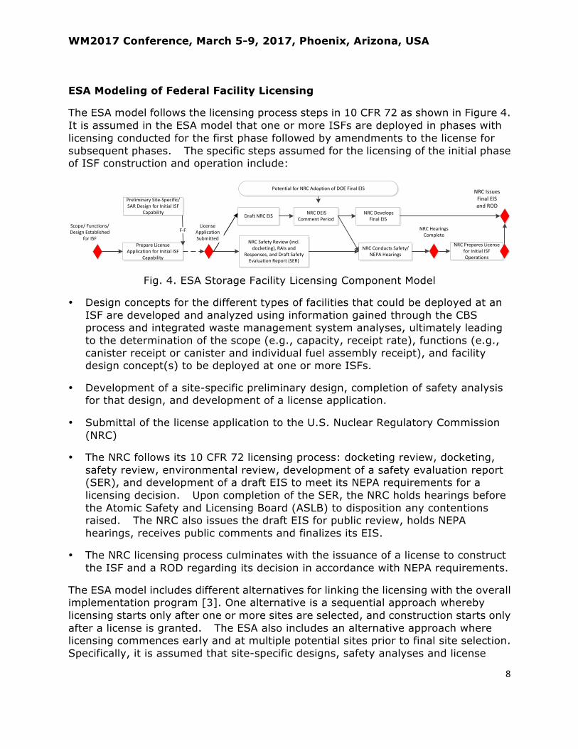
The ESA model follows the licensing process steps in 10 CFR 72 as shown in Figure 4. It is assumed in the ESA model that one or more ISFs are deployed in phases with licensing conducted for the first phase followed by amendments to the license for subsequent phases. The specific steps assumed for the licensing of the initial phase of ISF construction and operation include:
Fig. 4. ESA Storage Facility Licensing Component Model
• Design concepts for the different types of facilities that could be deployed at an ISF are developed and analyzed using information gained through the CBS process and integrated waste management system analyses, ultimately leading to the determination of the scope (e.g., capacity, receipt rate), functions (e.g., canister receipt or canister and individual fuel assembly receipt), and facility design concept(s) to be deployed at one or more ISFs.
• Development of a site-specific preliminary design, completion of safety analysis for that design, and development of a license application.
• Submittal of the license application to the U.S. Nuclear Regulatory Commission (NRC)
• The NRC follows its 10 CFR 72 licensing process: docketing review, docketing, safety review, environmental review, development of a safety evaluation report (SER), and development of a draft EIS to meet its NEPA requirements for a licensing decision. Upon completion of the SER, the NRC holds hearings before the Atomic Safety and Licensing Board (ASLB) to disposition any contentions raised. The NRC also issues the draft EIS for public review, holds NEPA hearings, receives public comments and finalizes its EIS.
• The NRC licensing process culminates with the issuance of a license to construct the ISF and a ROD regarding its decision in accordance with NEPA requirements.
The ESA model includes different alternatives for linking the licensing with the overall implementation program [3]. One alternative is a sequential approach whereby licensing starts only after one or more sites are selected, and construction starts only after a license is granted. The ESA also includes an alternative approach where licensing commences early and at multiple potential sites prior to final site selection. Specifically, it is assumed that site-specific designs, safety analyses and license
Prepare License
Application for Initial ISF
Capability
NRC Safety Review (incl.
docketing), RAIs and
Responses, and Draft Safety
Evaluation Report (SER)
NRC Conducts Safety/
NEPA Hearings
NRC Prepares License
for Initial ISF
Operations
F-F
Draft NRC EIS NRC DEIS
Comment Period
NRC Develops
Final EIS
NRC Issues
Final EIS
and ROD
EARLY LICENSINGBegin site-specific design,
safety analysis and license
application development on
multiple potential host sites
Sequential LicensingBegin site-specific design,
safety analysis, and license
application development after
site is selected
EARLY LICENSINGSubmit licenses for site(s)
selected EARLY CONSTRUCTIONWhen licensing hearings begin
seek authorization to begin
early site preparation and
initial construction in advance
of receipt of a license
SEQUENTIAL CONSTRUCTIONBegin early site preparation
and initial construction when
a license is received
Scope/ Functions/
Design Established
for ISF
License
Application
Submitted
Preliminary Site-Specific/
SAR Design for Initial ISF
Capability
NRC Hearings
Complete
Potential for NRC Adoption of DOE Final EIS

WM2017 Conference, March 5-9, 2017, Phoenix, Arizona, USA
9
applications are developed for facilities on multiple potential host sites and the license applications are submitted when the DOE draft EIS is complete.
The ESA also includes an alternative approach where construction of some items commences early with NRC authorization prior to receipt of a final license. Specifically, it is assumed that when the licensing hearings begin, authorization to begin early site preparation and initial construction, in advance of receipt of a license, is sought and granted.
ESA Modeling of Transportation Asset Acquisition
The ESA model includes steps to acquire the necessary assets to transport SNF from reactor sites to an ISF. This includes transportation casks having 10 CFR 71 certificates of compliance and cask and buffer cars that are certified to meet Association of American Railroads (AAR) standard S-2043. The specific steps assumed in the ESA model are shown in Figure 5 and include:
Fig. 5. ESA Transportation Asset Acquisition Component Model
• Design and fabrication of prototype cask and buffer railcars for testing to meet AAR standard S-2043 requirements. This effort is underway [4].
• Individual rail car followed by full-consist (locomotive, cask, buffer, and escort railcars) testing.
• Development of site-specific plans for de-inventorying each shutdown site. These plans are assumed to include a recommended de-inventory approach, transportation route analysis, concept of operations, safety and security plan/procedures, emergency response and preparedness, etc.
• Conducting integrated waste management system analysis of strategies and approaches for accepting SNF from shutdown reactor sites.
• Establishing a queue for accepting SNF from the shutdown reactor sites.
UNDER CONTRACT
Contracting, Design, Dynamic Modeling, & AAR Approval to Build Railcars for Testing
Fabricate Cask Car, Buffer Cars, and Other Equipment for Testing
Full Consist TestingIndividual Testing of Cask and Buffer Cars
Rolling Stock Procurement / Fabrication / Delivery for Initial ISF Operations
NEPA ROD
Prototype Railcars Ready for Full
Consist Testing
Establish Transportation Assets (Fleet Size and Casks)
for Initial Operations
ISF Site Selected and Approved
?
Rolling Stock Procurement
Strategy Developed
?
Establish Acceptance Queue for Shutdown Sites
Perform Shutdown Site Acceptance Analysis
Develop Site-Specific De-Inventory Plans
Obtain/ Revise/ Update/ Verify Certificate of Compliance for Casks,
Overpacks for Initial Transfer
Transportation Cask / Overpack Procurement/ Fabrication/ Delivery for
Initial Transfer
?
Cask Procurement Strategy Developed
?
Select Cask Type for Initial Transfer

WM2017 Conference, March 5-9, 2017, Phoenix, Arizona, USA
10
• Determination of transportation asset requirements (rolling stock fleet size and transportation casks) for the established acceptance queue.
• Development of rolling stock and transportation cask procurement strategies.
• Selection of the cask to be used for the initial transportation of SNF from a shutdown reactor site to the ISF.
• Verify, and if necessary obtain, revise, or update the certification of compliance for the transportation casks to be used for the initial transport of SNF from a shutdown reactor site.
• Acquisition of the necessary rolling stock (cask, buffer, and escort rail cars) and transportation casks. The ESA model assumes these acquisition actions do not begin until the NEPA ROD for DOE’s decision regarding the ISF is issued.
ESA Modeling of Transportation Route Readiness
The ESA model includes steps to establish transportation routes between the shutdown reactor sites and the ISF and for the training of emergency responders along the routes. The ESA model assumes that technical assistance and funds are provided to States and Tribes for training of public safety officials through whose jurisdictions SNF could be transported in accordance with Section 180(c) of the Nuclear Waste Policy Act (NWPA). The specific steps assumed in the ESA model are shown in Figure 6 and include:
Fig. 6. ESA Transportation Route Readiness Component Model
• Conceptualize initial transportation routing between shutdown reactor sites and potential ISF locations. This is assumed in the ESA model to begin when potential host site volunteers come forward in the consent-based siting process.
UNDERWAY
NWPA Section 180 (c) Planning
Complete Contracts with Railroads and Others for Shipments
Initial Transportation
Route Ready
Obtain NRC Route Approval/State Permits for First Route
NWPA Section 180(c) TrainingNWPA Section 180 (c)
Route Announcement/Grants
NWPA Section 180 (c) Process Development
Final Route Selection for
Initial Shipment
Complete Transportation Route Selection
Conceptualize Initial Transportation Routing
Near Site Route Planning to Rail Transfer Point
Potential Host Site Volunteers Come
Forward
“Shortlist” of Potential Sites
Identified ?
Establish Acceptance Queue for Shutdown Sites

WM2017 Conference, March 5-9, 2017, Phoenix, Arizona, USA
11
• Conduct near-site route planning to rail transfer points near shutdown reactor sites.
• Complete transportation route selection between the shutdown reactor sites and potential ISF site locations. It is assumed in the ESA model that this activity begins when a “shortlist” of potential ISF sites is identified through the consent-based siting process.
• Select the final set of routes for the initial shipment of SNF from the shutdown sites to one or more selected ISF sites.
• Fully develop the process for implementing the financial and technical NWPA Section 180(c) program. This effort has been initiated and an exercise to evaluate the efficacy of DOE’s revised proposed policy for implementing NWPA Section 180(c) is underway [5]. Based on the outcome of this exercise, the NWPA section 180(c) implementation process may be updated and revised as necessary.
• Execute the NWPA Section 180(c) implementation program and award grants to states and Tribes along the transportation routes for assessment activities, planning activities, and the training of public safety officials.
• States and Tribes conduct planning for and execution of training for public safety officials. It is assumed that this training covers procedures required for routine transportation of SNF and procedures for dealing with emergency response situations, in accordance with NWPA Section 180(c). It is also assumed that the training does not begin until after the final routes for the initial shipment of SNF from the shutdown sites are selected.
• Obtain NRC route approval and state permits for the first route between a shutdown reactor site and an ISF location.
• Complete necessary contractual arrangements with the railroads and others, as necessary, for the shipment of SNF along a route.
FUTURE ESA DEVELOPMENT
As discussed above, the ESA model relies on SMEs to develop the milestone/activity logic, estimate activity attributes (cost, duration) and their associated uncertainties, identify and quantify risks and opportunities, and to develop mitigation strategies. Opportunities are continually being sought with SMEs to review and provide feedback on the ESA model. Two such engagement opportunities occurred in 2016:
• A half-day public workshop with commercial nuclear industry experts and other interested parties was held at the end of the Nuclear Energy Institute’s Used Fuel Management Conference in May.
• A mini-workshop was held with transportation subject matter experts from state regional groups and Tribes as part of a Transportation Core Group meeting held by the DOE-NE in August.

WM2017 Conference, March 5-9, 2017, Phoenix, Arizona, USA
12
Feedback from these engagements was used to refine and improve the ESA model. Additional engagement opportunities with SMEs will continue to be sought.
Future development efforts are underway to enhance the ESA model to simulate alternative strategies for deploying multiple interim storage facilities that could have different functional capabilities and could be deployed either by the Federal government, or as private initiatives, or in combination.
The current version of the ESA simulates only the initial operations of the pilot ISF and considers the activities and milestones necessary to transport SNF from only one shutdown reactor site to the ISF. The system analysis tool, Next Generation System Analysis Model [6], is being developed to handle the operations beyond this step. The ESA tool is being enhanced to explicitly include the activities and milestones that could have to be achieved to be capable of removing SNF from shutdown reactor sites. This will allow for the assessment of alternative strategies for establishing the necessary transportation infrastructure needed to clear SNF from these sites.
CONCLUSIONS
The ESA capability and tool that have been developed and continue to be enhanced are key components of the IWM set of integrated nuclear waste management system analysis tools. These tools are being used to identify and evaluate potential future integrated nuclear waste management system architectures that could be deployed. The ESA approach leverages on and goes beyond traditional project analysis tools to allow for the evaluation of alternative strategies for implementing potential future integrated nuclear waste management system architectures, currently focusing on the deployment of consolidated interim storage for commercial SNF. ESA is being used to support the development of plans, budgets, and alternative execution/ implementation strategies for meeting the goals of DOE’s integrated waste management system.
It must again be recognized that there are multiple approaches for implementing interim storage to meet DOE’s goals. The ESA is being used to evaluate a range of potential future implementation scenarios. The scenarios and the assumptions discussed in this paper should not be viewed as defining a path-forward to implementation or DOE policy, but rather as potential approaches whose performance attributes are being evaluated to inform future decisions regarding implementation.
REFERENCES
[1] J. JARRELL, M. ABKOWITZ, R. JOSEPH III, M. SAMSA, N. SARAEVA, J. SCAGLIONE, J. ST. AUBIN, and C. TRAIL, “U.S. Department of Energy, Office of Nuclear Energy, Nuclear Fuel Storage and Transportation Planning Project Modeling Tools,” Transactions of the American Nuclear Society 2016 Annual Meeting (2016).

WM2017 Conference, March 5-9, 2017, Phoenix, Arizona, USA
13
[2] R. STOLL, J. GREEVES, J. VOSS, A. NEIR, N. SARAEVA, and W. NUTT, “Development of an Execution Strategy Analysis (ESA) Capability and Tool for Storage of Used Nuclear Fuel,” International Conference on Management of Spent Fuel from Nuclear Power Reactors - An Integrated Approach to the Back-End of the Fuel Cycle (2015).
[3] N. SARAEVA, W. NUTT, R. STOLL, J. GREEVES, J. VOSS, I. MILLER, A. KEIZUR, and A. NEIR, “Development of an Execution Strategy Analysis (ESA) Capability and Tool for the Management of Spent Nuclear Fuel (SNF)”, Proceedings of the WM2016 Conference (2016).
[4] P. SCHWAB, “The Atlas Railcar Project,” Proceedings of the Institute for Nuclear Materials Management 31st Spent Fuel Management Seminar (2016).
[5] E. BICKFORD, E. HELVEY, and T. RUNYON, “Planning for Future Implementation of Section 180(c) of the Nuclear Waste Policy Act: DOE’s Policy Implementation Exercise,” Proceedings of the WM2016 Conference (2016).
[6] W. NUTT, B. CRAIG, K.L. SIMUNICH, and E. VANDER ZEE, “Next-Generation System Analysis Model for Studying Alternative Waste Management Systems,” Proceedings of the WM2015 Conference (2015).
ACKNOWLEDGEMENT
This work is supported by the U.S. Department of Energy, Office of Nuclear Energy, Office of Fuel Cycle Technologies under contract #DE-AC02-06CH11357. This manuscript has been created by UChicago Argonne, LLC, Operator of Argonne National Laboratory (“Argonne”). Argonne is a U.S. Department of Energy Office of Science laboratory. The U.S. Government retains for itself, and others acting on its behalf, a paid-up nonexclusive, irrevocable worldwide license in said article to reproduce, prepare derivative works, distribute copies to the public, and perform publicly and display publicly, by or on behalf of the Government.