funtime new manual - digital · pdf filefrom the document bar, tools menu expand and select...
TRANSCRIPT

Funtime Scrapbooking Manual

3
Table of Contents
Chapter 1: Starting out
Chapter 2: Making your first project (simple tutorial)
Chapter 3: Making an advanced project (tutorial)
a) Changing the font.b) Copy and pastec) Moving an objectd) Rescaling an objecte) Removing the fill color (hidden)f) Welding 2 objectsg) Distortionh) Outlinei) Using scissors
a) Cutting matb) Blade holder with noosec) Adjustable blade holderd) Cutting media and thicknesse) How to adjust the blade tipf) When to replace the blade
Chapter 4: Know the cutter tools and accessories
Create a new document
Document bar
Tool bar
Outline
To insert text
Shapes
Frame corner
Label
3d box
Auto-path
Cut project
Color palette
Piercing
Embroidery
Scissors

4
Chapter 5: Cutter configuration and testing.
Chapter 6: Color vectorization
Chapter 7: Install software guide
Chapter 8: Transformation window
Chapter 9: Paper and media parameters
a) Set-up plottersb) Add/Remove active plotterc) Set-up a new cutterd) Set-up USB printer drivere) Test the equipmentf) Cutting control panel explained.
a) Import a graphic fileb) Copy and paste a graphicc) Scan a graphicd) Graphic interpolatione) Convert image analyzesf) Detect intensityg) Color resolutionh) Make vectorizationi) Change parameters on selection
a) Autorunb) License agreementc) Windows redistributablesd) Autorun doesn’t starte) RocKey2 dongle
Customer Support
Tutorials
This manual contains a basic tutorial the Funtime scrapbooking program CD-ROM contains a multi-media tutorial and our WEB site www.signmax.us and the forum contain additional training on the software and cutters.
The customer support is accessible at all times, visit the forum from our WEB site www.signmax.us.

After the Funtime software installation a new icon will be created on the Windows desktop, to run the program double click the Funtime Pro icon.
Chapter 1: Starting out
Your FunTime scrapbooking software is now installed and you are impatient to discover the many capabilities of the software. Your creative energy overflows, but you will need a certain time to get acquainted with the software and the equipment. The more you will explore the possibilities and functions, the easier it will be for you to create and realize your future projects.
A screen identical to this will appear:
You can:A) CreateB) OpenC) Learn
: Creation of a new blank document: Selection and opening of an existing document: To use the multi-media tutorial.
5

Create a new blank document
A new screen appears “Page Size”Now you can select a page size template, create a page corresponding to your needs and select the desired working unity.
1.. Page Size template
2.. Page configuration
3.. Working unity selection
1
23
Select a Page Size and click “Ok”
The “working screen” opens. The rectangle represents your page according to the selected dimension and orientation. You will also see the tools, the color palette, a function bar and, on top of your screen, the document bar.
6
Working Screen

Overview of Basic Commands
Document Bar
Document Bar
Tool Bar
Color Palette
Working Screen
Function Bar
New Documents: Open a new page (Ctrl + N)
Open: (Ctrl + O)Select and open a document
Save: Save a document (Ctrl + S)
7

Cut: Cut selected element(s) (Ctrl + X)
Copy: Make a copy of selected element(s) (Ctrl + C)
Paste: Insert into your page the last element(s)cut or copied (Ctrl + V)
Print: Print your design on the selected printer.
Redraw: Clean (Refresh) your working screen
Logos: Open the logos and shapes catalog window.
Import: Select and import a document file or image
Undo: Undo the last action(s) you did. (Ctrl + Z)
Redo: Redo the last action(s) you undid. (Ctrl + R)
8

Tool Bar
1- Select Elements: Tool for selecting of one or more element(s). (Select, move, and resize an element(s))
2- Move Point: (F9) The manipulation tool is useful to move points or to convert an arc into a line or a line into an arc.
3- Text Tool: To use, select “text tool” then move your cursor on the page and click. Type in your text.
4- Justification: Brings up the justification tool bar to align the text and the various elements selected to the center, left, right, top or bottom.
5- Kiss Cut: Select to draw a dashed line instead of a solid line. The “Kiss Cut” is great to generate folded lines (crease tool)
6- Segment: Use to draw lines automatically connected. To use this tool, select it from the Tool Bar, move the mouse on your working screen, click and drag. Release the mouse button to create your first line, move the mouse and click to connect to the first line continue this action.
7- Replace by one segment: Use to replace curves, corners and lines with a straight line.
8- Arc from a path: Use to draw connected curves.
9- Replace by an Arc: Use to replace lines, corners, curves with a smooth curve.
10- Free Hand Draw: Free hand draw traces a smooth path and closes the path by connecting the two extremities of your path.
11- Oval: Use to draw ovals or circles.
12- Rectangle: Use to draw rectangles or squares.
9
Regular writing represents the tools on the left-hand side of the tool bar.Italic writing represents the tools on the right-hand side of the tool bar.
Note:
2019
1817
1615
1413
1211
109
87
65
43
21

10
13- Join selected objects/Weld: Use to join two or more overlapping objects together.
14- Distortion: (Ctrl+K) Brings up a window with distortion templates to transform your selection.

1
2
3
4
5
6
1
2
3
4
5
6
Form Selection: Select from preset distortion forms.
Type of Distortion: Select “Free Hand” or “Use Form”.
Box Line or Curve Type: Select Box with curves, the selection with curves allows handling of curves.
Work: Select to keep the lines or to convert the lines into curves.
Number of Points: Select four or eight points. Four additional bounding boxes appear.
Cancel / Apply: Click on Apply when you are satisfied or Cancel to close the distortion window without change.
11

12
To use this feature:
1) Select the image to be outlined or inlined
2) Click the Contour Cut icon
3) Using the sliding button to: a) Adjust the path tolerance, b) Adjust the path smoothnessc) Adjust the width of outline or inline.
4) Click Add path.
16- Image Contour: To create exterior or interior contour of an image allowing to cut the contour created.
15- Merge: This command is used to merge an element to an image. (Alt + S)
a
b
c

17- Erase: Use to erase line(s), curve(s) picture. (F5)
You can also use the “Delete” from your keyboard.
19- Zoom Window: Use to zoom in closer to a page area, just click and hold, and open a box around the desired elements
From the Document Bar, Tools menu expand and select Outline.
Outline:
20- Zoom Page: View your entire page your work fill the whole screen.
18- Transparent Group: Group two or several objects together to create a single object. If the objects are grouped, the overlapped areas will be removed to create transparencies. These transparent areas enable you to see the objects placed in the background.
The window transformation contains four tools, the first tool allows to create external and / or internal contours around a text or a logo. You can create one or more spaced external contours of adjustable thickness.
13
Regrouped additional tools

1
1
2
2
3
3
4
7
7
4
5
8
85
6
9
10
10
9
6
Thickness: Select the thickness of your outline. Always use a low value like 0.10 or 0.25. ( 0.25 = 1/4 inch)
Number: Select how many outlines you want.
Outline / Inline: Outline is towards the outside of the design object while inline is towards the inside of the design object. Remember that the number of inline contours is limited by the size of the object.
Contour: This function automatically welds the overlapped objects, select contour to make any overlapping outlines automatically weld together.
Gradient: Generate a color background made up according to the gradient of filling selected.
Break Text: This activated function separates the original text from the outline created when not activated, the initial text and outline created are grouped units and inseparable.
Sort: Arranges stacking order of the outlines generated in order to show the smallest object on top of the pile.
Fill Color: Displays the current outline color selected.
Corner Style: Select from three model styles of generated outline corners.
Apply: Apply your current setting to generate outline(s).
14

15
TrueType fonts: Click the TrueType button to view and select all TrueType fonts installed on your computer.
Funtime fonts: Click the Funtime button to view and access all Funtime fonts especially made for scrapbooking.
To preview what your text will look like in different fonts. You can type your text or you can use the selection tool to select a text before opening the Text & Fonts window.
Text Box: Type, view and edit text.
OK: Applies changes to the text and closes the font window.
Cancel: Close the font windows without applying changes to the text.
Font Height: You can change the height of your text in the Height window. The height of the font is defined with the capital letter N.
To write a text.The most-often used functions appear on the right side of your working screen. Click the Text & Fonts button icon on the right to open the Fonts Menu window.
Text box edition
1 2
3
45
6 7
7
1
2
3
4
5
6

Shapes: Click the button “Shapes” to open the window, use the pull-down bar to see the available shapes. You can select in three different sizes and click on the desired shape to insert into your
Shapes
Frame & Cornerbutton
Frame
corner to insert into your working page.
: Click the “Frame & Corner” to open the window, use the pull-down bar to see the available choices. You can select in three different sizes and click on the desired
Label: Click the “Label” button to open the Label window, use the pull-down bar to see the available labels. You can select in three different sizes and click desired label to insert into your working page.
16

3d box: Click the “3d box” button to open the 3d box window, use the pull-down bar to see the available models. You can select in three different sizes and click desired box to insert into your working page. Contains straight and dashed lines or folding lines.
Auto-Path: Open a window for the conversion of a bitmap image (pixels) into a cutting logo. For more information about vectorization, see Chapter : Working with bitmaps.
Cut Project: (F10) The Cut project button opens the cutting window panel to cut or draw your project. See Chapter: Cutting your first project for more information.
17
Read also page

Color Palette
Pen line color
Pen color = BlackFill color = White
Pen color = BlackFill color = Red
Fill object color
Pen Color: The pen color or the edge of an object is what is cut out; it does not affect the fill color or color inside an object. (brush color).
Fill Color: The fill color or color inside an object. (brush color).
B
BrushBrushBrush
P
PenPenPen
Palette: By selecting an object and moving the mouse cursor on a color of the pallet, you will obtain a fill color if you press the left mouse button, and a pen color if you use the right mouse button.
Color Box: Moving the mouse cursor over a color of the color box, you can select a pen or fill color for any selected object.
18

Brush & Pen Slider: These bars show what colors are currently selected for your brush (fill) and pen color (border). Clicking the “X” boxes will make the fill color or the pen color invisible. “X” are colored in red to show that they are not visible.
Pen Style: Use the suitable button to change the line pen style, solid line, dotted line or invisible line. The thickness of a line can be modified by using the sliding button or by typing the desired value in the window.
Pen Style Transformation: Brings the transformation window with three tabs: piercing, embroidery and scissors.
Piercing: Create piercing points that are equally distanced between dots on the selected object. Specify the desired distance in the window. Points created can be edited.
Embroidery: Create small circles that are equally distanced on the selected object. Specify the circle radius and the spacing between circles. Circles created can be edited.
Scissors: 10 scissor models are available; by using the pull-down bar, select the scissor model, then use the slider to change the size of the model.Click the “Apply” button.
19

Chapter 2: Making your first project. (Part A)
Step 1
Step 2
Step 3
Double click the FunTime icon on the Windows desktop.
This screen should appear, double-click “CREATE”
A new screen will appear where you can select your page size or define a new working page and choose metric or English units. (You can change the dimensions of your working page anytime.)
20
This part is divided into two steps: part A is for new, inexperienced users, and allows for progressive learning. Once the basic technique is mastered, part B will let you use all the capabilities of the software.

21
Step 4
Step 5
Step 6
Select the page size you wish to use and select “Ok”.
For this project select the landscape size 11” x 8,5” then select “Ok”.
A new screen appears; this is the “working screen”.
Portrait size. Landscape size.L
Click the Close button to close the “Tip of the Day” window.
22
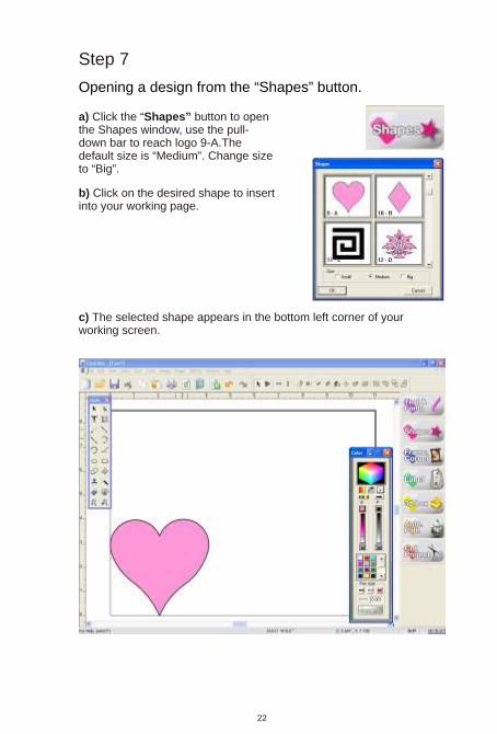
Step 7
Opening a design from the “Shapes” button.
b) Click on the desired shape to insert into your working page.
c) The selected shape appears in the bottom left corner of your working screen.
a) Click the button to open the window, use the pull-down bar to reach logo 9-A.The default size is “Medium”. Change size to “Big”.
“Shapes” Shapes
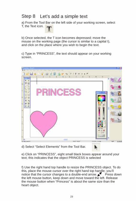
Step 8 Let’s add a simple texta) From the Tool Bar on the left side of your working screen, select T, the Text icon.
b) Once selected, the T icon becomes depressed; move the mouse on the working page (the cursor is similar to a capital I), and click on the place where you wish to begin the text.
c) Type in “PRINCESS”, the text should appear on your working screen.
d) Select “Select Elements” from the Tool Bar.
e) Click on “PRINCESS”, eight small black boxes appear around your text; this indicates that the object PRINCESS is selected
f) Use the right hand top handle to resize the PRINCESS object. To do this, place the mouse cursor over the right hand top handle; you’ll notice that the cursor changes to a double-end arrow. Press down the left mouse button, keep down and move toward the left. Release the mouse button when “Princess” is about the same size than the heart object.
23

h) By using the Select Element tool, move and resize objects on your screen in order to obtain the appearance of our drawing.
i) In this training course, we did not configure the cutter. Cutter configuration and setup is well documented and explained. However, if you have a printer you can print your drawing immediately.
Accessing the Cutter configuration page
Your cutter is configured and cut, your cutter is turned on and ready to run. For more details on the Cutting Control Panel see the chapter.
Click on the “Cut Project” icon, this will open the Cutting Control Panel.
24
g) When you place the mouse cursor over a selected object like “PRINCESS”,the cursor change to an X with arrows symbol. When it appears, click and drag the selection near the top of the heart object.

If your cutter cannot handle the speed and pressure parameters, you must configure directly on the cutter the speed and the pressure. However, you can use as a starting point the values suggested for the selected media.
25
Cutting panel shown when you use a cutter like Craft ROBO, Silhouette or Xyron; these cutters are identical.
For our first project we shall use the minimum of tools shown in the cutting control panel and we shall cut a standard letter-size paper used with your printer.
2 3
1
1- Select your media type: Select lightweight print paper
2-Tool: Depending on what media type you selected, different colored nooses may appear. The suggested tool has a blue nose.
3-Pressure & Speed: Parameters suggested to cut selected media. Refer to your cutter.

26
4- Landscape: Select landscape because the page orientation was in landscape.
5- Cut Project: Verify your cutter, if everything is right click the “Cut Project” button.
4
5
Congratulations, you have just finished your first project. It is important to watch the video or DVD supplied with your system; our Web site is another source of information and training.
To save your work, go to Document Bar, File, Save this opens the “Save as” menu. Always save your work in the same directory.

b) From the Functions Tool Bar, click on “Text & Fonts”.
a) Click the Select Elements tool from the Tool Bar and click on the “Princess” object to select it.
We are ready to begin part 2 of the training.
The Save or Save as menu.
c) The Fonts Window appear on your working screen.
Changing the font
27
Chapter 3: Making an advanced project (tutorial)

28
From the Fonts window you can view and select your font. For this project we used a FunTime font named “Dom Casual Bold” to access this font you can use the pull-down bar or type in the first few letters of your font name to locate it quickly.
To show your text in the Fonts screen you must select your text and click the Text & Fonts ; if any text is selected before clicking the Text & Fonts use the text box to type directly a new text.
buttonbutton
1
1
Step 9 Copy and paste an object or duplicate an object.
a) Select from the Tool Bar the Select Elements tool.
b) Click on “Heart shape”, eight small black boxes appear around the object: this indicates that the object is selected.
c) Select the Copy tool from the Document Bar.
d) Select the Paste tool from the Document Bar.
e) The result is that an identical copy is placed over the original heart logo.You can obtain the same result by using shortcuts on the keyboard (Ctrl+C) to copy and (Ctrl+V) to paste. Another great way is (Alt+D).

Step 10 Moving an object or the duplicated object.
b) Move the mouse cursor over the heart, click the left mouse button, release the mouse button, then click and keep the left button pushed down and move. You have just moved the heart selected copy.
a) Move the mouse cursor over the top right side handle of the heart that you have just moved; if your cursor is on the handle, its shape has changed and shows 2 small arrows. Click and keep the left mouse button down and move downward to the left, the heart decreases in size, move until the height of the heart is about the height of the lettering, then release the mouse button.
b) Move the mouse cursor over the rescaled heart, click the left mouse button, release it, then click and keep the pushed down left button and move over the P letter so it overlaps as shown on the picture.
a) The Select Element Tool is selected. If it is not selected, reselect it from the Tool Bar.
c) Your screen now shows two hearts.
Step 11 Rescale an object and move it.
Step 12 Hiding or removing the fill color.
As you can see it the border is black and the fill color is pink. The selected object is the heart, and our palette shows that the brush color is pink and that the pen color is black. To hide the pink colour (brush) just click the X at the bottom of the palette, the X will display in red and the colour of the selected heart disappears. Repeat the same procedure for the lettering. Select PRINCESS and click on the X for the brush color.
It is not necessary to hide the fill colour of an object; this way, you can visualize what you are doing.
29

Step 13 Welding 2 objects - Heart with PRINCESS
Use the Select Elements tool, move the mouse cursor over the heart, click the left mouse button, release it, then click and keep the left button pushed down and move. Move the heart selected to position it so that there is a good overlap of both surfaces.Now you need to select both objects. Use the Select Elements tool to create a box around the heart and around the lettering as shown on the illustration, release the mouse button.
Once the two objects are selected, click the Welding tool from the Tool Bar on the left side of the working screen.
The welding operation may take a few seconds; you will be able to see that the overlapping lines of your heart and letter P have disappeared.
30

Step 14 Distortion Heart weld to PRINCESS
d) Parameters used: 1) Use Form 2) Box with lines 3) Keep lines 4) Number of points = 8 This generates the drawing shown.
e) You can use the Select Elements tool to move the center handles and obtain bigger letters. When finished click on “Apply”
c) Dashed lines with eight square handles surround your selection.
a) Select the Select Element tool, click on the Heart & Princess object to select it; eight black handles appears.
b) From the Tool Bar select the Distortion tool, this open the Distortion window.
Move Up
Move Down
31
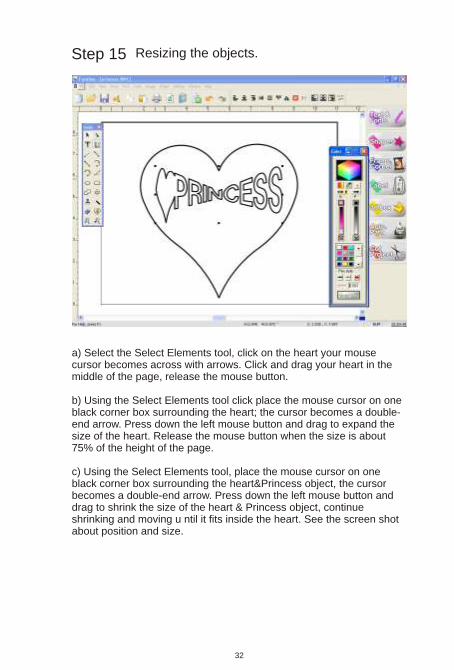
Step 15 Resizing the objects.
a) Select the Select Elements tool, click on the heart your mouse cursor becomes across with arrows. Click and drag your heart in the middle of the page, release the mouse button.
b) Using the Select Elements tool click place the mouse cursor on one black corner box surrounding the heart; the cursor becomes a double-end arrow. Press down the left mouse button and drag to expand the size of the heart. Release the mouse button when the size is about 75% of the height of the page.
c) Using the Select Elements tool, place the mouse cursor on one black corner box surrounding the heart&Princess object, the cursor becomes a double-end arrow. Press down the left mouse button and drag to shrink the size of the heart & Princess object, continue shrinking and moving u ntil it fits inside the heart. See the screen shot about position and size.
32
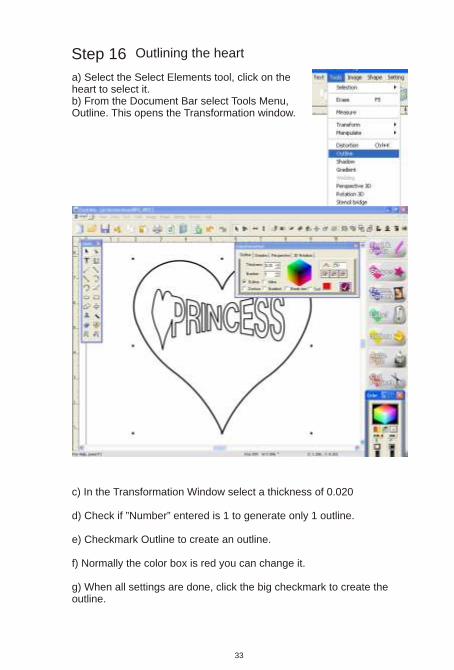
Step 16 Outlining the heart
a) Select the Select Elements tool, click on the heart to select it.b) From the Document Bar select Tools Menu, Outline. This opens the Transformation window.
c) In the Transformation Window select a thickness of 0.020
d) Check if ”Number” entered is 1 to generate only 1 outline.
e) Checkmark Outline to create an outline.
f) Normally the color box is red you can change it.
g) When all settings are done, click the big checkmark to create the outline.
33

When finished, click the X of the red square to close the Transformation window.
Step 17 Using scissors to modify the outline.
To transform the outline into a fancy contour we shall use scissors.
c) Under the Color Palette, select the Scissors tool.
b) We need to select the outline only. Still using the Select Elements tool, click on the outline, you will see the eight handles showing selection.
a) We need to select the outline only; to make this step easier, we need to see only lines without fill color. To do this, use the Wire Frame function. From the Document Bar, expand the View menu expand and activate Wire Frame.
34

d) A new Transformation window will appear, from the top tabs select “Scissors”.
e) Using the pull-down bar, select the third scissor model by clicking on it.
f) Using the slider to change the size of your scissor model, move it to about 20% of the range.
g) Click the “Apply” button.
h) When finished, click the X of the red square to close the Transformation window.
i) Since we are in wire frame, we cannot see any fill and pen colors. To return to normal view or deactivate the Wire Frame mode; from the Document Bar, expand the View menu and uncheck wire frame.
35

36
i) Returning in the normal view mode you can see your drawing clearly or hide one or several elements of the drawing. Do not worry, everything is there hidden under, while the biggest object is on top of the pile and its fill color hides the other objects.
j) Your screen contains 3 objects:- The smallest object is the heart welded to the text.- The second object is the heart- The third object is largest, which is the modified outline using scissors.
k) In normal view mode, you see one of these two screens:
l) The left drawing shows everything. However, if you obtain the drawing on the right you didn't do anything wrong. The objects are hidden behind the heart, and the fill colour is hiding the objects
m) To reveal the hidden objects you first need just to select the scissors outline. Use the Select Elements tool and click anywhere on the screen to unselect objects.n) Still using the Select Elements tool, click on the red border of the scissors outline; this selects the clicked object, showing eight handles around your selection.o) Now you can use one of these methodsp) Click the X in the left color bar in the Color Palette. The X becomes red, and this removes the red fill color that is hiding your drawing.q) The other way is to change the position of the biggest object hiding the small objects.r) Use the Select Elements tool and click anywhere on the screen away to unselect objects.s) Still using the Select Elements tool, click on the red border of the scissors outline; this selects the clicked object showing eight handles around your selection.

t) From the Document Bar, expand the Shape menu, select the sub menu Order and select To back.
Now you master all the functions needed to create big projects; your drawing is in the centre of the page, but it maybe too large, and its position is not right to cut or to printt. To select all objects on the screen press Ctrl + A from your keyboard and move it to the left hand bottom corner. The drawing must fit completely inside your page. To resize your drawing, use the right hand top handle and drag it in the center of the design to make it smaller.
37

Chapter 4: Know the tools.
Cutting mat
Blade holder with nooses
Because FunTime scrapbooking software is used with many cutters, it is important that the user possesses some knowledge common to all systems:
Cutting mat or carrierBlade holder with noosesBlade holder with adjustable nooseBlade typeCutting mediaMedia thicknessHow to evaluate the thicknessHow to adjust the blade tipWhen to replace the blade
It is necessary to use a cutting mat every time you cut a media without backup paper or film. The cutting mat prevents the blade from damaging the cutter, and keeps the cut media pieces in place.Before to use, remove the protective sheet from your mat and set it aside, you will use this sheet to store your mat.
When to replace your mat.1- Your mat no longer holds media or paper effectively.2- Your design cuts correctly in some places but not everywhere.3- Your mat is warped, heavily scored, has dirt on the surface...4- Even if using a new blade the cutting quality is poor.
Blade holder with adjustable noose
The blade has a small ball bearing in the bottom and the tips are used to adjust the cutting depth.
Blue cap = 0,1mm = 4 mils.Yellow cap = 0,2mm = 8 mils.Red cap = 0,3mm = 12 mils.
The blade tip length is completely adjustable; just screw or unscrew the adjustment then lock it when done.
Blade angle = 45 and 60 degrees.
Blade angle = 45 degrees.
38

Media thickness
How to evaluate the thickness
How to adjust the blade tip
When to replace the blade
Cutting media
Blade type
The normal blade angle is 45 degrees, but you can also use blades of 35, 60 and 70 degrees to cut the other media.
A large variety of media can be cut. Before proceeding, test the cut parameters on a small sample, use the minimal speed and the adequate pressure. The blade has to exceed the thickness of the paper by about 30%. Consult the media table to know the suggested parameters.
Estimate the thickness of your media. Available media are calibrated and standardized. However you can estimate by comparing the thickness of your media with the thickness of a media known as the common printer paper. Consult the media table.
The blade has to exceed by about 30 % the thickness of the paper. Using the media to be cut, place a scrap on a hard surface, maintaining the blade holder and blade adjusted, and simulate by hand the cutting motion a small square or rectangle.
Your cut quality suddenly gets worseYou will have to increase more and more the blade pressure to obtain a clean cut.The corners and tight turns do not cut cleanly, the paper lifts up at the corners.
We categorize the media in 4 categories:A) Thin or filmB) Strong paperC) CardboardD) Thick or Chipboard
< 0,1mm or <4mils < 0,2mm or <8mils < 0,3mm or <12mils0,3mm (12mils) between 0,75mm (30mils)
39

1) Before proceeding to the configuration this information will be necessary1) Cutter brand name and model2) Type of connection3) USB driver4) USB cable or cable supplied with cutter.
Chapter 5: Cutter configuration and testing
Run the FunTime software and from the Settings menu, click on Plotter Codes
Then from the setup plotter window click on Add/Remove. Locate your plotter model, select it and click on the arrow to place the plotter in the active window to the right. Finally click OK and Accept/Save
40

Click the OK button to close the USB port selection window and click the Accept/Save button.
If your cutter is configured to USB port, select the proper USB printer driver installed.
41
if your printer USB driver is not in the list?What to do...

Draw a square or a rectangle on the working page.
Click on the Cut Project icon, this will open the Cutting Control Panel Press the Start button.
To test the equipment:
7
42
If the printer driver does not appear in the list.
1) Close the window “Select USB plotter” by clicking the “Cancel” button or “X”2) Close the window “Setup plotters” by clicking the “Cancel” button or “X”
1) Connect the computer and the cutter using the USB cable, turn the cutter power On.
2) If Windows detects a new peripheral it will generally ask for the printer driver; this driver is provided with your cutter.
3) Install the driver. If the driver is already installed, Windows will complete the installation.
4) Begin again the cutter configuration procedure, this time the USB driver will be visible select it.

2
8
9
4
7
3
6
1
5
1- Select your media type: Using the arrow expand a drop down menu showing several preset media, choose the media looks the most like your material.
2-Tool: Depending on what media type is selected in step 1, a tool with different colored end caps may appear.
3-Pressure: After the selection of a media type in the step 1, a pressure value is suggested using the sliding button you can modify the pressure.
4-Speed: After the selection of a media type in the step 1, a speed value is suggested using the sliding button you can modify the speed.
5-#Pass: The number of times the cutter is going to cut the same object. To cut thick media like chipboard, you can use two or three passes.
6-Material: Maximum cutting width allowed, you configure a working screen bigger than the maximum cutting page size, FunTime generates a cutting panel on the screen.
7-Knife Offset: Use value by default attributed to the media you can modify this value if you use thick media or blades of different angles.
8-Color Bar: Shows all the object colors you can cut on your screen, allows to select one or several colors to be cutted.
9-Add Media: You can create custom settings for media or add your favorite settings.
To open the control cutting panel, click the “Cut Project” button or press F10 from your keyboard.
More on Control Cutting Panel
43

15
13
11
16- Landscape: Select landscape because our page orientation was in landscape, unselect it if you work in portrait orientation.
12- Send to file: This function is for technical support.
14- Rotate: Rotates your entire work.
15- Weeding: Cut a square around your drawing, useful to cut vinyl stickers.
Can be adjusted from “Options”.
11- Advance: When cutting is done your page will go out automatically. Unselect this function if you have to use different tools on the same page or if your work is in registration mode.
13- Mirror: Mirror function can be done inside the software. Selected from the Control Cutting Panel, this function mirrors your entire work. Useful when you are cutting iron-on transfer material.
10- Selected object: Displays and cuts one or many selected objects. Select object(s) before you checkmark “Selected object”
10
12
14
15
Section 2 Advance options
44

17- Cut Project: Verify your cutter, if everything is correct click the “Cut Project” button.
18- Return: Closes the Cutting Control Panel without cutting your project.
19- Stop cutting: Click this button to stop cutting your project before it is finished. May not stop your cutter immediately.
20- Options: Opens a window for additional setup.
21- Help: Shows help on the Cutting Control Panel.
22- Arrows: Active only for certain cutters use arrows to move the cutter head and position over the media. Same action as using displacement arrows on the cutter.
23- Mark reading: For the cutters provided with optical cropmarks detection, or cutters using either a mechanical registration device or laser alignment.
24- Width Height : Measured distance between cropmarks.
Section 3 Media alignement
17
18
19
20
21
22
23
24
45

Chapter 6: Graphics source and Vectorization.
1- Import from a saved graphics file.2- Copy and paste graphics.3- Scanning graphics.
When digitizing your image - use the scanner functions to enlarge the image as much as possible. The larger the image, the better the conversion will be.You can scan in color at 256 colors, 8 bit, 16 bit, or 24 bit.
Parameters to use : - Black or Color drawing (Solid colors only) - Enlarge the selected zone as much as possible 200 to 800 % - Scan using 200 or 300 dpi
1- You can import graphics into you Funtime software by using your Import button from the document bar. You can use File Menu, Import, Image. (Ctrl + I)
2- From another program showing a graphic on the screen, or from a Web site, you can use the right mouse button to copy the selected graphic and paste it afterward on your Funtime scrapbooking working screen.. Use the right mouse button to copy or paste a graphic or use the keyboard (Ctrl + C) to copy and (Ctrl + V) to paste.
3- From a scanner, place your graphic in the scanner.a) From the file menu, select the source and locate your scanner you will only need to do this the first time you use a scanner.b) Select File and select Scanc) Your scanner menu should appear.
46

To begin the automatic color vectorization
Step 1: Import an image or scan an image.
Step 2: If your image shows gaps, use our interpolation tool, allowing to increase the size of your image.
The quality of your image will affect the results. An image taken from a Web site is often of poor quality, and most of the time is too small to generate a good conversion.If your image presents gaps:1) Size of the image is lower than 2 inches.2) Visual quality is 72 or 96 dpi3) Image shows stairlike borders.
47

From the Image Menu select Vectorization / Automatic Enhance Curve
Or simply,click Auto Path button.
The resizing (blow up) factor of the image maybe from 4 to 20 times the original size. If your image size is 1/8 inch, a factor of 20 will be normal.
Step 3: To begin the automatic color vectorization.
48

Step 4 Consists in analyzing image to be converted. We can only trace in Bézier curves, we can force the quantity of curves and arcs, we can force the creation of sharp corners and lines.
Detect Intensity: Allows to increase or to remove colors or tints or allows to increase the tint or to increase strength of one or several colors.
Make Vectorization: The magic wand allows to vectorize the drawing.
Apply on Selection: After vectorization you can select objects. The selected objects can be transformed into curves or into segments to obtain square corners.
Color Resolution: Allows to reduce the number of bits by successive steps from 24 bits to 1 bit per pixel. This tool transforms an image in a black and white picture.
1
1
2
2
3
4
3
4
Step 1
49

Three easy steps.
Visually this image contains a strong percentage of curves. Let us use “Enhanced curve”.
Use the “Detect Intensity” tool and use the first slider to increase or decrease the intensity of colors.
Use the “Color Resolution” tool and use the down arrow to select 1 bit, decreasing colors to 1 bit pixel ( Black & White). A black and white image generates better quality during vectorization.
Use these parameters:Bits per pixel = 1Dither method = NonePalette = Fixed PaletteColor Order = Blue-Green-Red.
50
Display mode:1:1 real scaleFull screen( see full image)

Use the “Magic Wand” and click on the image to be converted.
After vectorization, objects can be modified by using others conversion parameters. If a visual analysis of vectorized objects shows that one or more converted objects need squared corners, only use the “Select Elements” tool, select one or more objects, click the option “Enhanced corner” and click the button “Apply on selection”.
“Enhanced corner” forces objects to display sharp corners; if you use “Enhance curve” it forces objects to display curves, which means sharp corners become rounded.
Also good to vectorize text.51
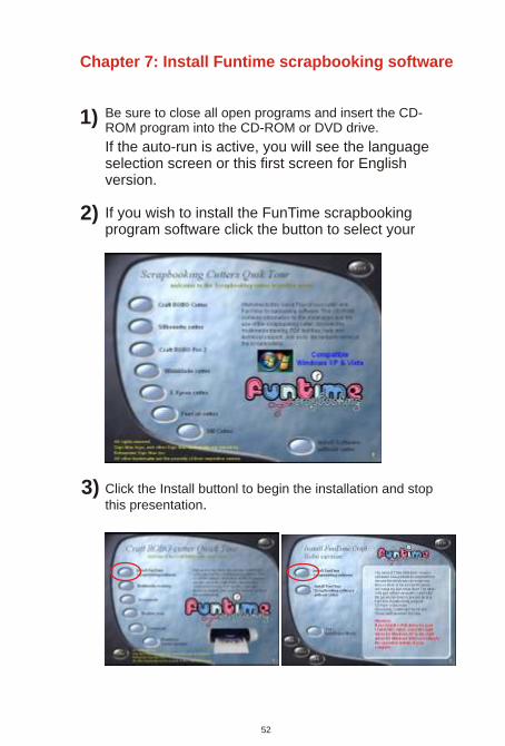
Be sure to close all open programs and insert the CD-ROM program into the CD-ROM or DVD drive.
If the auto-run is active, you will see the language selection screen or this first screen for English version.
If you wish to install the FunTime scrapbooking program software click the button to select your
52
Click the Install buttonl to begin the installation and stop this presentation.
1)
2)
3)
Chapter 7: Install Funtime scrapbooking software

4) If the Setup.exe has been successfully selected, the following picture will be displayed. Select the language and click Next to continue
5) Click the radio button “I accept the terms of the license
agreement” and click Next button.
6) When the installation is complete, click the button “Finish” and Register via Internet or register via a registration card and mail.
7) Make sure you install the Windows redistributables, this takes approximately a minute.
53

A) Insert the CD-Rom Program in the CD-Rom drive, double-click on My Computer icon, then from the dialog box, double-click the CD-Rom icon.
If it doesn’t start, the auto-run is deactivated; use one of the following two methods.
OR
Start MyComputer
Double click on your CDor DVD drive.
Double-click your CD or DVD drive, double-click the file Autorun.exe. This will start the presentation to continue the installation.
B Your FunTime program CD-Rom must be in your CD or DVD drive.- Click on Start in the toolbar and choose RunType d:\Autorun.exe in the dialog box and press Return.
The D:\ drive is where your CD-ROM is located. If, the letter for your CD-ROM drive is not D, type in the appropriate letter. Follow on-screen instructions to finish installation, accept default.
54

You can install the security key anytime, no driver to install or search, just place the security key (dongle) in a USB port. This can be done anytime before running the program.
Before running the program:To run the program you need two free USB ports on your computer; one to install the security key (dongle), and one to use the craft cutter, if you use a USB cable or adaptor.
1) Proceed to install the FunTime software2) Install the USB key - see step 23) Connect the USB cable to cutter and computer, power on the cutter, Windows detects a new hardware and asks for the USB driver. If you use a CraftROBO, Silhouette, WishBlade and Xyron you can cancel the installation of this driver because the driver is already embedded in the FunTime software. If you use a serial cutter and serial mode no driver is needed to install. If you use a serial adapter, install the serial adapter with the serial cable; you must install the USB driver supplied with the adapter. Any USB cutter requires a USB driver. Restart the computer before configuring the software4) Run the FunTime program, configure your craft cutter. From the list select your model and configure the USB port. Restart your computer. If you use a serial adapter configure in COM mode.
1
2
Security key installation (dongle).
55

8
7
6
5
4
3
2
1
1. Transform: Indicates which tool is selected and used.
2. Position as X and Y: Represents the position of the selected object. On the photo we see a position giving to X a position of 2.5 and giving to Y a position of 5. The left bottom screen corner represents the position 0,0. You can modify these values by typing the desired values in the window. Scroll buttons can be used.
3. Angle: This represents the rotation angle in degrees that you wish to rotate an object or the inclination (slant) angle.
4. According to: You can select the rotation axis or the mirror plan to make a transformation.
5. Increments:This represents the rotation angle in degrees that you wish to rotate an object or the inclination (slant)
6. Cancel: This cancels (undo) the last action.
7. Duplicate: Before selecting “Apply” you can select “Duplicate” to create a copy of any selected object or groups.
8. Apply: Apply the selected transformation to the selected objects or groups.
Press the letter H from your keyboard.
Note: The transformation tool measures the selected object, it is the measure of the box of the selected objects. Not recommended for text height.
The transformation tool is specially used to modify or to compare position, height, width, condensation, slant, mirror effects, rotation and engraving functions of any selected objects or groups. This exceptional tool will facilitate your work.
Chapter 8: Transformation window
56

Pa
pe
r a
nd
ca
rd b
oa
rd p
ara
me
ters
Ca
no
n P
ho
to P
ap
er
Plu
s 1
0.5
mil
(0,2
7m
m)
27
0 g
/m2
14
9 lb
sP
ink
no
ose
or
#4
P=
27
S=
12
pa
sse
s
2 p
ass
es
4 m
il (0
.10
mm
)2
2 lb
sB
lue
no
ose
Cra
ft R
OB
OY
ou
r S
etu
p
P=
10
S=
5P
=
P=
P=
P=
P=
P=
P=
P=
P=
P=
S=
S=
S=
S=
S=
S=
S=
S=
S=
S=
P=
S
=
P=
S
=
P=
S
=
60
de
g O
=4
0
60
de
g O
=4
0
45
de
g O
=2
0
Pla
in p
ap
er
Me
dia
Typ
eT
hic
kne
ss
We
igh
tW
eig
ht
Ca
pF
orc
eS
pe
ed
Fo
rce
Sp
ee
d
P=
25
S=
2P
ink
no
ose
or
#4
45
lbs
8.5
mil
(0.2
2m
m)
Ca
no
n M
atte
Ph
oto
pa
pe
r
Pla
in p
ap
er
P=
10
S=
5Y
ello
w n
oo
se9
0g
/m2
24
lbs
5 m
il (0
.13
mm
)
P=
22
S=
3
Pin
k n
oo
seo
r #
49
,0 m
il (0
,23
mm
)C
an
son
G/m
2lb
s
Do
mta
r C
ard
Sto
ck9
,5 m
ils (
0,2
4m
m)
110
lbs.
19
9 g
/m2
Pin
k n
oo
seo
r #
4P
=2
7 S
=2
P=
24
S=
1
P=
10
S=
5
P=
9 S
=3
P=
S
=
Pin
k n
oo
seo
r #
4
No
ose
#4
No
ose
#4
No
ose
#4
Ble
u n
oo
se
Ble
u n
oo
se
Ble
u n
oo
se
18
0 g
/m2
99
lbs.
8 m
il (0
,20
mm
)
2 m
il (0
,05
mm
)
3 m
il (0
,08
mm
)
12
,5 m
il (0
,32
mm
)
Bro
chu
re &
Fly
er
pa
pe
rd
ou
ble
-sid
ed
glo
ss
Vin
yl
Me
talli
c S
ilve
r
Me
talli
c G
old
Ba
zill
Ch
ipb
oa
rd
Ch
ipb
oa
rd
O=
15
# # #
21
mil
(0,5
3m
m)
31
mil
(0,7
5m
m)
57
Chapter 9: Paper and media parameters