fundamentals of protection practice
TRANSCRIPT

7/23/2019 Fundamentals of Protection Practice
http://slidepdf.com/reader/full/fundamentals-of-protection-practice 1/11
Alstom Grid 2-1
Chapter 2
Fundamentals of Protection Practice
2.1 Introduction2.2 Protection Equipment
2.3 Zones of Protection
2.4 Reliability
2.5 Selectivity
2.6 Stability
2.7 Speed
2.8 Sensitivity
2.9 Primary and Back-up Protection
2.10 Relay Output Devices
2.11 Tripping Circuits
2.12 Trip Circuit Supervision
2.1 INTRODUCTION
The purpose of an electrical power system is to generate and
supply electrical energy to consumers. The system should be
designed to deliver this energy both reliably and economically.
Frequent or prolonged power outages result in severe
disruption to the normal routine of modern society, which is
demanding ever-increasing reliability and security of supply.
As the requirements of reliability and economy are largely
opposed, power system design is inevitably a compromise.
A power system comprises many diverse items of equipment.
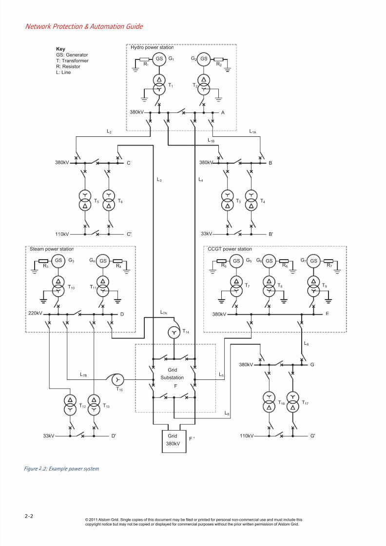
Figure 2.1 illustrates the complexity of a typical power stationFigure 2.2 shows a hypothetical power system.
Figure 2.1: Modern power station
© 2011 Alstom Grid. Single copies of this document may be filed or printed for personal non-commercial use and must include this
copyright notice but may not be copied or displayed for commercial purposes without the prior written permission of Alstom Grid.
7/23/2019 Fundamentals of Protection Practice
http://slidepdf.com/reader/full/fundamentals-of-protection-practice 2/11
Network Protection & Automation Guide
2-2
Figure .2: Example power system
R1
GS G1
T1
G2
T2
R2
GS
A380kV
Hydro power station
380kV B
L1A
L1B
380kV C
L2
L3 L4
T4
B'
T3
33kV
T5 T6
110kV C'
380kV
CCGT power station
T8T7
E
G5
R5
GS G6 GSR6
GSG7
R7
T9
D220kV
Steam power station
R3
GSGS
T10 T11
G3 G4
R4
L7A
Grid
Substation
T14
T15
L7B
33kV D'
T12 T13
110kV
380kV
L8
G'
G
T16 T17
L5
Grid
380kVF '
F
L6
Key
GS: Generator
T: Transformer
R: Resistor
L: Line
© 2011 Alstom Grid. Single copies of this document may be filed or printed for personal non-commercial use and must include this
copyright notice but may not be copied or displayed for commercial purposes without the prior written permission of Alstom Grid.

7/23/2019 Fundamentals of Protection Practice
http://slidepdf.com/reader/full/fundamentals-of-protection-practice 3/11
Chapter 2 Fundamentals of Protection Practice
2-3
Figure 2.3: Onset of an overhead line fault
Many items of equipment are very expensive, and so the
complete power system represents a very large capital
investment. To maximise the return on this outlay, the system
must be utilised as much as possible within the applicable
constraints of security and reliability of supply. More
fundamental, however, is that the power system should
operate in a safe manner at all times. No matter how well
designed, faults will always occur on a power system, and
these faults may represent a risk to life and/or property. Figure
2.3 shows the onset of a fault on an overhead line. The
destructive power of a fault arc carrying a high current is very
large; it can burn through copper conductors or weld together
core laminations in a transformer or machine in a very short
time – some tens or hundreds of milliseconds. Even away
from the fault arc itself, heavy fault currents can cause
damage to plant if they continue for more than a few seconds.
The provision of adequate protection to detect and disconnect
elements of the power system in the event of fault is therefore
an integral part of power system design. Only by doing this
can the objectives of the power system be met and the
investment protected. Figure 2.4 provides an illustration of the
consequences of failure to provide adequate protection. This
shows the importance of protection systems within the
electrical power system and of the responsibility vested in theProtection Engineer.
Figure 2.4: Possible consequence of inadequate protection
2.2 PROTECTION EQUIPMENT
The definitions that follow are generally used in relation to
power system protection:
Protection System: a complete arrangement of
protection equipment and other devices required to
achieve a specified function based on a protection
principle (IEC 60255-20)
Protection Equipment: a collection of protection
devices (relays, fuses, etc.). Excluded are devices such
as Current Transformers (CTs), Circuit Breakers (CBs)
and contactors
Protection Scheme: a collection of protection
equipment providing a defined function and including
all equipment required to make the scheme work (i.e.
relays, CTs, CBs, batteries, etc.)
In order to fulfil the requirements of protection with the
optimum speed for the many different configurations,
operating conditions and construction features of power
systems, it has been necessary to develop many types of relay
that respond to various functions of the power system
quantities. For example, simple observation of the fault
current magnitude may be sufficient in some cases but
measurement of power or impedance may be necessary in
others. Relays frequently measure complex functions of thesystem quantities, which may only be readily expressible by
mathematical or graphical means.
Relays may be classified according to the technology used:
electromechanical
static
digital
numerical
The different types have varying capabilities, according to the
limitations of the technology used. They are described in moredetail in Chapter 7.
© 2011 Alstom Grid. Single copies of this document may be filed or printed for personal non-commercial use and must include this
copyright notice but may not be copied or displayed for commercial purposes without the prior written permission of Alstom Grid.

7/23/2019 Fundamentals of Protection Practice
http://slidepdf.com/reader/full/fundamentals-of-protection-practice 4/11
Network Protection & Automation Guide
2-4
In many cases, it is not feasible to protect against all hazards
with a relay that responds to a single power system quantity.
An arrangement using several quantities may be required. In
this case, either several relays, each responding to a single
quantity, or, more commonly, a single relay containing several
elements, each responding independently to a different
quantity may be used.
The terminology used in describing protection systems and
relays is provided in Appendix A. Different symbols for
describing relay functions in diagrams of protection schemes
are used, the three most common methods (IEC, IEEE/ANSI
and IEC61850) are provided in Appendix B.
2.3 ZONES OF PROTECTION
To limit the extent of the power system that is disconnected
when a fault occurs, protection is arranged in zones. The
principle is shown in Figure 2.5. Ideally, the zones ofprotection should overlap, so that no part of the power system
is left unprotected. This is shown in Figure 2.6(a), the circuit
breaker being included in both zones.
GS
Feeder 2Feeder 1 Feeder 3Zone 6
Zone 5 Zone 7
Zone 4
Zone 3
Zone 2
Zone 1
Figure 2.5: Division of power systems into protection zones
For practical physical and economic reasons, this ideal is not
always achieved, accommodation for current transformersbeing in some cases available only on one side of the circuit
breakers, as shown in Figure 2.6(b). In this example, the
section between the current transformers and the circuit
breaker A is not completely protected against faults. A fault at
F would cause the busbar protection to operate and open the
circuit breaker but the fault may continue to be fed through the
feeder. If the feeder protection is of the type that responds
only to faults within its own zone (see section 2.5.2), it would
not operate, since the fault is outside its zone. This problem is
dealt with by intertripping or some form of zone extension, to
ensure that the remote end of the feeder is also tripped. These
methods are explained extensively in chapters 11 and 12.
Feeder
protection
Feeder
protection
Busbar
protection
Busbar
protection
(a) CTs on both sides of circuit breaker
(b)CTs on circuit side of circuit breaker Figure 2.6: CT locations
The point of connection of the protection with the power
system usually defines the zone and corresponds to the
location of the current transformers. Unit type protection
results in the boundary being a clearly defined closed loop.
Figure 2.7 shows a typical arrangement of overlapping zones.
Figure 2.7: Overlapping zones of protection systems
Alternatively, the zone may be unrestricted; the start will be
defined but the extent (or ‘reach’) will depend on
measurement of the system quantities and will therefore be
subject to variation, owing to changes in system conditions
and measurement errors.
© 2011 Alstom Grid. Single copies of this document may be filed or printed for personal non-commercial use and must include this
copyright notice but may not be copied or displayed for commercial purposes without the prior written permission of Alstom Grid.

7/23/2019 Fundamentals of Protection Practice
http://slidepdf.com/reader/full/fundamentals-of-protection-practice 5/11
Chapter 2 Fundamentals of Protection Practice
2-5
2.4 RELIABILITY
The need for a high degree of reliability has already been
discussed briefly. Reliability is dependent on the following
factors:
incorrect design/settings
incorrect installation/testing
deterioration in service
2.4.1 Design
The design of a protection scheme is of paramount
importance. This is to ensure that the system will operate
under all required conditions, and refrain from operating when
so required. This includes being restrained from operating for
faults external to the zone being protected, where necessary.
Due consideration must be given to the nature, frequency and
duration of faults likely to be experienced, all relevantparameters of the power system and the type of protection
equipment used. Of course, the design of the protection
equipment used in the scheme is just as important. No
amount of effort at this stage can make up for the use of badly
designed protection equipment.
2.4.2 Settings
It is essential to ensure that settings are chosen for protection
relays and systems which take into account the parameters of
the primary system, including fault and load levels, and
dynamic performance requirements, etc. The characteristics ofpower systems change with time, due to changes in loads,
location, type and amount of generation, etc. Therefore,
setting values of relays may need to be checked at suitable
intervals to ensure that they are still appropriate. Otherwise,
unwanted operation or failure to operate when required may
occur.
2.4.3 Installation
The need for correct installation of protection systems is
obvious, but the complexity of the interconnections of many
systems and their relationship to the remainder of the systemmay make checking the installation difficult. Site testing is
therefore necessary. Since it will be difficult to reproduce all
fault conditions correctly, these tests must be directed towards
proving the installation itself. At the installation stage, the
tests should prove the correctness of the connections, relay
settings, and freedom from damage of the equipment. No
attempt should be made to ‘type test’ the equipment or to
establish complex aspects of its technical performance.
2.4.4 Testing
Testing should cover all aspects of the protection scheme,reproducing operational and environmental conditions as
closely as possible. Type testing of protection equipment to
recognised standards is carried out during design and
production and this fulfils many of these requirements, but it
will still be necessary to test the complete protection scheme
(relays, current transformers and other ancillary items). The
tests must realistically simulate fault conditions.
2.4.5 Deterioration in Service
Subsequent to installation, deterioration of equipment will take
place and may eventually interfere with correct functioning.
For example: contacts may become rough or burnt due to
frequent operation, or tarnished due to atmospheric
contamination, coils and other circuits may become open-
circuited, electronic components and auxiliary devices may fail,
and mechanical parts may seize up.
The time between operations of protection relays may be years
rather than days. During this period, defects may have
developed unnoticed until revealed by the failure of theprotection to respond to a power system fault. For this reason,
relays should be periodically tested in order to check they are
functioning correctly.
Testing should preferably be carried out without disturbing
permanent connections. This can be achieved by the provision
of test blocks or switches.
The quality of testing personnel is an essential feature when
assessing reliability and considering means for improvement.
Staff must be technically competent and adequately trained, as
well as self-disciplined to proceed in a systematic manner to
achieve final acceptance.
Important circuits that are especially vulnerable can be
provided with continuous electrical supervision; such
arrangements are commonly applied to circuit breaker trip
circuits and to pilot circuits. Modern digital and numerical
relays usually incorporate self-testing/diagnostic facilities to
assist in the detection of failures. With these types of relay, it
may be possible to arrange for such failures to be automatically
reported by communications link to a remote operations
centre, so that appropriate action may be taken to ensure
continued safe operation of that part of the power system andarrangements made for investigation and correction of the
fault.
2.4.6 Protection Performance
Protection system performance is frequently assessed
statistically. For this purpose each system fault is classed as
an incident and only those that are cleared by the tripping of
the correct circuit breakers are classed as 'correct'. The
percentage of correct clearances can then be determined.
This principle of assessment gives an accurate evaluation of
the protection of the system as a whole, but it is severe in its judgement of relay performance. Many relays are called into
© 2011 Alstom Grid. Single copies of this document may be filed or printed for personal non-commercial use and must include this
copyright notice but may not be copied or displayed for commercial purposes without the prior written permission of Alstom Grid.

7/23/2019 Fundamentals of Protection Practice
http://slidepdf.com/reader/full/fundamentals-of-protection-practice 6/11
Network Protection & Automation Guide
2-6
operation for each system fault, and all must behave correctly
for a correct clearance to be recorded.
Complete reliability is unlikely ever to be achieved by further
improvements in construction. If the level of reliability
achieved by a single device is not acceptable, improvement can
be achieved through redundancy, e.g. duplication ofequipment. Two complete, independent, main protection
systems are provided, and arranged so that either by itself can
carry out the required function. If the probability of each
equipment failing is x/unit, the resultant probability of both
equipments failing simultaneously, allowing for redundancy, is
x2. Where x is small the resultant risk (x
2) may be negligible.
Where multiple protection systems are used, the tripping
signal can be provided in a number of different ways. The two
most common methods are:
all protection systems must operate for a tripping
operation to occur (e.g. ‘two-out-of-two’ arrangement)
only one protection system need operate to cause a trip
(e.g. ‘one-out-of two’ arrangement)
The former method guards against false tripping due to
maloperation of a protection system. The latter method guards
against failure of one of the protection systems to operate, due
to a fault. Occasionally, three main protection systems are
provided, configure in a ‘two-out-of three’ tripping
arrangement, to provide both reliability of tripping, and security
against unwanted tripping.
It has long been the practice to apply duplicate protection
systems to busbars, both being required to operate to complete
a tripping operation. Loss of a busbar may cause widespread
loss of supply, which is clearly undesirable. In other cases,
important circuits are provided with duplicate main protection
systems, either being able to trip independently. On critical
circuits, use may also be made of a digital fault simulator to
model the relevant section of the power system and check the
performance of the relays used.
2.5 SELECTIVITY
When a fault occurs, the protection scheme is required to trip
only those circuit breakers whose operation is required to
isolate the fault. This property of selective tripping is also
called 'discrimination' and is achieved by two general
methods.
2.5.1 Time Grading
Protection systems in successive zones are arranged to operate
in times that are graded through the sequence of protection
devices so that only those relevant to the faulty zone complete
the tripping function. The others make incomplete operations
and then reset. The speed of response will often depend on the
severity of the fault, and will generally be slower than for a unit
system.
2.5.2 Unit Systems
It is possible to design protection systems that respond only to
fault conditions occurring within a clearly defined zone. This
type of protection system is known as 'unit protection'. Certain
types of unit protection are known by specific names, e.g.
restricted earth fault and differential protection. Unit
protection can be applied throughout a power system and,
since it does not involve time grading, it is relatively fast in
operation. The speed of response is substantially independent
of fault severity.
Unit protection usually involves comparison of quantities at the
boundaries of the protected zone as defined by the locations of
the current transformers. This comparison may be achieved by
direct hard-wired connections or may be achieved via a
communications link. However certain protection systemsderive their 'restricted' property from the configuration of the
power system and may be classed as unit protection, e.g. earth
fault protection applied to the high voltage delta winding of a
power transformer. Whichever method is used, it must be
kept in mind that selectivity is not merely a matter of relay
design. It also depends on the correct co-ordination of current
transformers and relays with a suitable choice of relay settings,
taking into account the possible range of such variables as
fault currents, maximum load current, system impedances and
other related factors, where appropriate.
2.6 STABILITY
The term ‘stability’ is usually associated with unit protection
schemes and refers to the ability of the protection system to
remain unaffected by conditions external to the protected zone,
for example through-load current and faults external to the
protected zone.
2.7 SPEED
The function of protection systems is to isolate faults on the
power system as rapidly as possible. One of the main
objectives is to safeguard continuity of supply by removingeach disturbance before it leads to widespread loss of
synchronism and consequent collapse of the power system.
As the loading on a power system increases, the phase shift
between voltages at different busbars on the system also
increases, and therefore so does the probability that
synchronism will be lost when the system is disturbed by a
fault. The shorter the time a fault is allowed to remain in the
system, the greater can be the loading of the system. Figure
2.8 shows typical relations between system loading and fault
clearance times for various types of fault. It will be noted that
phase faults have a more marked effect on the stability of thesystem than a simple earth fault and therefore require faster
© 2011 Alstom Grid. Single copies of this document may be filed or printed for personal non-commercial use and must include this
copyright notice but may not be copied or displayed for commercial purposes without the prior written permission of Alstom Grid.

7/23/2019 Fundamentals of Protection Practice
http://slidepdf.com/reader/full/fundamentals-of-protection-practice 7/11
Chapter 2 Fundamentals of Protection Practice
2-7
clearance.
System stability is not, however, the only consideration. Rapid
operation of protection ensures minimisation of the equipment
damage caused by the fault. The damaging energy liberated
during a fault is proportional to the time that the fault is
present, thus it is important that the protection operate asquickly as possible. Speed of operation must be weighed
against economy, however. Distribution circuits, which do not
normally require a fast fault clearance, are usually protected by
time-graded systems. On the other hand, generating plant
and EHV systems require protection systems of the highest
attainable speed and reliability, therefore unit systems are
normal practice.
Time
L o a d
p o w e r
Phase-earth
Phase-phase
Three-phase
Phase-phase-earth
Figure 2.8: Typical power/time relationship for various fault types
2.8 SENSITIVITY
Sensitivity is a term frequently used when referring to the
minimum operating level (current, voltage, power etc.) of
relays or complete protection schemes. Relays or protection
schemes are said to be sensitive if their primary operating
parameters are low.
With older electromechanical relays, sensitivity was considered
in terms of the measuring movement and was measured in
terms of its volt-ampere consumption to cause operation.
With modern digital and numerical relays the achievable
sensitivity is seldom limited by the device design but by its
application and associated current and voltage transformerparameters.
2.9 PRIMARY AND BACK-UP PROTECTION
The reliability of a power system has been discussed earlier,
including the use of more than one primary (or ‘main’)
protection system operating in parallel. In the event of failure
or non-availability of the primary protection some other means
of ensuring that the fault is isolated must be provided. These
secondary systems are referred to as ‘back-up protection
schemes’.
Back-up protection may be considered as either being ‘local’ or
‘remote’. Local back-up protection is achieved by protection
that detects an un-cleared primary system fault at its own
location, which then trips its own circuit breakers; e.g. time
graded overcurrent relays. Remote back-up protection is
provided by protection that detects an un-cleared primary
system fault at a remote location and then issues a trip
command to the relevant relay; e.g. the second or third zones
of a distance relay. In both cases the main and back-up
protection systems detect a fault simultaneously, operation of
the back-up protection being delayed to ensure that the
primary protection clears the fault if possible. Normally being
unit protection, operation of the primary protection will be fast
and will result in the minimum amount of the power system
being disconnected. Operation of the back-up protection will
be, of necessity, slower and will result in a greater proportion
of the primary system being lost.
The extent and type of back-up protection applied will naturally
be related to the failure risks and relative economic importance
of the system. For distribution systems where fault clearance
times are not critical, time delayed remote back-up protection
may be adequate. For EHV systems, where system stability is
at risk unless a fault is cleared quickly, multiple primary
protection systems, operating in parallel and possibly of
different types (e.g. distance and unit protection), will be used
to ensure fast and reliable tripping. Back-up overcurrent
protection may then optionally be applied to ensure that two
separate protection systems are available during maintenance
of one of the primary protection systems.
Back-up protection systems should, ideally, be completelyseparate from the primary systems. For example, a circuit
protected by a current differential relay may also have time-
graded overcurrent and earth fault relays added to provide
circuit breaker tripping in the event of failure of the main
primary unit protection. Ideally, to maintain complete
redundancy, all system components would be duplicated. This
ideal is rarely attained in practice. The following compromises
are typical:
Separate current transformers or duplicated secondary
cores are often provided. This practice is becoming less
common at distribution voltage levels if digital ornumerical relays are used, because the extremely low
input burden of these relay types allows relays to share
a single CT
Voltage transformers are not duplicated because of cost
and space considerations. Each protection relay supply
is separately protected (fuse or MCB) and continuously
supervised to ensure security of the VT output. An
alarm is given on failure of the supply and where
appropriate, unwanted operation of the protection is
prevented
Trip power supplies to the two protection types should
be separately protected (fuse or MCB). Duplication of
© 2011 Alstom Grid. Single copies of this document may be filed or printed for personal non-commercial use and must include this
copyright notice but may not be copied or displayed for commercial purposes without the prior written permission of Alstom Grid.

7/23/2019 Fundamentals of Protection Practice
http://slidepdf.com/reader/full/fundamentals-of-protection-practice 8/11
Network Protection & Automation Guide
2-8
tripping batteries and of circuit breaker trip coils may be
provided. Trip circuits should be continuously
supervised.
It is desirable that the main and back-up protections (or
duplicate main protections) should operate on different
principles, so that unusual events that may cause
failure of the one will be less likely to affect the other
Digital and numerical relays may incorporate suitable back-up
protection functions (e.g. a distance relay may also incorporate
time-delayed overcurrent protection elements as well). A
reduction in the hardware required to provide back-up
protection is obtained, but at the risk that a common relay
element failure (e.g. the power supply) will result in
simultaneous loss of both main and back-up protection. The
acceptability of this situation must be evaluated on a case-by-
case basis.
2.10 RELAY OUTPUT DEVICES
In order to perform their intended function, relays must be
fitted with some means of providing the various output signals
required. Contacts of various types usually fulfil this function.
2.10.1 Contact Systems
Relays may be fitted with a variety of contact systems for
providing electrical outputs for tripping and remote indication
purposes. The most common types encountered are as
follows:
Self-reset: The contacts remain in the operated
condition only while the controlling quantity is applied,
returning to their original condition when it is removed
Hand or electrical reset: These contacts remain in the
operated condition after the controlling quantity has
been removed.
The majority of protection relay elements have self-reset
contact systems, which, if so desired, can be modified to
provide hand reset output contacts by the use of auxiliary
elements. Hand or electrically reset relays are used when it is
necessary to maintain a signal or lockout condition. Contactsare shown on diagrams in the position corresponding to the
un-operated or de-energised condition, regardless of the
continuous service condition of the equipment. For example,
an undervoltage relay, which is continually energised in normal
circumstances, would still be shown in the de-energised
condition.
A 'make' contact is one that is normally open, but closes on
energisation. A 'break' contact is one that is normally closed,
but opens on energisation. Examples of these conventions and
variations are shown in Figure 2.9.
Figure 2.9: Contact types
A 'changeover' contact generally has three terminals; a
common, a make output, and a break output. The user
connects to the common and other appropriate terminal for
the logic sense required.
A protection relay is usually required to trip a circuit breaker,
the tripping mechanism of which may be a solenoid with a
plunger acting directly on the mechanism latch or an
electrically operated valve. The power required by the trip coil
of the circuit breaker may range from up to 50 W for a small
'distribution' circuit breaker, to 3 kW for a large, EHV circuit
breaker.
The relay may energise the tripping coil directly, or through theagency of another multi-contact auxiliary relay, depending on
the required tripping power.
The basic trip circuit is simple, being made up of a hand-trip
control switch and the contacts of the protection relays in
parallel to energise the trip coil from a battery, through a
normally open auxiliary switch operated by the circuit breaker.
This auxiliary switch is needed to open the trip circuit when the
circuit breaker opens since the protection relay contacts will
usually be quite incapable of performing the interrupting duty.
The auxiliary switch will be adjusted to close as early as
possible in the closing stroke, to make the protection effectivein case the breaker is being closed on to a fault.
Where multiple output contacts or contacts with appreciable
current-carrying capacity are required, interposing contactor
type elements will normally be used.
Modern numerical devices may offer static contacts as an
ordering option. Semiconductor devices such as IGBT
transistors may be used instead of, or in parallel with,
conventional relay output contacts to boost:
The speed of the 'make' (typically 100s time to make
is achieved)
© 2011 Alstom Grid. Single copies of this document may be filed or printed for personal non-commercial use and must include this
copyright notice but may not be copied or displayed for commercial purposes without the prior written permission of Alstom Grid.

7/23/2019 Fundamentals of Protection Practice
http://slidepdf.com/reader/full/fundamentals-of-protection-practice 9/11
Chapter 2 Fundamentals of Protection Practice
2-9
Interrupting duty (allowing the contacts to break trip
coil current.
In general, static, digital and numerical relays have discrete
measuring and tripping circuits, or modules. The functioning
of the measuring modules is independent of operation of the
tripping modules. Such a relay is equivalent to a sensitive
electromechanical relay with a tripping contactor, so that the
number or rating of outputs has no more significance than the
fact that they have been provided.
For larger switchgear installations the tripping power
requirement of each circuit breaker is considerable, and
further, two or more breakers may have to be tripped by one
protection system. There may also be remote signalling
requirements, interlocking with other functions (for example
auto-reclosing arrangements), and other control functions to
be performed. These various operations may then be carried
out by multi-contact tripping relays, which are energised bythe protection relays and provide the necessary number of
adequately rated output contacts.
2.10.2 Operation Indicators
Protection systems are invariably provided with indicating
devices, called ‘flags’, or ‘targets’, as a guide for operations
personnel. Not every relay will have one, as indicators are
arranged to operate only if a trip operation is initiated.
Indicators, with very few exceptions, are bi-stable devices, and
may be either mechanical or electrical. A mechanical indicator
consists of a small shutter that is released by the protectionrelay movement to expose the indicator pattern.
Electrical indicators may be simple attracted armature
elements, where operation of the armature releases a shutter
to expose an indicator as above, or indicator lights (usually
light emitting diodes). For the latter, some kind of memory
circuit is provided to ensure that the indicator remains lit after
the initiating event has passed.
The introduction of numerical relays has greatly increased the
number of LED indicators (including tri-state LEDs) to
enhance the indicative information available to the operator. In
addition, LCD text or graphical displays, which mimic the
electrical system provide more in-depth information to the
operator.
2.11 TRIPPING CIRCUITS
There are three main circuits in use for circuit breaker tripping:
series sealing
shunt reinforcing
shunt reinforcement with sealing
These are illustrated in Figure 2.10.
(a) Series sealing
PR TC52a
PR
(b) Shunt reinforcing
52a TC
(c) Shunt reinforcing with series sealing
PR 52a TC
Figure 2.10: Typical relay tripping circuits
For electromechanical relays, electrically operated indicators,
actuated after the main contacts have closed, avoid imposing
an additional friction load on the measuring element, which
would be a serious handicap for certain types. Care must be
taken with directly operated indicators to line up their
operation with the closure of the main contacts. The indicator
must have operated by the time the contacts make, but must
not have done so more than marginally earlier. This is to stop
indication occurring when the tripping operation has not beencompleted.
With modern digital and numerical relays, the use of various
alternative methods of providing trip circuit functions is largely
obsolete. Auxiliary miniature contactors are provided within
the relay to provide output contact functions and the operation
of these contactors is independent of the measuring system, as
mentioned previously. The making current of the relay output
contacts and the need to avoid these contacts breaking the trip
coil current largely dictates circuit breaker trip coil
arrangements. Comments on the various means of providing
tripping arrangements are, however, included below as ahistorical reference applicable to earlier electromechanical relay
designs.
2.11.1 Series sealing
The coil of the series contactor carries the trip current initiated
by the protection relay, and the contactor closes a contact in
parallel with the protection relay contact. This closure relieves
the protection relay contact of further duty and keeps the
tripping circuit securely closed, even if chatter occurs at the
main contact. The total tripping time is not affected, and the
indicator does not operate until current is actually flowingthrough the trip coil.
© 2011 Alstom Grid. Single copies of this document may be filed or printed for personal non-commercial use and must include this
copyright notice but may not be copied or displayed for commercial purposes without the prior written permission of Alstom Grid.

7/23/2019 Fundamentals of Protection Practice
http://slidepdf.com/reader/full/fundamentals-of-protection-practice 10/11
Network Protection & Automation Guide
2-10
The main disadvantage of this method is that such series
elements must have their coils matched with the trip circuit
with which they are associated.
The coil of these contacts must be of low impedance, with
about 5% of the trip supply voltage being dropped across them.
When used in association with high-speed trip relays, whichusually interrupt their own coil current, the auxiliary elements
must be fast enough to operate and release the flag before
their coil current is cut off. This may pose a problem in design
if a variable number of auxiliary elements (for different phases
and so on) may be required to operate in parallel to energise a
common tripping relay.
2.11.2 Shunt reinforcing
Here the sensitive contacts are arranged to trip the circuit
breaker and simultaneously to energise the auxiliary unit,
which then reinforces the contact that is energising the trip
coil.
Two contacts are required on the protection relay, since it is
not permissible to energise the trip coil and the reinforcing
contactor in parallel. If this were done, and more than one
protection relay were connected to trip the same circuit
breaker, all the auxiliary relays would be energised in parallel
for each relay operation and the indication would be confused.
The duplicate main contacts are frequently provided as a
three-point arrangement to reduce the number of contact
fingers.
2.11.3 Shunt reinforcement with sealing
This is a development of the shunt reinforcing circuit to make it
applicable to situations where there is a possibility of contact
bounce for any reason.
Using the shunt reinforcing system under these circumstances
would result in chattering on the auxiliary unit, and the
possible burning out of the contacts, not only of the sensitive
element but also of the auxiliary unit. The chattering would
end only when the circuit breaker had finally tripped. The
effect of contact bounce is countered by means of a further
contact on the auxiliary unit connected as a retaining contact.
This means that provision must be made for releasing the
sealing circuit when tripping is complete; this is a
disadvantage, because it is sometimes inconvenient to find a
suitable contact to use for this purpose.
2.12 TRIP CIRCUIT SUPERVISION
The trip circuit includes the protection relay and other
components, such as fuses, links, relay contacts, auxiliary
switch contacts, etc., and in some cases through aconsiderable amount of circuit wiring with intermediate
terminal boards. These interconnections, coupled with the
importance of the circuit, result in a requirement in many
cases to monitor the integrity of the circuit. This is known as
trip circuit supervision. The simplest arrangement contains a
healthy trip lamp or LED, as shown in Figure 2.11(a).
The resistance in series with the lamp prevents the breaker
being tripped by an internal short circuit caused by failure ofthe lamp. This provides supervision while the circuit breaker is
closed; a simple extension gives pre-closing supervision.
Figure 2.11(b) shows how, the addition of a normally closed
auxiliary switch and a resistance unit can provide supervision
while the breaker is both open and closed.
Figure 2.11: Trip circuit supervision circuit
In either case, the addition of a normally open push-button
contact in series with the lamp will make the supervision
indication available only when required.
Schemes using a lamp to indicate continuity are suitable for
locally controlled installations, but when control is exercisedfrom a distance it is necessary to use a relay system. Figure
© 2011 Alstom Grid. Single copies of this document may be filed or printed for personal non-commercial use and must include this
copyright notice but may not be copied or displayed for commercial purposes without the prior written permission of Alstom Grid.

7/23/2019 Fundamentals of Protection Practice
http://slidepdf.com/reader/full/fundamentals-of-protection-practice 11/11
Chapter 2 Fundamentals of Protection Practice
2-11
2.11(c) illustrates such a scheme, which is applicable
wherever a remote signal is required.
With the circuit healthy either or both of relays A and B are
operated and energise relay C. Both A and B must reset to
allow C to drop-off. Relays A, B and C are time delayed to
prevent spurious alarms during tripping or closing operations.
The resistors are mounted separately from the relays and their
values are chosen such that if any one component is
inadvertently short-circuited, tripping will not take place.
The alarm supply should be independent of the tripping supply
so that indication will be obtained in case of failure of the
tripping supply.
The above schemes are commonly known as the H4, H5 and
H7 schemes, arising from the diagram references of the utility
specification in which they originally appeared. Figure 2.11(d)
shows implementation of scheme H5 using the facilities of a
modern numerical relay. Remote indication is achievedthrough use of programmable logic and additional auxiliary
outputs available in the protection relay.
Figure 2.12: Menu interrogation of numerical relays
© 2011 Alstom Grid. Single copies of this document may be filed or printed for personal non-commercial use and must include this