fundamentals of database concepts lecture 2: modeling data in the organization dr. taysir hassan...
TRANSCRIPT
Fundamentals of Database Concepts
Lecture 2: Modeling Data in the Organization Dr. Taysir Hassan Abdel Hamid
IS Department,
Faculty of Computers and Information
Assiut University
February 15, 2015
Agenda 1. Data Models, Schemas, and Instances2. The Entity Relationship Diagram (ERD)3. Database Languages

1. Data Models, Schemas, and Instances
A data model – a collection of concepts that can be used to describe the structure of a database.
Data Model Operations: Operations for specifying database retrievals and updates by referring to the concepts of the data model. Operations on the data model may include basic operations and user-defined operations.
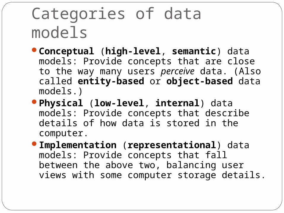
Categories of data modelsConceptual (high-level, semantic) data
models: Provide concepts that are close to the way many users perceive data. (Also called entity-based or object-based data models.)
Physical (low-level, internal) data models: Provide concepts that describe details of how data is stored in the computer.
Implementation (representational) data models: Provide concepts that fall between the above two, balancing user views with some computer storage details.
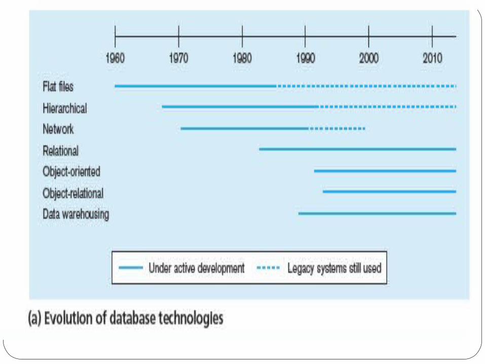


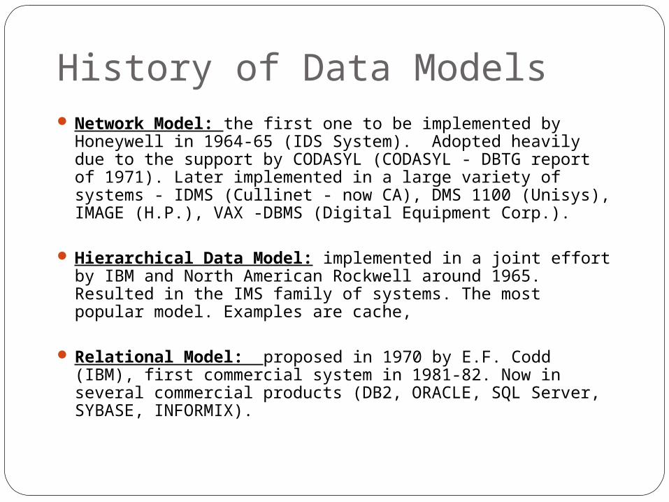
History of Data Models Network Model: the first one to be implemented by
Honeywell in 1964-65 (IDS System). Adopted heavily due to the support by CODASYL (CODASYL - DBTG report of 1971). Later implemented in a large variety of systems - IDMS (Cullinet - now CA), DMS 1100 (Unisys), IMAGE (H.P.), VAX -DBMS (Digital Equipment Corp.).
Hierarchical Data Model: implemented in a joint effort by IBM and North American Rockwell around 1965. Resulted in the IMS family of systems. The most popular model. Examples are cache,
Relational Model: proposed in 1970 by E.F. Codd (IBM), first commercial system in 1981-82. Now in several commercial products (DB2, ORACLE, SQL Server, SYBASE, INFORMIX).

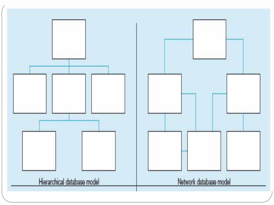
Hierarchical ModelWell suited for data which are in some
way related
Hierarchically begin with a strictly defined tree of data nodes
Each node can contain some identifying
data, plus a set of subnodes of a specific child type
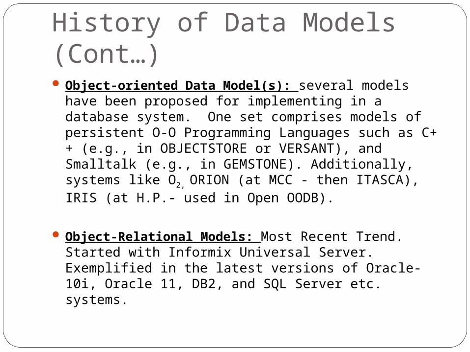
History of Data Models (Cont…) Object-oriented Data Model(s): several models
have been proposed for implementing in a database system. One set comprises models of persistent O-O Programming Languages such as C++ (e.g., in OBJECTSTORE or VERSANT), and Smalltalk (e.g., in GEMSTONE). Additionally, systems like O2, ORION (at MCC - then ITASCA), IRIS (at H.P.- used in Open OODB).
Object-Relational Models: Most Recent Trend. Started with Informix Universal Server. Exemplified in the latest versions of Oracle-10i, Oracle 11, DB2, and SQL Server etc. systems.

Hierarchical Model (Cont…)
Hierarchical Model
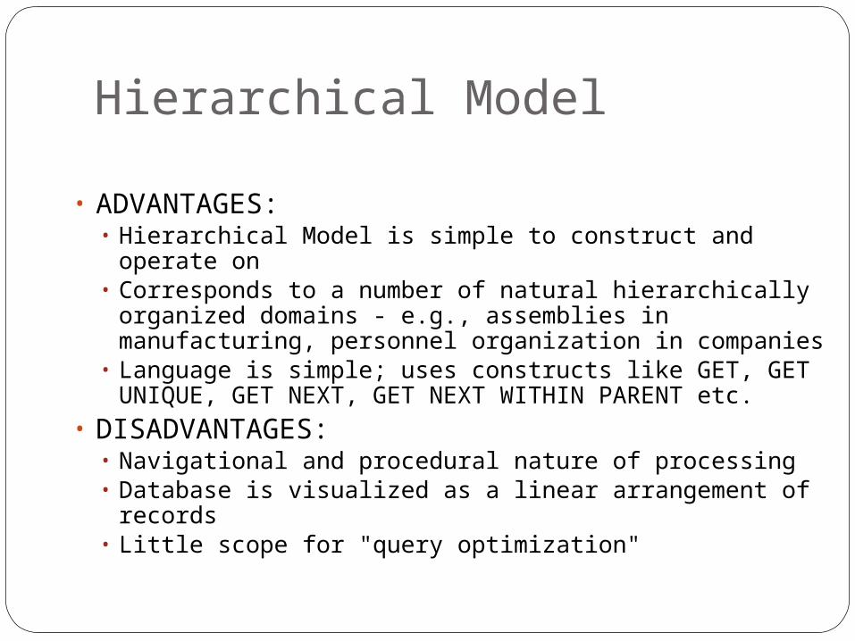
• ADVANTAGES:• Hierarchical Model is simple to construct and operate on• Corresponds to a number of natural hierarchically
organized domains - e.g., assemblies in manufacturing, personnel organization in companies
• Language is simple; uses constructs like GET, GET UNIQUE, GET NEXT, GET NEXT WITHIN PARENT etc.
• DISADVANTAGES:• Navigational and procedural nature of processing• Database is visualized as a linear arrangement of records• Little scope for "query optimization"
Network Model
Supported more complex relationsPhysical file pointers were used to model the
relations between filesRelations had to be decide in advanceMost suitable for large databases with well
defined queries and well-defined applications.
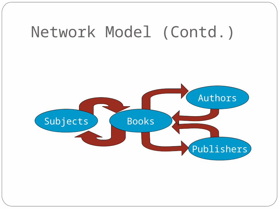
Network Model (Contd.)
Subjects Books
Authors
Publishers
Network Model (Cont…)In other words, according to the network
data model the information within a database is arranged as a collection of record occurrences and a collection of set occurrences.

Example of Network Data Model:

Network Model
ADVANTAGES:• Network Model is able to model complex relationships and
represents semantics of add/delete on the relationships.• Can handle most situations for modeling using record
types and relationship types.• Language is navigational; uses constructs like FIND, FIND
member, FIND owner, FIND NEXT within set, GET etc. Programmers can do optimal navigation through the database.
DISADVANTAGES:• Navigational and procedural nature of processing• Database contains a complex array of pointers that thread
through a set of records. Little scope for automated "query optimization”
Relational Model (1970’s)
E.F. Codd introduced the relational model in 1970
Provides a conceptually simple model for data as relations (typically considered “tables”) with all data visible.
DB2 from IBM is the first DBMS product based on the relational model
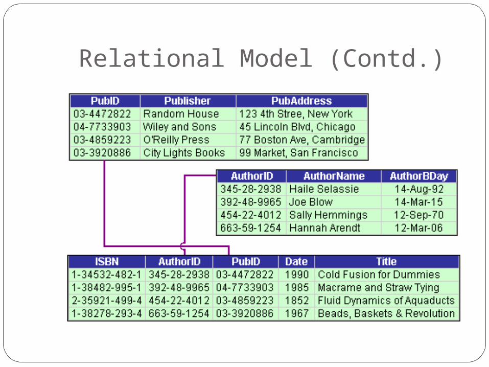
Relational Model (Contd.)
Relational Model (Cont...)Other DBMS based on the relational model
were developed in the late 1980s
Today, DB2, Oracle, and SQL Server are the most prominent commercial DBMS
products based on the relational model
Object Oriented Data Model (1990’s)
Goal of OODBMS is to store object-oriented programming objects in a database without having to transform them into relational
format.Extend the entity-relationship data model
by including encapsulation, methods and object identity

Object-relational modelsExtend the relational data model by
including object orientation and constructs to deal with added data types.
Allow attributes of tuples to have complex types, including non-atomic values such as nested relations.
Preserve relational foundations, in particular the declarative access to data, while extending modeling power.
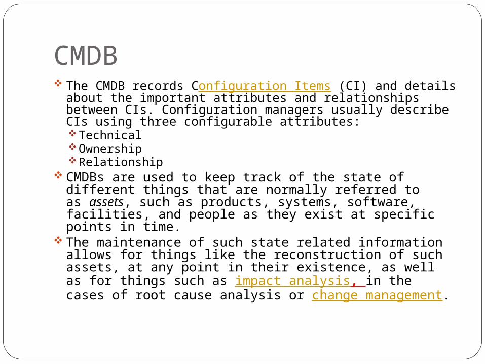
CMDB The CMDB records Configuration Items (CI) and details
about the important attributes and relationships between CIs. Configuration managers usually describe CIs using three configurable attributes:Technical Ownership Relationship
CMDBs are used to keep track of the state of different things that are normally referred to as assets, such as products, systems, software, facilities, and people as they exist at specific points in time.
The maintenance of such state related information allows for things like the reconstruction of such assets, at any point in their existence, as well as for things such as impact analysis, in the cases of root cause analysis or change management.
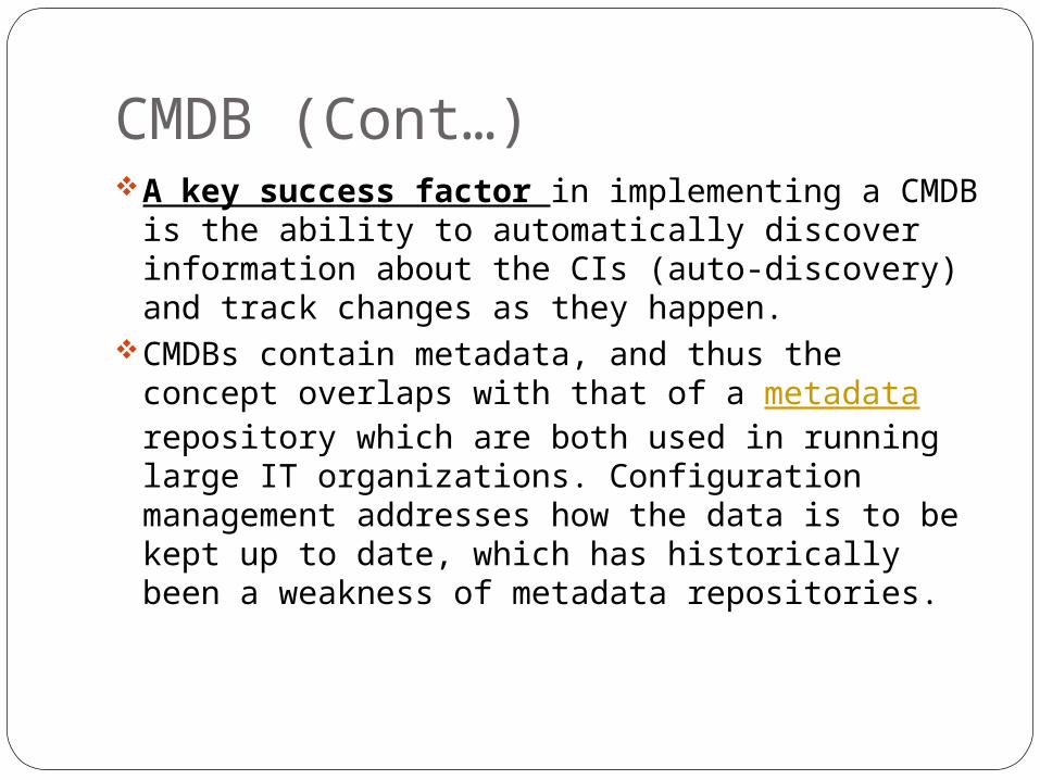
CMDB (Cont…)A key success factor in implementing a
CMDB is the ability to automatically discover information about the CIs (auto-discovery) and track changes as they happen.
CMDBs contain metadata, and thus the concept overlaps with that of a metadata repository which are both used in running large IT organizations. Configuration management addresses how the data is to be kept up to date, which has historically been a weakness of metadata repositories.
Schemas versus Instances
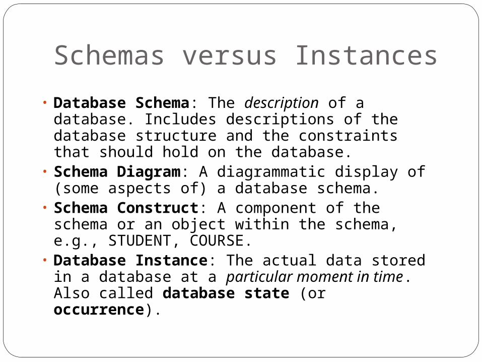
• Database Schema: The description of a database. Includes descriptions of the database structure and the constraints that should hold on the database.
• Schema Diagram: A diagrammatic display of (some aspects of) a database schema.
• Schema Construct: A component of the schema or an object within the schema, e.g., STUDENT, COURSE.
• Database Instance: The actual data stored in a database at a particular moment in time. Also called database state (or occurrence).

Database Schema Vs. Database State
• Database State: Refers to the content of a database at a moment in time.
• Initial Database State: Refers to the database when it is loaded
• Valid State: A state that satisfies the structure and constraints of the database.
• Distinction• The database schema changes very infrequently.
The database state changes every time the database is updated.
• Schema is also called intension, whereas state is called extension.
Now…Consider the following example
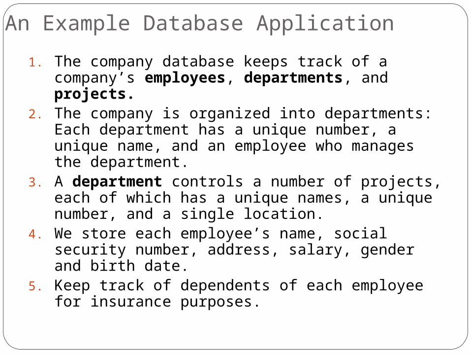
An Example Database Application
1. The company database keeps track of a company’s employees, departments, and projects.
2. The company is organized into departments: Each department has a unique number, a unique name, and an employee who manages the department.
3. A department controls a number of projects, each of which has a unique names, a unique number, and a single location.
4. We store each employee’s name, social security number, address, salary, gender and birth date.
5. Keep track of dependents of each employee for insurance purposes.
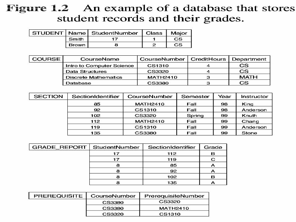

Schema Diagram
Name Studentnumber Class Major
CourseName CourseNumber Department
Student
Course
Data Independence Logical data independence – capacity to
change the conceptual schema without having to change external schemas or application programs.
Maybe changed to expand the database. For example, change constraints, records,
etc. Physical data independence – capacity
to change the internal schema without having to change the conceptual schema.
3. Database Languages and Interfaces
Once design of a database is completed and a DBMS is chosen to implement the database, what is needed:
To specify conceptual and internal schemas for the database and any mappings between the two – Data Definition Language (DDL).
If clear separation is maintained – Storage Definition Language (SDL) is used to specify the internal schema.
For a true three-schema architecture – the View Definition Language (VDL) is needed to specify user views.
Database Languages and Interfaces (Cont.)
A Data Manipulation Language is needed now (DML): retrieval, insertion, deletion, and modification of the data:
A High-level or non-procedural DML – complex database operations.
A Low-level or procedural DML – must be embedded in a general-purpose programming language.
Entity Types, Entity Sets, Attributes, and Keys An Entity is the basic object that the ER
model represents.An Entity may be an object with a physical
existence, i.e. a person, car, houseExamples: Employee, Department, Project

E-R MODEL CONSTRUCTSE-R MODEL CONSTRUCTSEntity instance–person, place, object, event, Entity instance–person, place, object, event,
concept (often corresponds to a row in a table)concept (often corresponds to a row in a table)Entity Type–collection of entity instance (often Entity Type–collection of entity instance (often
corresponds to a table)corresponds to a table)Relationship instance–link between entity Relationship instance–link between entity
instance (corresponds to individual primary key-instance (corresponds to individual primary key-foreign key value match)foreign key value match)
Relationship link between entity types (primary Relationship link between entity types (primary key-foreign key link)key-foreign key link)
37
38
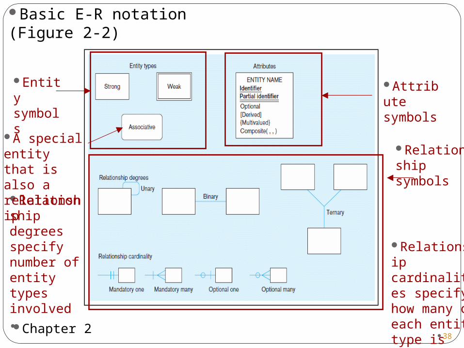
Relationship degrees specify number of entity types involved
Entity symbols
A special entity that is also a relationship
Relationship symbols
Relationship cardinalities specify how many of each entity type is allowed
Attribute symbols
Basic E-R notation (Figure 2-2)
38Chapter 2
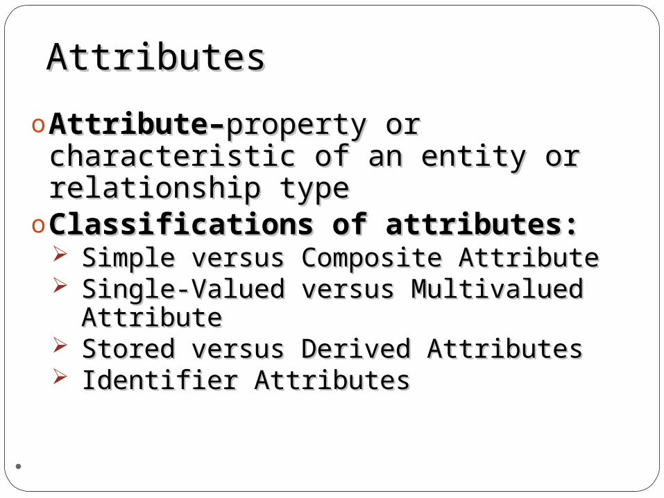
AttributesAttributes
oAttribute–Attribute–property or property or characteristic of an entity or characteristic of an entity or relationship typerelationship type
oClassifications of attributes:Classifications of attributes: Simple versus Composite AttributeSimple versus Composite Attribute Single-Valued versus Multivalued Single-Valued versus Multivalued
AttributeAttribute Stored versus Derived AttributesStored versus Derived Attributes Identifier AttributesIdentifier Attributes
39

Simple vs. Composite Simple vs. Composite AttributesAttributes
Composite attributeComposite attribute – An attribute that has – An attribute that has meaningful component parts (attributes)meaningful component parts (attributes)
40
The address is broken into component parts
Figure 2-7 A composite attribute
41
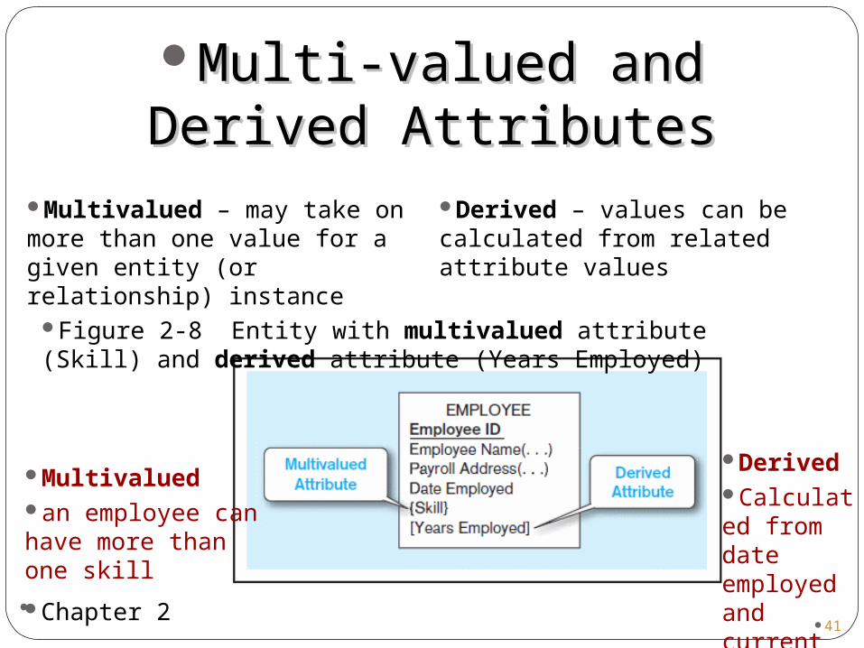
Figure 2-8 Entity with multivalued attribute (Skill) and derived attribute (Years Employed)
Multivaluedan employee can have more than one skill
DerivedCalculated from date employed and current date
Multi-valued and Derived Multi-valued and Derived AttributesAttributes
Multivalued – may take on more than one value for a given entity (or relationship) instance
Derived – values can be calculated from related attribute values
41Chapter 2
Identifiers (Keys)Identifiers (Keys)
o Identifier (Key)–Identifier (Key)–an attribute (or an attribute (or combination of attributes) that combination of attributes) that uniquely identifies individual uniquely identifies individual instances of an entity typeinstances of an entity type
oSimple versus Composite Simple versus Composite IdentifierIdentifier
42
43
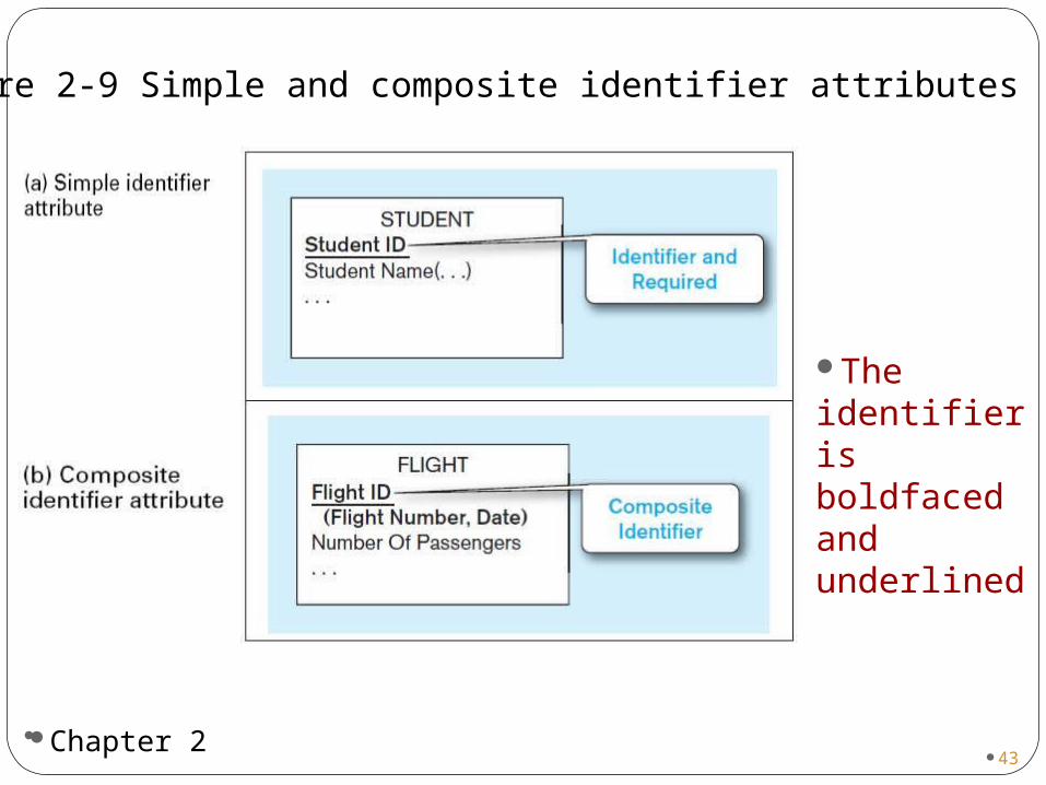
Figure 2-9 Simple and composite identifier attributes
The identifier is boldfaced and underlined
43Chapter 2
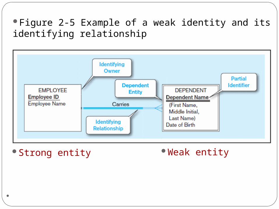
Strong vs. Weak Entities, andStrong vs. Weak Entities, andIdentifying RelationshipsIdentifying Relationships
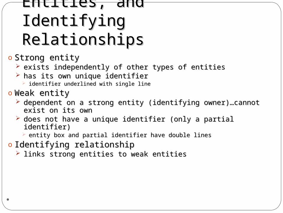
o Strong entity Strong entity exists independently of other types of entitiesexists independently of other types of entities has its own unique identifierhas its own unique identifier
identifier underlined with single lineidentifier underlined with single line
o Weak entityWeak entity dependent on a strong entity (identifying owner)…cannot dependent on a strong entity (identifying owner)…cannot
exist on its ownexist on its own does not have a unique identifier (only a partial identifier)does not have a unique identifier (only a partial identifier)
entity box and partial identifier have double linesentity box and partial identifier have double lines
o Identifying relationshipIdentifying relationship links strong entities to weak entitieslinks strong entities to weak entities
44
45
Strong entity Weak entity
Figure 2-5 Example of a weak identity and its identifying relationship
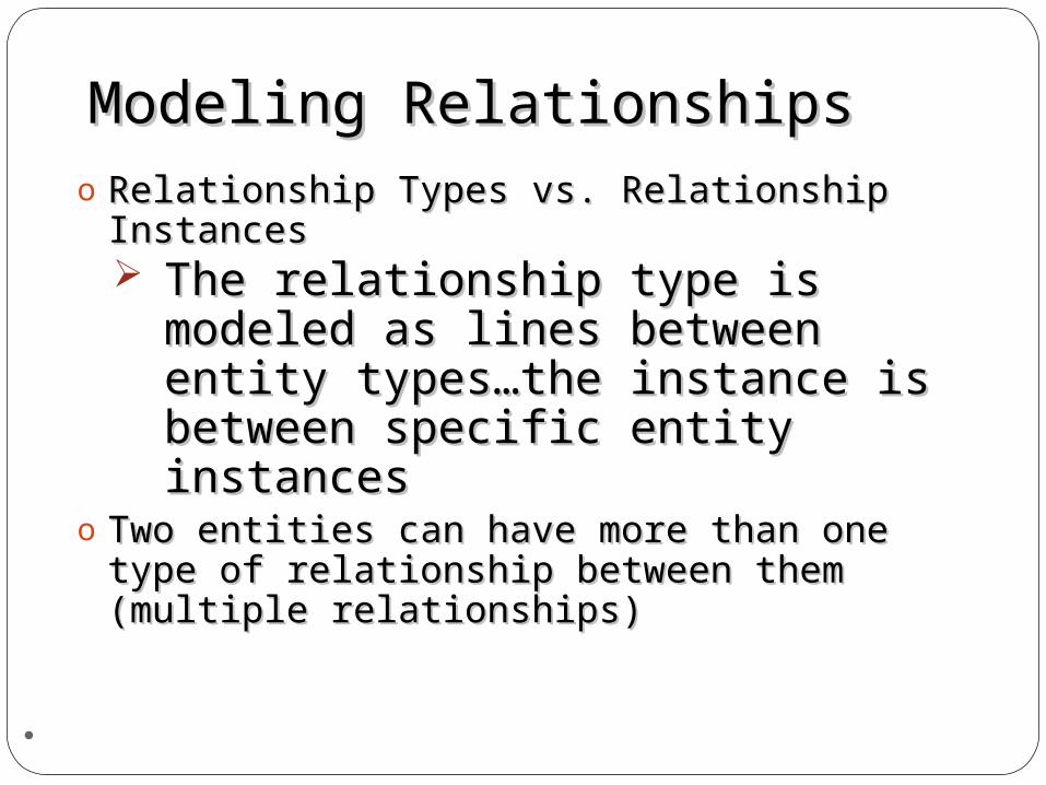
Modeling RelationshipsModeling Relationshipso Relationship Types vs. Relationship Relationship Types vs. Relationship
InstancesInstances The relationship type is modeled The relationship type is modeled
as lines between entity types…as lines between entity types…the instance is between specific the instance is between specific entity instancesentity instances
o Two entities can have more than one type Two entities can have more than one type of relationship between them (multiple of relationship between them (multiple relationships)relationships)
46
47
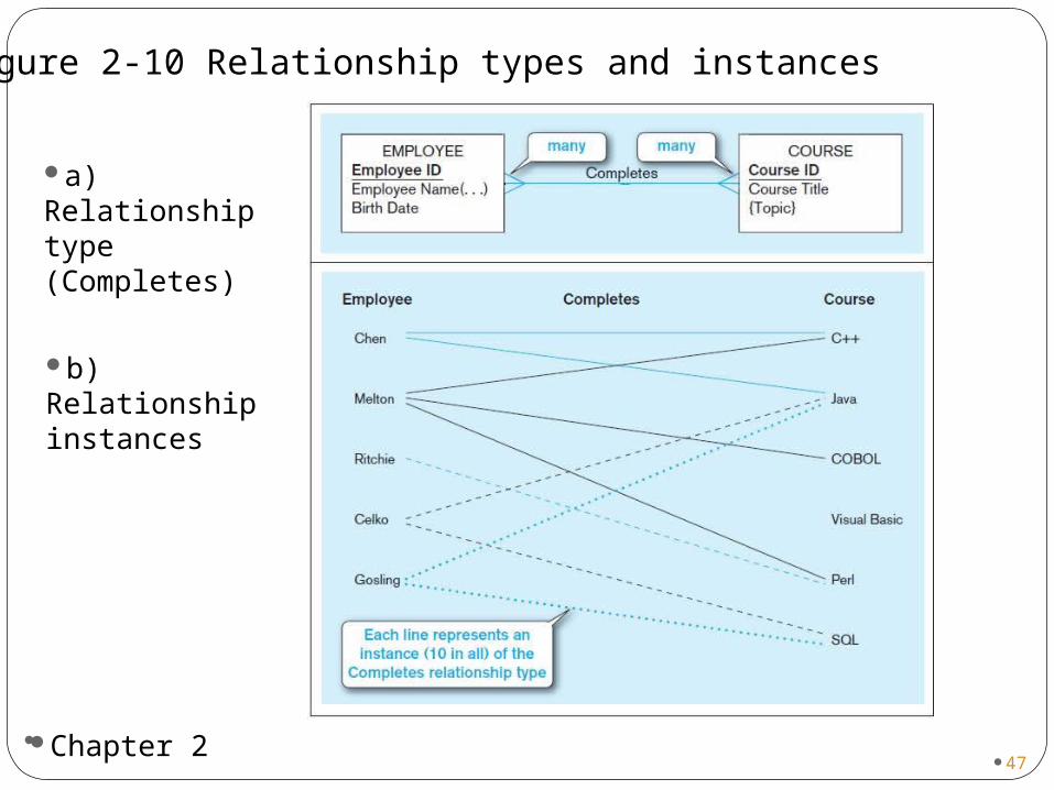
Figure 2-10 Relationship types and instances
a) Relationship type (Completes)
b) Relationship instances
47Chapter 2
Degree of RelationshipsDegree of Relationships
Degree of a relationship Degree of a relationship is the number of entity is the number of entity types that participate in ittypes that participate in it Unary RelationshipUnary Relationship Binary RelationshipBinary Relationship Ternary RelationshipTernary Relationship
48
49
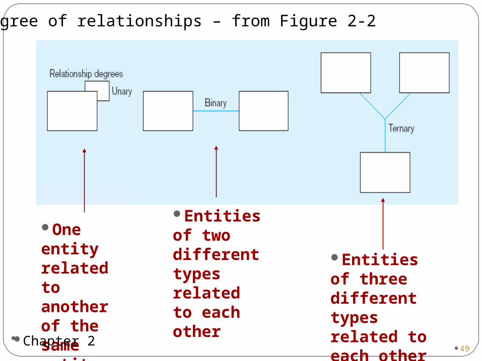
Degree of relationships – from Figure 2-2
Entities of two different types related to each other
Entities of three different types related to each other
One entity related to another of the same entity type
49Chapter 2

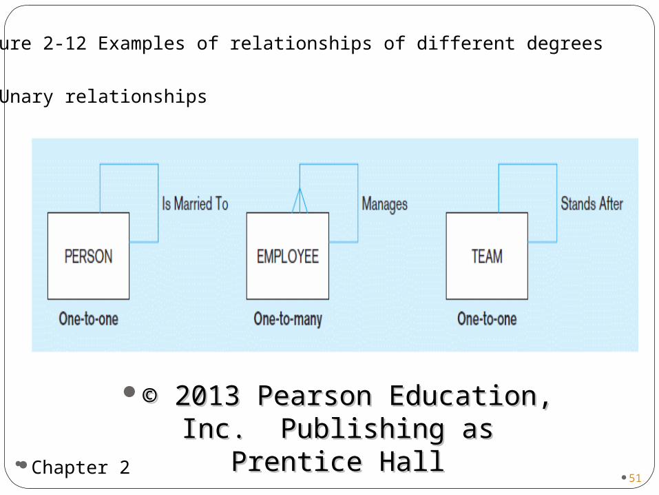
Cardinality of RelationshipsCardinality of RelationshipsOne-to-One: One-to-One: Each entity instance in the Each entity instance in the
relationship will have exactly one related relationship will have exactly one related entity instanceentity instance
One-to-Many:One-to-Many: An entity instance on one An entity instance on one side of the relationship can have many side of the relationship can have many related entity instances, but an entity related entity instances, but an entity instance on the other side will have a instance on the other side will have a maximum of one related entity instance.maximum of one related entity instance.
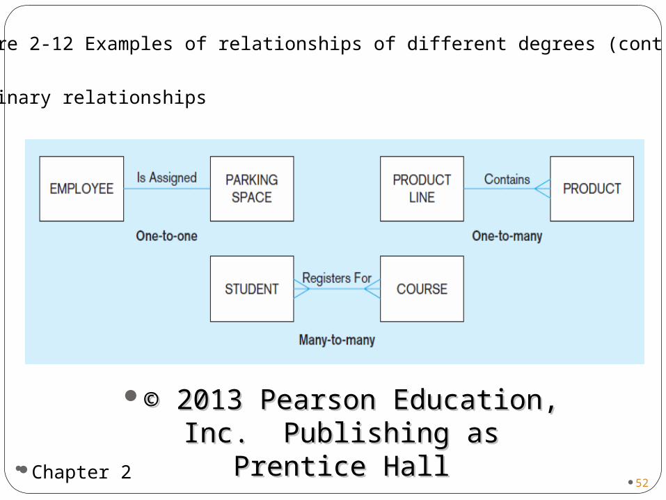
Many-to-Many:Many-to-Many: An entity instance on An entity instance on either side of the relationship can have either side of the relationship can have many related entity instances on the other many related entity instances on the other sideside
50
51
Figure 2-12 Examples of relationships of different degrees
a) Unary relationships
51Chapter 2
© 2013 Pearson Education, Inc. © 2013 Pearson Education, Inc. Publishing as Prentice Hall Publishing as Prentice Hall
52
Figure 2-12 Examples of relationships of different degrees (cont.)
b) Binary relationships
52Chapter 2
© 2013 Pearson Education, Inc. © 2013 Pearson Education, Inc. Publishing as Prentice Hall Publishing as Prentice Hall
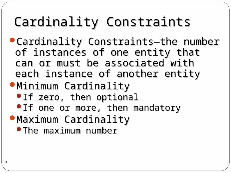
Cardinality ConstraintsCardinality ConstraintsCardinality Constraints—the number of Cardinality Constraints—the number of
instances of one entity that can or instances of one entity that can or must be associated with each instance must be associated with each instance of another entityof another entity
Minimum CardinalityMinimum CardinalityIf zero, then optionalIf zero, then optionalIf one or more, then mandatoryIf one or more, then mandatory
Maximum CardinalityMaximum CardinalityThe maximum numberThe maximum number
53
54
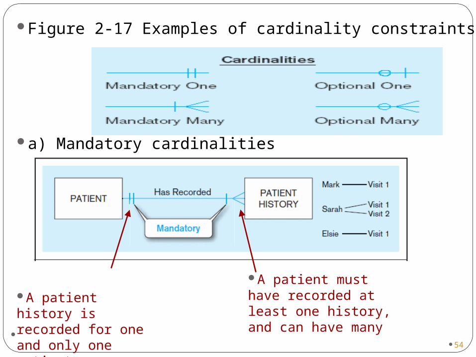
Figure 2-17 Examples of cardinality constraints
a) Mandatory cardinalities
A patient must have recorded at least one history, and can have many
A patient history is recorded for one and only one patient
54
55
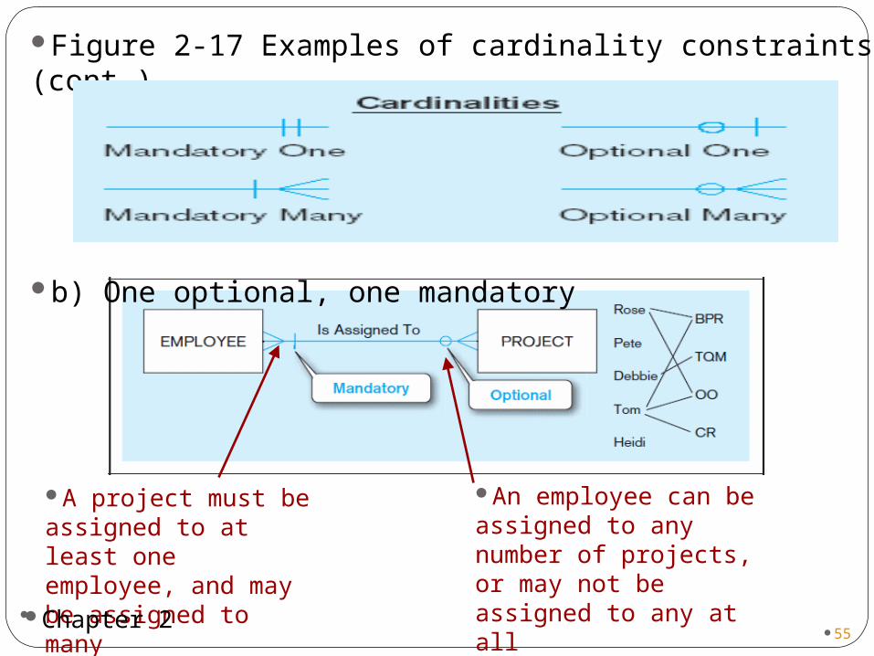
Figure 2-17 Examples of cardinality constraints (cont.)
b) One optional, one mandatory
An employee can be assigned to any number of projects, or may not be assigned to any at all
A project must be assigned to at least one employee, and may be assigned to many
55Chapter 2
56
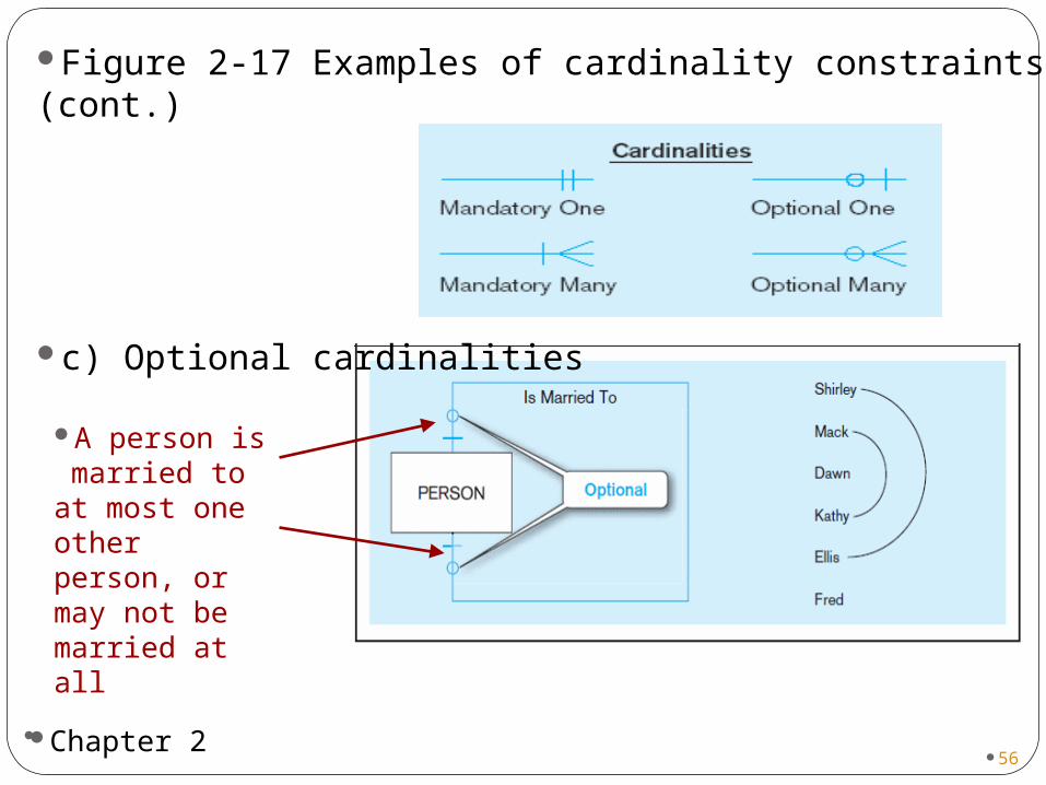
Figure 2-17 Examples of cardinality constraints (cont.)
c) Optional cardinalities
A person is married to at most one other person, or may not be married at all
56Chapter 2
Associative EntitiesAssociative Entities
An entity–has attributesAn entity–has attributesA relationship–links A relationship–links entities togetherentities together
57
58
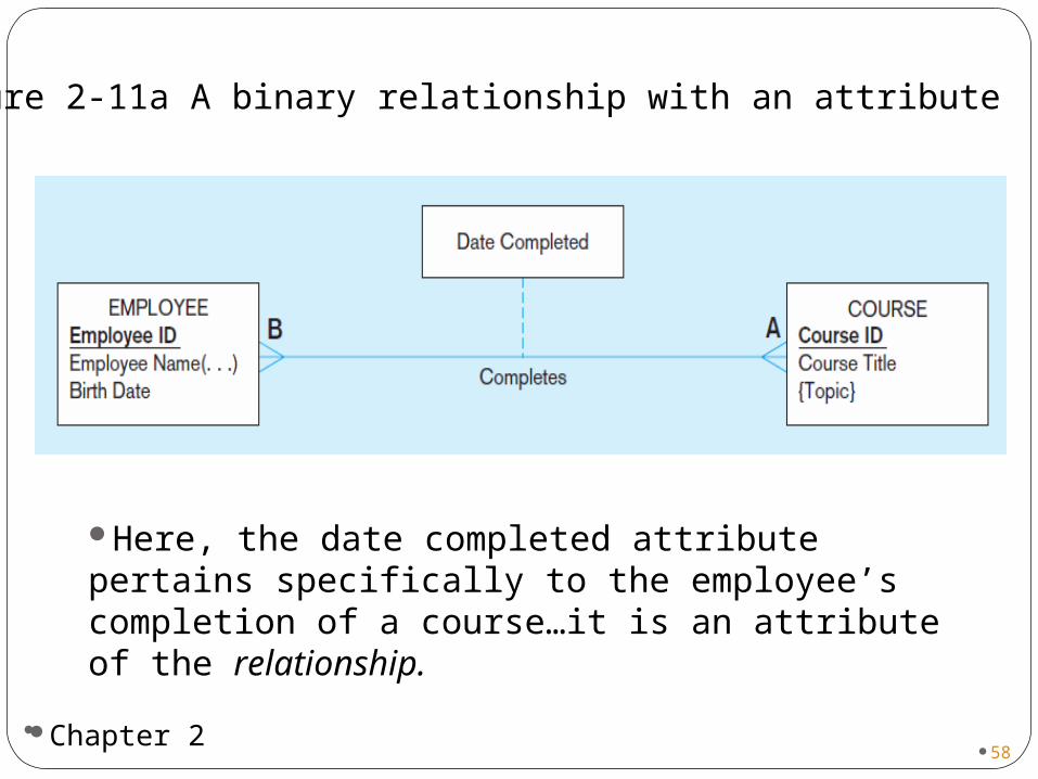
Figure 2-11a A binary relationship with an attribute
Here, the date completed attribute pertains specifically to the employee’s completion of a course…it is an attribute of the relationship.
58Chapter 2

59
Figure 2-11b An associative entity (CERTIFICATE)
Associative entity is like a relationship with an attribute, but it is also considered to be an entity in its own right.
Note that the many-to-many cardinality between entities in Figure 2-11a has been replaced by two one-to-many relationships with the associative entity.
59Chapter 2
60
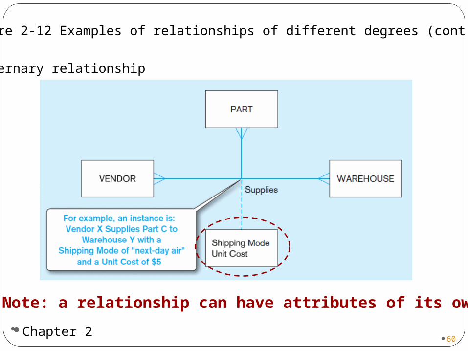
Figure 2-12 Examples of relationships of different degrees (cont.)
c) Ternary relationship
Note: a relationship can have attributes of its own
60Chapter 2
61
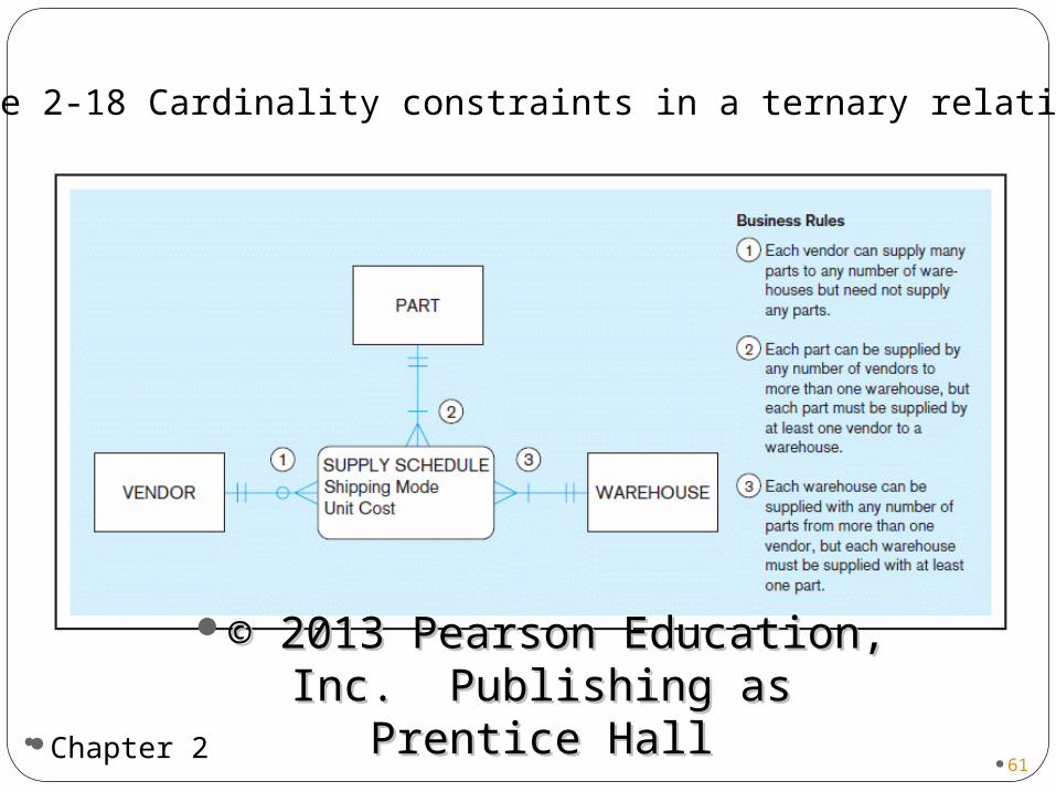
Figure 2-18 Cardinality constraints in a ternary relationship
61Chapter 2
© 2013 Pearson Education, Inc. © 2013 Pearson Education, Inc. Publishing as Prentice Hall Publishing as Prentice Hall
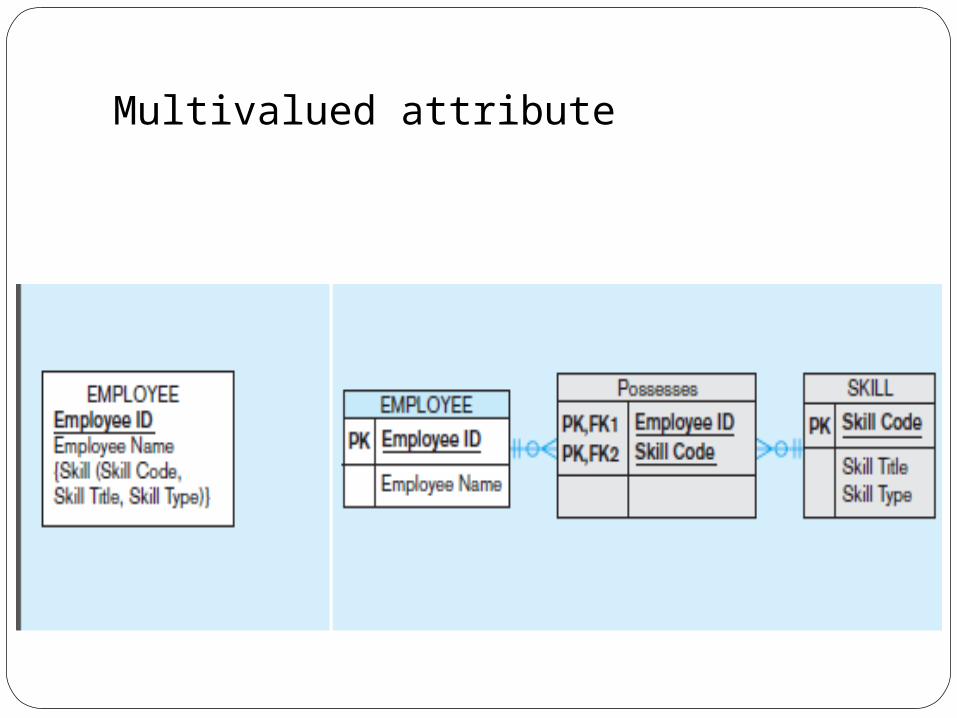
Multivalued attribute
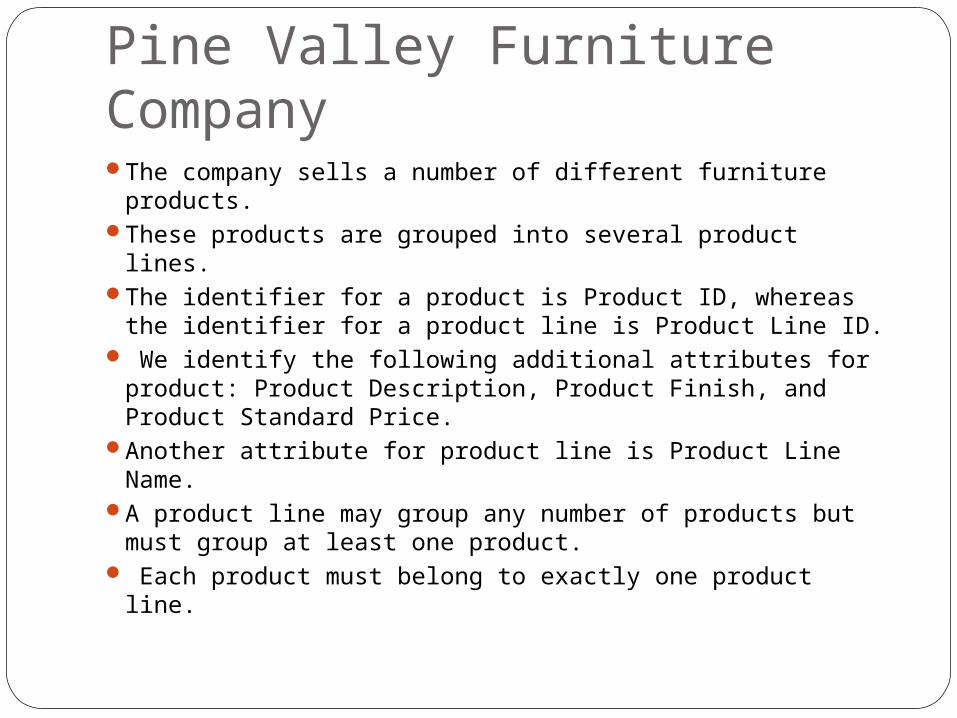
Pine Valley Furniture Company The company sells a number of different furniture
products. These products are grouped into several product lines. The identifier for a product is Product ID, whereas the
identifier for a product line is Product Line ID. We identify the following additional attributes for
product: Product Description, Product Finish, and Product Standard Price.
Another attribute for product line is Product Line Name.
A product line may group any number of products but must group at least one product.
Each product must belong to exactly one product line.
6464
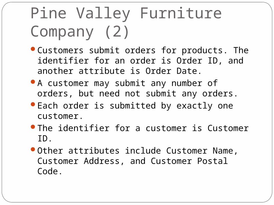
Pine Valley Furniture Company (2)Customers submit orders for products. The
identifier for an order is Order ID, and another attribute is Order Date.
A customer may submit any number of orders, but need not submit any orders.
Each order is submitted by exactly one customer.
The identifier for a customer is Customer ID. Other attributes include Customer Name,
Customer Address, and Customer Postal Code.

6666
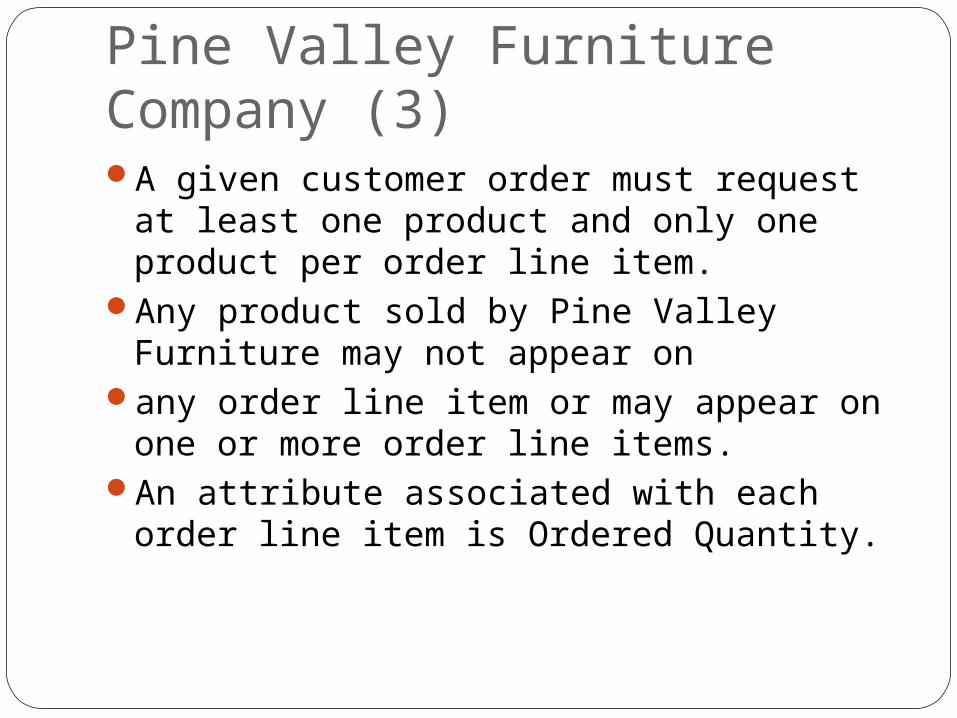
Pine Valley Furniture Company (3)A given customer order must request at
least one product and only one product per order line item.
Any product sold by Pine Valley Furniture may not appear on
any order line item or may appear on one or more order line items.
An attribute associated with each order line item is Ordered Quantity.
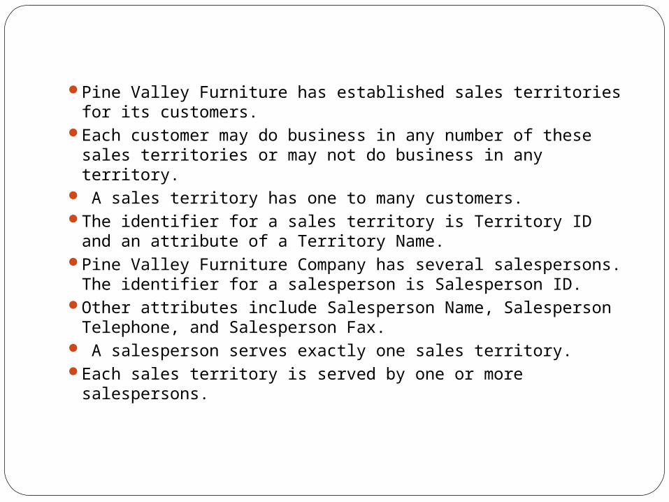
Pine Valley Furniture has established sales territories for its customers.
Each customer may do business in any number of these sales territories or may not do business in any territory.
A sales territory has one to many customers. The identifier for a sales territory is Territory ID and an
attribute of a Territory Name.Pine Valley Furniture Company has several salespersons.
The identifier for a salesperson is Salesperson ID. Other attributes include Salesperson Name, Salesperson
Telephone, and Salesperson Fax. A salesperson serves exactly one sales territory. Each sales territory is served by one or more
salespersons.

Free software ER diagramming tools that can interpret and generate ER models and SQL and do database analysis are MySQL Workbench (formerly DBDesigner), Open ModelSphere (open-source). (www.modelsphere.org) A freeware ER tool that can generate database and application layer code (webservices) is the RISE Editor. SQL Power Architect while proprietary also has a free community edition.
ER Diagramming Tools

How do we start an ERD? 1. Define Entities: these are usually nouns
used in descriptions of the system, in the discussion of business rules, or in documentation;
2. Define Relationships: these are usually verbs used in descriptions of the system or in discussion of the business rules
3. Add attributes to the relations; these are determined by the queries,and may also suggest new entities, e.g. grade; or they may suggest the need for keys or identifiers.
4. Add cardinality to the relations Many-to-Many must be resolved to
two one-to-manys with an additional entity
Usually automatically happens Sometimes involves introduction of a
link entity (which will be all foreign key) Examples: Patient-Drug
Design Techniques1. Avoid redundancy.2. Limit the use of weak entity sets.3. Don’t use an entity set when an attribute
will do.