full-scale tunnel and shaft seals: tunnel sealing experiment … · full-scale tunnel and shaft...
TRANSCRIPT
Full-Scale Tunnel and Shaft Seals: Tunnel Sealing Experiment (TSX)
and Enhanced Sealing Project (ESP)
D.A.Dixon1, D.Priyanto2, P.Korkeakoski3, R.Farhoud4, K.Birch5, A. Man1
1 Golder Associates Ltd., 2 Canadian Nuclear Laboratories,
3 Posiva Oy, 4 Andra, 5 NWMO.
DOPAS – Full Scale Demonstration of Plugs and Seals 2016 Workshop, 24-27 May 2016, Turku Finland.

Background
May 25, 2016 2
ESP Plugs
AECL, (now Canadian Nuclear Laboratories (CNL)) operated an Underground Research Laboratory from 1983 – 2003 with final closure occurring in 2014.
Two of the many demonstrations/experiments were: Tunnel Sealing Experiment (TSX) Enhanced Sealing Project (ESP)
The TSX and ESP examined the behaviour of full-scale bentonite, concrete and combined clay-concrete plugs for tunnels and shafts.
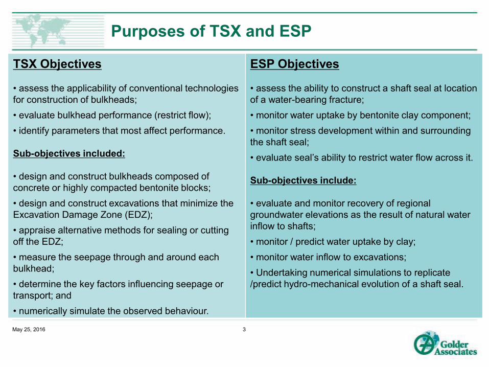
Purposes of TSX and ESP
May 25, 2016 3
TSX Objectives • assess the applicability of conventional technologies for construction of bulkheads; • evaluate bulkhead performance (restrict flow); • identify parameters that most affect performance. Sub-objectives included: • design and construct bulkheads composed of concrete or highly compacted bentonite blocks; • design and construct excavations that minimize the Excavation Damage Zone (EDZ); • appraise alternative methods for sealing or cutting off the EDZ; • measure the seepage through and around each bulkhead; • determine the key factors influencing seepage or transport; and • numerically simulate the observed behaviour.
ESP Objectives • assess the ability to construct a shaft seal at location of a water-bearing fracture; • monitor water uptake by bentonite clay component; • monitor stress development within and surrounding the shaft seal; • evaluate seal’s ability to restrict water flow across it. Sub-objectives include: • evaluate and monitor recovery of regional groundwater elevations as the result of natural water inflow to shafts; • monitor / predict water uptake by clay; • monitor water inflow to excavations; • Undertaking numerical simulations to replicate /predict hydro-mechanical evolution of a shaft seal.

THE TUNNEL SEALING EXPERIMENT
(TSX)
May 25, 2016 4

Tunnel Sealing Experiment (TSX): 1997-2005
Construction: Located at 420 Level of URL in a 3.5 x 4.4m
oval tunnel. >8000 precompacted blocks of 70%
bentonite : 30% sand, Spraying clay on rough rock surfaces, Volume of Clay (67 m3), Mass pour of 76 m3 of Low-Heat, Low-
Shrinkage, High-Performance Concrete 563 Instruments (928 sensors) Water-filled chamber pressurized to 4.2
MPa (~420m head) and heated to 85C while monitoring plugs & rock.
Water collection system allowed seepage paths and quantities to be identified

Rock bolt
Steel shellrestraint
Sandfiller
Clay bulkhead
Rock bolts
ReinforcedConcrete
Bearing Ring
Stainless steel plate
Drain linesTo CollectSeepage
Geotextile to Capture Seepage
Tunnel fill
Shotclay Layer
Backfill Wall
Clay Bulkhead Design and Construction

Monitoring Tools
928 sensors installed.
Monitoring of: Temperature, Water uptake by clay, Bulkhead displacement, internal strain and gross movement Porewater pressure, Total pressure within bulkhead and at contact with rock Localized seepage, Micro seismic and Acoustic emission to track rock damage. Seepage path via tracers.
Detailed results can be found in Project Final Report (Martino et al. 2008. Project Report: The Tunnel Sealing Experiment: 10 Year Summary Report, AECL, URL-121550-REPT-001, Chalk River)
May 25, 2016 7

TSX Monitoring Results
May 25, 2016
8
Clay Bulkhead: • Early-stage channeled flow along clay block interfaces, a filtering / restraint structure is needed, • Clay bulkhead is self sealing, • Keying of rock effectively cut off EDZ, • Seepage ~1.5 cc/min (along clay-rock Interface) at 4.2 MPa. Concrete Bulkhead: • Grouting of rock-concrete interface is necessary, and limits local seepage, • Un-reinforced structure was mechanically stable, • Seepage decreased with time, as result of combined effects of fines entering pathway and thermal expansion of rock and concrete, • Seepage past concrete decreased to ~ 2 cc/min.

Key Observations from TSX
Concrete and mechanically-supported bentonite tunnel seals can provide effective barriers to water seepage.
Clay seal is not discernably affected by temperature increase. Concrete plugs need to have ability to be post-construction grouted. Seepage past concrete is affected by pressure gradient and also
temperature, increasing with gradient and decreasing with temperature. Seepage past concrete decreased with time (clogging of seepage paths
by fines). Concrete plug behaviour once temperature decrease occurs is not
established and cooling may result in increased seepage via rock-concrete interface.
A composite structure incorporating both concrete and clay components should result in an effective and stable seal.
May 25, 2016 9

Results of Numerical Modelling Exercises: TSX
The TSX was numerical modelled to try to reproduce observed behaviour, it was concluded that numerical models are
valuable general design tools but have limitations:
The complexity of the TSX’s geometry (multiple components, interfaces, materials), made numerical simulation problematic.
Model-generated behavioural patterns were generally consistent with field measurements, but commonly differed in magnitudes.
Entirely appropriate T-H-M formulations and relationships can be used but capture of field “reality” may be difficult,
Unanticipated, random or unidentified FEPs (e.g. localized leakage paths) affect field performance, models many not capture seepage “reality”.
With improved experience in numerical modelling and ability to recognize the most important parameters, models have the potential to aid in developing tools that can be used to assist in assessing system performance.
May 25, 2016 10

THE ENHANCED SEALING EXPERIMENT
(ESP)
May 25, 2016 11

Enhanced Sealing Project (ESP): 2009 - Ongoing
Decommissioning of URL was completed in 2010 but ESP is continuing to monitor a full-scale shaft seal. 100 sensors installed in 4.8m x 6m main shaft plug Long term monitoring sensors run ~300 m vertically to data collection terminals

ESP: From a fully-serviced to an unserviced installation
13
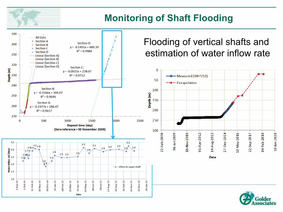
Monitoring of Shaft Flooding
May 25, 2016 14
Flooding of vertical shafts and estimation of water inflow rate
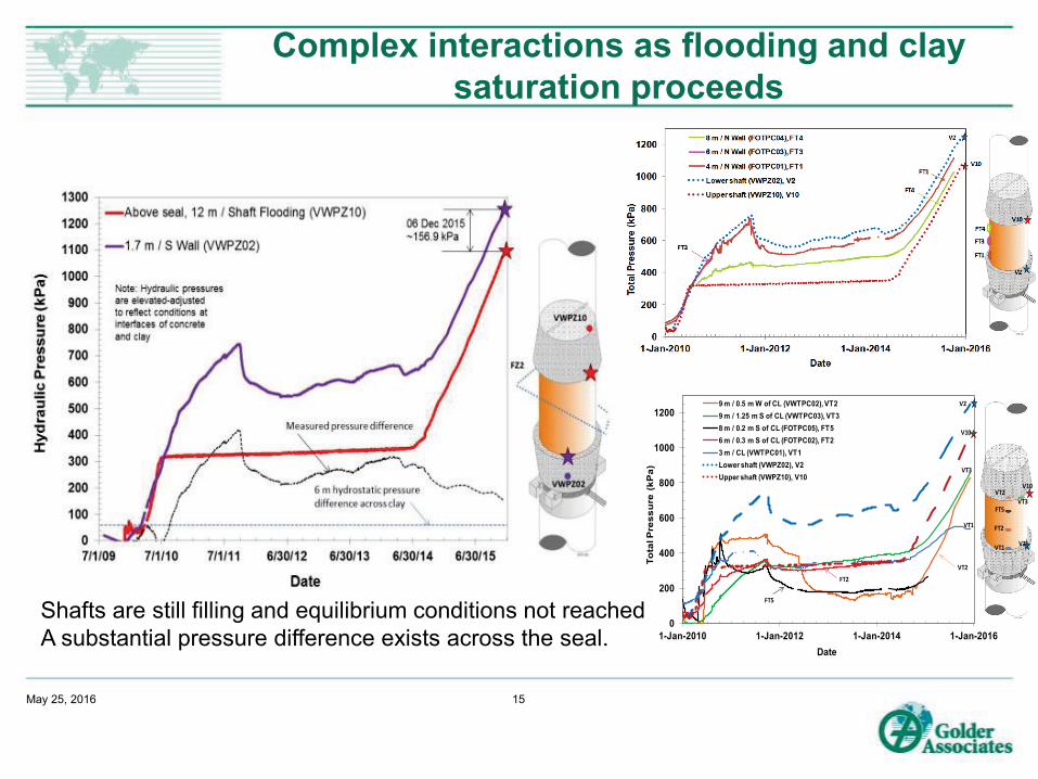
Complex interactions as flooding and clay saturation proceeds
May 25, 2016 15
0
200
400
600
800
1000
1200
1-Jan-2010 1-Jan-2012 1-Jan-2014 1-Jan-2016To
tal P
ress
ure
(kP
a)Date
9 m / 0.5 m W of CL (VWTPC02), VT29 m / 1.25 m S of CL (VWTPC03), VT38 m / 0.2 m S of CL (FOTPC05), FT56 m / 0.3 m S of CL (FOTPC02), FT23 m / CL (VWTPC01), VT1Lower shaft (VWPZ02), V2Upper shaft (VWPZ10), V10
VT2
VT2
VT3
VT3
FT5
FT5
FT2
FT2
VT1
VT1
V2
V10
V10
V2
Shafts are still filling and equilibrium conditions not reached A substantial pressure difference exists across the seal.
Water uptake by bentonite clay seal
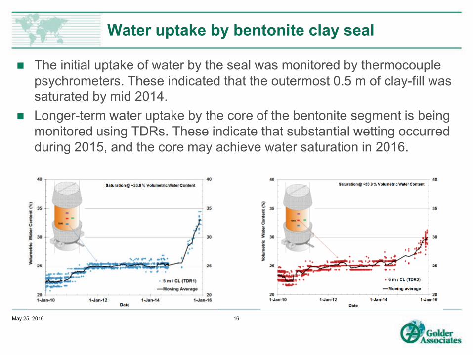
The initial uptake of water by the seal was monitored by thermocouple psychrometers. These indicated that the outermost 0.5 m of clay-fill was saturated by mid 2014.
Longer-term water uptake by the core of the bentonite segment is being monitored using TDRs. These indicate that substantial wetting occurred during 2015, and the core may achieve water saturation in 2016.
May 25, 2016 16
Numerical Modelling Exercises: ESP
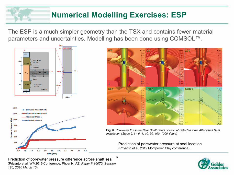
The ESP is a much simpler geometry than the TSX and contains fewer material parameters and uncertainties. Modelling has been done using COMSOL™.
Prediction of porewater pressure difference across shaft seal (Priyanto et al. WM2016 Conference, Phoenix, AZ, Paper # 16070, Session 126, 2016 March 10)
17
Fig. 6. Porewater Pressure Near Shaft Seal Location at Selected Time After Shaft Seal Installation (Stage 2, t = 0, 1, 10, 50, 100, 1000 Years)
0 Year
Prediction of porewater pressure at seal location (Priyanto et al. 2012 Montpellier Clay conference).

SUMMARY
May 25, 2016 18
The ability to construct full-scale tunnel plugs and shaft seals using conventional technology has been demonstrated.
Monitoring underground installations from a considerable distance is challenging and can prove very expensive to accomplish.
The effectiveness of concrete and bentonite-based sealing components were demonstrated in isolation in the TSX and in combination in the ESP.
The composite concrete – bentonite seal in the ESP is resisting water movement between the upper and lower shaft.
Monitoring of the ESP will continue to the end of 2016, at which time it will be decided if further monitoring will occur. When monitoring ends, abandonment will be accomplished by removing sensor cables and the protective enclosure.
---------------------------------------------------------------------------------------------------------------------------------------------------------------------------------------------------------
Numerical modelling of installation performance can prove difficult, in part due to the difficulty in establishing all the FEPs affecting the installation
May 25, 2016 19

QUESTIONS ?
May 25, 2016 20