full paper (pdf) -
TRANSCRIPT

.
(3THE SOCIEN OF NAVALARCHITECTSAND MARINE ENGINEERS,,@,,,.,$One WorldTradeCenter,Suite1369,New York,N.Y.10048
#
0:0
“+~ Paw,.t.bepresentedd ExtremeLoadsResponseSy!np.asi.m
s : Arlin@a”,VA,October19–26,1981?4 ●.s%
#*“,.,***
Structural Failure of a Small Cargo VesselAmong Rough SeasY. Yamamoto and H. Ohtsubo, University of Tokyo, Tokyo, Japan
Y. Takeda, lshikawajima-Harima Heavy Industries Co, Ltd., Tokyo, Japan
T. Fukasawa, University of Tsukuba, Ibaragi, Japan
ABSTRACT
A small cargo vessel Or 48 m suf-fered from serious damages among roughseas, and its main hull was bent at S.S.? by a hogging moment. The ship underconsideration was in ballast condition,and was carrying a large amount of bal-last water in the fore peak tank. Inthis paper, the analysis based on hydro-elasticity shows that this damage iscaused by a hogging moment due to bottomslamming, although in the case of con-ventional 8hips slamming causes a largesagging moment in the mid-part. Elasticresponses are calculated step-by-stepfor the ship idealized as a Timoshenkobeam taking account of slamming impactforces determined with respect to instan-taneous configurations. It is shownthat slamming responses give hoggingmoment sufficient for the damage in anunlucky condition of waxes correspondingto the sea state reverted. Moreover.the collapsing stre~gth of the ship isestimated with the aid of structural ex-periments.
INTRODUCTION
A small cargo ship in ballast con-dition suffered from serious damazesamong rough seas; its fore-body s~appedoff at S.S. 7, forming a plastic hingthere instantaneously. It is reportedthat she failed after Dassin’z throu$zha pair of wave crests Bf 4 meters i;height in seas of state 6. The damageswere evidently caused by high hoggingmoment. Although in a conventional shipslamming causes large sagging moment inthe middle part of the ship?s hull [1,2]*, the report suggests that slammingmay play an inqm~tant role for this prob-lem. In the case of a small cargo shipin ballast condition, the ballast wateris concentrated in the fore- and aft-peak tanks because of her single-bottomstructure, and this ca,uses large hoggingmoment in her middle part when in thestill water condition. In general, lit-
● Note: Numbers in brackets denotes ref-erences located on page
tle attention has been paid to the fore-draft, and she may have had a large trimangle. It is a well-known fact that shemay often encounter relatively hi~hwaies. She may frequently su~fer~there-fore, from bottom slamming in the middlepart in actual sea conditions. Thisconsideration can be confirmed by a re-Dort tellin&z that bottom corrugations~ccur due t: slamming preSSUre-OVe I.awide range of mope than one-half of he~length [3] . This fact suggests a pos-sibility of occurrence of hiEh howaingmoment ;ue to slamming in ad~itio~-to -the la~ge still-water bending moment.
In this paper, the authors analyzethe damage of the above-mentioned shinfrom the-viewpoint of slamming. Her ‘behavior in head seas moving into a wavetrain is investigated by idealizing heras an assemblage of the Tlmoshenko beamelements. Hyd~odynamic impact on thebottom is clos,ely related to her instan-taneous wave-hull conf igtn-ations, andtherefore, calculations are performed bythe step-by-step method. Histories ofbending moment are compared with theultimate collapsing moment which hasbeen estimated with the help of struct-ural expez-iments.
THEORY OF SHIP!S BEHAVIOR AMONG WAVES
Most pi-e”ious authors have inves-tigated the longitudinal bending momentIn a ship among wa”e!s by the two-stepapproach; that is, its rigid body motionIs calculated first by the conventionalmethod, and then hull vibration re-sponses are obtained by making use ofthe impact force estimated f~om theship ts Felative “elocity with Fespectto waves [4-8]. In reality, however,the shiD1s motion is influenced bv theslamming impact, and this two-ste~ ap-proach may give unrealistic results.Meyerhoff and Schlachter [9] developeda nonlinear theory of a ship Ts motionamong waves taking account of slammingimpact, and determined the bending mo-ment by the two-step approach.
Yamamoto, Fujino, and Fukasawa de-veloped a nonlinear theory of a shipts
101 +———

behavior among waves, assuming the shipto be an elastic beam. They appliedGalerkints method with the use of thelower harmonics, as has been successfulfor the analysis of large tanker-typeships and container carriers. In thecase of small cargo vessels, however,higher harmonics may become of Importancebecause the large slamming impacts actnear the nodal points of lower “ibyationmodes. For determining dynamic responses,the finite element method can be conven-iently applied, and In the present papeY,it is formulated by idealizing the Shipvahull as a Timoshenko beam.
Fig. 1 Reference systems
The rectangular coordinate system(X, Y, Z) is introduced so that the x,Y-plane lies on the still water surface,and the Z-axis directs upward as shown inFig. 1. Consider a ship advancing witha constant sDeed. U. in the uositive X-dlrectlon. ~ntrkdu~e the mo;ing coordi-nate system (x, y, z) moving with theship so that the x, Y-Plane lies in theX, Y-plane keeping the x-axis parallelto the X-axis. Since the inclination ofthe ship girder is sufficiently small,the x-axis can be rega~ded as the elementaxis. Assume that a wave train tra”elsin the negative X-direction.
Deformations of the shipts hull canbe described by the upward total dis-placement, w, and the shear deflect ion,w, . The eauation of motion of the s,hi~,sh~ll can b: formulated as an eiastic ‘beam taking account of shear deformation,and disregarding the rotary inertia.It is given by
where m, EI, GAw, nb, n~, and fz arethe mass per unit length, the flexuralrigidity, the shear rigidity, the struc-
102
Fig. 2 Deformations of ship girder
tural damping coefficients for bendingand shearing, and the external force,defined at each section of the ship.Here
w-w~=wb
is the flexural deflection.
On the same concept as the conven-tional striD method. the external forcecaused by the momenium change of fluid,fm, is given by
fm=- &MH(~ - Vz)l, (3)
where MH and VZ are the time-varyingsectional added mass for vertical motionand the vertical comDonent of the orbit-al velocity of the i;cident wave suF-face, and
D a a~=at -u%”
(4)
The most significant term in the expres-sion for fm given by (3) is the impactforce
which is in proportion to the square ofthe relative velocity of the ship to thewave surface [10-12] . The damping force,fp, due to wave-making, is in proportionto the relative velocity, and is givenby
fr = - NH(%- Vz), (6)
where N?
is the time-varying sectionalwave-mak ng damping coefficier,t for “er-tical motion.
Consider the Dressure force. f“.From Bernoulli fs equation, the p;es~ure,P, is Eiven in the following form bydisregarding terms of higher order:
—-

p=-p~-og(zo+ w), (7)
where Q, P, g, and z, are the velocitypotential of the incident wave train,the mass density of water, accelerationdue to gravity, and the z-coordinate ofa POint on the hull in the still watercondition (see Fig. 3) . The pI.essuI.eforce is obtained by integrating it overthe instantaneous wetted surface, C, ofthe hull; that is,
fp = ~ (-p)nz d., (8)
where nz is the z-component of the out-ward unit normal vectorsurface in a transverseducing Eq. (7) into Eq.
fp = -pgj_;(zo +
=Pg A.
on the ship,ssection. Intro-(8) leads to
W - <w) dy
(9)
where A and Cw are the effective sec-tional area and the elevation of subsur-face corresponding to the draft or theeffective wave elevatlon gl”en by
~w=+?l, (lo)
z
v A-(a+w-~)h
——
4’Y-=
n
Fi&. 3 Ship section and wave surface
Since the weight per unit lengthof the ship is given by
fg=mg, (11)
the total external force per unit length,fz, is Obtained by summing UP all thecomponents of the force;
fz=fm+fr+fp+fg. (12)
The displacement, w, can convenient-ly be divided Into two parts, the linear
103
or rigid-body-motion mode and the vibra-tion mode;
W=wr+wv.
The rigid-body-motionexpressed by
‘r=z* +(X-
(13)
mode, w=, can be
+)e, (14)
where Zm and @ indicate hea”e andpitch. Actual heave and pitch motionsare accompanied by some “ibration mode.The “ib~ation mode, Wv, is expressed asa sum of the rlexu~al part, WVb, and theshear deflection, wS;
w“=wvb+w8, (15)
where
wv~=wb-wr,
The degrees of freedom corresponding toall the displacements, w, WP, and “$,have th~ee ~edundancies; one is for giv-ing a zero base of the shear deflection,and the other two are for the definitionof the rigid-body-motion mode; therefore,it will be assumed that
Ws =0
W“=o
where PI andnear the nodesvibration made
P2ofin
at PI,
I
I(16)
at PI and P2, J
are convt?nier.tlytakenthe ship ts two-nodestill water [13].
For the sake sf simplicity, it willbe assumed that the structural dampingcan be expressed by the equivalent log-arithmic decrement, 6V, for each vibra-tion mode such that [cf. Ref. 14]
6r=o, (17)
6V = 62(%) or nb = nS = ~ (18) -
In the following example calc”latlons,62 = 0.056 will be used [151.
The numerical procedure for solving(1) and (2) is based on the finite ele-ment analvsis bv discretlzln~ the shi~girder fo> the kinoshenko be~ elemeniat the nodal pointsxN+l - xl . ~, ~See’F:~’ (j = l!...,N+I;4). Assumethat the displacement components, Wvb (=
Wv - WS) and WS, are given by cubic orllnear polynomials i“ each element, res-pectively; they are expressed in termsof the nodal displacements,
(q - ‘SJ ●
‘bj) Orwsj, (J = I,....N+I), were
ebj=r$j-e (19)

I1
0
e.ebj.,
wVl=wVbj+w, W
xl
0 [
Fig. 4 Timoshenko beam idealization
The finite element formulation canbe derived from Hamilton Ts Principle
/
t2[d(T-V)-iSD+6W] dt = O , (20)
tl
[‘rr + M*Fr Mrv + M*PV
1(1
6i-
lMVF + M*VT Mvv + M*VV ~v
[
~*rF
1{1
C*FV ip
+ C*VP c“” + C*VV &
[
~*yr ~*rv
1{1=
%
+ K*vr Kvv + K*VV q“
f*y
1, (26)f*”
where [M*FrC*M*Fv, M*VP M*””], [C*rrC*~*rv> c*vr J, and [K*rr K*r”, K*vr
,,,,]are due To the added water mass.th~’wave-making damping force, and th~buoyant fopce, respectively.
The equation of !notio” given by(26) will be integrated by the directintegration pi-oceduye, taking account ofthe nonlint?a~ effects, and for this pUF_pose, a Newmark beta method w?.th 6 = 1/4Will be adopted from the “iewpolnt ofstability and accuracy. Nonlinearly iesof the present problem arise from theunderwater geometry of the ship and theimuact force due to slaromine: since the
where the kinetic energy, T, the strainformer is self-explanatory, ‘ihe latter
enerzv. V. the dissipation function. D.will be discussed in detail hereafter.
-. ,and the virtual work’ done by extern~l ‘force, 6W, are such that
T =~~’ m(~)zdx , (21
V[W, w.: .*lL ,E1(a’(w-w,o
ax’ ‘2
+ GAW(332] dx , (22)
Let qr and q“ be the totality of thedegrees of freedom corresponding to therigid-body-motion or vibration mode, res-pectively. Then the equation of motionderived from (20) is given in the follow-ing matrix form(see Appendix 1):
[; ~1 l:] + [: C:j {:}
This equation can be rewritten in thefollowing form by expressing the hydro-dynamical forces explicitly, which makenumerical computations stable:
104
For estimating the hydrodynamicimpact force, the time derivative of theadded mass in (5) will be evaluated bythe following formula:
-1+
for bottom impact,aMH .at
(27)aMH a~~ ~ otherwise,
where ~ and At are the instantaneousdraft and a discrete time interval usedfor time integration. Because of itssmallness, the hydrodynamic impact forcecan be disregarded when the ship sectionemerges from water; namely,
{
aM~ ~~ if~_v <o_—at (~-vz) Dt z
‘imp =‘ (28)
o if~-vz20 .
The val:dity of this assumption is con-firmed by the results of the forced os-cillation test shown in Fig. 5 [11]. Al-though they depend upon the encounterfrequency, we, and the mode Of mOti On,the added mass, MH, and the wave-makingdamping coefficient, NH, will be assumedto be given by
MH .~TP jiz for both rigid-body-motion and vibrationmodes, (29)
—-
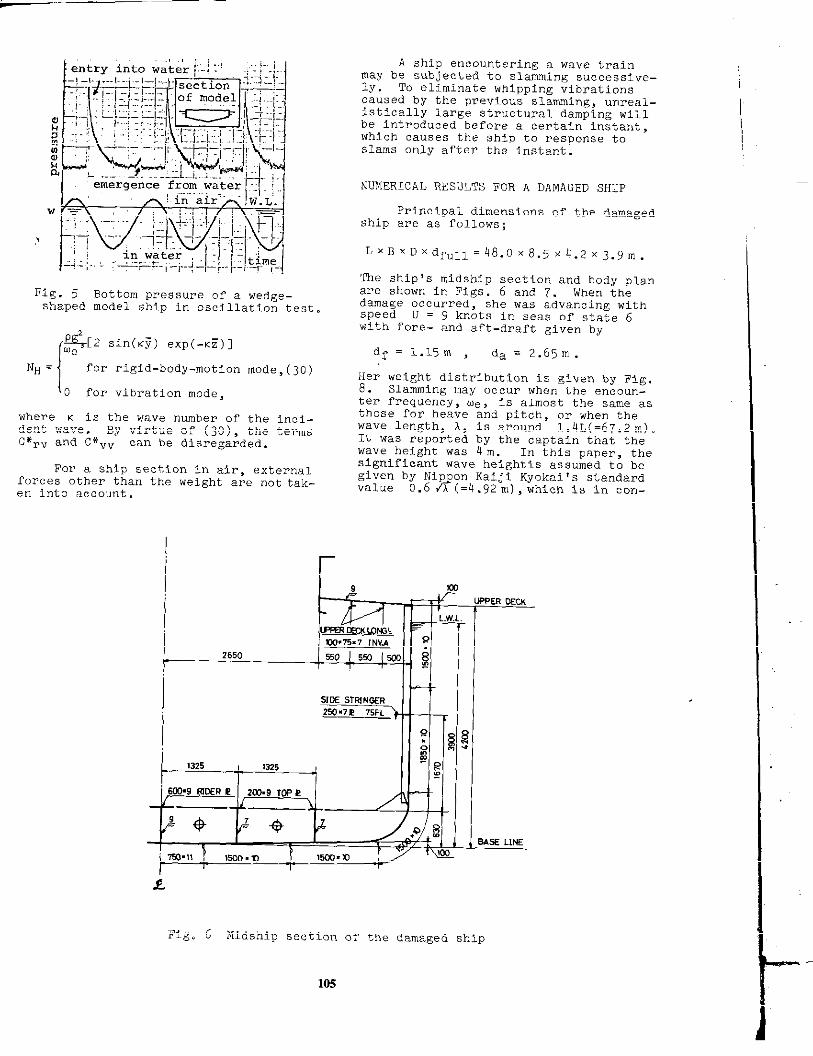
Fig. 5 Bottom pressure of a wedge-shzped model ship in oscillation test.
{
$$[2sin(j) exp(-.i)]
NH . for rigid-body-motion mode, (30)
O for vibration mode,
where K is the wave number of the inci-dent wave. By virtue of (30), the termsC*rv and C*”V can be disregarded.
cur a snip s?forces other thanen into account.
---- -.. ,.. ‘ctlon in air, e.xtei-nalthe weight are not tak-
r
A ship encounte~ing a wave trainmay be subjected to slamming successive-ly . To eliminate whipping vibrationscaused by the previous slamming, unreal-istically large structural damping willbe intFod”ced befope a ce~tain instant,which causes the ship to response toslams only after the instant.
NUMERICAL RESULTS FOR A DAMAGED SHIP
Principal dimensions of the damagedship are as follows;
Lx BxDxdr”ll = 48.0x8.5x ti.2x3.9m.
The shipfs midship section and body planare shown in Figs. 6 and 7. when thedamage occm.red, she was advancing withspeed U = 9 knots in SeaS of State 6with fore- and aft-draft gi”en by
d? = 1.15m da = 2.65m.
Her weight distribution is given by Fig.8. Slamming may occur when the encoun-ter frequency, w, is almost the same 8.sthose for heave and pitch, Or When thewave length, A, is around 1.4L(=67.2111).It WaS Peported by the captain that thewave height was 4 m. In this paper, thesignificant wane heightis assumed to begiven by Nip on Kaiji Kyokai *s standardvalue P0.6 A (=4.92 m), which is in con-
i
Fig. 6 Midship section of the damaged ship
10s

formlty with the captain!s report, be-cause his observed wave height 4m may beless than the actual one in the case ofsmall ships. As can be seen in Fig. i’,the damaged section (S.S. 7) is almostthe same as the midship section. Themoment of inertia of the midship section,I, is &i”en by
I = 606,136 MM2M2,
and it will be assumed that the momentof inertia of each section is in pFopoF -tion to the breadth of the section onload water line. The web area of sec-tion, Aw, is assuned to be constant;
Aw = 8,ooo rm2.
The =ltimate collapsing hogging momentof the damaged section, I!u, is obtainedin Appendix 2, and is given by
% = 41.5 MNm.
Foi-the sake of simplicity, it willbe assumed fik-stthat the ship encoun-ters a regular wave train. Let Hw, w ,and K be the wave height, the frequent y,and the wave number, of the wave train,respectively. Results obtained areshown in Fi’zs. 9 and 10 in which thesame numera~.c encircled indicate an in-stant common to these figu~es. Theyshow that the maximum hogging moment islower than the ultimate collapsing mo.ment, Mu. This situation is caused bythe fact that the slamming impact trav-els forward from near the midship first,and after a certain time interval anoth-er Impact travels aftward from her foreend. A considerable part of the hoggingmoment caused by the former is cancelledby the latter. Calculated bending nm-ment results for the “arious wane heightsare shown in Fig. 11. It is shown thatthe calculated peak hogging moments atS.S. 7 in regular wanes never attain theultimate collapsing moment even in un-realistically high waves; therefore, thedamage could not occur in regular waves.
6n
4rr
‘all
Fig. 7 Body plan
2 OJ --- amyancy-Z~15-~
-1o-
E 5- 1//
\\\
07A.P. Q F. P.
Fig. 8 Weight and buoyancy dis-tributions
M El
=s II “ time@ au
&tIanEm.rq..u — YO..k+hv.JetI-.IIIwfawd
- SlOnnhawa, ,ra”winqbochmrd
Fig. 9 Time history of bending momentat S.S. 7 in regular waves
— inwaves
30, ----Instillwater
Fig. 10
=* 0’
Longitudinal bending momentdistribution
NM
—

Ultimatehoggingmoment50
1 I(estimated)
Fig. 11 Maximum hogging moment vs.wave height
Actual rough seas are not regular,but have a stochastic structure. cor-responding to the spectrum gi”en by Fig.12, the wave is assumed to be given inthe two-term expression for c such that
G = hl CO.3(KiX + tilt)
+ h2 COS[(2K1X +~wlt) + a],(31)
where
KI = 21r/A1> il/’L= 1.4, OJl=@-& ,
2h1=4.92m, 2h2=lo48m.
Here a is defined by the phase angle atthe instant when the ship!s midship sec-tion acorsses the crest line of the long-er wave component of wave height 2 hljust before the occurrence of a slam;a/n = 0.566 has been used as the stand_ard value for the present calculations.
‘t~u)
!IL-n
/’:
/1
PI\
0w
Fig. 12 Wave spectrum for anirregular wave
50,
Fig. 13 Time history of bending momentat S.S. 7 in WaVeS giVen by (31)
Fig. 14 Time history of bending mc,-ment at midship
50
1
— in waves
---- i“ stillW,e,
n
a .&92- ‘- bylinearstriph~ry%= l.wmM = 1.6 n
I
Fig. 15 Longitudinal bending momentdistribution
I
L107

.
m
-m{
Fig. 16 MotIon of ship relative towaves
In thifi sea condition, the ship!s slam-ming impact travels forward from the mid-ship for a sufficiently long time inter-val before a bottom slam occurs in thefore end. The ship 1s bending momentsobtained are shown in Figs. 13-15, Itsconfigurations are shown in Fig. 16,and behaviors of the slams are shown inFig. 17. The points or curves with thesaiienumerals i?ncircled correspond toeach other. Figs.13 and 14 show the timehistory of bending moment at S.S.7 andmidship, and Fig. 15 shows their 10ngl-tudinal distributions . AS can be seenin Fig. 16, the wave profile is flataround s.S. 6 - S.S. 7 at the instant Cor-responding to @ , and at this momentsignificant slamml-ng occurs arround S .S.7 causing a large hogging momenti thereOf Up to Mu(= 41.5 MN m), which suggeststhe possibility of the occurrence of thedamages at S.S. 7. Fig. 17 indicatesthat the bottom Impact force takes apeak value at S.S.-7 earlier than thehogging moment.
2ht.L.92m %= 1.4 F.=0.213
h,=1.40m %= 0.536,
Fig . 17 Travel of bottom impacts
108
Effects of the phase difference, u ,and the wave height, 2 h>, of the shOYterwave component are shown in Figs, 16 and19. The decrease of the phase angleresults in a complicated ship-wave con-figuration at the moment of slam, andthe dotted line in Fig. 18 indicatesestimates for the maximum hogging momentat S.S. 7, which are obtained by dis-regarding minor effects of slanuning.Fig. 19 shows that the peak value of thehogging moment increases beyond theultimate collapsing moment, Mu, with thewave height, 2 h2, of the shOrter wavecomponent. These results suggest thatthe ship’s section under considerationcould be collapsed by a high bendingmoment due to a slamming impact.
ultimatehoggingmoment[estimated)
/b
.--—-Q--–—-- -—--------/“’’”9”””\
0has 0.55 0.6 %
Fig. 18 Effects of phase differenceof comDonent waves on the maxi-mum hogging moment at S.S. 7
501
Ultimatehoggi~moment
/
(estimated)
-------z?5-EIW =4.92m
Al/f-. !.4
.% =0.213
-2’0 ~=0.566-.—.—.—
m4—.— ~. asn
oa3Lo15:2
oaazaz%
Fig. 19 Effects of height of theshorter wave component on themaximum hogging moment at S.S. 7
.
—-

CONCLUSIONS
Structural damages of a single.bottomed small cargo ship due to slamm-ing are analyzed with the aid of thefinite element method by idealizing theship, s hull as a TimoshenkO b~am. Con_elusions obtained are as follows:
1° %all cargo ships ~suaIly ha”e ~large trim in ballast conditions andoften enco”lter relatively high wanescompa~ed with their dimensions . Amongrough seas, more than half of the bot-tom may emerge from the water surface,and may be subjected to serious slam-ming Impacts. Since the ballast watei-in the fore-peak tank works as a con-centrated inertia, high hogging momentOCCUrS around S.S. 7 due to its ine~-tia force just aftez- the instant ofof serious bottom slamming.
2° Bottom corrugations, which may becaused by pyevious slams, reduce theultimate stFength of the bottom platesand accordingly the effective sectionmodulus for hogging. Therefore, theultimate collapsing strength againsthogging at the damaged section is Fe-duced to about half that of the orig-inal design.
3° In regular waves, hogging momentscaused by a slamming impact may becancel led by a sagging moment causedby another, and therefore, large hog-ging moments do not occur. In irreg-ula~ waves, however, the hogging ~o~
ment becomes significantly large; thesmall cargo ship considered in thispaper might suffer from structuraldamages due to high hogging momentcaused by slamming among irregularwaves.
4° To avof.d this kind of damage, it isrecommended that the fore-draft beincreased. Double-bottomed structureis also effective for this purpose,because it increases the ultimatecollapsing strength afte~ bottom eoF-rugation is generated.
5° The method used in this analysis, inwhich the shiprs hull is treated asan assemblage of Timoshenko beam ele-ments, is effective for the analysisof the behavior of the ship whoseshear deflection or higher harmonicvibration cannot be disregarded.
ACKNOWLEDGMENTS
The authors wish to express theirgratitude to Professor J. Fukuda, KyushuUniversity, and Professors H. Harada andM. Kawakanli, Hiroshima University, foi-their instructive advice. The presentinvestigation was supported by a grant-in-aid for scientific research fromMinistry of Education, Japan.
REFERENCES
1.
2.
4.
5.
6.
7.
8.
9.
10
J. McCallum, “The strength of fastcargo Ships, vvTrans. RINA, Ig~v.
J. D. Clarke, Discussion to committeereport on derived loads, in ~.‘/thISSC, Vol. 2, IRCN, Paris ,197’9.
M. Kawakami and H. Muramoto, ‘Tonthedamage of bottoms of small shipsdue tO slamming, ” J. West-JapanSOC. N. A., VOIO 33, 19b7. (inJapanese )
V. G. Szebehely and M. A. Todd, ,,shipslamming in head seas, ” NSRDC Re-port 913, 1955.
V. G. Szebehely, ‘~Onslamming,,,NSRDC Report 995, 1956.
P. Kaplan, T. P. Sargent, and J.Cilmi, ‘fTheoretical estimate5 ofwane loads on the SL-7 containe~ship in regular and im.egula~
“ SSC, US Coast Guard, SSC-;;:?6L-7-4) , 1974.
R. E. D. Bishop, W. G. Price, and P.K. Y. Tam, “On the dynamics ofslamming, tvTrans. RINA, vol. 12o,1978.
R. E. D. Bishop and W. G. P~ice,Hydroelasticity of Ships, CambridgeUniv. Press, 1979.
W. K. Meyerhoff and G. Schlachter,?,EInAnsatz ZUr Bestimmung dep Be-lastung von Schiffen im Seegangunter BerLicksichtung hydrodyna-mischer St8Bse,7t Jb STG Bd. 71,1977.
-$
Y. Yamamoto, M. FuJino, and T.Fukasawa, “Motion and longitudinalstrength of a ship in head sea andthe effects of nonlinearlities, ,!J. $OC. NA of Japan,Vols. 143 k14 4, 1978, Vol. 145, 1979, (ln Jap-anese ); Naval Architectu~e andOcean Engineering, Vol. 18, Soc.NA of Japan, 1980.
11. Y. YamamOtO, M. Fujino, T. Fukasawa;and H. Ohtsubo, “Slamming and whip-ping of ships among rough seas, ” inNumerical Analysis of the Dynamicsof Ship Structures, EUROMECH 122,ATMA, paris, 1979.
12 y. yamamot’J, “Structure-fluid inter-action problems for a ship among~ave~,!, proc. 15th ICTAM> NoTth-
Holland, 19B0.
13. Y. Yamamoto, “The Ritz procedu~e andIts extensions in finite element~naIYSiS,,,in Computational Meth.in Nonllnear Mech, , North-Holland,19X0.
14. T. Kumai, “Damping factors in thehigher modes of ship vibration, ,,European Shipbuilding, Vol. 7,1958.
L
109
I

15. G. Aertssen and R. De Lembre, llAsurvey of vibration damping fac-tors found from slamming experi-ments on four ships, 11Trans. N-ECW, Vol. 87, 1970.71.
16. H. Ohtsubo , Y. Yamamoto, and Y._J.Lee, “Ultimate compressive strengthof wide rectangular plates, vvJ.SOC.NA of Japan, Vol. 142, 19770 ~Japanese)
17. J. M. Mu-ray, “Notes on deflectedplating in compression and tension, ,,Trans. INA, Vol. 87, 1945.
APPENDIX 1 TIMOSHENKO BEAM ELEMENT
Let xj, j =1, ..., N+l, be the .x-coordinates of nodal.points of beam ele-ments such that
Xl = O and XN+I = L .
The total and shear deflections, w andws, can be exPFessed in each element by
W = [N”lj{qe}j ,
w~ = [N~]J{qe}J ,
where
[N”]j =[1, C, <’, C3],X
1 0000
0x -+1’0+
-4+-++- 4
o 1
0-+
xo 0
00
,Wj
Wsj
‘abj
:?ej~ =Wj+l
‘sj+l
\‘bj+l.
o
0
0
0
0
0
0
0
(32)
(33)
o
0
>(34)1.—!-
11F
0
1
0 ] ,(35)
o
0 I
(36)
110
E= X-xj,
‘=xj+l-xj -
It can be confirmed that the difference,w - w~, yields the fle.xural deflection,wb . The rigid-body-motion mode of def-lection, WY, is expressed by
Wr=Zm +(X-L/2)6
= [Nr] {qr}> (37)
where
[11 - L/2[Nr] = [1, X]
o(38)
1’
H1 Xj-L/2
=[1, c, E’, 5’] : ; , (39)
00
‘qr}={:m}~ (40)
Now the deflections are expressed ineach element in the following form:
W. [Nv]j{q”e}j +,.[Nr]{qr], (41)
WS = [NslJ{qve}j , (42)
‘b = [NvBl~{qvelj + [Nrl{qr), (43)
where
[Nvb1j = [N”]j _ [N,]J ,
Wvju ~Wsj
‘bj{q”e}j s (44)
‘vj+1
Wsj+l
‘bj+l
Introducing (41) and (42) into (2o)leads to the elementwise equation ofmotion, whose coefficient matrices andconstant vector are given in the follow-inE form:
[
M~pe + M*yye Mr”e + M*r”e
M“pe + M*vre M“ve + M*vve 1
~
1’

‘l[Nr‘J’T[m:MHm:MHl’Nr‘v””’ ~
EKvveIsj’E1~~vb@T[Nv~’’13dE
UJLGAWENIpT[N8’]JdC ,0s
[Cvvel ‘~ [Kvvel ,
L::c’1I-vee ~sv”e
[1=,’[NrNv3jT ‘Ho [NF N“lJdE ,0 0 NH
{:r}=j:[h N“lJT{(-fJ+UW, +vz)iHv
+ (Ufi!++ Z.)MH+ (UW* +VZ)NH
+ Pg(A - B*w) - mg}dt ,
where prime indicates differentiationwith respect to x or c, and B* is thebreadth of water line in each section instill water condition. The total mat-rices and vector can be obta?ned by as-sembling those obtained elementwise.
In the present computations, thenumber of elements for the ship girderis taken as N = 20 which correspondsto t = L/20, and the discrete time In-terval, At, IS determined by taking ac-count of the natural period of elementssuch that At = 0.0005 sec.
APPENDIX 2 ULTIMATE COLLAPSING MOMENT
The ultimate collapsing moment ofthe ship at S.S. 7 in the hogging condi-tion will be considered herein. Accord-ing to the report, the ship 1s bottom andside shell structure were seriously buck.led, which may result ir]a simificantdecrease of their structural ~fficiency.Presumably the side shell was buckledafter the bottom. As can be seen inthe midship section shown in Fig. 6, themiddle part of the ship is sin&le-bottmn-
ed with transversely stiffened platingof 10-11 mm in thickness, and hey sec-tiOn at S.S. 7 is almost the same as atthe midship section (see Fig. 7) . Ac-cording to the inspection data of a sis-ter ship, the bottom plating has beencorrugated up to 18 mm over a wide range,which may possibly be caused by previousbottom slamming as can be expected fromKawakami and Mux.amoto1s investigation[31. In the following, the initialdeflections in the bottom plating of theship under consideration will he assumedto be two times the thickness . The ef-ficiency of the bottom plating may Chere-by be dec?eased to a certain extent . andtkis situation will be investigated’onthe basis of experiments.
Fig. 20 Test model
L 2804
Photo 1 Collapsed model B
L___111

Wo = Wo.C0S(71X/a) cos(ry/b) , (51)
Contraction (mm)
Fig. 21 Test results for compressiveload “S . contraction
The models of the single bottomstructure are as shown in Fig. 20. Theinitial deflections were formed by pressbeforehand for Models F!and C. The nmdelwas compressed longitudinally under atesting mechine. Photo 1 shows one ofthe models (Model B) after the collaps-ing test. Fig. 21 shows test resultsfor the compressive load versus contrac-tion curves, and the ultimate collapsingload decreases slightly with the increaseof the initial deflections, which a~einvestigated from the theoretical pointof view [16, 17].
Consider a simply suppo~ted rectan-gular Plate , (a x b x t) , as shown in Fig.22. The formulas can be derived by as-suming that initial and addition deflee.tions are expre~sed <n the fomn
lzzzmza ’
Fig. 22 Simply supported rectangularplate
w = W .COS(?TX/a) cos(my/b) . (52)
Introducing these expressions into thevon Karman equation modified by takingaccount of initial deflections leads tothe formula for the mean compressivestress, p, given by
P-wp~ W+wo
‘1 (w’+ 2WWO) ,+* (53)
The average edge cmnpressi”e strain, e,becomes as
~=++ $g(wz + 2WWO) . (54)
Thus the efficiency of plating, n, isdefined by
~=y=l-Ee “ (55)
Here be is the effective breadth, pE isthe buckling stress of the plate; PE,Po, and P1 are given by
PE=(l+~)~E&w 12(1-V’) -Z ~
Po=q$>
Pl=(l+$)w:”
The effective breadth, be, of arectangular plate depends largely uponthe initial and additional deflections,
—.— O/t.=1/3
------ a/b=6G13/1325
—a/b= 1
~’ \y
f.
z >
* 0.5-------2 ---------al
.>::-z;i2j:>-_________
.-
.2 Vk)lt=2.0=11.1
o~1
Fig. 23 Reduction ofciency Q due to
2 P/pE
in-plane effi -corrugation
112

W. anclW, and it Is obtained in the fol-lowing form after Murray ts conside~ation[171: (see Fig. 23)
In the case of sufficiently large w’3/t,Q may be approximated by
= 1/[1 + 2/(1 +a$/b*)] . (57)
The bottom plating is stiffened longitu-dinally and transversely with spacingl,325mm(=b) or 600mm(= a), and there-fore, nm equals 0.343. Namely, the in-plane rigidity of the deflected bottomplate is reduced to almost one thirdthat of the flat plate.
In order to estimate the ultimatecompressive strength, Pu, of the plate,it is assumed, according to von Karman,that the mean compressive stress attainsits maximum value Pu when the compres-sive stress along the edges y=+ b/2arrives at a fraction of yield sti%ss ,cay, where ay is the yield stress ofmaterials and c is a correction facto~to be determined by the help of experi-ments. Now the following formula isobtained:
P“=qcuybt , (58)
whepe n is a function of Pu/bt . Byvirtue of (55), it is evident that themaximum compressive load is Calculatedby multiplying the effective sectionalarea of the plate, q.b t , by a fractionOr yield stress, coy. The ultimate com-press~ve strength can easily be esti-mated for a thin walled structure. Inthe case where stiffeners are ratherweak, cuy C2?Ihe regarded as the later-al buckling stress of the stiffeners .The ultimate collapsing load for a thinwalled structure is estimated by
Pu=cuyxqA, (59)
where A is the sectional area of com-ponent plate, and the surmnation is takenover all the components.
This procedure can be applied fopestimating the ultimate load of the testmodels. The measured maximum initialdeflections are as follows;
We/t = 0.2 (Model A), 1.2 (Model B),
2.0 (Model C) for bottom,
We/t = 0.2 (Models A, B and C)
for girders.
As for the flange plate, it is assumed
B“to have no initial deflections.using o = 287 N/mm obtained by ti~ts,
1the Ult mate load, P“, of a model can bedetermined with the use of (59). Aasum-Ing that c = 0.83, it is given”by
PU=l.19(A), 1.11(B), 1o08(c) MN,
which corresponds to that obtained byexperiments
PU=l.13(A), 1.12(B), 1.11(C) MN.
In this case. CQV may be regarded as thebuckling striss &f tie flan~e plate bycrippling (see Photo 1) . The collapsingmOMent of a thin walled structu~e canalso be calculated by
Mu = coy Zu , (6o)
where Zu is the section modulus ob-tained by the use of the effectiw SeC-tional area of plate components .
The ultimate collapsing moment, Mu,of the actual ship can be estinmt’eel:AS_sumin~ the initial deflections of thebotto; plates are mozz?than two tines thethickness, q becOmes 0.35 . FOP thebottom ~irde~ and side shell under com-pression, the initial deflection ofiio/t = 0.2 was used for the calculation.The flange plates were assumed to haveno initial deflections. Now the effec-tive section nmdulus becomes as fallows;
2U = 212,500 mm’m ,
which is some 50% of the designed value,Z = 412,600 mm m. Correspondingly, theheight of the neutral axis above thebase line raises significantly from1,607 mm to 2,o65 mm. Now the ultimatecollapsing moment can be obtained by theuse of OY =235 N/mm and c =0.83 derivedfrom the compression tests;
MU =41.5 MNm.
The validity for adopting this c-valueis ass!erteclfr-omthe following fact: Theship had a deeper double bottom in thefore part of lts long hold, and the dam-age occurred at the fore end of the reg-ular sin~le bottom structure; therefore,the ‘flanges of keelsons in the damagedsection were subjected to the additionalcompressive force due to local bendingof the bottom structure.
Moreover, if the ship is double-bottomed, the effective sectional modu-lUs maY be influenced but slightly bybottom corrugation.
113