full paper design and development of a novel robotic ......design and development of a novel robotic...
TRANSCRIPT

Advanced Robotics 22 (2008) 3ndash37wwwbrillnlar
Full paper
Design and Development of a Novel RoboticPlatform for Neuro-Robotics Applications
the NEURobotics ARM (NEURARM)
Emanuele Cattin a Stefano Roccella a Nicola Vitiello a Irene Sardellitti a
Panagiotis K Artemiadis b Pierpaolo Vacalebri a Fabrizio Vecchi alowast
Maria Chiara Carrozza a Kostas J Kyriakopoulos b and Paolo Dario a
a ARTS Lab Scuola Superiore SantrsquoAnna Polo SantrsquoAnna Valdera Viale Rinaldo Piaggio 34 56025Pontedera (PI) Italy
b Control Systems Laboratory Mechanical Engineering Department National Technical Universityof Athens 9 Heroon Polytechniou Street Athens 157 80 Greece
Received 24 October 2006 accepted 28 May 2007
AbstractThis paper presents the NEURARM a novel robotic platform specifically designed for performing jointexperiments between neuroscience and robotics The NEURARM replicates the main functions and char-acteristics of the human arm during the execution of planar movements for reaching and catching a movingobject The NEURARM is a 2-dof planar robotic platform actuated by means of four linear hydraulicactuators and four cables integrated in agonistndashantagonist configuration The first version of a non-linearspring that will be integrated in series with the actuator has been developed and tested The main compo-nents of the sensory system are four tension sensors on the cables two angle sensors in the joints and linearpotentiometers and pressure sensors on the pistons The paper presents the design methodology the devel-oped components and system and the experimental characterization of the NEURARM The available datademonstrate qualitatively that the design is appropriate that the NEURARM is able to replicate the requiredmaximum kinematics performance and that real joint experiments with neuroscientists can start Koninklijke Brill NV Leiden and The Robotics Society of Japan 2008
KeywordsBiorobotics neuro-robotics anthropomorphic robotic arm cable-driven robot agonist-antagonist actuation
To whom correspondence should be addressed E-mail fabriziovecchiartssssupit
Koninklijke Brill NV Leiden and The Robotics Society of Japan 2008 DOI101163156855308X291827
4 Cattin et al Advanced Robotics 22 (2008) 3ndash37
1 Introduction
The catching task can be considered as a benchmarking task for the design of anadvanced neuro-robotic platform able to mimick the human arm The catching taskcan be also considered as a prototypical task because it is well known and studiedin neuroscience and it involves different skills related to perception action and pre-diction processes [1 2] A number of research groups developed anthropomorphicrobotic arms for neuro-robotic applications Hannafordrsquos Anthroform BioroboticArm [3] is a good example of a neuro-robotic platform matching the anthropomor-phic requirements because it was developed to study spinal circuits The DexterArm [4 5] is an 8-dof anthropomorphic cable-driven robotic arm This roboticarm was used for assessing innovative bio-inspired neuro-controllers [6] but it istoo slow to perform catching tasks (02 ms velocity) moreover mass and inertiaof the links are greater than those of the human model DLR Light Weight RobotIII is a 7-dof electric actuated robotic arm [7] Due to the payloadweight ra-tio and high dynamic performance the DLR arm can be considered as a safe robotThe Whole Arm Manipulator (WAM) is a 47-dof high-performance cable-drivenrobot arm [8 9] Due to the high performance of the WAM arm catching experi-ments were carried out [10] However the DLR LWR III and the WAM roboticarms are not anthropomorphic and are not driven by antagonistic actuation that isa fundamental property to study motor control paradigms This paper presents theNEUROBOTICS ARTS Lab robotic arm platform (NEURARM) specifically de-signed and developed to imitate the human arm in performing planar catching andreaching tasks This paper presents the biomechatronic design the related engi-neering solutions of the NEURARM and the experimental results of the assessmenttests
2 Biomechatronic Design Approach
The musculoskeletal structure is intrinsically redundant with its 9-dof and its mul-tiple muscles acting on each joint (12 muscles in total with 25 branches) [11] Thenatural motor control strategies are still not well known due to the complexity ofthe human arm
The design approach followed in this work is aimed at replicating some of thefunctions of the human arm to assess natural motor control theories and hypothe-ses For that reason some concentrated parameters were adjusted according to thedifferent experimental protocols to provide repeatable and adjustable experimentalconditions
The scheme depicted in Fig 1 describes the main phases in the biomechatronicdesign of the NEURARM
In particular the design process of the NEURARM started with the observationand analysis of the human arm during the execution of a reference task Neurosci-entists have agreed that the interception with a moving object [12] is a suitable andchallenging benchmarking task for a robotic platform aimed at emulating the hu-
Cattin et al Advanced Robotics 22 (2008) 3ndash37 5
Figure 1 The biomechatronic design approach scheme (1) the features of the desired system are de-fined according to the observation of nature (2) the features are used to implement the biomechanicalmodel that will be used to define the design specifications of the biomechatronic system (3) that willbe designed developed (4) validated and in case redesigned
man arm from a functional point of view The main features of the human systemconsidered in the design process were
bull Anthropometric size and inertial parameters of each limb segment [13 16]
bull Tendon transmission between the muscles and the segments [14 16 17]
bull Non-linear behavior of the muscles [14ndash16 18]
bull Agonisticndashantagonistic and multi-joint configuration of the muscles [14 1619ndash21]
bull Tuning of the muscle contraction force through neural activation signals [2224]
bull Versatility in changing muscles synergies [14 15 25]
6 Cattin et al Advanced Robotics 22 (2008) 3ndash37
bull Functions of the proprioceptive and exteroceptive sensory system (ie musclesspindles joint receptors and Golgi tendon organs tactile mechanoceptors) [2629]
bull Adjustable mechanical impedance [31 34]
According to the biomechatronic design approach even if there are no mechan-ical components able to imitate their biological counterparts it is possible to focusthe design on the functional emulation of the human arm and the relevant featuresoutlined above Therefore each module was aimed at reproducing the functionalbehavior of the corresponding biological one The next section presents the evalua-tion of the human arm performance during the execution of the reference task andthe resulting biomechanical model used to define the design specifications of theNEURARM actuation system In the following sections each module of the bio-mechatronic system is described Moreover experimental results are presented anddiscussed
3 Biomechanical Model of the Human Upper Limb
In order to develop an artificial arm able to achieve human arm performance themeasurement of human arm parameters during the task is essential [35] Kajikawaet al developed an experimental apparatus for the acquisition of human behaviorduring the planar catching of an object using spontaneous and pre-programmedprotocols Among other interesting results on the quantitative value of the handvelocity and acceleration they found that the catching trajectory is next to a straightline between the starting point and the caught object This is an important resultbecause it is the basic assumption for the robotic arm design and for the preliminarydevelopment of its control algorithms However Kajikawa et alrsquos apparatus wasbased on the use of a motorized object so the experimental trials could be influencedby the inertia of the actuation and transmission systems Therefore we designed aplatform to perform catching tasks with a new experimental set-up where the objectis free to move with higher velocities up to 15 ms
31 Experimental Apparatus Protocol
The experimental apparatus was intended to study the catching task of a movingobject in the plane (see Fig 2) The human arm movement was constrained in theplane and a predefined straight trajectory was imposed to the object In this waythe experimental conditions for repeatable and predefined tasks were obtained Theobject could move along straight lines on the horizontal plane at different velocities(05 10 and 15 ms) that could be pre-defined The Fastrack Polhemus MotionCapture System was used to acquire the human arm motion during the catchingtask Four position sensors were placed respectively on the right shoulder elbowwrist and hand The acquisition sample rate was 30 Hz
The subject started from a pre-defined resting position (see Fig 2) then stoppedthe slider moving in front of him on a straight line and finally grasped the cylindrical
Cattin et al Advanced Robotics 22 (2008) 3ndash37 7
Figure 2 Experimental set-up for motion analysis the subject is wearing markers while he is catchinga moving target on the catching platform
handle on the object Arm movement was planar and parallel to the table surfaceThe subject was not aware of the slider start time and velocity The trajectories ofthe markers were acquired and then imported in the biomechanical model describedin Section 32
The motion can be considered quite planar so the parameters are relative to thetransverse ZX plane Five catching experimental trials with the same subject andthe same maximum slider linear velocity (15 ms) were analyzed Figure 3 depictsa sketch of the system and the subject posture in the ZX plane
32 Numerical Model
In order to develop a numerical model of the human arm during the execution of thereference task ADAMSView software and its plug-in LIFEMOD were exploitedIn the first approximation the human body was considered as a group of rigid bod-ies connected together through conventional mechanical couplings The interfacesbetween the human links the mechanical device and the environment were modeledwith contact ellipsoids and elastic bushing (6 dof springndashdamper elements) Thedimensions and the inertial properties of each human link were scaled with respectto weight height age sex and nationality of the subject to be modeled accordingto the GeBOD (Generator of Body Data) anthropometric database The number ofdof of each joint was defined according to human anatomy and to the specificproblem of the catching task
The virtual model was placed in a starting posture and an inverse dynamic sim-ulation was performed The model is driven by motion agents and all kinematicsand dynamics parameters were recorded Motion agents are virtual markers con-nected to anatomical repere points by means of 6-dof springndashdamper elements
8 Cattin et al Advanced Robotics 22 (2008) 3ndash37
Figure 3 Schematic representation of the human arm and of the joints angles in the plane ZX whereq0 q1 q2 and q3 correspond to the rotation angles of the scapulo-thoracic shoulder elbow and wristjoints respectively
Each motion agent corresponds to the real marker placed on the real human arm(Fig 4) The trajectories of the real markers acquired using the motion capturesystem were converted in ASCII files and finally imported in the modeling soft-ware A forward-dynamics simulation was then performed The joints were drivenusing angulations based on the angle history recorded during the previous inverse-dynamic simulation All the forward-dynamics information was extracted using theADAMSPostProcessor Figure 5 shows the virtual experimental set-up and the hu-man figure in the starting position corresponding to the specific catching task
33 Stimulation of the Virtual Experimental Set-up and the HumanBiomechanical Model
The main kinematic and dynamic parameters in the catching task are
bull Velocity of the hand along its catching trajectory
bull Angular velocities and angular accelerations of each link
bull Joint torques and joint powers
The parameters have been calculated on five trials carried out by the involvedhealthy and trained subject in order to define the maximum kinematics and dynam-ics parameters of a healthy human arm The results are presented in Tables 1 and 2and were used as design specifications of the NEURARM
Cattin et al Advanced Robotics 22 (2008) 3ndash37 9
Figure 4 Placement of the Fastrack Polhemus receivers on anatomical landmarks spinous process ofthe seventh cervical vertebrae (C7) the jugular notch where the clavicles meet the sternum (CLAV)the left and right acromio-clavicular joint (LSHO RSHO) the right lateral epicondyle approximatingthe elbow joint axis (RELB) the right wrist bar thumb side (RWRA) the right wrist bar pinkie side(RWRB) and the dorsum of the right hand below the head of the second metacarpal (RFIN) C7 JNand LSH are acquired in the rest position The landmark displacements is consistent with one of theprotocols of the LIFEMODE plug-in of ADAMS software
Figure 5 Example of the ADAMSPostprocessor that was used to simulate the virtual experimentalset-up and the human biomechanical model
10 Cattin et al Advanced Robotics 22 (2008) 3ndash37
Table 1Joints angular velocities (q) and accelerations (q) of the human arm calculated with the biomechanicalmodel (max and min average values and standard deviations (SD) considering the five experimentaltrials) the angles origins and directions are indicated in Fig 3
Max q (SD) Min q (SD) Max q (SD) Min q (SD)(degs) (degs) (degs2) (degs2)
Scapula (q0) 310 (28) minus11 (13) 3133 (330) minus3495 (421)
Shoulder (q1) 288 (23) minus6 (4) 2578 (350) minus3392 (483)
Elbow (q2) 19 (16) minus298 (44) 3664 (1066) minus2078 (244)
Wrist (q3) 345 (124) minus658 (51) 13765 (3243) minus9903 (1955)
Table 2Joints torques (T) and powers (P) of the human arm estimated with the biomechanical model throughan inverse dynamic analysis (max and min average values and standard deviations (SD) consideringthe five experimental trials) the angles origins and directions are indicated in Fig 3
Max T (SD) Min T (SD) Max P (SD) Min P (SD)(Nmm) (Nmm) (W) (W)
Scapula (q0) 10952 (1960) minus17317 (1604) 26 (3) minus75 (5)
Shoulder (q1) 7014 (1375) minus3357 (1145) 22 (5) minus11 (4)
Elbow (q2) 1854 (532) minus3561 (433) 11 (1) minus8 (3)
Wrist (q3) 206 (91) minus582 (149) 5 (2) minus1 (08)
4 Design of the NEURARM Platform
The requirements for the mechanical design of the actuation and transmission sys-tems for the NEURARM were obtained from the inertia torques and power of thehuman arm
Table 3 shows the main functional properties of the human arm and the technicalsolutions selected for the NEURARM
The NEURARM design is based on the implementation of a lumped parametermodel that replicates the main features of the human arm In addition the roboticexperimental platform allows us to test several configurations of the NEURARMby changing the settings of the system parameters
41 Mechanical Structure
The mechanical design of the platform was designed to meet the following technicalrequirements derived from the desired functional properties summarized in Table 3
bull Low friction and high reversibility of joints
bull Links size kinematic and dynamic properties of the NEURARM equivalent tothose of the human arm
Cattin et al Advanced Robotics 22 (2008) 3ndash37 11
Table 3Comparison between the human arm and NEURARM functional properties
Human arm NEURARM
Muscles (non-linear actuators) Hydraulic pistons in series with non-linearsprings
Agonistndashantagonist tendon driven Agonistndashantagonist cable drivenTendons fixed on the bones Two configurations cables fixed on the link
(forearm) and on the joint (shoulder)Tunable contraction force Electrovalves and pressure sensorsMuscle spindles (stretching sensors) Linear potentiometers on the pistonsJoint receptors (angle sensors) Angle sensors on the jointsGolgi tendon organs (tension sensors Load cells on the cableson the tendons)Sensory hand Load cell in the end-effector
Table 4Dimensional and dynamic parameters comparison
Human arm NEURARM
Upper armmass (kg) 2 183COM ratio 0436 0421inertia (kg m2) 00647 00644range of motion (deg) 180 (minus40ndash140) 180
Forearmmass (kg) 128 083COM ratio 0509 049inertia (kg m2) 0032 0022range of motion (deg) minus10ndash145 0ndash142
bull Workspace equivalent of the human arm range of movement during the execu-tion of planar movements
The geometrical features of the links were designed to imitate those of a 95percentile model of a human male defined according to the biomechanical model
bull Upper arm length = 0332 m
bull Forearm length = 0278 m
The desired mass and the inertia of each link are fundamental dynamical pa-rameters They were extracted from anthropometric parameters [15] related to themean male weight and height for the European region [13] Table 4 compares theproperties of the human arm and those of the NEURARM
12 Cattin et al Advanced Robotics 22 (2008) 3ndash37
Figure 6 NEURARM planar robot arm complete configuration
The implemented kinematic chain is based on a planar robotic arm with two linksand two revolute joints with rotation axes perpendicular to the reference plane Theelbow joint corresponds to the actual flexionextension axis of the human elbowThe rotation axis of the shoulder revolute joint of the NEURARM platform corre-sponds to the sagittal axis of the gleno-humeral joint In order to avoid kinematicredundancy the contribution of the scapula was not implemented Figure 6 showsthe overall mechanical design of the NEURARM prototype
Aluminum was chosen in order to meet the required weightndashdimension ratioAngular contact bearings in the shoulder and elbow joints were used to provide lowfriction values and minimum deflection of the links The current prototype of theNEURARM robotic platform is shown in Fig 7
The NEURARM structure was designed in a modular way in order to facili-tate the adjustment of the main geometrical and dynamical parameters The twojoints are connected using two couples of parallel plates that provide an appropri-ate flexional stiffness along the vertical plane The empty space between the twoplates is useful for housing the electrical connections the sensors and the electroniccomponents The inter-axes distances between the joints can be easily changed bymodifying the plate geometry A groove that was milled along each plate allows theincorporation of additional masses that can increase the mass and the inertia valuesof the two links The masses can be placed in several positions along the links tomake it possible to adjust the inertia and center of mass Figure 8 shows a detaileddrawing with the possible location of additional mass This feature can be used toreproduce the dynamic parameters of the human forearm reported in Table 4 Byadding a mass of 045 kg the new dynamic parameters for the forearm are
bull Mass = 128 kg
Cattin et al Advanced Robotics 22 (2008) 3ndash37 13
Figure 7 Current prototype of the NEURARM planar robot arm without the wrist joint
Figure 8 Example of placement of an additional mass to modify the dynamic features of the link
bull COM ratio = 0503
bull Inertia = 0032 kg m2
Each joint was provided with mechanical stops to define the work space of theNEURARM The range of motion of the NEURARM is comparable to the human
14 Cattin et al Advanced Robotics 22 (2008) 3ndash37
Figure 9 Timing belt and optical encoder on the shoulder joint
Figure 10 Working principle of the Bowden cables in the static condition the forces exerted by theendings of the sheaths correspond to those applied on the cables
arm as reported in Table 4 The work space was measured by means of goniometersintegrated in each joint The shoulder was endowed with a timing belt for ampli-fying the shoulder rotation angle and for augmenting the angular resolution of theencoder (Fig 9)
42 Transmission system
421 Cable-driven transmissionThe human arm exploits an extrinsic agonistndashantagonist actuation scheme for itsjoints In order to replicate the human arm features by means of a lightndashweightstructure a tendon-like transmission based on Bowden cables and remote hydraulicactuators were adopted [36] The working principle is shown in Fig 10 The Bow-
Cattin et al Advanced Robotics 22 (2008) 3ndash37 15
Figure 11 CAD model of the shoulder load cell (left) and its implementation (right)
den cables allow us to reduce the number of mechanisms such as gears pulleys andbelts in the arm and they transmit the forces directly to the joints
A new Bowden cable Nokon Konkavex cable (Nokon Sussen Germany) wasused to provide high efficiency in force transmission with a lightweight structure Itis composed of a liner made of Teflon reinforced with glass fibers and an aluminumcable housing to provide more precise force transmission than a classical Bowdencable The assembled transmission is shown in Fig 11
The cable is lightweight high strength low creep and high flexibility A trade-offanalysis between the standard steel cable and the cable made by other materials wascarried out The Vectran high-performance fibers were selected By comparing steeland Vectran cables of the same diameter the main advantages of Vectran cablesare seen to be zero creep lightweight structure and higher bending capacity withthe same maximum strength Due to the bending capacity it was possible to wrapthe cable around shafts and pins of small diameters reducing the overall size of thetransmission and actuation groups
422 Shoulder JointThe shoulder joint was based on a classic pulley with two driven antagonistic ca-bles Two compression load cells were integrated on cables to measure the forceexerted by the sheaths (Fig 11) According to the working principle of the Bowdencables (Fig 10) these forces correspond to the difference between the tensions onthe cables and the friction forces between the cables and the internal liners Thistechnical solution simplified the measurement of the tensions applied by the cablesto the shoulder joint because it avoided the placement of the load cells directly onthe pulley where the cables wind and unwind
423 Elbow JointThe elbow joint was designed in order to obtain tendon routing that mimics the ten-don routing of the human elbow [37] The cables for the extension and flexion of theelbow were attached on the forearm as the tendons of the triceps and brachialis mus-cles During the extension phase the elbow behaves like a pulley with a constantradius because the extensor cable unwinds on the processed groove In a different
16 Cattin et al Advanced Robotics 22 (2008) 3ndash37
Figure 12 Flexion mechanics of the elbow joint the cable coming from the upper arm wraps on therotating shaft A and passes around the pins B and C The cable extremity has been fixed to the forearmthrough a load cell A magnetic absolute encoder has been directly coupled with the elbow rotatingshaft and placed on the top of the elbow
way the flexor cable passes through the upper arm around the rotating shaft A andthe pin C and then reaches the forearm (Fig 12) When the elbow is extended thecable is in contact with a second pin B in a similar way as in the human elbow [11]Load cells were located at the two cables extremities they were coupled with theforearm by means of screws The configuration of the load cells allows the mea-surement of the net forces applied at the joint by the cables similar to the Golgitendon mechanoreceptors in the human arm
Given the elbow geometry the flexion motion can be divided in two phases(i) the cable is stretched by the pin B until a critical flexion angle (Fig 13) and(ii) the cable is stretched only by the shaft A and the pin C (see Fig 14) The
Cattin et al Advanced Robotics 22 (2008) 3ndash37 17
Figure 13 Analytical model (upper) and mechanical sketch (lower) of the elbow cable path wrappingon pin B during phase 1 when the cable is stretched by pin B until a critical flexion angle The cableunwraps on pin B during the increase of the elbow angle θ
behavior of the cable during the flexion of the elbow can be described using ananalytical model
Using a reference frame with origin in the elbow center of rotation and x-axisparallel to the upper arm the vectors v1 v2 and v3 that identify the center of el-ements A B and C are defined (Fig 13) Also the values of radius for shaft (R1)and pins (R2) are defined Vectors measuring distance and orientation between thecenters of the shaft A and the pin B and the centers of the pin B and the pin C arewritten in vector form as follows
v4 = v1 minus v2(1)
v5 = v3 minus v2
As shown in Fig 13 during the first flexion phase the modules of v2 and v3 areconstant The triangle (v2 v3 v5) rotates with the forearm of the same angle θ Therotation matrix R is defined as
R =[
cosϑ minus sinϑ
sinϑ cosϑ
] (2)
where θ is the elbow rotation angle New vector positions v2R v3R v4R and v5R
are computed as follows
v2R = Rv2
v3R = Rv3(3)
18 Cattin et al Advanced Robotics 22 (2008) 3ndash37
Figure 14 Analytical model (upper) and mechanical sketch (lower) of the elbow cable path wrappingon pin C and shaft A during phase 2 As the human tendon the cable is stretched between the shaft A(rotating) and the pin C
v4R = v1 minus v2R
v5R = v3R minus v2R
The condition of cable detachment from pin B is obtained when the β angleis null (Fig 13) The estimation of β has been achieved using some geometricalconsiderations about the wrap condition of the cable on elements A B and C Con-sidering that the cable is tangential to the pins A B and to the pins B C two righttriangles can be constructed on the vectors v4 and v5 The cathetus magnitude of thefirst triangle is the sum of R1 and R2 whereas in the second triangle it is two timesthe length of R2 The resulting α γ and β angles can be computed as follows
α = arccosR1 + R2
v4Rγ = arccos
2R2
v5R (4)
Cattin et al Advanced Robotics 22 (2008) 3ndash37 19
β = [arg(v4R) minus arg(v5R)] minus (α + γ )
for β = 0
[arg(v4R) minus arg(v5R)] minus (α + γ ) = 0 (5)
By considering (3) and (4) the following critical angle for the cable detachmenthas been computed θc = 0358 rad When θ = θc the first phase of flexion kine-matic ends
When θ gt θc the second flexion phase starts and the cable is strength betweenA and C (Fig 14) The vector v6 is defined as
v6 = v1 minus v3R (6)
Starting from the same observation on the right triangles used in the first flexionphase the cable length between the two tangent points can be computed as
l =radic
v6R2 minus (R2 minus R1)2 (7)
The complete analytical model of the elbow in terms of geometry elements andwrapping angles was expressed as a function of the θ angle therefore an analyticalcorrelation between cable movements and elbow angles was calculated (Fig 15)
As demonstrated above the elbow behavior depends on the θ angle and the crit-ical angle θc identifies two flexion phases The moment arm of the force applied bythe flexion cable of the elbow depends on the elbow configuration (Fig 16) In the
Figure 15 Relationship between the stroke of the flexor cable and the elbow angle
20 Cattin et al Advanced Robotics 22 (2008) 3ndash37
Figure 16 Moment arm of the elbow during the flexion movement depends on the θ angle and on theflexion phases
first phase the moment arm decreases because of the rotation of the pin B that movesthe cable closer to the rotation center of the elbow When the cable is detached fromB (second phase) the moment arm increases because the cable wraps around theshaft A so its distance from the center of rotation increases The maximum valueof the moment arm is obtained when the cable is parallel to the y-axis Finally themoment arm decreases again because the cable again moves closer to the rotationcenter until the mechanical stop is reached
43 Actuation System
The desired target task is demanding for the actuation system because the requiredtorque and power values are relatively high and for that reason we decided to adopthydraulic actuators The hydraulic cylinder is a linear actuator and can apply a largeforce in short time as requested in high-speed catching tasks In addition the powerof hydraulic actuators is such that they are able to lift and hold heavy loads withoutbrakes and move heavy objects even at slow speeds A hydraulic system can becontrolled with high precision obtaining high-resolution positioning of the rod ofthe cylinder [38] Finally hydraulic actuation is able to provide a high value ofpowerweight ratio allowing us to reduce the overall size of the actuators systemThe NEURARM position control of the actuation system has a bandwidth of about3 Hz (minus3 dB) The friction model is not considered because four load cells are used
Cattin et al Advanced Robotics 22 (2008) 3ndash37 21
to measure the cable tension at the end of the cables (see Section 441) so the bio-inspired controller that is under development will exploit the sensors information
431 Hydraulic Power PackThe specific hydraulic system selected for this application is shown in Fig 17 Thehydraulic power pack consists of a gear pump connected with a three-phase ACelectric motor (11 kW 1390 rpm) a 30-l oil tank an accumulator (250 bar 57 l)and modular plates in order to connect up to 10 directional control valves for thepistons An unloading valve (350 bar 40 lmin) is placed on the hydraulic circuit forsafety against over-pressure By using accumulators to store energy the hydraulicpower unit only needs to provide slightly more than the average demand increasing
Figure 17 Hydraulic system (A) electro-valves (B) accumulator (C) motor (D) oil tank and (E) un-loading
22 Cattin et al Advanced Robotics 22 (2008) 3ndash37
Figure 18 Scheme of the hydraulic actuator
efficiencies for machines with varying load cycles and the time response of the sys-tem The hydraulic power pack was provided with six direct-operated proportionalDC valves series D1FPS (Parker Hannifin and six single-rod double-acting hy-draulic cylinders CHL (Parker Hannifin Elyria OH USA) with a stroke of 50 mmand a maximum operating pressure of 100 bar The scheme of the hydraulic circuitfor one cylinder is shown in Fig 18
Each electro-valve is a three-land-four-way valve with an overlapped spooltypeUsing a tension control signal (plusmn10 V) acting on the spool position by means ofa PID controller embedded on the valve electronic board the velocity of the pis-ton movements is controlled in a linear way Positive input voltages sent to theelectro-valve cause the oil flowing from the pump to the first chamber of the cylin-der determining the withdrawl of the cylinder rod Negative voltages cause the rodto come out
The spool valve has a step response of 35 ms and a frequency response of 350 Hz(minus3 dB) with an input signal of plusmn5 of the maximum value of the control sig-nal Compact size and light weight are the main advantages of the CHL cylindercompared to a standard manufacturing hydraulic cylinder The cylinder body is alu-minum and the piston is provided with low-friction Teflonbronze seals in order toreduce the stiction value and to increase the dynamic performance of the cylinderThe diameters of the pipes connecting the proportional valves and the cylindershave been calculated to provide full recharge of the oil contained in the cylinderchambers during operation for avoiding gas inclusions that can cause non-linearbehavior of the actuators
Cattin et al Advanced Robotics 22 (2008) 3ndash37 23
432 Actuator ConfigurationThe NEURARM actuation system was provided with four CHL cylinders mountedon an aluminum bar and fixed by screws Another aluminum bar was placed abovethe cylinders as a reference frame for the endings of the Bowden cables (seeFig 19) Each cable coming out from the bar is connected to the rod extremityof the cylinder by means of a stay rod This solution enables simple and fast adjust-ment of the cable preload The rod extremity was also provided with a clamp forthe linear potentiometer used for measuring the piston stroke
433 Non-linear SpringIn order to implement joint torque and stiffness control a non-linear spring ele-ment to be mounted in series with each actuator was designed A first solution isobtained using Belleville washer springs with different stiffness values stacked oneon top of each another (Fig 20) The stack procedure was optimized in order to ob-
Figure 19 Actuator configuration is composed of four linear hydraulic cylinders mounted on analuminum bar and connected to the cables by means of stay rods four linear potentiometers are usedto measure the displacements of the cylinder rod extremities
Figure 20 CAD model (left) and disassembled (middle) and assembled (right) first prototype of thenon-linear spring that works in compression and that will be connected in series with the actuator
24 Cattin et al Advanced Robotics 22 (2008) 3ndash37
Figure 21 Experimental set-up for the characterization of the non-linear spring (left) and the charac-teristic curve (right)
Figure 22 Experimental data fitting using the ninth polynomial function The spring shows highrepeatability and independency of hysteresis from the loading and unloading velocity
tain a second-order-like behavior The first prototype was characterized under theINSTRON Series 4400 testing system as shown in Fig 21
The spring was tested by means of a repeated loadunload cycle from 0 to 700 Nin order to evaluate the characteristic curve the repeatability and the hysteresis Theforce-length curve depicted in Fig 22 shows hysteresis in the spring probably dueto the friction and stickndashslip effects between the stacked washers In addition theload and unload curve is too segmented showing different slopes corresponding tothe different stiffnesses of the stacked up springs In order to decrease the hysteresisa proposed solution is to fill the system with lubricant oil By adding lubricant oil itis possible to reduce the friction effects as well as to decrease the segmentation of
Cattin et al Advanced Robotics 22 (2008) 3ndash37 25
the curve A different solution is through design and development in order to obtaina characteristic curve closer to a second-order curve
44 Sensory System
441 Tension Sensors on the CablesThe shoulder and the elbow joints were equipped with four load cells (seriesXFL225D and XFTC301 FGP Sensors Paris France) two for each joint Twoconfigurations were implemented for testing different technical solutions (i) thedirect measurement of cable tensions acting on the elbow by using load cells inseries with the two cables (already described in Section 423 and (ii) the indirectmeasurement of the two tensions acting on the shoulder by measuring the forcesexerted by the two Bowden cables
Load cells sensitive to compression have been used in the second configurationand two specific components for fixing the normal force components were fabri-cated and integrated (Fig 23) The load cells were placed at the connection pointsbetween the sheath and the structure of the joints so that they measure the forcesacting on the joints and exerted by the two pistons
442 Angle SensorsA rotational optical relative encoder (1024 pulses per revolution) was used to mea-sure the shoulder angular position A new absolute angular displacement sensordesigned around the Honeywell HMC1512 MR sensor was developed to obtainaccurate measurements of the elbow angular position The absolute 180 angularmeasurement the 005 resolution and the reduced sensitivity to shocks and vibra-tions allowed an accurate estimation of the elbow angular displacement comparedto a traditional relative encoder-based solution
Figure 23 Bowden cable guidance used for fixing the final part of the Bowden cables acting on theshoulder and for guaranteeing the reliability and repeatability of the normal component of the forcesmeasured by the two compression load cells
26 Cattin et al Advanced Robotics 22 (2008) 3ndash37
443 Potentiometers on the Pistons and Pressure SensorsThe pistons were equipped with linear potentiometers SLS095(LEANE) that measure the displacement of the rods Moreover each piston wasequipped with one pressure sensor for each chamber of the cylinder
444 Load Cell in the End EffectorA two-dimensional load cell (Fx and Fy components 1000 N maximum load oneach channel) has been integrated into the end-effector of the arm to measure thecatching force between the arm and the environment
45 Hardware and Software Integration
A dedicated electronic unit was developed to meet the requirements for power andsignal conditioning and to connect to the DAQ board inputs (plusmn10 V for analog sig-nals and 5 V TTL for digital) (see Fig 24) The system is able to accept up to eightanalog signals for each joint (two from the load cells four from the pressure sen-sors and two general purpose analog inputs for future use) one digital input from anencoder (both A and B channels are converted in pulse and direction for proper con-nection to DAQ board counters) and up to eight Hall effect digital limit switches forpiston stroke Also analog outputs from DAQ boards need to be buffered becausethe current necessary for the hydraulic system exceeds DAQ electrical specifica-tions To prevent electrical noise during analog signal acquisition all systems wereshielded by housing the circuit boards in a shielded metal box and cabling sensorswith shielded cables
The NEURARM control algorithms run on a National Instruments PXI config-ured with a real-time embedded controller (PXI -8196 RT) with a 20-GHz PentiumM 760 and two National Instruments Data acquisition cards (DAQ 6071E and DAQ6713E) are used to acquire the analog input and to drive the electro-valves as shownin Fig 25 The PXI stand-alone controller runs a real-time operating system capable
Figure 24 Sensor conditioning system (SCS)
Cattin et al Advanced Robotics 22 (2008) 3ndash37 27
Figure 25 Software architecture
of 57-kHz single-channel PID loop and is connected through an Ethernet bus to aPC running Windows XP The control algorithm developed using the Labview RealTime module has to be compiled first on the remote PC and then to be downloadedto the PXI where it is executed The PC runs non-real-time tasks from the controlpanel and permits watching of the current variables state and the on-line changingof the control loop parameters
5 Experimental Results and Discussion
The planar catching movement performed by the human subject was replicated byimplementing a force controller in order to validate the design approach and thekinematics performance of the NEURARM In particular the fourth subject trialwas characterized by a time to impact of 05 s and was selected as a benchmark-ing task for the NEURARM The catching trajectory was modeled as a straightline interpolating the experimental hand markers trajectories acquired as describedin Section 3 The velocity of the center of gravity of the human hand along itstrajectory was calculated by the biomechanical model and was modeled using afourth-order polynomial law and it was considered as the desired trajectory for theNEURARM end-effector The reference trajectories for the joint angles were cal-culated through an inverse kinematics analysis The NEURARM was analyzed as atwo-link robotic arm neglecting the contribution of the human scapula and fixingthe wrist with respect to the forearm The sampling frequency used for the experi-ments was 200 Hz
Figures 26 and 27 depict the performance of the system in replicating the catch-ing task The obtained data demonstrated that the NEURARM elbow and shoulderjoints are able to track the human joint trajectories
The profiles of the joint angular velocities are shown in Figs 28 and 29 Theangular velocity of the shoulder is lower than the reference one while the angu-
28 Cattin et al Advanced Robotics 22 (2008) 3ndash37
Figure 26 Shoulder angle q1 during catching task
Figure 27 Elbow angle q2 during catching task
lar elbow velocity is larger than the reference one There is a sort of compensationbetween the shoulder and elbow in order to obtain the required timing of the taskSmall deviations in path tracking (both in joint angle and velocity profiles) can beconsidered to be on account of time delays in the hardware set-up The implemen-
Cattin et al Advanced Robotics 22 (2008) 3ndash37 29
Figure 28 Shoulder angular velocity
Figure 29 Elbow angular velocity
tation of a bio-inspired controller is currently ongoing in order to decrease the delayand the oscillations at low speed
The velocity of the end-effector along the trajectory graph of NEURARM com-pared with the human one shows the ability of the robotic platform to execute thereference task The desired measured and modeled velocities of the end-effectoralong the trajectories are shown in Fig 30
30 Cattin et al Advanced Robotics 22 (2008) 3ndash37
Figure 30 Velocity along the trajectory
Figure 31 Trajectories of the end-effector in the Cartesian space
Figure 31 depicts the desired trajectory of the end-effector the measured tra-jectory during six different trials and the trajectory of the center of gravity of thehuman hand in the same task
The robotic platform shows a good repeatability with low standard deviations andit can be considered reliable to perform neuroscientific experiments The catchingtests were repeated 6 times applying the same reference laws Figures 26ndash30 show
Cattin et al Advanced Robotics 22 (2008) 3ndash37 31
Table 5Some parameters to show the repeatability of the system
Variable Mean Standard deviation Percentile variation ()
Max (|dq1|) (degs) 8829 178 201Max (|dq2|) (degs) 32314 256 079Max (|dz|) (ms) 054 118e-2 217Max (|dx|) (ms) 119 108e-2 089RMSE (q1d minus q1) (deg) 144 168e-2 116RMSE (q2d minus q2) (deg) 567 013 228RMSE (zd minus z) (m) 123e-2 252e-4 204RMSE (xd minus x) (m) 224e-2 598e-4 266
graphically the good performance of the system in terms of repeatability Table 5summarizes the statistical parameters related to the NEURARM repeatability
6 Conclusions
This paper presents the biomechatronic design of an anthropomorphic robotic plat-form aimed at reproducing the behavior of the human arm during some predefinedtasks It will be used for the implementation and assessment of neuroscience modelsdedicated to the investigation of the unconscious control mechanism of the upperlimb
The human arm is a complex machine and it is hard to replicate in all its char-acteristics The design approach presented takes into account only those propertiesthat are considered important for the achievement of the goal according to neu-roscientistsrsquo requirements The biological structure of the arm is not reproducedbut the functional behavior is experimentally demonstrated to be reproduced by theNEURARM
The design approach starts with the modeling of the human arm during the taskconsidered This model can be analytical andor numerical and is based on a heavyhypothesis on the human body that must be verified and validated with the experi-mental results The outputs of this model are qualitative human arm kinematic anddynamic parameters on which the dimensioning of the mechanical structure andthe choice of the actuation system were based The standard anthropometric dimen-sions of the human arm joints torques and powers calculated are the engineeringrequirements for the biomechatronic design of the robotic arm and represent thetranslation into technical meaning of the neuroscientist functional requirementsThis design process was applied for the development of the NEURARM platformIt is composed of an anthropomorphic robotic arm moved by tendon-like actuationby means of a Bowden cable transmission system The actuation is configured withan agonistndashantagonist scheme Hydraulic cylinders with a hydraulic power packprovide the force required by the system to perform the reference task The platform
32 Cattin et al Advanced Robotics 22 (2008) 3ndash37
is equipped with a sensory system that replicates the functionalities of the humanarm The approach was validated by performing some experiments Neuroscientistsidentified the planar catching task as the benchmark experiment to evaluate andcompare the performance of the human arm and the robotic one The NEURARMplatform shows high repeatability and the preliminary catching tests showed goodagreement between the kinematical parameters of the NEURARM and the humanarm (ie joints angular trajectories and velocity and end-effector velocity alongtrajectory) The available data demonstrate that the design is appropriate and thatreal experimental work with neuroscientists can start
Therefore NEURARM can be considered a high-performance platform for neu-roscience experiments and the design approach can be applied and generalized toother biomechatronics artificial machines for neuro-robotics applications
Ongoing activities are focused on the implementation and testing of model-basedtorque controllers incorporating the dynamics of the system (transmission and ro-botic arm) that will be applied in the future to reduce the system delay in thecatching task In addition the NEURARM is used to investigate the human modelof sensorimotor integration during the learning of reaching tasks The wrist joint isunder manufacturing in order to complete the kinematic configuration of the NEU-RARM platform Stroke amplifiers for the hydraulic cylinders have been designedand fabricated in order to cover all the range of motion for each joint and to allowthe use of the non-linear spring The robotic arm will be completed by an integratedand advanced mechatronic hand that will allow the investigation of grasping andmanipulation tasks A new non-linear spring was used to obtain a characteristicforcendashdisplacement curve closer to a second-order behavior and will be integratedin the system Neuroscience experiments will be done using the non-linear springsand the equilibrium point theory in order to investigate the sensorimotor controlstrategies used by humans and to apply it in the robotic field
Acknowledgements
This work was supported by the Integrated Project NEUROBOTICS (The fusionof NEUROscience and roBOTICS) (FP6-EU-IST-FET-2003 contract 001917) Theauthors would like to thank Clemens Eder Pietro Cirone Matjis Vermeulen andGabriel Bismut for their support during the platform assembling and testing andNicodemo Funaro Gabriele Favati Andrea and Vinicio Alpigiani (Micromecc srlPisa) for their support in the fabrication of the mechanical components of the NEU-RARM
References
1 A Berthoz Multisensory Control of Movement Oxford University Press Oxford (1993)2 F Laquaniti and C Maioli The role of preparation in tuning anticipatory and reflex responses
during catching J Neurosc 9 134ndash148 (1989)3 B Hannaford J M Winters C P Chou and P H Marbot The anthroform biorobotic arm a sys-
tem for the study of spinal circuits Ann Biomed Eng 23 399ndash408 (1995)
Cattin et al Advanced Robotics 22 (2008) 3ndash37 33
4 L Zollo B Siciliano C Laschi G Teti and P Dario An experimental study on compliancecontrol for a redundant personal robot arm Robotics Autonomous Syst 44 101ndash129 (2003)
5 L Zollo B Siciliano E Guglielmelli and P Dario A bio-inspired approach for regulating visco-elastic properties of a robot arm in Proc IEEE Int Conf on Robotics and Automation Taipeipp 3576ndash3581 (2003)
6 L Zollo E Guglielmelli G Teti C Laschi S Eskiizmirliler F Carenzi P Bendahan P GorceA M Maier Y Burnod and P Dario A bio-inspired neuro-controller for an anthropomorphichead-arm robotic system in Proc IEEE Inter Conf on Robotics and Automation pp 12ndash17Barcelona (2005)
7 G Hirzinger N Sporer M Schedl J Butterfa and M Grebenstein Torque-controlled lightweightarms and articulated hands do we reach technological limits now Int J Robotics Res 23 331ndash340 (2004)
8 W Townsend The effect of transmission design on force-controlled manipulator performancePhD Thesis Boston MA (1988)
9 K Salisbury W Townsend B Eberman and D Di Pietro Preliminary design of a whole-armmanipulation system (WAMS) in Proc IEEE Int Conf on Robotics and Automation PA vol 1pp 254ndash260 Philadelphia (1988)
10 B M Hove and J J E Slotine Experiments in robotic catching in Proc Am Control Confvol 1 pp 380ndash385 Boston MA (1991)
11 A Kapandji The Physiology of the Joints mdash Upper Limb Churchill Livingstone Edinburgh(1982)
12 J McIntyre M Zago A Berthoz and F Lacquaniti Does the brain model Newtonrsquos laws NatNeurosci 4 693ndash694 (2001)
13 L Peebles and B Norris Adultdata The Handbook of Adult Anthropometric and Strength Mea-surements Data for Design Safety Department of Trade and Industry Government ConsumerSafety Research London (1998)
14 D A Winter Biomechanics and Motor Control of Human Movement Wiley New York (1990)15 J M Winters and S Woo Multiple Muscle Systems Biomechanics and Movement Organization
Springer New York (1990)16 P M McGinnis Biomechanics of Sport and Exercise Human Kinetics Leeds (1999)17 F E Zajac Muscle and tendon properties models scaling and application to biomechanics and
motor control CRC Crit Rev Biomed Eng 17 359ndash411 (1989)18 P A Huijing Muscle the motor of movement properties in function experiment and modelling
J Electromyogr Kinesiol 8 61ndash77 (1998)19 N Hogan The mechanics of multi-joint posture and movement control Biol Cybernet 52 315ndash
331 (1985)20 F E Zajac and M E Gordon Determining musclersquos force and action in multi-articular movement
Exerc Sport Sci Rev 17 87ndash230 (1989)21 J McIntyre F A Mussa-Ivaldi and E Bizzi The control of stable postures in the multijoint arm
Exp Brain Res 110 248ndash264 (1996)22 S H Brown and J D Cooke Movement-related phasic muscle activation I Relations with tem-
poral profile of movement J Neurophysiol 63 455ndash464 (1990)23 R D Keynes and D J Aidley Nerve and Muscle Cambridge University Press Cambridge (2001)24 J V Basmajian and C J De Luca Muscles Alive 5th edn Williams amp Wilkins Baltimore MD
(1985)25 N Hogan and C G Atkeson Planning and execution of multi joints movements Can J Physiol
Pharmacol 66 508ndash517 (1988)
34 Cattin et al Advanced Robotics 22 (2008) 3ndash37
26 B B Edin and A B Vallbo Dynamic response of human muscle spindle afferents to stretchJ Neurophysiol 63 1297ndash1306 (1990)
27 B B Edin Finger joint movement sensitivity of non-cutaneous mechanoreceptor afferents in thehuman radial nerve Exp Brain Res 82 417ndash422 (1990)
28 B B Edin Cutaneous afferents provide information about knee joint movements in humansJ Physiol 531 289ndash297 (2001)
29 R S Johansson Tactile sensibility in the human hand receptive field characteristics ofmechanoreceptive units in the glabrous skin area J Physiol 281 101ndash125 (1978)
30 R S Johansson and G Westling Signals in tactile afferents from the fingers eliciting adaptivemotor responses during precision grip Exp Brain Res 66 141ndash154 (1987)
31 N Hogan Impedance control an approach to manipulation ASME J Dyn Syst Meas Control107 1ndash24 (1985)
32 F Mussa-Ivaldi and N Hogan Integrable solutions of kinematic redundancy via impedance con-trol Int J Robotics Res 10 481ndash491 (1991)
33 E Burdet R Osu D Franklin T Milner and M Kawato The central nervous system stabilizesunstable dynamics by learning optimal impedance Nature 414 446ndash449 (2001)
34 D W Franklin R Osu E Burdet M Kawato and T E Milner Adaptation to stable and unstableenvironments achieved by combined impedance control and inverse dynamics model J Neuro-physiol 90 3270ndash3282 (2003)
35 S Kajikawa M Saito K Ohba and H Inooka Analysis of human arm movement for catchinga moving object in Proc Int Conf on Systems Man and Cybernetics 2 pp 698ndash703 Tokyo(1999)
36 M Kaneko M Wada H Maekawa and K Tanie A new consideration on tendon tension controlsystem of robot hands in Proc IEEE Int Conf on Robotics and Automation vol 2 pp 1028ndash1033 Sacramento CA (1991)
37 A H Fagg A model of muscle geometry for a two degree-of-freedom planar arm TechnicalReport 00ndash03 Department of Computer Science University of Massachusetts Amherst MA(2000)
38 J E Huber N A Fleck and M F Ashby The selection of mechanical actuators based on perfor-mance indices Math Phys Eng Sci 453 2185ndash2205 (1997)
About the Authors
Emanuele Cattin received his Laurea Degree in Mechanical Engineering fromthe University of Padova in July 2003 In January 2004 he joined the AdvancedRobotic Technology and System (ARTS) Lab at the Scuola Superiore SantrsquoAnnain Pisa as Research Assistant and since January 2005 he is PhD candidate in Ro-botics at University of Genova He is currently involved in the NEUROBOTICSproject at the ARTS Lab as mechanical designer of neuroscience robotic platformsand exoskeleton robotic systems for the human upper limb His main research in-terests are in the fields of robotics biomechanics mechatronics prosthesis and
biomechatronics
Cattin et al Advanced Robotics 22 (2008) 3ndash37 35
Stefano Roccella received his Laurea degree in Aeronautical Engineering fromthe University of Pisa in 1999 In the same year he joined the Advanced RoboticTechnology and System (ARTS) Laboratory of the Scuola Superiore SantrsquoAnnain Pisa as a Research Assistant In March 2003 he started his PhD in Robotics atthe University of Genova Currently he is PhD in Robotics and Assistant Professorof Biomedical Robotics at Scuola SantrsquoAnna where he is member of the ARTSLab His research interests are in the fields of biomedical robotics rehabilitationengineering biomechatronics and MEMS design and development
Nicola Vitiello received the MS degree in Biomedical Engineering (Magna CumLaude) from the University of Pisa in July 2006 He is currently PhD studentin Biorobotics Scuola Superiore SantrsquoAnna Pisa He conducts his research ac-tivities at the Advanced Robotic Technology and System (ARTS) Laboratory ofthe Scuola Superiore SantrsquoAnna His current research interests include the devel-opment of control algorithms for biorobotics platforms for investigating neuro-science issues
Irene Sardellitti received the MS degree in Biomedical Engineering (Cum Laude)from Campus Bio-Medico Rome in 2004 She is currently a PhD candidate inBioengineeering Scuola Superiore SantrsquoAnna Pisa She has been a Visiting Stu-dent in Khatibrsquos Manipulation Group Stanford University since 2006
Her current research interests include system identification advanced model-ing and control of pneumatic artificial muscles and hybrid actuation for humancentered robotic manipulator design
Panagiotis K Artemiadis received the Diploma in mechanical engineering in2003 from the National Technical University of Athens Greece where he iscurrently working towards the PhD degree His research interest include neuralcontrol of robots brainndashmachine interfaces orthotic and prostetic robotics andneural decoding He is a regular reviewer of a number of conferences while he isworking in projects funded by the European Commission and the Greek secretariatfor Research amp Technology He is a student member of IEEE and the TechnicalChamber of Greece
Pierpaolo Vacalebri received the Bachelor degree in Biomedical Engineering atthe University of Pisa in 2007 From 2000 to 2004 he was a Research Assistant atthe Applied Research Center on Rehabilitation Engineering originated by a jointinitiative promoted by INAIL and Scuola Superiore SantrsquoAnna Pisa where he wasengaged in many projects related to design and development of humanmachineinterfaces biomechatronic prostheses and robotic hands Currently he is with theAdvanced Robotics Technology and Systems (ARTS) Laboratory of the ScuolaSuperiore SantrsquoAnna where he has been involved in the NEUROBOTICS Inte-
grated Project developing the electronics of a robotic arm His current research interests includebiomechatronics and in particular the wireless protocols telemetry and remote controls
36 Cattin et al Advanced Robotics 22 (2008) 3ndash37
Fabrizio Vecchi received the university degree (Laurea) in Electrical Engineer-ing from the University of Pisa Italy in 1999 and the PhD in Robotics fromthe University of Genova in 2003 He is a Post-Doc Research Scientist at theAdvanced Robotic Technology and System (ARTS) Laboratory of Scuola Su-periore SantrsquoAnna His research interests are in the fields of biomechatronicsrehabilitation engineering and neuro-robotics and in particular in the design anddevelopment of humanndashmachine interfaces of biomechatronic prosthetic and ro-botic hands and of passive and active orthoses Since 2004 he has been the Project
Manager of the NEUROBOTICS Integrated Project (Fusion of Neuroscience and Robotics IST-FET-2003-001917) He is member of the IEEE Engineering in Medicine and Biology Society and of theIEEE Robotics and Automation Society
Maria Chiara Carrozza received the Laurea degree in physics from the Univer-sity of Pisa Pisa Italy in 1990 She received the PhD in Engineering at ScuolaSuperiore SantrsquoAnna in 1994 Since November 2006 she has been Full Professorof Biomedical Engineering and Robotics at Scuola Superiore SantrsquoAnna PisaItaly She is Director of Scuola Superiore SantrsquoAnna She gives courses of Bio-mechatronics and Rehabilitation Engineering to Master students of BiomedicalEngineering at the University of Pisa and of Neuroscience and Robotics andHumanoid Robotics in the PhD programme of Biorobotics at Scuola Superiore
SantrsquoAnna She served as elected Member of the National Board of the Italian Association of Bio-medical Engineering (Gruppo Nazionale di Bioingegneria)
She has been Visiting Professor at the Technical University of Wien Austria with a graduate courseentitled Biomechatronics and she is involved in the scientific management of the ItalyndashJapan jointlaboratory for Humanoid Robotics ROBOCASA Waseda University Tokyo Japan where she is re-sponsible for artificial hand design
She served as Coordinator of the Advanced Robotics Technology and Systems Laboratory(httpwwwartssssupit) where more than 50 people are involved in research projects aimed atdesign simulation and development of biomedical robots for rehabilitation engineering functionalsupport and humanoid robotics She is a Member of IEEE RAS and EMBS societies and the authorof several scientific papers and international patents In addition she is promoting industrial inno-vation and start-up creation she is Co-Founder of two spin-off companies of the Scuola SuperioreSantrsquoAnna and she is a Member of their Administrative Boards
She is currently Guest Co-Editor of the Special Issue on lsquoRobotic Platform for Research in Neuro-sciencersquo of Advanced Robotics and Guest Co-Editor of the Special Issue on lsquoRehabilitation Roboticsrsquoon the IEEE Transactions on Neural Systems and Rehabiliation Engineering
Kostas Kyriakopoulos received the Diploma in Mechanical Engineering withHonors from the National Technical University of Athens (NTUA) Greece in1985 and the MS and PhD in Electrical Computer amp Systems Engineering fromRensselaer Polytechnic Institute (RPI) Troy NY in 1987 and 1991 respectivelyFrom 1988 to 1991 he did research at the NASA Center for Intelligent RoboticSystems for Space Exploration Between 1991 and 1993 he was a Research Assis-tant Professor at the Electrical Computer and Systems Engineering Departmentof RPI and the New York State Center for Advanced Technology in Automation
and Robotics Since 1994 he has been with the Control Systems Laboratory of the Mechanical Engi-neering Department at NTUA Greece where he currently serves as a Professor and Director of theComputation Lab His current interests are in the area of non-linear control systems applications in(i) sensor-based motion planning and control of multi-robotic systems manipulators amp vehicles (mo-bile underwater and aerial) and (ii) micro-mechatronics He was awarded the G Samaras Award ofAcademic Excellence from NTUA the Bodosakis Foundation Fellowship (1986ndash1989) the Alexander
Cattin et al Advanced Robotics 22 (2008) 3ndash37 37
Onassis Foundation Fellowship (1989ndash1990) and the Alexander Von Humboldt Foundation Fellow-ship (1993) He has published 150 papers in journals and refereed conferences he serves on theEditorial Committee and as a regular reviewer of a number of journals and conferences while he hasserved as an Administrative Member of a number of international conferences He has contributed to alarge number of projects funded by the European Commission and the Greek Secretariat for Researchamp Technology He is a member of IEEE EURON and the Technical Chamber of Greece
Paolo Dario received the DE degree in Mechanical Engineering from the Univer-sity of Pisa Italy in 1977 He is currently a Professor of Biomedical Robotics atthe Scuola Superiore SantrsquoAnna Pisa Italy He also teaches courses at the Schoolof Engineering of the University of Pisa He has been a Visiting Professor at manyuniversities including Brown University USA the Ecole Polytechnique Federalede Lausanne (EPFL) Switzerland Waseda University Japan College de FranceParis Ecole Normale Superieure de Cachan France and Zhejiang UniversityChina He was the Founder and is currently the Co-ordinator of the Advanced
Robotics Technologies and Systems (ARTS) Laboratory and the Center for Research in Microengi-neering Laboratory of the Scuola Superiore SantrsquoAnna where he supervises a team of about 135researchers and PhD students He is also the Director of the Polo SantrsquoAnna Valdera the SciencePark of the Scuola Superiore SantrsquoAnna His main research interests are in the fields of bioroboticsmedical robotics mechatronics and micronanoengineering He has been and is the coordinator ofmany national and European projects the editor of two books in robotics and the author of morethan 200 scientific papers (140 in ISI journals) He is Editor-in-Chief Associate Editor and Memberof the Editorial Board of many international journals He served as President of the IEEE Roboticsand Automation Society in the term 2002ndash03 He is a Fellow of the European Society on Medicaland Biological Engineering and a recipient of many honors and awards such as the Joseph Engel-berger Award He is also a Member of the Board of the International Foundation of Robotics Research(IFRR)
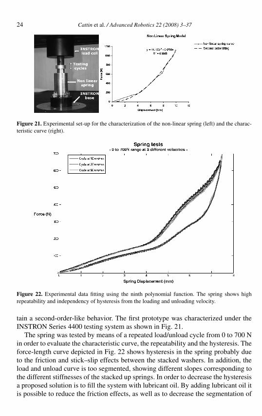