full discrete sliding mode controller for three phase pwm...
TRANSCRIPT

Full Discrete Sliding Mode Controller for Three Phase PWM Rectifier Based on Load Current Estimation
Jin YE1, Xu YANG, Member IEEE, Haizhong YE, Xiang HAO
School of Electrical Engineering Xi’an Jiaotong University
Xi’an, Shaanxi, CHINA 710049 e-mail1:[email protected]
Abstract – This paper presents a novel full discrete sliding mode controller for voltage-sourced three phase rectifier to improve its dynamic response under the load and dc link voltage variation. Using the concept of power balance in three phase rectifier, the sliding mode controller for dc link voltage regulation is derived. Also, in order to avoid the additional load current sensor, a new method to estimate the load current is introduced. In addition, an integral sliding mode controller is applied to regulate the inductor current. The control scheme was verified in a 5 kW lab prototype. The simulation and experimental results show that the proposed control scheme has the superior dynamic response and robustness over the PI controller.
Index Terms—Three phase rectifier, Dynamic Response, Power Balance, Sliding Mode Controller, Load Current Estimation.
I. INTRODUCTION Unity power factor converters have been widely used and
studied due to the increasing requirements of international standards such as IEEE-519. The aim of these controllers is to ensure a sinusoidal input current shape in phase with the line voltage and a particular voltage with low ripple. Boost-type three phase rectifiers among them is widely used and studied in last decades in industrial applications. The control of three phase rectifiers must achieve high performance in the sense of fast dynamic response to load variation, robustness to perturbations, none steady state error and low total harmonic distortion.
Conventional study has focused on the linear control of three phase rectifiers based on the small-signal models [1]-[3]. Proportional Integral (PI) regulators for both the output voltage control and inner current control have been proposed to achieve high steady state performance. However, its dynamic response is unsatisfactory because the high frequency components have been removed. Also, the design of PI controller is based on circuit parameters and thus it shows low robustness to parameter variation.
Recently, several control schemes based on a large-signal model of three phase rectifiers have been presented. Hysteretic control [4]-[5] for inner current loop provides a better way to deal with the large transients of rectifier and it is easy to design. Although well known for its stability and robustness toward parameters, line, and load variations, its variable frequency poses difficulties in the design of LC filters and thus the increasing switching loss cannot be avoided. Several improvements have been made to solve the
problem of variable frequency. However, it is at the expense of limited transient response. Predictive control [6]-[7] is gaining interest nowadays due to its possibility to include nonlinearities of the system in the predictive model. By calculating the behavior of the variables in different conduction states, the next period switching state can be obtained. However, the drawback of this approach lies in its sensitivity to parameters. Responses, with loads far from the nominal one, are not good enough and even suffer from instability. Sliding mode control [8]-[10] is also an alternative approach to the design of three phase rectifiers, which is suitable for switching converters based on time-varying circuit topology. By applying the sliding mode controller (SMC) into the current loop, the current loop enjoys faster transient response and better robustness. However, in most applications, SMC is only applied to the current loop, and the design of outer voltage loop is limited to PI controller [11], which is always dependent on system parameters and operating point. Thus even though the inner loop can achieve ideal performance, both the overall transient performance and robustness will be greatly undermined by the outer voltage regulation loop.
Considering the limitations of combining SMC with traditional linear control scheme, Fuzzy SMC [12] is proposed to overcome the drawbacks of PI controller. However, it is difficult to choose the optimal fuzzy sets and thus hard for practical implementation. In [13], a new voltage SMC has been proposed. Thus the dynamic response of the voltage loop is enhanced compared with traditional PI controllers. However, here comes at an expense of additional load current sensor as well as complicated approximation based on steady state. Considering the advantages of SMC in dealing with the nonlinear and transient response of the system, this approximation may result in deteriorated transient response. In addition, using hysteretic current control, variable switching frequency and increasing switching loss require considering. As this point of view, the control scheme is still a limited one.
In this paper, sliding mode control is applied to the dc link voltage loop as well as current loop. Based on the concept of power balance of the three phase converter, voltage SMC is proposed to enhance the dynamic response under the dc link voltage and load disturbance. Moreover, current integral SMC is utilized to achieve the lowest harmonic distortion and unity quality factor. A novel way of load current estimation is also provided to avoid additional load current sensor.
978-1-4244-5287-3/10/$26.00 ©2010 IEEE 2349

II. THEORETICAL DERIVATION
A. Mathematical model of three phase rectifier Fig. 1 shows a standard boost-type three-phase rectifier.
ai
bi
ci
L R1S
2S
3S
4S
5S
6S
ae
be
ce
C LRau
bu
cu
O
Fig. 1. Three phase PWM rectifier The switching states of the rectifier are determined by the
gating signals sa, sb, sc as follows.
1 2
1 2
1, if is on and is off0, if is off and is ona
S Ss
S S⎧
= ⎨⎩
(1)
3 4
3 4
1, if is on and is off0, if is off and is onb
S Ss
S S⎧
= ⎨⎩
(2)
5 6
5 6
1, if is on and is off0, if is off and is onc
S Ss
S S⎧
= ⎨⎩
(3)
Considering the displayed state variables on the circuit of
Fig.1, the following state-space model of three phase rectifier can be obtained.
, ,
, ,
, ,
13
13
13
a a dc a k ak a b c
b b dc b k bk a b c
c c dc c k ck a b c
dL i Ri v s s udt
dL i Ri v s s udt
dL i Ri v s s udt
=
=
=
⎛ ⎞= − − − +⎜ ⎟
⎝ ⎠⎛ ⎞
= − − − +⎜ ⎟⎝ ⎠⎛ ⎞
= − − − +⎜ ⎟⎝ ⎠
∑
∑
∑
(4)
where ia, ib, ic are A, B, C phase line current; ea, eb, ec, are A, B, C phase source voltage; R, L are the resistance and inductance; vdc is dc link voltage.
By applying the Park transformation, a rotating reference frame model of the three phase rectifier can now be written.
1 1
1 1
dd dc d q d
qq dc q d q
di Re v s i idt L L Ldi Re v s i idt L L L
ω
ω
⎧ = − + −⎪⎪⎨⎪ = − − −⎪⎩
(5)
where id, iq are the d and q components of the input current; ed, eq are d and q components of source voltage; ω is angular frequency; sd, sq are the d and q components of switching
state.
Once the switching frequency can be determined, the discrete standardized model can be obtained as follows.
*
*
( 1) ( ) ( )
( ) ( ) ( )( )
( ) ( ) ( )
( ) ( )( ) ( )
( ) ( )
D d d
Q q q
d ddc
q q
x k Ax k Bu k D
i k i k i kx k
i k i k i k
u k s ku k v k
u k s k
+ = + +
⎡ ⎤−⎡ ⎤= ⎢ ⎥⎢ ⎥ −⎢ ⎥⎣ ⎦ ⎣ ⎦⎡ ⎤ ⎡ ⎤
= =⎢ ⎥ ⎢ ⎥⎣ ⎦ ⎣ ⎦
= (6)
where
*
*
1;
1
0;
0
( ) ( )( )
;( )
( ( ))
d d
qd
RT TLA
RTTL
TLB
TL
e k Ri kT
L LDe k
T i kL
ω
ω
ω
⎡ ⎤− +⎢ ⎥= ⎢ ⎥⎢ ⎥− − +⎢ ⎥⎣ ⎦⎡ ⎤−⎢ ⎥
= ⎢ ⎥⎢ ⎥−⎢ ⎥⎣ ⎦⎡ ⎤
−⎢ ⎥⎢ ⎥=⎢ ⎥
−⎢ ⎥⎣ ⎦
T is the sample time; id
*(k), iq*(k) are the d and q current reference;
iD, iQ are the standardized d and q components of the input current.
B. Proposed SMC for dc link voltage regulation of three phase rectifier
In order to enhance the total transient response and robustness of the three phase rectifier, sliding mode controller is applied to the outer voltage loop. The aim of sliding mode controller for voltage loop is to find a suitable switching function which not only ensures the stability of the design, but also delivers a simpler calculation based on relatively precise model. The dc-link voltage dynamic response can be expressed in terms of the input-output power balance between its ac and dc sides
23 32 2
dcd d q q c dc
L
vi e i e i v
R+ = + (7)
dcc
dvi C
dt= (8)
where RL is the load resistance; ic is the capacitor current; C is the output capacitor.
Substituting (8) for (7), the voltage loop function can be obtained
2350

2 23 3 12 2 2
dc dcd d q q
L
dv vi e i e C
dt R+ = + (9)
Similarly, we can get discrete form of (9). 2 2 2( 1) ( ) ( )3 3 1( ) ( ) ( ) ( )
2 2 2dc dc dc
d d q qL
v k v k v ki k e k i k e k C
T R+ −
+ = +
(10) Assuming eq(k) = 0, we obtain discrete standardized
voltage loop function.
2
2 2
3 ( ) ( )2 2( 1) ( 1) ( ) ( )
( ) ( ) ( )
d dref
L L
dc ref
Ti k e kT Ty k y k v kR C R C C
y k v k v k
+ = − + − +
= −
(11) where vref(k) is the output voltage reference. The next step is to find switching surface which guarantees the stability of the sliding mode motion. The often used switching surface is as follows.
( ) ( )k Sy kσ = (12) where S is constant and S>0.
In order to guarantee the existence of the sliding regime of
the sliding surface, the reaching function should satisfy [14]
( )( ( 1) - ( )) 0k k kσ σ σ+ < (13) To undermine chattering caused by limited switching
frequency [14], we assume
( 1) ( ) ( ) sgn( ( ))k k qT k T kσ σ σ ε σ+ − = − − (14)
where q , ε are constant; q>0; ε>0;ε <<1; 1−qT>0.
Thus, substituting (12) and (14) for (11), id* (k) can be
obtained, assigning iq*(k) =0 to achieve unity power factor.
2
*
2 ( )[ ( ) sgn( ( ))] 2 ( )( )
3 ( )
ref
L Ld
d
v kC q k k y kS R R
i ke k
σ ε σ− − + += (15)
When the output voltage reaches the steady state, we
assume
( ) 0y k = (16) Thus, id
*(k) is as follows. 2
* 2 ( )( )
3 ( )ref
dd L
v ki k
e k R= (17)
From (17), we can find that the load resistance directly determines the tracking precision of the outer voltage loop. In order to achieve zero steady state error, high-precision load current sensor is required. Here, to avoid current sensor, a new way of load current estimation especially designed for voltage SMC is proposed.
Considering the uncertainty of the parameters and losses, (11) is modified to
2
2
2 2( 1) ( 1) ( ) ( ) ( )
2 ( )2( ) ( )
refL L
ref
L L
T Ty k y k v k h kR C R C
Tv kTh k y k P TR C R C Δ
+ = − + − +
= − − −Δ Δ
(18)
where LRΔ is load resistor uncertainty; PΔ is the total loss of three phase rectifier.
When the system comes to the switching surface, there is
( ) ( 1) 0k kσ σ= + = (19) Thus, the equivalent control [14] for the sliding mode is
obtained as
2 3 ( ) ( )( ) ( ) ( )
2 2d d L L
eq refi k e k R R C
y k v k h k= − + + (20)
By substituting (20) for (18), sliding mode equation is
derived as
( 1) ( ) 0y k y k+ = = (21)
Therefore, it is clearly shown that the dynamics of the sliding motion is unaffected by the variance of the load resistor. The load resistor only determines the tracking precision of the voltage loop. However, in practical applications, id is maintained in specific range. Thus the estimation of the load current should also be limited to the certain range.
We assume
( )d maxi k I< (22)
Also, we can easily get
( )( )
dcL
L
v kR
i k= (23)
Substituting (23) and (15) for (22), we obtain
3 ( ) [ ( ) sgn( ( )) / ]( )
2 ( )max d
Ldc
I e k C qy k k Si k
v kε σ+ − −
< (24)
where iL(k) is load current, Imax is the maximum line current.
Thus, in the steady state, the error of estimated load current
should be zero to ensure none steady error of voltage loop, while in dynamics, the limited error of the estimated load current would not affect the transient response of outer voltage controller. This makes the estimation of load current possible in three phase rectifier. From Fig. 2, without considering the dead time of the each leg, we can easily get
2351

C LR
3 ( )2 d d q qi s i s i= +
ci
Li
Fig. 2. Estimation of the load current
3( ) ( ( ) ( ) ( ) ( )) ( )2L d d q q ci k s k i k s k i k i k= + −
( 1) ( )( ) dc dc
cv k v k
i k CT
+ −= (25)
However, in real application, the estimated load current
contains high frequency components due to differentiation noise brought by capacitor current. Thus, a low pass filter is added to undermine the high frequency noise. Because the low pass filter will not affect the steady state of the load current, it will not affect the steady precision of the system. We get improved estimated load current
1( ) ( ) ( 1)1 1est L est
ai k i k i ka a
= + −+ +
(26)
where a is the low pass filter coefficient; iest(k) is the load estimation value.
C. Discrete integral SMC for inner current loop Integral sliding mode controller [15] is applied to the
current loop. The selection of switching function should satisfy both the stability of the sliding mode motion in the system and the desired steady-state dynamics. Thus, we choose integral switching surface for the current loop.
-1
0( ) ( ( )
i
kk Sx k CT x kσ
=
= + ∑) (27)
Where 1 1
2 2
0 0,
0 0s c
S Cs c
⎡ ⎤ ⎡ ⎤= =⎢ ⎥ ⎢ ⎥⎣ ⎦ ⎣ ⎦
, s1, s2>0, c1, c2>0
When the system comes to the switching surface, there is
( ) ( 1) 0k kσ σ= + = (28)
So, by substituting (28) for (27), sliding mode equation is derived as
-1( 1) ( - ) ( )x k I S CT x k+ = (29) Thus, the advantage of integral SMC is that it ensures the desired convergence velocity independent of system
parameters. By choosing appropriate S and C, both the dynamic response and robustness of current loop can be greatly enhanced. Also, in order to guarantee the existence of the sliding regime of the sliding surface, the reaching function should satisfy
( )( ( 1) - ( )) 0k k kσ σ σ+ < (30) Similarly, considering the stability of sliding mode and
chattering, we assume
( 1) ( ) ( ) sgn( ( ))k k qT k T kσ σ σ ε σ+ − = − − (31) where
1
2
1
2
0;
0
0;
0
q
εε
ε
⎡ ⎤= ⎢ ⎥⎣ ⎦⎡ ⎤
= ⎢ ⎥⎣ ⎦
q1,q2>0;ε1, ε2>0;1−q1T>0; 1−q2T>0.
By substituting (27) and (31) for (6), we finally get the desired switching state
[ ]-1( ) ( ) ( ) ( ) ( )( ) ( ) sgn( ( ))
u k SB SA CT S x k m km k qT k T k SDσ ε σ
= − + − += + +
(32)
To solve the problems of variable frequency in sliding
mode control, we combine SMC with SVPWM. The control diagram is shown in Fig. 3.
Fig. 3. Control diagram for three phase rectifier
D. Traditional PI controller for the current loop The control system for the current loop can be shown in
Fig.4.
1Ls
ip
KKs
+1.5 1
PWM dcK vTs +
dedi*
di
Fig. 4. Diagram of the control system for the inner current loop
The open loop transfer function for the current loop can be obtained
2352

2
1
(1.5 1)
p
i PWM dc ioi
K sK K v KWL s Ts
+= −
+ (33)
Where KPWM= 1/ 3 , Kp is the proportional gain of PI controller, Ki is the integral gain of PI controller, Woi is the open loop transfer function of the current loop.
Using the model of typical II system, we can get
2 2
12 (1.5 )
i PWM idc
i
K K v hL h T
+= (34)
where hi is bandwidth of the system.
Assuming hi=5, we can obtain
615
pPWM dc
LKTK v
= (35)
2
6112.5
iPWM dc
LKT K v
= (36)
E. Traditional PI controller for the voltage loop using SMC current controller We can get simplified close loop transfer function Wci for the current loop
15 1
ciWTs
=+
(37)
Considering the time delay, the control system for the voltage loop can be shown in Fig.5.
0.75Cs
ip
KKs
+ 16 1Ts +
dcv_dc refv
Li
Fig. 5. Diagram of the control system for the outer voltage loop
The open loop transfer function for the voltage loop can be
obtained
2
0.75 ( 1)
(6 1)
pi
iov
KK sKW
Cs Ts
+=
+ (38)
where Kp is the proportional gain of PI voltage controller, Ki is the integral gain of PI voltage controller
Similarly, we can obtain
7.5p
CKT
= (39)
2225i
CKT
= (40)
III. SIMULATION AND EXPERIMENTAL VERIFICATION To verify the proposed full-domain discrete sliding mode
controller, both a simulated model of power circuit and a real prototype has been built. Control and circuit parameters are illustrated in Table I, II and III. A digital platform using DSP TMS320F28335 has been set up for flexible implementation of different control methods. Both simulation results and experimental results of the salient waveforms are illustrated in the following figures.
A. Step change in d-axis current reference using PI current controller and sliding mode voltage controller
In this experiment, the d-axis current reference is changed from 10A to 15A and 15A to 10 A respectively. Fig. 6(a) and Fig. 6(b) show the experimental results with the d-axis current step change using the integral discrete sliding current controller and conventional PI controller respectively. Fig. 7(a) and Fig. 7(b) show simulation results with the d-axis current step change using the integral discrete sliding current controller and conventional PI controller respectively. In comparison, under d-axis reference step change from 10A to 15A, the response time of integral sliding mode controller with step change is nearly one third of that of PI current controller. Under d-axis reference step change from 15A to 10A, the response time of the proposed sliding mode current controller is less than one tenth of that of PI controller. Also, the proposed integral sliding mode controller demonstrates no overshoot.
B. Step change in dc link voltage reference using PI voltage controller and sliding mode voltage controller
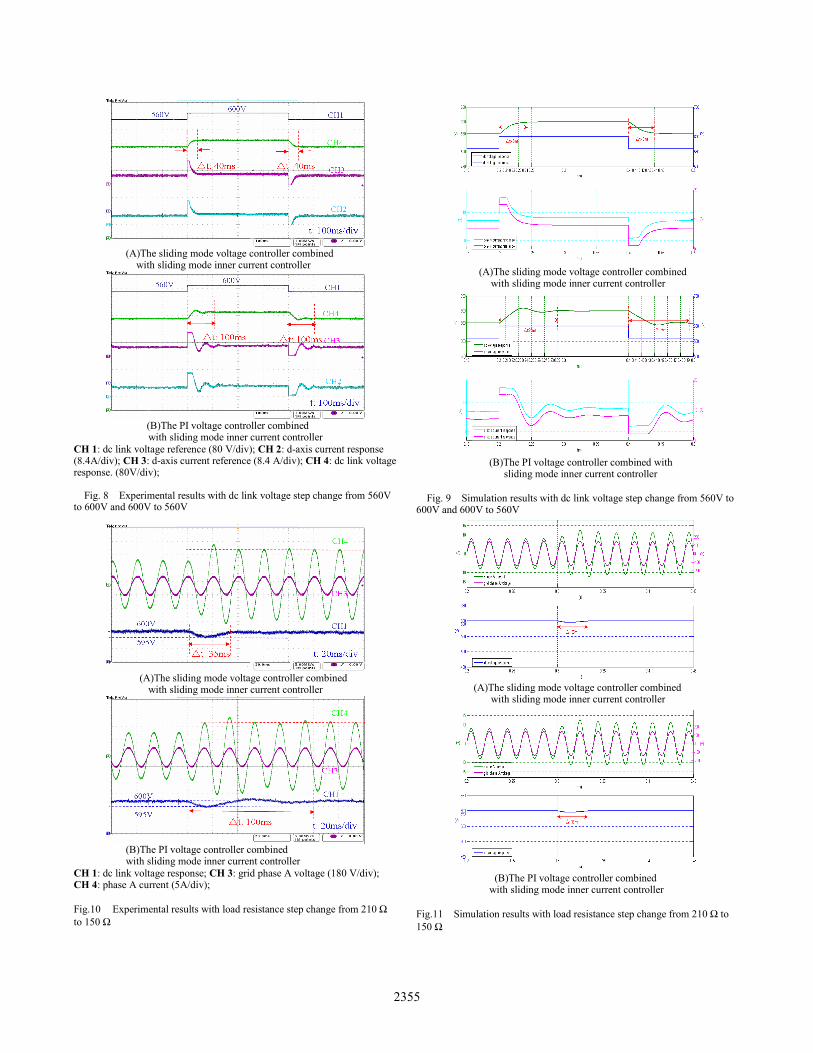
By applying the integral SMC into current loop, the comparisons of the PI voltage controller and sliding voltage controller are presented. In this experiment, the dc link voltage current reference is changed from 560V to 600V and 600V to 560V respectively. Fig. 8(a) and Fig. 8(b) show the experimental results with the dc link voltage step change using the discrete sliding voltage controller and conventional PI voltage controller respectively. Fig. 9(a) and Fig. 9(b) show the simulation results with the dc link voltage step change using the discrete sliding voltage controller and conventional PI voltage controller respectively. As is shown in Fig. 7, the SMC voltage controller presents no steady error, no voltage overshoot and no current oscillation, faster response time (0.04s). Under the same voltage step change, PI controller gives undesirable response time (nearly 2.5 times as much as SMC) and deteriorated transient performance (oscillation and the voltage overshoot).
C. Step change in load using PI voltage controller and sliding mode voltage controller
This experiment is designed to verify the proposed load current estimation and the robustness of the proposed voltage SMC to parameter variation. The resistor load is changed
2353

from 210 Ω to 150 Ω. Fig. 10(a) and Fig. 10(b) show the experimental results with the load step change using the discrete sliding voltage controller and conventional PI voltage controller respectively. Fig. 11(a) and Fig. 11(b) show the simulation results with the dc link voltage step change using the discrete sliding voltage controller and conventional PI voltage controller respectively. Comparison of the SMC and PI controller under load variations shows that SMC is less sensitive to parameters and has stronger robustness. Also, it attests to the validity of load current estimation specifically designed for SMC.
TABLE I PARAMETERS OF CIRCUIT
Circuit Parameters Value
Switching Frequency 10kHz L 9.2mH C 1680μF RL 210Ω/150Ω
Grid Phase A Voltage 200V Rated Dc Link Voltage 560V/600V
(A) The proposed sliding mode current controller
(B) The PI current controller
CH 1: d-axis current reference (8.4 A/div); CH 2: d-axis current response (8.4A/div); CH 3: grid phase-A voltage (180 V/div); CH 4: phase-A current (5 A/div);
Fig. 6. Experimental results with d-axis current step change from 10A to 15 A and 15 A to 10A in three phase PWM rectifier
TABLE II
PARAMETERS OF PI CONTROLLER
Parameters PI current controller
PI voltagecontroller
Kp 0.1062 1.032Ki 141.64 242.2
TABLE III PARAMETERS OF SMC CONTROLLER
Parameters Inner SMC Outer SMC
ε 0.01 0
0 0.01⎡ ⎤⎢ ⎥⎣ ⎦
0.01
S 0.1 00 0.1
⎡ ⎤⎢ ⎥⎣ ⎦
1
C 0.001 0
0 0.001⎡ ⎤⎢ ⎥⎣ ⎦
0
q 3000 0
0 3000⎡ ⎤⎢ ⎥⎣ ⎦
40
(A) The proposed sliding mode current controller
(B) The PI current controller Fig. 7. Simulation results with d-axis current step change from 10A to
15 A and 15 A to 10A in three phase PWM rectifier
2354
(A)The sliding mode voltage controller combined
with sliding mode inner current controller
(B)The PI voltage controller combined with sliding mode inner current controller
CH 1: dc link voltage reference (80 V/div); CH 2: d-axis current response (8.4A/div); CH 3: d-axis current reference (8.4 A/div); CH 4: dc link voltage response. (80V/div);
Fig. 8 Experimental results with dc link voltage step change from 560V to 600V and 600V to 560V
(A)The sliding mode voltage controller combined
with sliding mode inner current controller
(B)The PI voltage controller combined with sliding mode inner current controller
CH 1: dc link voltage response; CH 3: grid phase A voltage (180 V/div); CH 4: phase A current (5A/div); Fig.10 Experimental results with load resistance step change from 210 Ω to 150 Ω
(A)The sliding mode voltage controller combined
with sliding mode inner current controller
(B)The PI voltage controller combined with
sliding mode inner current controller
Fig. 9 Simulation results with dc link voltage step change from 560V to 600V and 600V to 560V
(A)The sliding mode voltage controller combined
with sliding mode inner current controller
(B)The PI voltage controller combined with sliding mode inner current controller
Fig.11 Simulation results with load resistance step change from 210 Ω to 150 Ω
2355

IV. CONCLUSION In the paper, a full sliding mode controller for three phase
rectifier is presented. For the design of SMC current controller, the selection of integral switching surface is analyzed and proved to be useful from the view of long-term stability and the speed of response. By applying integral discrete sliding mode algorithm for the inductor current loop, the current loop presents more satisfactory dynamic response under current reference disturbance compared with conventional PI controller. Also, using the power balance equations, a new choice of the switching surface was proposed for the voltage loop controller, which demands no complicated calculation. Experimental and simulation results show that the proposed discrete sliding mode controller for the voltage regulation shows better dynamic response concerning response time, overshoot, and oscillation over PI controller under the dc link voltage step change. In addition, the proposed voltage SMC has better robustness toward parameter variation. Further, the validity of the proposed load current estimation is verified based on the desirable dynamic performance of voltage SMC under load variation.
REFERENCES [1] A. W. Green, J.T. Boys, and G. F. Gates, "3-phase voltage source
reversible rectifier," Proc. Elect. Eng., vol. 135, pt. B, no. 6, pp.362-370, 1988.
[2] H. Kohlmeier and D. Schroder, "Control of a double voltage inverter system coupling a three phase mains with an AC-drive," in Proc. 1987 IEEE-LAS Conf., pp. 593-599.
[3] C. T. Rim, N. S. Choi, G. C. Cho, and G. H. Cho, “A complete DC and AC analiysis of three-phase controlled-current PWM rectifier using circuit D-Q transformation,”IEEE Trans. Power Electron., vol. 9, pp.390–396, Jul. 1994.
[4] M. S. Dawande, V. R. Kanetkar, and G. K. Dubey, “Three phase switch mode rectifier with hysteresis current control,”IEEE Trans. Power Electron., vol. 11, pp.466–471, May. 1996.
[5] B. T. Ooi, J. C. Salmon, J. W. Dixon, and A. B. Kulkarni, “A three phase controlled-current PWM converter with leading power factor,” IEEE Trans. Ind. Applicat., vol. IA-23, pp. 78–84, Jan./Feb. 1987.
[6] O. Kukrer, “Discrete-time current control of voltage-fed three phase PWM inverters,”IEEE Trans. Power Electron., vol. 11, pp.260–269, Mar. 1996.
[7] J. Rodríguez, J. Pontt, C. A. Silva, P. Correa, P. Lezana, P. Cortés, and U.Ammann “Predictive current control of a voltage source inverter,”IEEE Trans. Industrial Electron., vol. 54, pp.495–503, Feb. 2007.
[8] M. Carpita, and A.Ricerche “Sliding mode controlled inverter with switching techniques,” EPE., vol. 4, no. 3, pp.30–35, Sep.1994.
[9] J. F. Silva “Sliding mode control design of drive and regulation electronics for power converters,” J.Circuits, Syst., Comput., vol. 5, no. 3, pp.355–371, Sep.1995.
[10] S. C. Tan, Y. M. Lai, C. K. Tse, and M. K. Cheung, “Adaptive feed-forward and feedback control schemes for sliding mode controlled power converters,” IEEE Trans. Power Electron., vol. 21, no. 1, pp.182–192, Jan.2006.
[11] D .M .Vilathgamura, S .R .Wall, and R .D .Jackson, “Variable structure control of voltage sourced reversible rectifiers, ” in Proc. 1996, IEE . Electric Power Applications Conf., pp. 18-24.
[12] H .Y .Yu, Q. Hu, and X.Y Ding , “Fuzzy sliding mode variable structure control of three-phase rectifier ,” in Proc. 2007, FSKD Conf., pp. 581-585.
[13] J. F. Silva, “Sliding-mode control of boost-type unity-power-factor PWM Rectifiers,” IEEE Trans. Industrial Electron., vol. 46, no. 3, pp.594–603, Jun.1999.
[14] W. B. Gao, and J. C. Hung, “Variable structure control of nonlinear systems: a new approach,” IEEE Trans. Industrial Electron., vol. 40, no. 1, pp.45–55, Feb.1993.
[15] K. Abidi, J. X. Xu, and X.H.Yu, “On the discrete-time integral sliding mode control ,” in Proc. 2006, IEEE International Workshop on Variable Structure Systems Conf., pp. 29-34.
2356