fukushima floating offshore windfind farm...
TRANSCRIPT

Fukushima Floating Offshore Wind FarmFukushima Floating Offshore Wind Farm Demonstration Project
(Fukushima FORWARD)(Fukushima FORWARD)
Takeshi ISHIHARATakeshi ISHIHARAThe University of Tokyo
0

Contents
Background and objective
Technical challenges and solutions
Social acceptance and collaboration Social acceptance and collaboration
C l i d ti Conclusion and perspectives
1
Background
BenefitsOffshore wind energy potential 400
500
0-20ml (G
W)
Water depth
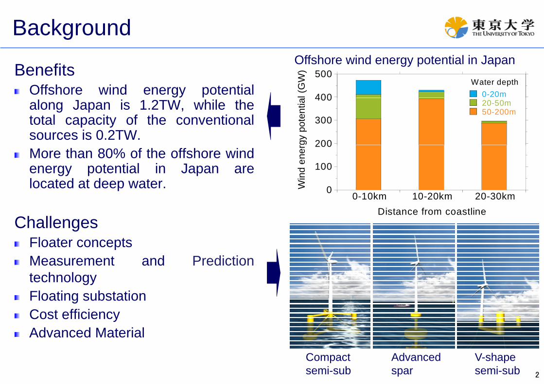
Offshore wind energy potential in Japan
along Japan is 1.2TW, while thetotal capacity of the conventionalsources is 0.2TW.
200
300
400 20-50m50-200m
gy p
oten
tia
More than 80% of the offshore windenergy potential in Japan arelocated at deep water. 0
100
200
Win
d en
er
ChallengesFl t t
00-10km 10-20km 20-30km
Distance from coastline
Floater conceptsMeasurement and PredictiontechnologyFloating substationCost efficiencyAdvanced Material
2
Advanced Material
Compact semi-sub
V-shape semi-sub
Advanced spar

Fukushima FORWARD project
Ideal area for floating offshore windLarge wind energy potential at 20km 50km fromLarge wind energy potential at 20km-50km fromcoast, where water depth is 100m–200m
Strong power grid for nuclear and thermal power g p g pplants
Port facilities available
設備利用率
25.0 - 30.0%
30.0 - 35.0%
35.0 - 40.0%
40.0 - 45.0%
BenefitsThe accumulation of wind energy industry will help
0 20 40 60 8010km
the restoration of this region.
7.4m/s (offshore) 4.3m/s (onshore)
3

Facility specifications of FORWARD projectFacility Name Scale Wind Turbine type Floater type Project Term
Floating Wind Turbine I 2MW Downwind Type Compact Semi-Sub First
Floating Wind Turbine II 7MW Upwind Type V-shape Semi-Sub Secondg p yp p
Floating Wind Turbine III 7MW Upwind Type Advanced Spar Second
Floating Substation 25MVA/66kV Substation Advanced Spar First
Substation 4 Colum Semi-Sub Advanced Spar 3 Colum Semi-Sub
4

Work packages1 Preliminary study Phase I
• site assessment• preliminary design
5 Operation & Maintenance• floater / mooring• wind turbine
2 Measurement / prediction 6 Environment issue
• preliminary design • substation / power cable
• environmental assessment• marine navigation safety• collaboration with fishery
• metocean• floater motion• substation / power cable
3 Floating wind turbines 7 DocumentationPhase II
• wind turbine• floater / mooring
• technical review• manual
4 Grid integration 8 Public relation
floater / mooring• advanced material • project report
• communication centre• floating substation• dynamic cables
• communication centre• seminar and symposium
5

Presentation of consortium membersConsortium Member Main Rule
Marubeni Corporation 【Project Integrator】Pre-Studies, Approval and Licensing, Operation andMaintenance, Collaboration with Fishery Industry
The University of Tokyo 【Technical Advisor】Measurement and Prediction Technology, NavigationSafety, Public relationSafety, Public relation
Mitsubishi Corporation Pre-Studies, Approval and Licensing, EnvironmentalAssessment
Mitsubishi Heavy Industries, Ltd. V-Shape Semi-Sub Type Floater
IHI Marine United Inc. Advanced Spar Type Floater and Floating Substation
Mitsui Engineering & Shipbuilding Co., Ltd. Compact Semi-Sub Type Floater
Nippon Steel Corporation Advanced Steelpp p
Hitachi, Ltd. Floating Electric Power Substation
Furukawa Electric Co., Ltd. Undersea and Dynamic Cables
Shimizu Corporation Pre-Studies Construction and Installation TechnologyShimizu Corporation Pre-Studies, Construction and Installation Technology
Mizuho Information & Research Institute, Inc. Documentation, Committee Operations
6

FORWARD vision and challengesGreen growth in Fukushima• Industry accumulation• Employment• Employment• Restoration
Fukushima FORWARD
Technical challenge Social acceptance• Floater concepts• Measurement and prediction
• Navigation safety• Environmental assessmentMeasurement and prediction
• Floating substation• Cost efficiency• Advanced material
• Environmental assessment• Collaboration with fishery• Public relation
• Advanced material
7

Development phases and key success factors
Phase I (2011~2013) Phase II (2014~2015)
2 Phases:
( ) ( )
Floating substationCompact semi-sub (2MW)
V-shape semi-sub (7MW)Advanced spar (7MW)
Phase I
1,850mV-shapesemi-sub
Floating substationPhase II
Compact semi-sub V-shape semi-subAdvanced spar
1,480m
1 480
Floatingsubstation
Compactsemi-sub
Transmissioncable
1,480m
Advancedspar
D i / T t / I t C t ffi i / i d t i li ti
3 key success factors:
18Technology maturity / Social acceptance
Design / Test / Improvement Cost efficiency / industrialization

Thank you for your attention
20