fuels and furnaces - website cá nhân giáo viêns standard... · fuels and furnaces by ......
TRANSCRIPT

Section 7Fuels and Furnaces
Copyright (C) 1999 by The McGraw-Hill Companies, Inc. All rights reserved. Use ofthis product is subject to the terms of its License Agreement. Click here to view.
BY
MARTIN D. SCHLESINGER Wallingford Group, Ltd.KLEMENS C. BACZEWSKI Consulting EngineerGLENN W. BAGGLEY Manager, Regenerative Systems, Bloom Engineering Co., Inc.CHARLES O. VELZY ConsultantROGER S. HECKLINGER Project Director, Roy F. Weston of New York, Inc.GEORGE J. RODDAM Sales Engineer, Lectromelt Furnace Division, Salem Furnace Co.
7.1 FUELSby Martin D. Schlesinger and Associates
Coal (BY M. D. SCHLESINGER) . . . . . . . . . . . . . . . . . . . . . . . . . . . . . . . . . . . 7-2Biomass Fuels (BY M. D. SCHLESINGER) . . . . . . . . . . . . . . . . . . . . . . . . . . . 7-8
Heat-Saving Methods . . . . . . . . . . . . . . . . . . . . . . . . . . . . . . . . . . . . . . . . . . . 7-44Special Atmospheres . . . . . . . . . . . . . . . . . . . . . . . . . . . . . . . . . . . . . . . . . . . 7-45
Petroleum and Other Liquid Fuels (BY JAMES G. SPEIGHT) . . . . . . . . . . . . . 7-10Gaseous Fuels (BY JAMES G. SPEIGHT) . . . . . . . . . . . . . . . . . . . . . . . . . . . . . 7-14Synthetic Fuels (BY M. D. SCHLESINGER) . . . . . . . . . . . . . . . . . . . . . . . . . . . 7-16Explosives (BY J. EDMUND HAY) . . . . . . . . . . . . . . . . . . . . . . . . . . . . . . . . . 7-19Dust Explosions (BY HARRY C. VERAKIS AND JOHN NAGY) . . . . . . . . . . . . 7-22
7.4 INCINERATIONby Charles O. Velzy and Roger S. Hecklinger
Nature of the Fuel . . . . . . . . . . . . . . . . . . . . . . . . . . . . . . . . . . . . . . . . . . . . . . 7-45Types of Furnaces . . . . . . . . . . . . . . . . . . . . . . . . . . . . . . . . . . . . . . . . . . . . . 7-46
Rocket Fuels (BY RANDOLPH T. JOHNSON) . . . . . . . . . . . . . . . . . . . . . . . . . 7-28
7.2 CARBONIZATION OF COAL AND GAS MAKINGby Klemens C. Baczewski
Carbonization of Coal . . . . . . . . . . . . . . . . . . . . . . . . . . . . . . . . . . . . . . . . . . 7-31Carbonizing Apparatus . . . . . . . . . . . . . . . . . . . . . . . . . . . . . . . . . . . . . . . . . . 7-33Gasification . . . . . . . . . . . . . . . . . . . . . . . . . . . . . . . . . . . . . . . . . . . . . . . . . . . 7-35
7.3 COMBUSTION FURNACESby Glenn W. Baggley
Fuels . . . . . . . . . . . . . . . . . . . . . . . . . . . . . . . . . . . . . . . . . . . . . . . . . . . . . . . . 7-41Types of Industrial Heating Furnaces . . . . . . . . . . . . . . . . . . . . . . . . . . . . . . 7-41Size and Economy of Furnaces. . . . . . . . . . . . . . . . . . . . . . . . . . . . . . . . . . . . 7-42Furnace Construction . . . . . . . . . . . . . . . . . . . . . . . . . . . . . . . . . . . . . . . . . . . 7-44
Plant Design . . . . . . . . . . . . . . . . . . . . . . . . . . . . . . . . . . . . . . . . . . . . . . . . . . 7-46Furnace Design . . . . . . . . . . . . . . . . . . . . . . . . . . . . . . . . . . . . . . . . . . . . . . . . 7-46Combustion Calculations . . . . . . . . . . . . . . . . . . . . . . . . . . . . . . . . . . . . . . . . 7-49Recovery . . . . . . . . . . . . . . . . . . . . . . . . . . . . . . . . . . . . . . . . . . . . . . . . . . . . . 7-51
7.5 ELECTRIC FURNACES AND OVENSby George J. Roddam
Classification and Service . . . . . . . . . . . . . . . . . . . . . . . . . . . . . . . . . . . . . . . 7-52Resistor Furnaces . . . . . . . . . . . . . . . . . . . . . . . . . . . . . . . . . . . . . . . . . . . . . . 7-52Dielectric Heating . . . . . . . . . . . . . . . . . . . . . . . . . . . . . . . . . . . . . . . . . . . . . . 7-55Induction Heating . . . . . . . . . . . . . . . . . . . . . . . . . . . . . . . . . . . . . . . . . . . . . . 7-55Arc Furnaces . . . . . . . . . . . . . . . . . . . . . . . . . . . . . . . . . . . . . . . . . . . . . . . . . . 7-55Induction Furnaces . . . . . . . . . . . . . . . . . . . . . . . . . . . . . . . . . . . . . . . . . . . . . 7-55Power Requirements for Electric Furnaces . . . . . . . . . . . . . . . . . . . . . . . . . . 7-58Submerged-Arc and Resistance Furnaces . . . . . . . . . . . . . . . . . . . . . . . . . . . 7-59
7-1

7.1 FUELSby Martin D. Schlesinger and Associates
COALby Martin D. SchlesingerWallingford Group, Ltd.
REFERENCES: Petrography of American Coals, U.‘‘Chemistry of Coal Utilization,’’ Wiley. ASTM, ‘Coal and Coke.’’ Methods of Analyzing and TBuMines Bull. 638. Karr, ‘‘Analytical Methods fAcademic. Preprints, Division of Fuel Chemistry, A
structure and composition. It usually is slow to ignite and difficult toburn. It has little commercial importance.
Anthracite, sometimes called hard coal, is hard, compact, and shinyblack, with a generally conchoidal fracture. It ignites with some diffi-
hort, smokeless, blue flame. Anthracite is usedng and as a source of carbon. It is also used in
Copyright (C) 1999 by The McGraw-Hill Companies, Inc. All rights reserved. Use ofthis product is subject to the terms of its License Agreement. Click here to view.
S. BuMines Bull. 550. Lowry,‘Standards on Gaseous Fuels,esting Coal and Coke, U.S.or Coal and Coal Products,’’
merican Chemical Society.
culty and burns with a sprimarily for space heati
Coal is a black or brownish-black combustible solid formed by thedecomposition of vegetation in the absence of air. Microscopy canidentify plant tissues, resins, spores, etc. that existed in the originalstructure. It is composed principally of carbon, hydrogen, oxygen, andsmall amounts of sulfur and nitrogen. Associated with the organic ma-trix are water and as many as 65 other chemical elements. Many traceelements can be determined by spectrometric method D-3683. Coal isused directly as a fuel, a chemical reactant, and a source of organicchemicals. It can also be converted to liquid and gaseous fuels.
Classification and Description
Coal may be classified by rank, by variety, by size and sometimes byuse. Rank classification takes into account the degree of metamorphismor progressive alteration in the natural series from lignite to anthracite.Table 7.1.1 shows the classification of coals by rank adopted as stan-dard by the ASTM (method D-388). The basic scheme is according tofixed carbon (FC) and heating value (HV) from a proximate analysis,calculated on the mineral-matter-free (mmf ) basis. The higher-rankcoals are classified according to the FC on a dry basis and the lower-rank according to HV in Btu on a moist basis. Agglomerating character isused to differentiate between certain adjacent groups. Coals are consid-ered agglomerating if, in the test to determine volatile matter, theyproduce either a coherent button that will support a 500-g weight or abutton that shows swelling or cell structure.
For classifying coals according to rank, FC and HV can be calculatedto a moisture-free basis by the Parr formulas, Eqs. (7.1.1) to (7.1.3)below:
FC (dry, mmf ) 5FC 2 0.15S
100 2 (M 1 1.08A 1 0.55S)3 100 (7.1.1)
VM (dry, mmf ) 5 100 2 FC (7.1.2)
HV (moist, mmf ) 5Btu 2 50S
100 2 (1.08A 1 0.55S)(7.1.3)
where FC 5 percentage of fixed carbon, VM 5 percentage of volatilematter, M 5 percentage of moisture, A 5 percentage of ash, S 5 per-centage of sulfur, all on a moist basis. ‘‘Moist’’ coal refers to the naturalbed moisture, but there is no visible moisture on the surface. HV 5heating value, Btu/lb (Btu/lb 3 0.5556 5 g ?cal/g). Because of its com-plexity, the analysis of coal requires care in sampling, preparation, andselection of the method of analysis.
Figure 7.1.1 shows representative proximate analyses and heatingvalues of various ranks of coal in the United States. The analyses werecalculated to an ash-free basis because ash is not a function of rank.Except for anthracite, FC and HV increase from the lowest to the high-est rank as the percentages of volatile matter and moisture decrease. Thesources and analyses of coals representing various ranks are given inTable 7.1.2.
Meta-anthracite is a high-carbon coal that approaches graphite in
7-2
Fig. 7.1.1 Proximate analysis and heating values of various ranks of coal (ash-free basis).
electric power generating plants in or close to the anthracite-producingarea. The iron and steel industry uses some anthracite in blends withbituminous coal to make coke, for sintering iron-ore fines, for liningpots and molds, for heating, and as a substitute for coke in foundries.
Semianthracite is dense, but softer than anthracite. It burns with ashort, clean, bluish flame and is somewhat more easily ignited thananthracite. The uses are about the same as for anthracite.
Low-volatile bituminous coal is grayish black, granular in structure andfriable on handling. It cakes in a fire and burns with a short flame that isusually considered smokeless under all burning conditions. It is used forspace heating and steam raising and as a constituent of blends for im-proving the coke strength of higher-volatile bituminous coals. Low-volatile bituminous coals cannot be carbonized alone in slot-type ovensbecause they expand on coking and damage the walls of the ovens.
Medium-volatile bituminous coal is an intermediate stage betweenhigh-volatile and low-volatile bituminous coal and therefore has someof the characteristics of both. Some are fairly soft and friable, but othersare hard and do not disintegrate on handling. They cake in a fuel bed andsmoke when improperly fired. These coals make cokes of excellentstrength and are either carbonized alone or blended with other bitumi-nous coals. When carbonized alone, only those coals that do not expandappreciably can be used without damaging oven walls.
High-volatile A bituminous coal has distinct bands of varying luster. Itis hard and handles well with little breakage. It includes some of the beststeam and coking coal. On burning in a fuel bed, it cakes and gives offsmoke if improperly fired. The coking property is often improved byblending with more strongly coking medium- and low-volatile bitumi-nous coal.
High-volatile B bituminous coal is similar to high-volatile A bituminouscoal but has slightly higher bed moisture and oxygen content and is lessstrongly coking. It is good coal for steam raising and space heating.

Table 7.1.1 Classification of Coals by Rank (ASTM D388)*
Fixed-carbon limits, Volatile-matter Calorific value limits,percent limits, percent Btu/lb (moist,†
(dry, mineral-matter- (dry, mineral-matter- mineral-matter-free basis) free basis) free basis)
Equal or Equal or Equal orgreater Less Greater less greater Less Agglomerating
Class Group than than than than than than character
I. Anthracitic 1. Meta-anthracite 98 . . . . . . 22. Anthracite 92 98 2 83. Semianthracite 86 92 8 14 . . . . . . . . . . . . . Nonagglomerating‡
II. Bituminous 1. Low-volatile bituminous coal 78 86 14 22 . . . . . . . . . . . . .2. Medium-volatile bituminous coal 69 78 22 31 . . . . . . . . . . . . .3. High-volatile A bituminous coal . . . 69 31 . . . 14,000§ . . . . . .
Commonlyagglomerating¶4. High-volatile B bituminous coal . . . . . . . . . . . . 13,000§ 14,000
5. High-volatile C bituminous coal . . . . . . . . . . . . H 11,500 13,00010,500 11,500 Agglomerating
III. Subbituminous 1. Subbituminous A coal . . . . . . . . . . . . 10,500 11,500 Nonagglomerating2. Subbituminous B coal . . . . . . . . . . . . 9,500 10,5003. Subbituminous C coal . . . . . . . . . . . . 8,300 9,500
IV. Lignitic 1. Lignite A . . . . . . . . . . . . 6,300 8,3002. Lignite B . . . . . . . . . . . . . . . . . . . 6,300
* This classification does not include a few coals, principally nonbanded varieties, which have unusual physical and chemical properties and which come within the limits of fixed-carbon or calorific value of the high-vola-tile bituminous and subbituminous ranks. All of these coals either contain less than 48 percent dry, mineral-matter-free fixed carbon or have more than 15,500 moist, mineral-matter-free British thermal units per pound. Btu/lb 32.323 5 kJ/kg.
† Moist refers to coal containing its natural inherent moisture but not including visible water on the surface of the coal.‡ If agglomerating, classify in low-volatile group of the bituminous class.§ Coals having 69 percent or more fixed carbon on the dry, mineral-matter-free basis are classified according to fixed carbon, regardless of calorific value.¶ It is recognized that there may be nonagglomerating varieties in these groups of the bituminous class, and there are notable exceptions in the high-volatile C bituminous group.
7-3
Copyright (C
) 1999 by The M
cGraw
-Hill C
ompanies, Inc. A
ll rights reserved. Use of
this product is subject to the terms of its L
icense Agreem
ent. Click here to view
.

Table 7.1.2 Sources and Analyses of Various Ranks of Coal as Received
Proximate, % Ultimate, %
Classification by Volatile FixedCalorific
value,rank State County Bed Moisture matter carbon Ash† Sulfur Hydrogen Carbon Nitrogen Oxygen Btu/lb*
Meta-anthracite Rhode Island Newport Middle 13.2 2.6 65.3 18.9 0.3 1.9 64.2 0.2 14.5 9,310Anthracite Pennsylvania Lackawanna Clark 4.3 5.1 81.0 9.6 0.8 2.9 79.7 0.9 6.1 12,880Semianthracite Arkansas Johnson Lower Hartshorne 2.6 10.6 79.3 7.5 1.7 3.8 81.4 1.6 4.0 13,880Low-volatilebituminouscoal
West Virginia Wyoming Pocahontas no. 3 2.9 17.7 74.0 5.4 0.8 4.6 83.2 1.3 4.7 14,400
Medium-volatilebituminouscoal
Pennsylvania Clearfield Upper Kittanning 2.1 24.4 67.4 6.1 1.0 5.0 81.6 1.4 4.9 14,310
High-volatile Abituminouscoal
West Virginia Marion Pittsburgh 2.3 36.5 56.0 5.2 0.8 5.5 78.4 1.6 8.5 14,040
High-volatile Bbituminouscoal
Kentucky,western field
Muhlenburg No. 9 8.5 36.4 44.3 10.8 2.8 5.4 65.1 1.3 14.6 11,680
High-volatile Cbituminouscoal
Illinois Sangamon No. 5 14.4 35.4 40.6 9.6 3.8 5.8 59.7 1.0 20.1 10,810
SubbituminousA coal
Wyoming Sweetwater No. 3 16.9 34.8 44.7 3.6 1.4 6.0 60.4 1.2 27.4 10,650
SubbituminousB coal
Wyoming Sheridan Monarch 22.2 33.2 40.3 4.3 0.5 6.9 53.9 1.0 33.4 9,610
SubbituminousC coal
Colorado El Paso Fox Hill 25.1 30.4 37.7 6.8 0.3 6.2 50.5 0.7 35.5 8,560
Lignite North Dakota McLean Unnamed 36.8 27.8 29.5 5.9 0.9 6.9 40.6 0.6 45.1 7,000
* Btu/lb 3 2.325 5 J/g; Btu/lb 3 0.5556 5 g ?cal/g.† Ash is part of both the proximate and ultimate analyses.
7-4
Copyright (C
) 1999 by The M
cGraw
-Hill C
ompanies, Inc. A
ll rights reserved. Use of
this product is subject to the terms of its L
icense Agreem
ent. Click here to view
.

COAL 7-5
Some of it is blended with more strongly coking coals for makingmetallurgical coke.
High-volatile C bituminous coal is a stage lower in rank than the Bbituminous coal and therefore has a progressively higher bed moistureand oxygen content. It is used primarily for steam raising and spaceheating.
Subbituminous coals usually show less evidence of banding than bitu-minous coals. They have a high moisture content, and on exposure toair, they disintegrate or ‘‘slack’’ because of shrinkage from loss of
but this moisture usually is considered part of the coal substance. Themoisture obtained by the standard method consists of (1) surface orextraneous moisture that may come from external sources such as per-colating waters in the mine, rain, condensation from the air, or waterfrom a coal washery; (2) inherent moisture, sometimes called bed mois-ture, which is so closely held by the coal substance that it does notseparate these two types of moisture. A coal may be air-dried at roomtemperature or somewhat above, thereby determining an ‘‘air-dryingloss,’’ but this result is not the extraneous moisture because part of the
l. Aous
Copyright (C) 1999 by The McGraw-Hill Companies, Inc. All rights reserved. Use ofthis product is subject to the terms of its License Agreement. Click here to view.
moisture. They are noncaking and noncoking, and their primary use isfor steam raising and space heating.
Lignites are brown to black in color and have a bed moisture contentof 30 to 45 percent with a resulting lower heating value than higher-rankcoals. Like subbituminous coals, they have a tendency to ‘‘slack’’ ordisintegrate during air drying. They are noncaking and noncoking. Lig-nite can be burned on traveling or spreader stokers and in pulverizedform.
The principal ranks of coal mined in the major coal-producing statesare shown in Table 7.1.3. Their analyses depend on several factors, e.g.,source, size of coal, and method of preparation. Periodic reports areissued by the U.S. Department of Energy, Energy Information Agency.They provide statistics on production, distribution, end use, and analyti-cal data.
Composition and Characteristics
Proximate analysis, sulfur content, and calorific values are the analyti-cal determination most commonly used for industrial characterizationof coal. The proximate analysis is the simplest means for determining thedistribution of products obtained during heating. It separates the prod-ucts into four groups: (1) water or moisture, (2) volatile matter consist-ing of gases and vapors, (3) fixed carbon consisting of the carbonizedresidue less ash, and (4) ash derived from the mineral impurities in thecoal. ASTM methods D3712 and D5142 are used; the latter is an instru-mental method.
Moisture is the loss in weight obtained by drying the coal at a temper-ature between 104 and 110°C (220 and 230°F) under prescribed condi-tions. Further heating at higher temperatures may remove more water,
Table 7.1.3 Principal Ranks of Coal Mined in Various States*
Semi- Low-volatile Medium-vol. High-voState Anthracite anthracite bituminous bituminous bitumin
Alabama x xAlaskaArkansas x x x xColorado xIllinois x
IndianaIowaKansas xKentuckyEastern xWestern x
Maryland x x xMissouriMontanaNew Mexico xNorth DakotaOhio xOklahoma x x xPennsylvania x x x x xSouth DakotaTennessee x xTexasUtah xVirginia x x x xWashington xWest Virginia x x xWyoming
* Compiled largely from Typical Analyses of Coals of the United States, BuMines Bull. 446, and
inherent moisture also vaporizes during the drying.Mine samples taken at freshly exposed faces in the mine, which are
free from visible surface moisture, give the best information as to inher-ent or bed moisture content. Such moisture content ranges in value from2 to 4 percent for anthracite and for bituminous coals of the easternAppalachian field, such as the Pocahontas, Sewell, Pittsburgh, Freeport,and Kittaning beds. In the western part of this field, especially in Ohio,the inherent moisture ranges from 4 to 10 percent. In the interior fieldsof Indiana, Illinois, western Kentucky, Iowa, and Missouri, the range isfrom 8 to 17 percent. In subbituminous coals the inherent moistureranges from 15 to 30 percent, and in lignites from 30 to 45 percent. Thetotal amount of moisture in commercial coal may be greater or less thanthat of the coal in the mine. Freshly mined subbituminous coal andlignite lose moisture rapidly when exposed to the air. The extraneous orsurface moisture in coal is a function of the surface exposed, eachsurface being able to hold a film of moisture. Fine sizes hold moremoisture than lump. Coal which in the mine does not contain more than4 percent moisture may in finer sizes hold as much as 15 percent; thesame coal in lump sizes, even after underwater storage, may containlittle more moisture than originally in the mine.
In the standard method of analysis, the volatile matter is taken as theloss in weight, less moisture, obtained by heating the coal for 7 min in acovered crucible at about 950°C (1,742°F) under specified conditions.Volatile matter does not exist in coal as such but is produced by decom-position of the coal when heated. It consists chiefly of the combustiblegases, hydrogen, carbon monoxide, methane and other hydrocarbons,tar vapors, volatile sulfur compounds, and some noncombustible gasessuch as carbon dioxide and water vapor. The composition of the volatile
High-vol. B High-vol. C Subbitumi- Subbitumi- Subbitumi-bituminous bituminous nous A nous B nous C Lignite
x x x x x xx
x x x x x xx xx x
xx
xx x
xx x x x x xx x x
xx xx x
x
x x xx x x x
x x x x
x x x x x
Coal Reserves of the United States, Geol. Survey Bull. 1136.

7-6 FUELS
matter varies greatly with different coals: the amount can vary with therate of heating. The inert or noncombustible gas may range from 4percent of the total volatile matter in low-volatile coals to 40 percent insubbituminous coals.
The standard method of determining the fixed carbon is to subtractfrom 100 the sum of the percentages of the moisture, volatile matter,and ash of the proximate analysis. It is the carbonaceous residue less ashremaining in the test crucible in the determination of the volatile matter.It does not represent the total carbon in the coal because a considerable
Sulfur occurs in three forms in coal: (1) pyritic sulfur, or sulfur com-bined with iron as pyrite or marcasite; (2) organic sulfur, or sulfur com-bined with coal substance as a heteroatom or as a bridge atom; (3)sulfate sulfur, or sulfur combined mainly with iron or calcium togetherwith oxygen as iron sulfate or calcium sulfate. Pyrite and marcasite arerecognized by their metallic luster and pale brass-yellow color, althoughsome marcasite is almost white. Organic sulfur may comprise fromabout 20 to 85 percent of the total sulfur in the coal. Most freshly minedcoal contains only very small quantities of sulfate sulfur; it increases in
Copyright (C) 1999 by The McGraw-Hill Companies, Inc. All rights reserved. Use ofthis product is subject to the terms of its License Agreement. Click here to view.
part of the carbon is expelled as volatile matter in combination withhydrogen as hydrocarbons and with oxygen as carbon monoxide andcarbon dioxide. It also is not pure carbon because it may contain severaltenths percent of hydrogen and oxygen, 0.4 to 1.0 percent of nitrogen,and about half of the sulfur that was in the coal.
In the standard method, ash is the inorganic residue that remains afterburning the coal in a muffle furnace to a final temperature of 700 to750°C (1,292 to 1,382°F). It is composed largely of compounds ofsilicon, aluminum, iron, and calcium, with smaller quantities of com-pounds of magnesium, titanium, sodium, and potassium. The ash asdetermined is usually less than the inorganic mineral matter originallypresent in the coal. During incineration, various weight changes takeplace, such as loss of water of constitution of the silicate minerals, lossof carbon dioxide from carbonate minerals, oxidation of iron pyrites toiron oxide, and fixation of a part of the oxides of sulfur by bases such ascalcium and magnesium.
The chemical composition of coal ash varies widely depending on themineral constituents associated with the coal. Typical limits of ashcomposition of U.S. bituminous coals are as follows:
Constituent Percent
Silica, SiO2 20–40Alumina, M2O3 10–35Ferric oxide, Fe2O3 5–35Calcium oxide, CaO 1–20Magnesium oxide, MgO 0.3–4Titanium dioxide, TiO2 0.5–2.5Alkalies, Na2O and K2O 1–4Sulfur trioxide, SO3 0.1–12
The ash of subbituminous coals may have more CaO, MgO, and SO3
than the ash of bituminous coals; the trend may be even more pro-nounced for lignite ash.
Ultimate analysis expresses the composition of coal as sampled inpercentages of carbon, hydrogen, nitrogen, sulfur, oxygen, and ash. Thecarbon includes that present in the organic coal substance as well as aminor amount that may be present as mineral carbonates. In ASTMpractice, the hydrogen and oxygen values include those of the organiccoal substance as well as those present in the form of moisture and thewater of constitution of the silicate minerals. In certain other countries,the values for hydrogen and oxygen are corrected for the moisture in thecoal and are reported separately. The ash is the same as reported in theproximate analysis; the sulfur, carbon, hydrogen, and nitrogen are de-termined chemically. Oxygen in coal is usually estimated by subtractingthe sum of carbon, hydrogen, nitrogen, sulfur, and ash from 100. Manyof the analyses discussed can be performed with modern instruments ina short time. ASTM methods are applied when referee data are required.
Table 7.1.4 Fusibility of Ash from Some Coals
PocahontasSeam no. 3 Ohio no. 9 Pittsburgh
Type Low volatile High volatile High volatileAsh, % 12.3 14.1 10.9Temperature, °C*
Initial deformation . 1,600 1,325 1,240Softening 1,430 1,305Fluid 1,465 1,395
* In an oxidizing atmosphere.
weathered coal. The total sulfur content of coal mined in the UnitedStates varies from about 0.4 to 5.5 percent by weight on a dry coal basis.
The gross calorific value of a fuel expressed in Btu/lb of fuel is the heatproduced by complete combustion of a unit quantity, at constant vol-ume, in an oxygen bomb calorimeter under standard conditions. It in-cludes the latent heat of the water vapor in the products of combustion.Since the latent heat is not available for making steam in actual opera-tion of boilers, a net caloric value is sometimes determined, althoughnot in usual U.S. practice, by the following formula:
Net calorific value, Btu/lb 5 gross calorific value, Btu/lb2 (92.70 3 total hydrogen, % in coal)
The gross calorific value may also be approximated by Dulong’sformula
Btu/lb 5 14,544C 1 62,028SH 2O
8D 1 4,050S
(Btu/lb 3 2.328 5 kJ/kg)
where C, H, O, and S are weight fractions from the ultimate analysis.For anthracites, semianthracites, and bituminous coals, the calculatedvalues are usually with 11⁄2 percent of those determined by the bombcalorimeter. For subbituminous and lignitic coals, the calculated valuesshow deviations often reaching 4 and 5 percent.
Because coal ash is a mixture of various components, it does not havea definite melting point; the gradual softening and fusion of the ash isnot merely the successive melting of the various ash constituents but is amore complicated process in which reactions involving the formation ofnew and more fusible compounds take place.
The fusibility of coal ash is determined by heating a triangular pyra-mide (cone), 3⁄4 in high and 1⁄4 in wide at each side of the base, made upof the ash together with a small amount of organic binder. As the cone isheated, three temperatures are noted: (1) the initial deformation temper-ature (IDT), or the temperature at which the first rounding of the apex orthe edges of the cone occurs; (2) the softening temperature (ST), or thetemperature at which the cone has fused down to a spherical lump; and(3) the fluid temperature (FT), or the temperature at which the cone hasspread out in a nearly flat layer. The softening interval is the degrees oftemperature difference between (2) and (1), the flowing interval thedifference between (3) and (2), and the fluidity range the differencebetween (3) and (1). Of the three, the softening temperature is mostwidely used. Table 7.1.4 shows ash-fusion data typical of some impor-tant U.S. coals.
Data on ash fusion characteristics are useful to the combustion engi-neer concerned with evaluation of the clinkering tendencies of coalsused in combustion furnaces and with corrosion of metal surfaces inboilers due to slag deposits. The kinds of mineral matter occurring indifferent coals are not well related to rank or geographic location, al-
Illinois Utah Wyoming Texas
High volatile High volatile Subbituminous Lignite17.4 6.6 6.6 12.8
1,260 1,160 1,200 1,1901,330 1,215 1,2001,430 1,350 1,260 1,255

COAL 7-7
though there is a tendency for midcontinent coals (Indiana to Okla-homa) to have low ash fusion temperatures. Significance is attached toall of the previously indicated fusion temperatures and the intervalsbetween them. The IDT is sometimes identified with surface stickiness,the ST with plastic distortion or sluggish flow, and the FT with liquidmobility. Long fusion intervals often produce tough, dense, slags; shortintervals favor porous, friable structures.
Most bituminous coals, when heated at uniformly increasing temper-
termed continuous and conventional mining. The former makes use ofcontinuous miners which break the coal from the face and load it ontoconveyors, shuttle cars, or railcars in one operation. Continuous minersare of ripping, boring, or milling types or hybrid combinations of these.In conventional mining the coal is usually broken from the face bymeans of blasting agents or by pressurized air or carbon dioxide de-vices. In preparation for breaking, the coal may be cut horizontally orvertically by cutting machines and holes drilled for charging explosives.The broken coal is then picked up by loaders and discharged to
Copyright (C) 1999 by The McGraw-Hill Companies, Inc. All rights reserved. Use ofthis product is subject to the terms of its License Agreement. Click here to view.
atures in the absence or partial absence of air, fuse and become plastic.These coals may be designated as either caking or coking in differentdegrees. Caking usually refers to the fusion process in a boiler furnace.Coking coals are those that make good coke, suitable for metallurgicalpurposes where the coke must withstand the burden of the ore and fluxabove it. Coals that are caking in a fuel bed do not necessarily makegood coke in a coke oven. Subbituminous coal, lignite, and anthraciteare noncaking.
The free-swelling index test measures the free-swelling properties ofcoal and gives an indication of the caking characteristics of the coalwhen burned on fuel beds. It is not intended to determine the expansionof coals in coke ovens. The test consists in heating 1 g of pulverizedcoal in a silica crucible over a gas flame under prescribed conditions toform a coke button, the size and shape of which are then compared witha series of standard profiles numbered 1 to 9 in increasing order ofswelling.
The specific gravity of coal is the ratio of the weight of solid coal to theweight of an equal volume of water. It is useful in calculating the weightof solid coal as it occurs in the ground for estimating the tonnage of coalper acre of surface. An increase in ash-forming mineral matter increasesthe specific gravity; e.g., bituminous coals of Alabama, ranging from 2to 15 percent ash and from 2 to 4.5 percent moisture, vary in specificgravity from 1.26 to 1.37.
Bulk density is the weight per cubic foot of broken coal. It variesaccording to the specific gravity of the coal, its size distribution, itsmoisture content, and the amount of orientation when piled. The rangeof weight from subbituminous coal to anthracite is from 44 to 59 lb/ft3
when loosely piled; when piled in layers and compacted, the weight percubic foot may increase as much as 25 percent. The weight of fuel in apile can usually be determined to within 10 to 15 percent by measuringits volume. Typical weights of coal, as determined by shoveling itloosely into a box of 8 ft3 capacity, are as follows: anthracite, 50 to 58lb/ft3; low- and medium-volatile bituminous coal, 49 to 57 lb/ft3; high-volatile bituminous and subbituminous coal, 42 to 57 lb/ft3.
The grindability of coal, or the ease with which it can be ground fineenough for use as a pulverized fuel, is a composite of several specificphysical properties such as hardness, tensile strength, and fracture. Alaboratory procedure adopted by ASTM (D409) for evaluating grinda-bility, known as the Hardgrove machine method, uses a specially de-signed grinding apparatus to determine the relative grindability or easeof pulverizing coal in comparison with a standard coal, chosen as 100grindability. Primarily, the ASTM Hardgrove grindability test is usedfor estimating how various coals affect the capacity of commercial pul-verizers. A general relationship exists between grindability of coal andits rank. Coals that are easiest to grind (highest grindability index) arethose of about 14 to 30 percent volatile matter on a dry, ash-free basis.Coals of either lower or higher volatile-matter content usually are moredifficult to grind. The relationship of grindability and rank, however, isnot sufficiently precise for grindability to be estimated from the chemi-cal analysis, partly because of the variation in grindability of the variouspetrographic and mineral components. Grindability indexes of U.S.coals range from about 20 for an anthracite to 120 for a low-volatilebituminous coal.
Mining
Coal is mined by either underground or surface methods. In under-ground mining the coal beds are made accessible through shaft, drift, orslope entries (vertical, horizontal, or inclined, respectively), dependingon location of the bed relative to the terrain.
The most widely used methods of coal mining in the United States are
conveyors or cars. A method that is increasing in use is termed long-wallmining. It employs shearing or plowing machines to break coal frommore extensive faces. Eighty long-wall mines are now in operation.Pillars to support the roof are not needed because the roof is caved undercontrolled conditions behind the working face. About half the coal pres-ently mined underground is cut by machine and nearly all the minedcoal is loaded mechanically.
An important requirement in all mining systems is roof support. Whenthe roof rock consists of strong sandstone or limestone, relatively un-common, little or no support may be required over large areas. Mostmine roofs consist of shales and must be reinforced. Permanent supportsmay consist of arches, crossbars and legs, or single posts made of steelor wood. Screw or hydraulic jacks, with or without crossbars, oftenserve as temporary supports. Long roof bolts, driven into the roof andanchored in sound strata above, are used widely for support, permittingfreedom of movement for machines. Drilling and insertion of bolts isdone by continuous miners or separate drilling machines. Ventilation isanother necessary factor in underground mining to provide a properatmosphere for personnel and to dilute or remove dangerous concentra-tions of methane and coal dust. The ventilation system must be well-de-signed so that adequate air is supplied across the working faces withoutstirring up more dust.
When coal occurs near the surface, strip or open-pit mining is oftenmore economical than underground mining. This is especially true instates west of the Mississippi River where coal seams are many feetthick and relatively low in sulfur. The proportion of coal productionfrom surface mining has been increasing rapidly and now amounts toover 60 percent.
In preparation for surface mining, core drilling is conducted to surveythe underlying coal seams, usually with dry-type rotary drills. The over-burden must then be removed. It is first loosened by ripping or drillingand blasting. Ripping can be accomplished by bulldozers or scrapers.Overburden and coal are then removed by shovels, draglines, bulldoz-ers, or wheel excavators. The first two may have bucket capacities of200 yd3 (153 m3). Draglines are most useful for very thick cover or longdumping ranges. Hauling of stripped coal is usually done by trucks ortractor-trailers with capacities up to 240 short tons [218 metric tons (t)].Reclamation of stripped coal land is becoming increasingly necessary.This involves returning the land to near its original contour, replantingwith ground cover or trees, and sometimes providing water basins andarable land.
Preparation
About half the coal presently mined in the United States is cleanedmechanically to remove impurities and supply a marketable product.Mechanical mining has increased the proportion of fine coal and non-coal minerals in the product. At the preparation plant run-of-mine coalis usually given a preliminary size reduction with roll crushers or rotarybreakers. Large or heavy impurities are then removed by hand pickingor screening. Tramp iron is usually removed by magnets. Before wash-ing, the coal may be given a preliminary size fractionation by screening.Nearly all preparation practices are based on density differences be-tween coal and its associated impurities. Heavy-medium separators usingmagnetite or sand suspensions in water come closest to ideal gravityseparation conditions. Mechanical devices include jigs, classifiers, wash-ing tables, cyclones, and centrifuges. Fine coal, less than 1⁄4 in (6.3 mm)is usually treated separately, and may be cleaned by froth flotation.Dewatering of the washed and sized coal may be accomplished byscreening, centrifuging, or filtering, and finally, the fine coal may be

7-8 FUELS
heated to complete the drying. Before shipment the coal may be dust-proofed and freezeproofed with oil or salt.
Removal of sulfur from coal is an important aspect of preparationbecause of the role of sulfur dioxide in air pollution. Pyrite, the maininorganic sulfur mineral, is partly removed along with other minerals inconventional cleaning. Processes to improve pyrite removal are beingdeveloped. These include magnetic and electrostatic separation, chemi-cal leaching, and specialized froth flotation.
and whether it meets the standards imposed by customers abroad. At-tempts at international standardization have met with only limited suc-cess. Most of the previously discussed factors in this section must betaken into consideration, for example, the sulfur content and swellingproperties of a coal used for metallurgical coke production, the heatingvalue of a coal used for steam generation, and the slagging properties ofits ash formed after combustion.
Statistics
Ccpccttbtmt
opPycca
fcb
EICC
Ima
yttr
BbW
RF‘Dt
BsStwgcchfd
Copyright (C) 1999 by The McGraw-Hill Companies, Inc. All rights reserved. Use ofthis product is subject to the terms of its License Agreement. Click here to view.
Storage
Coal may heat spontaneously, with the likelihood of self-heating great-est among coals of lowest rank. The heating begins when freshly brokencoal is exposed to air. The process accelerates with increase in temper-ature, and active burning will result if the heat from oxidation isnot dissipated. The finer sizes of coal, having more surface area perunit weight than the larger sizes, are more susceptible to spontaneousheating.
The prevention of spontaneous heating in storage poses a problem ofminimizing oxidation and of dissipating any heat produced. Air maycarry away heat, but it also brings oxygen to create more heat. Sponta-neous heating can be prevented or lessened by (1) storing coal under-water; (2) compressing the pile in layers, as with a road roller, to retardaccess of air; (3) storing large-size coal; (4) preventing any segregationof sizes in the pile; (5) storing in small piles; (6) keeping the storage pileas low as possible (6 ft is the limit for many coals); (7) keeping storageaway from any external sources of heat; (8) avoiding any draft of airthrough the coal; (9) using older portions of the storage first and avoid-ing accumulations of old coal in corners. It is desirable to watch thetemperature of the pile. A thermometer inserted in an iron tube driveninto the coal pile will reveal the temperature. When the coal reaches atemperature of 50°C (120°F), it should be moved. Using water to putout a fire, although effective for the moment, may only delay the neces-sity of moving the coal. Furthermore, this may be dangerous becausesteam and coal can react at high temperatures to form carbon monoxideand hydrogen.
Sampling
Because coal is a heterogeneous material, collection and handling ofsamples that adequately represent the bulk lot of coal are required if theanalytical and test data are to be meaningful. Coal is best sampled whenin motion, as it is being loaded or unloaded from belt conveyors or othercoal-handling equipment, by collecting increments of uniform weightevenly distributed over the entire lot. Each increment should be suffi-ciently large and so taken to represent properly the various sizes of thecoal.
Two procedures are recognized: (1) commercial sampling and (2)special-purpose sampling, such as classification by rank or perfor-mance. The commercial sampling procedure is intended for an accuracysuch that, if a large number of samples were taken from a large lot ofcoal, the test results in 95 out of 100 cases would fall within 6 10percent of the ash content of these samples. For commercial sampling oflots up to 1,000 tons, it is recommended that one gross sample representthe lot taken. For lots over 1,000 tons, the following alternatives may beused: (1) Separate gross samples may be taken for each 1,000 tons ofcoal or fraction thereof, and a weighted average of the analytical deter-minations of these prepared samples may be used to represent the lot.(2) Separate gross samples may be taken for each 1,000 tons or fractionthereof, and the 2 20 or 2 60 mesh samples taken from the gross sam-ples may be mixed together in proportion to the tonnage represented byeach sample and one analysis carried out on the composite sample. (3)One gross sample may be used to represent the lot, provided that at leastfour times the usual minimum number of increments are taken. In spe-cial-purpose sampling, the increment requirements used in the commer-cial sampling procedure are increased according to prescribed rules.
Specifications
Specifications for the purchase of coal vary widely depending on theintended use, whether for coke or a particular type of combustion unit,
oal production in 1994 was 1.03 billion short tons, 0.5 percent anthra-ite, 93 percent bituminous, and 6.5 percent lignite. The industry em-loyed about 228,000 miners, 150,000 of them underground. Over 6000oal mines are in operation in 26 states but over half the productionomes from Kentucky, West Virginia, Wyoming, and Pennsylvania. Ofhe total production, 62 percent is from surface mines. Transportation tohe point of consumption is primarily by rail (67 percent) followed byarges (11 percent) and trucks (10 percent); about 1 percent moveshrough pipelines. About 11 percent of the coal consumed is burned atine-mouth power plants, for it is cheaper and easier to transport elec-
ric power than bulk coal.Several long-distance coal-slurry pipelines are proposed but only
ne, 273 mi (439 km) long, is in commercial use. The Black Mesaipeline runs from a coal mine near Kayenta, AZ to the Mohave Powerlant in Nevada. Nominal capacity is 4.8 million short tons (4.35 t) perear, but it usually operates at 3 to 4 million tons per year. The coaloncentration is about 47 percent and the particle size distribution isontrolled carefully. Other pipelines will be constructed where feasiblend when the problems of eminent domain are resolved.
Overall energy statistics for the United States show that coal accountsor about 30 percent of the total energy production, with the balanceoming from petroleum and natural gas. Below is a distribution of 1illion tons of coal produced:
lectric power 87.2 percentndustrial 8.4 percentoke 3.8 percentommercial and residential 0.6 percent
n 1994 over 100 million tons was exported. The industrial use is pri-arily for power in the production of food, cement, paper, chemicals,
nd ceramics.Reserves of coal in the United States are ample for several hundred
ears even allowing for the increased production of electric power andhe synthesis of fuels and chemicals. The total reserve base is estimatedo be almost 4 million tons, of which 1.7 trillion tons is identifiedesources.
IOMASS FUELSy Martin D. Schlesingerallingford Group Ltd.
EFERENCES: Peat, ‘‘U.S. Bureau of Mines Mineral Commodities Summaries.’’ryling, ‘‘Combustion Engineering,’’ Combustion Engineering, Inc., New York.‘Standard Classification of Peats, Mosses, Humus and Related Products,’’ ASTM2607. Lowry, ‘‘Chemistry of Coal Utilization,’’ Wiley. United Nations Indus-
rial Development Organization publications.
iomass conversion to energy continues to be a subject of intensivetudy for both developed and less developed countries. In the Unitedtates, combustion of biomass contributes only a few percent of the
otal U.S. energy supply, and it is mostly in the form of agriculturalastes and paper. Almost any plant material can be the raw material forasification from which a variety of products can be created catalyti-ally from the carbon monoxide, carbon dioxide, and hydrogen. Typicalommercial products are methanol, ethanol, methyl acetate, acetic an-ydride, and hydrocarbons. Alcohols are of particular interest as fuelsor transportation and power generation. Producer gas has been intro-uced into small compression ignition engines, and the diesel oil feed

BIOMASS FUELS 7-9
has been reduced. Technical and environmental problems are still notsolved in the large-scale use of biomass.
Plants and vegetables are another source of biomass-derived oils.Fatty acid esters have been used in diesel engines alone and in blendswith diesel oil, and although the esters are effective, some redesign andchanges in operation are required. In developing countries where fossilfuels are costly, deforestation has led to land erosion and its conse-quences.
Table 7.1.5 Typical Analysis of DryWood Fuels
Most woods,range
Proximate analysis, %:Volatile matter 74–82Fixed carbon 17–23Ash 0.5–2.2
Copyright (C) 1999 by The McGraw-Hill Companies, Inc. All rights reserved. Use ofthis product is subject to the terms of its License Agreement. Click here to view.
Useful biomass materials include most of the precoal organic vegeta-tion such as peat, wood, and food processing wastes like bagasse fromsugar production. Digestable food processing wastes can be convertedto biogas.
Peat, an early stage in the metamorphosis of vegetable matter intocoal, is the product of partial decomposition and disintegration of plantremains in water bogs, swamps or marshlands, and in the absence of air.Like all material of vegetable origin, peat is a complex mixture ofcarbon, hydrogen, and oxygen in a ratio similar to that of cellulose andlignin. Generally peat is low in essential growing elements (K, S, Na, P)and ash. Trace elements, when found in the peat bed, are usually intro-duced by leaching from adjacent strata. The Federal Trade Commissionspecifies that to be so labeled, peat must contain at least 75 percent peatwith the rest composed of normally related soil materials. The watercontent of undrained peat in a bog is 92 to 95 percent but it is reduced to10 to 50 percent when peat is used as a fuel. Peat is harvested by largeearth-moving equipment from a drained bog dried by exposure to windand sun. The most popular method used in Ireland and the Soviet Unioninvolves harrowing of drum-cut peat and allowing it to field dry beforebeing picked up mechanically or pneumatically.
The chemical and physical properties of peat vary considerably, de-pending on the source and the method of processing. Typical ranges are:
Processed peat Air-Dried Mulled Briquettes
Moisture, wt % 25–50 50–55 10–12Density, lb/ft3 15–25 30–60Caloric value, Btu/lb 6,200 3,700–5,300 8,000
Proximate analyses of samples, calculated back to a dry basis, follow asimilar broad pattern: 55 to 70 percent volatile matter, 30 to 40 percentfixed carbon and 2 to 10 percent ash. The dry, ash-free ultimate analysisranges from 53 to 63 percent carbon, 5.5. to 7 percent hydrogen, 30 to40 percent oxygen, 0.3 to 0.5 percent sulfur, and 1.2 to 1.5 percentnitrogen.
World production of peat in 1993 was about 150 million tons, mostlyfrom the former Soviet states. Other significant producers are Ireland,Finland, and Germany. Annual U.S. imports are primarily from Canada,about 650,000 tons per annum. Several states produce peat, Florida andMichigan being the larger producers. Over a 10-year period, U.S. pro-duction declined from 730,000 to about 620,000 short tons (590,000 t)per year. The value of production was $16 million from 67 operations.
By type, peat was about 66 percent reed sedge with the balancedistributed between humus, sphagnum, and hypnum. The main uses forpeat in the United States are soil improvement, mulch, filler for fertiliz-ers, and litter for domestic animals.
Wood, when used as a fuel, is often a by-product of the sawmill orpapermaking industries. The conversion of logs to lumber results in 50percent waste in the form of bark, shavings, and sawdust. Fresh timbercontains 30 to 50 percent moisture, mostly in the cell structure of thewood, and after air drying for a year, the moisture content reduces to 18to 25 percent. Kiln-dried wood contains about 8 percent moisture. Atypical analysis range is given in Table 7.1.5. When additional fuel isrequired, supplemental firing of coal, oil, or gas is used.
Combustion systems for wood are generally designed specially forthe material or mixture of fuels to be burned. When the moisture contentis high, 70 to 80 percent, the wood must be mixed with low moisturefuel so that enough energy enters the boiler to support combustion. Drywood may have a heating value of 8,750 Btu/lb but at 80 percent mois-ture a pound of wet wood has a heating value of only 1,750 Btu/lb. Theheat required just to heat the fuel and evaporate the water is over 900
Ultimate analysis, %:*Carbon 49.6–53.1Hydrogen 5.8–6.7Oxygen 39.8–43.8
Heating valueBtu/ lb 8,560–9,130kJ/kg 19,900–21,250
Ash-fusion temperature, °F:Initial 2,650–2,760Fluid 2,730–2,830
* Typically, wood contains no sulfur and about 0.1 per-cent nitrogen. Cellulose 5 44.5 percent C, 6.2 percent H,49.3 percent O.
Btu, and combustion may not occur. Table 7.1.6 shows the moisture-energy relationship. The usual practice when burning wood is to propelthe wood particles into the furnace through injectors along with pre-heated air with the purpose of inducing high turbulence to the boiler.Furthermore, the wood is injected high enough in the combustionchamber so that it is dried, and all but the largest particles are burnedbefore they reach the grate at the bottom of the furnace. Spreader stok-ers and cyclone burners work well.
Table 7.1.6 Available Energy in Wood
Moisture, % Heating value, Btu/ lb Wt water/wt wood
0 8,750 020 7,000 0.2550 4,375 1.0080 1,750 4.00
Wood for processing or burning is usually sold by the cord, an or-dered pile 8 ft long, 4 ft high, and 4 ft wide or 128 ft3 (3.625 m3). Itsactual solid content is only about 70 percent, or 90 ft3. Other measuresfor wood are the cord run, which is measured only by the 8-ft length and4-ft height; the width may vary. Sixteen-inch-long wood is called stove-wood or blockwood.
Small wood-burning power plants and home heating became popular,but in some areas there was an adverse environmental impact underadverse weather conditions.
Wood charcoal is made by heating wood to a high temperature in theabsence of air. Wood loses up to 75 percent of its weight and 50 percentof its volume owing to the elimination of moisture and volatile matter.As a result, charcoal has a higher heating value per cubic foot than theoriginal wood, especially if the final product is compacted in the form ofbriquettes. Charcoal is marketed in the form of lumps, powder, or bri-quettes and finds some use as a fuel for curing, restaurant cooking, and apicnic fuel. Its nonfuel uses, particularly in the chemical industry, are asan adsorption medium for purifying gas and liquid streams and as adecolorizing agent.
In addition to peat and wood, several lesser-known fuels are in com-mon use for the generation of industrial steam and power. Aside fromtheir value as a fuel, the burning of wastes minimizes a troublesomedisposal problem that could have serious environmental impact. Nearlyall these waste fuels are cellulosic in character, and the heating value is afunction of the carbon content. Ash content is generally low, but muchmoisture could be present from processing, handling, and storage. On amoisture- and ash-free basis the heating values can be estimated at8,000 Btu/lb; more resinous materials about 9,000 Btu/lb. Table 7.1.7 isa list of some typical by-product solid fuels.

7-10 FUELS
Table 7.1.7 By-product Fuels
Moisture,Heating value, % as Ash, %Btu/ lb (dry) received moisture-free
Black liquor (sulfate) 6,500 35 40–45Cattle manure 7,400 50–75 17Coffee grounds 10,000 65 1.5Corncobs 9,300 10 1.5
product fuels in Table 7.1.7 might be used alone or with a binder. Anideal situation would be nearby waste streams from a major productionfacility. After mixing and extrusion, the pellets would be storable andtransported only a short distance. If the pellet density is close to thenormal boiler feed, the problems of separation during transportation andfiring are reduced or eliminated. The problem of hazardous emissionsremains if the waste streams are contaminated; if they are clean-burn-ing, hazardous emissions might reduce the apparent cleanliness of theeffluent. (See Sec. 7.4.).
PbW
R0bT‘giP
P
Prlwbvgpbopa
bvw
nga
lbwogacttp
bloivv
rtc0m
Copyright (C) 1999 by The McGraw-Hill Companies, Inc. All rights reserved. Use ofthis product is subject to the terms of its License Agreement. Click here to view.
Cottonseed cake 9,500 10 8Municipal refuse 9,500 43 8Pine bark 9,500 40–50 5–10Rice straw or hulls 6,000 7 15Scrap tires 16,400 0.5 6Wheat straw 8,500 10 4
Bagasse is the fibrous material left after pressing the juice from sugar-cane or harvesting the seeds from sunflowers. The chopped waste usu-ally contains about 50 percent moisture and is burned in much the samemanner as wood waste. Spreader stokers or cyclone burners are used.Supplemental fuel is added sometimes to maintain steady combustionand to provide energy for the elimination of moisture. Bagasse canusually supply all the fuel requirements of raw sugar mills. A typicalanalysis of dry bagasse from Puerto Rico is 44.47 percent C, 6.3percent H, 49.7 percent O, and 1.4 percent ash. Its heating value is8,390 Btu/lb.
Furnaces have been developed to burn particular wastes, and somepreferences emerge by virtue of particular operating characteristics.Spreader stokers are preferred for wood waste and bagasse. Tangentialfiring seems to be used for coffee grounds, rice hulls, some wood waste,and chars from coal or lignite. Traveling-grate stokers are used forindustrial wastes and coke breeze.
Biogas is readily produced by the anaerobic digestion of wastes. Theprocess is cost-effective in areas remote from natural gas lines. In Asia,for example, there are millions of family biodigesters with a capacity of8 to 10 m3. Larger-capacity systems of about 2,000 m3 are installedwhere industrial biodegradable wastes are generated as in communes,feed lots, wineries, food processors, etc. Not only is the gas useful, butalso the sludge is a good fertilizer. Remaining parasite eggs and bacteriaare destroyed by lime or ammonia treatment. Harvest increases of 10 to35 percent are reported for rice and corn.
Biogas contains an average of 62 percent methane and 36 percentcarbon dioxide; it also has a small amount of nitrogen and hydrogensulfide. Raw gas heating value is about 600 Btu/ft3 (5,340 cal/m3). Theraw gas will burn in an engine, but corrosion can occur unless propermaterials of construction are selected. Gas from a garbage site in Cali-fornia is treated to remove acid gases, and the methane is sold to apipeline system. Most sites, however, do not produce enough gas to useeconomically and merely flare the collected gas.
Other methods have been demonstrated for converting biomass ofvariable composition to an energy source of relatively consistent com-position. One procedure is to process bulk volume wastes with pressur-ized carbon monoxide. A yield of about 2 barrels of oil per ton of dryfeed is obtained, with a heating value of about 15,000 Btu/lb. Heavyfuel oil from petroleum has a heating value of 18,000 Btu/lb. Pyrolysisis also possible at temperatures up to 1,000°C in the absence of air. Thegas produced has a heating value of 400 to 500 Btu/ft3 (about 4,000kcal/m3). The oil formed has a heating value about 10,500 Btu/lb(24,400 J/g).
Refuse-derived fuels (RDFs) usually refer to waste material that hasbeen converted to a fuel of consistent composition for commercial ap-plication. Although several sources exist, the problem lies in gatheringthe raw material, processing it into a usable form and composition, anddelivering it to the point of combustion. Almost any carbonaceous ma-terial and a suitable binder can be converted to a form that can be firedinto a pulverized fuel or a stoker boiler. Each application should beevaluated to eliminate carryover of low-density material, such as loosepaper, and where in the boiler that combustion takes place.
Some installations are cofired with fossil fuels. Most of the by-
ETROLEUM AND OTHER LIQUID FUELSy James G. Speightestern Research Institute
EFERENCES: ASTM, ‘‘Annual Book of ASTM Standards,’’ 1993, vols. 05.01,5.02, 05.03, and 05.04. Bland and Davidson, ‘‘Petroleum Processing Hand-ook,’’ McGraw-Hill, New York. Gary and Handwerk, ‘‘Petroleum Refining:echnology and Economics,’’ Marcel Dekker, New York. Hobson and Pohl,
‘Modern Petroleum Technology,’’ Applied Science Publishers, Barking, En-land. Mushrush and Speight, ‘‘Petroleum Products: Instability and Incompatibil-ty,’’ Taylor & Francis, Washington. Speight, ‘‘The Chemistry and Technology ofetroleum,’’ 2d ed., Marcel Dekker, New York.
etroleum and Petroleum Products
etroleum accumulates over geological time in porous undergroundock formations called reservoirs, where it has been trapped by over-ying and adjacent impermeable rock. Oil reservoirs sometimes existith an overlying gas ‘‘cap’’ in communication with aquifers or withoth. The oil resides together with water, and sometimes free gas, inery small holes (pore spaces) and fractures. The size, shape, and de-ree of interconnection of the pores vary considerably from place tolace in an individual reservoir. The anatomy of a reservoir is complex,oth microscopically and macroscopically. Because of the various typesf accumulations and the existence of wide ranges of both rock and fluidroperties, reservoirs respond differently and must be treated individu-lly.
Petroleum occurs throughout the world, and commercial fields haveeen located on every continent. Reservoir depths vary, but most reser-oirs are several thousand feet deep, and the oil is produced throughells that are drilled to penetrate the oil-bearing formations.Petroleum is an extremely complex mixture and consists predomi-
antly of hydrocarbons as well as compounds containing nitrogen, oxy-en, and sulfur. Most petroleums also contain minor amounts of nickelnd vanadium.
Petroleum may be qualitatively described as brownish green to blackiquids of specific gravity from about 0.810 to 0.985 and having aoiling range from about 20°C (68°F) to above 350°C (660°F), abovehich active decomposition ensues when distillation is attempted. Theils contain from 0 to 35 percent or more of components boiling in theasoline range, as well as varying proportions of kerosene hydrocarbonsnd higher-boiling-point constituents up to the viscous and nonvolatileompounds present in lubricants and the asphalts. The composition ofhe petroleum obtained from the well is variable and depends on bothhe original composition of the petroleum in situ and the manner ofroduction and stage reached in the life of the well or reservoir.
The chemical and physical properties of petroleum vary considerablyecause of the variations in composition. The specific gravity of petro-eum ranges from 0.8 (45.3 degrees API) for the lighter crude oils tover 1 (, 10 degrees API) for the near-solid bitumens which are foundn many tar (oil) sand deposits. There is also considerable variation iniscosity; lighter crude oils range from 2 to 100 cSt, bitumens haveiscosities in excess of 50,000 cSt.
The ultimate analysis (elemental composition) of petroleum is noteported to the same extent as it is for coal since there is a tendency forhe ultimate composition of petroleum to vary over narrower limits—arbon: 83.0 to 87.0 percent; hydrogen: 10.0 to 14.0 percent; nitrogen:.1 to 1.5 percent; oxygen: 0.1 to 1.5 percent; sulfur: 0.1 to 5.0 percent;etals (nickel plus vanadium): 10 to 500 ppm. The heat content of petro-

PETROLEUM AND OTHER LIQUID FUELS 7-11
Table 7.1.8 Analyses and Heat Values of Petroleum and Petroleum Products
Ultimate analysis, %
C H S N O
Specific High-heatGravity, gravity value,
Product deg API at 60°F Wt lb/gal Btu/lb*
California crude 22.8 0.917 7.636 18,910 84.00 12.70 0.75 1.70 1.20Kansas crude 22.1 0.921 7.670 19,130 84.15 13.00 1.90 0.45Oklahoma crude (east) 31.3 0.869 7.236 19,502 85.70 13.11 0.40 0.30Oklahoma crude (west) 31.0 0.871 7.253 19,486 85.00 12.90 0.76Pennsylvania crude 42.6 0.813 6.769 19,505 86.06 13.88 0.06 0.00 0.00Texas crude 30.2 0.875 7.286 19,460 85.05 12.30 1.75 0.70 0.00Wyoming crude 31.5 0.868 7.228 19,510Mexican crude 13.6 0.975 8.120 18,755 83.70 10.20 4.15Gasoline 67.0 0.713 5.935 . . . . . . 84.3 15.7Gasoline 60.0 0.739 6.152 20,750 84.90 14.76 0.08Gasoline-benzene blend 46.3 0.796 6.627 . . . . . . 88.3 11.7Kerosine 41.3 0.819 6.819 19,810Gas oil 32.5 0.863 7.186 19,200Fuel oil (Mex.) 11.9 0.987 8.220 18,510 84.02 10.06 4.93Fuel oil (midcontinent) 27.1 0.892 7.428 19,376 85.62 11.98 0.35 0.50 0.60Fuel oil (Calif.) 16.7 0.9554 7.956 18,835 84.67 12.36 1.16
* Btu/ lb 3 2.328 5 kJ/kg.
leum generally varies from 18,000 to 20,000 Btu/lb while the heat con-tent of petroleum products may exceed 20,000 Btu/lb (Table 7.1.8).
Refining Crude Oil Crude oils are seldom used as fuel because theyare more valuable when refined to petroleum products. Distillation sep-arates the crude oil into fractions equivalent in boiling range to gasoline,kerosene, gas oil, lubricating oil, and residual. Thermal or catalyticcracking is used to convert kerosene, gas oil, or residual to gasoline,lower-boiling fractions, and a residual coke. Catalytic reforming,isomerization, alkylation, polymerization, hydrogenation, and com-binations of these catalytic processes are used to upgrade the various
Copyright (C) 1999 by The McGraw-Hill Companies, Inc. All rights reserved. Use ofthis product is subject to the terms of its License Agreement. Click here to view.
refinery intermediates into improved gasoline stocks or distillates. Themajor finished products are usually blends of a number of stocks, plusadditives. Distillation curves for these products are shown in Fig. 7.1.2.
Physical Properties of Petroleum Products Petroleum products aresold in the United States by barrels of 42 gal corrected to 60°F, Table7.1.9. Their specific gravity is expressed on an arbitrary scale termeddegrees API.
The high heat value (hhv) of petroleum products is determinedby combustion in a bomb with oxygen under pressure (ASTM D240).It may also be calculated, in products free from impurities, but theformula
Qv 5 22,320 2 3,780d2
in which Qv is the hhv at constant volume in Btu/lb and d is the specificgravity at 60/60°F.
The low heat value at constant pressure Qp may be calculated by therelation
Qp 5 Qv 2 90.8H
where H is the weight percentage of hydrogen and can be obtained fromthe relation
H 5 26 2 15d
Typical heats of combustion of petroleum oils free from water, ash, andsulfur vary (within an estimated accuracy of 1 percent) with the APIgravity (i.e., with the ‘‘heaviness’’ or ‘‘lightness’’ of the material)(Table 7.1.10). The heat value should be corrected when the oil containssulfur by using an hhv of 4,050 Btu/lb for sulfur (ASTM D1405).
The specific heat c of petroleum products of specific gravity d and attemperature t (°F) is given by the equation
c 5 (0.388 1 0.00045t)/√d
The heat of vaporation L (Btu/lb) may be calculated from the equation
L 5 (110.9 2 0.09t)/d
The heat of vaporization per gallon (measured at 60°F) is
8.34Ld 5 925 2 0.75t
Fig. 7.1.2 Typical distillation curves.
indicating that the heat of vaporization per gallon depends only on thetemperature of vaporization t and varies over the range of 450 for theheavier products to 715 for gasoline (Table 7.1.11). These data have anestimated accuracy within 10 percent when the vaporization is at con-stant temperature and at pressures below 50 lb/in2 without chemicalchange.

7-12 FUELS
Table 7.1.9 Coefficients of Expansion of Petroleum Products at 60°F
Deg API , 15 15–34.9 35–50.9 51–63.9 64–78.9 79–88.9 89–93.9 94–100Coef of expansion 0.00035 0.0004 0.0005 0.0006 0.0007 0.0008 0.00085 0.0009
Table 7.1.10 Heat Content of Different Petroleums andPetroleum Products
High heat valueat constant
Low heat valueat constant
volume Qv , Btu pressure Qp , Btu
Per lb Per gal Per lb Per galDeg API Density,at 60°F lb/gal*
10 8.337 18,540 154,600 17,540 146,20020 7.787 19,020 148,100 17,930 139,600
Antiknock characteristics of gasolines are very important because en-gine power output and fuel economy are limited by the antiknock char-acteristics of the fuel. The antiknock index is currently defined as theaverage of the research octane number (RON) and motor octane num-ber (MON). The research octane number is a measure of antiknock per-formance under mild operating conditions at low to medium enginespeeds. The motor octane number is indicative of antiknock performanceunder more severe conditions, such as those encountered during poweracceleration at relatively high engine speeds.
Copyright (C) 1999 by The McGraw-Hill Companies, Inc. All rights reserved. Use ofthis product is subject to the terms of its License Agreement. Click here to view.
30 7.305 19,420 141,800 18,250 133,30040 6.879 19,750 135,800 18,510 127,30050 6.500 20,020 130,100 18,720 121,70060 6.160 20,260 124,800 18,900 116,40070 5.855 20,460 119,800 19,020 112,50080 5.578 20,630 115,100 19,180 107,000
* Btu/ lb 3 2.328 5 kJ/kg; Btu/gal 3 279 5 kJ/m3.
Table 7.1.11 Latent Heat of Vaporization ofPetroleum Products
Heat of vaporization
Btu/ lb Btu/gal
AverageGravity, boiling
Product deg API temp, °F
Gasoline 60 280 116 715Naphtha 50 340 103 670Kerosine 40 440 86 595Fuel oil 30 580 67 490
Properties and Specificationsfor Motor Gasoline
Gasoline is a complex mixture of hydrocarbons that distills within therange of 100 to 400°F. Commercial gasolines are blends of straight-run,cracked, reformed, and natural gasolines.
Straight-run gasoline is recovered from crude petroleum by distillationand contains a large proportion of normal hydrocarbons of the paraffinseries. Its octane number is too low for use in modern engines, and it isreformed and blended with other products to improve its combustionproperties.
Cracked gasoline is manufactured by heating crude-petroleum distilla-tion fractions or residues under pressure, or by heating with or withoutpressure in the presence of a catalyst. Heavier hydrocarbons are brokeninto smaller molecules, some of which distill in the gasoline range. Theoctane number of cracked gasoline is usually above that of straight-rungasoline.
Reformed gasoline is made by passing gasoline fractions over catalystsin such a manner that low-octane-number hydrocarbons are molecularlyrearranged to high-octane-number components. Many of the catalystsuse platinum and other metals deposited on a silica and/or aluminasupport.
Natural gasoline is obtained from natural gas by liquefying those con-stituents which boil in the gasoline range either by compression andcooling or by absorption in oil. Natural gasoline is too volatile forgeneral use, but proper characteristics can be secured by distillation orby blending. It is often blended with gasolines to adjust their volatilitycharacteristics to meet climatic conditions.
Catalytic hydrogenation is used extensively to upgrade gasoline andcracking stocks for blending or further refining. Hydrogenation im-proves octane number, removes sulfur and nitrogen, and increases stor-age stability.
The specifications for gasoline (ASTM D439) provide for variousvolatility classes, varying from low-volatility gasolines to minimizevapor lock to high-volatility gasoline that permits easier starting duringcold weather.
Reformulated motor gasoline is believed to be the answer to manyenvironmental issues that arise from the use of automobiles. In fact,there has been a serious effort to produce reformulated gasoline compo-nents from a variety of processes (Table 7.1.12). In addition, methyl-t-butyl ether (MTBE), an additive to maintain the octane ratings of gaso-line in the absence of added lead, is claimed to reduce (through moreefficient combustion of the hydrocarbons) the emissions of unburnedhydrocarbons during gasoline use. However, the ether (MTBE) is be-lieved to have an adverse effect insofar as it appears that aldehydeemissions may be increased.
Table 7.1.12 Production of Reformulated GasolineConstituents
Process Objective
Catalytic reformer prefractionation Reduce benzeneReformate fractionation Reduce benzeneIsomerization Increase octaneAromatics saturation Reduce total aromaticsCatalytic reforming Oxygenate for octane enhancementMTBE synthesis Provide oxygenatesIsobutane dehydrogenation Feedstock for oxygenate synthesisCatalytic cracker naphtha fractionation Increase alkylate
Increase oxygenatesReduce olefins and sulfur
Feedstock hydrotreating Reduce sulfur
Diesel Fuel
Diesel is a liquid product distilling over the range of 150 to 400°C (300to 750°F). The carbon number ranges on average from about C13 toabout C21 .
The chemical composition of a typical diesel fuel and how it appliesto the individual specifications—API gravity, distillation range, freez-ing point, and flash point—are directly attributable to both the carbonnumber and the compound classes present in the finished fuel (Tables7.1.13 and 7.1.14).
Aviation Gasolines Gasolines for aircraft piston engines have a
Table 7.1.13 General ASTM Specifications for VariousTypes of Diesel Fuels
No. No. No. No.Specification Military* 1-D† 2-D‡ 1§ 2¶
API gravity, deg 40 34.4 40.1 35 30Total sulfur, percent 0.5 0.5 0.5 0.5 0.5Boiling point, °C 357 288 338 288 338Flash point, °C 60 38 52 38 38Pour point, °C 2 6 2 18 2 6 2 18 2 6Hydrogen, wt % 12.5 — — — —Cetane number 43 40 40 — —Acid number 0.3 0.3 0.3 — —
* MIL-F-16884J (1993) is also NATO F-76.† High-speed, high-load engines.‡ Low-speed, high-load engines.§ Special-purpose burners.¶ General-purpose heating fuel oil.

PETROLEUM AND OTHER LIQUID FUELS 7-13
narrower boiling range than motor gasolines; i.e., they have fewer low-boiling and fewer high-boiling components. The three grades of avia-tion gasolines are indicated in Table 7.1.15. Specifications applicable toall three grades of military gasoline are given in Table 7.1.16.
Table 7.1.14 ASTMMethods for DeterminingFuel Properties (see alsoTable 7.1.13)
Kerosine is less volatile than gasoline and has a higher flash point, toprovide greater safety in handling. Other quality tests are specific grav-ity, color, odor, distillation range, sulfur content, and burning quality.Most kerosine is used for heating, ranges, and illumination, so it istreated with sulfuric acid to reduce the content of aromatics, which burn
Table 7.1.17 Commercialand Military Specificationsfor Jet Fuels
as
Copyright (C) 1999 by The McGraw-Hill Companies, Inc. All rights reserved. Use ofthis product is subject to the terms of its License Agreement. Click here to view.
Specification ASTM method
API gravity D1298Total sulfur, percent D129Boiling point, °C D86Flash point, °C D93Pour point, °C D97Hydrogen, wt % D3701Cetane number D613, D976Acid number D974
Jet or aviation turbine fuels are not limited by antiknock requirements,and they have wider boiling-point ranges to provide greater availability(ASTM D1655). Fuel JP-4 is a relatively wide-boiling-point range dis-tillate that encompasses the boiling point range of gasoline and kero-sene. The average initial boiling point is about 140°F, and the endpointis about 455°F. Fuel JP-5 is a high-flash point kerosine type of fuel withan initial boiling point of 346°F and endpoint of 490°F.
Table 7.1.15 Grades of AviationGasoline (ASTM D910)
Tetraethyl leadcontent
Grade Color mL/gal, max
80 Red 0.6100 Green 4.0100 LL Blue 2.0
There are a variety of grades (Table 7.1.15) and specifications (Table7.1.16) for jet fuel because of its use as a commercial and a military fuel(Table 7.1.17). The chemical composition of each jet fuel type, APIgravity, distillation range, freezing point, and flash point are directlyattributable to both the carbon number and the compound classespresent in the finished fuel.
Table 7.1.16 Specifications for Aviation G
Test
Distillation:Fuel evaporated, 10% min atFuel evaporated, 40% max atFuel evaporated, 50% min atFuel evaporated, 90% min at
Endpoint, max
Sum of 10% and 50% evaporated temp, minResidue, vol, max %Distillation loss, vol, max %
Existent gum, max, mg/100 mLPotential gum, 16 h aging, max, mg/100 mLPrecipitate, max, mg/100 mLSulfur, max, wt %Reid vapor pressure at 100°F, min, lb/in2
Reid vapor pressure at 100°F, max, lb/in2
Freezing point, maxCopper corrosion, maxWater reaction:
Interface rating, maxVol. change, max, mL
Heating value:Net heat of combustion, min, Btu/ lbAniline-gravity product, min
Fuel types Specification
Jet-A ASTM D1655JP-4 Mil-T-5624JP-5 Mil-T-5624JP-8 Mil-T-83133JP-10 Mil-P-87107
with a smoky flame. Specification tests for quality control include flashpoint (minimum 115°F), distillation endpoint (maximum 572°F), sulfur(maximum 0.13 percent), and color (minimum 1 16) (ASTM D187).
Diesel fuel for diesel engines requires variability in its performancesince the engines range from small, high-speed engines used in trucksand buses to large, low-speed stationary engines for power plants. Thusseveral grades of diesel fuel are needed (Table 7.1.18) (ASTM D975)for different classes of service:
Grade 1-D: A volatile distillate fuel for engines in service requiringfrequent speed and load changes
Grade 2-D: A distillate fuel of lower volatility for engines in indus-trial and heavy mobile service
Grade 4-D: A fuel for low- and medium-speed engines
An additional guide to fuel selection is the grouping of fuels accordingto these types of service:
Type C-B: Diesel fuel oils for city bus and similar operationsType T-T: Fuels for diesel engines in trucks, tractors, and similar
serviceType R-R: Fuels for railroad diesel enginesType S-M: Heavy-distillate and residual fuels for large stationary
and marine diesel engines
The combustion characteristics of diesel fuels are expressed in termsof the cetane number, a measure of ignition delay. A short ignition
oline
Test limit Test method
167°F (75°C) D86167°F (75°C)221°F (105°C)275°F (135°C)338°F (170°C)307°F
1.51.53.0 D3816.0 D8732.0 D8730.05 D1266 or D26225.5 D3237.0 D3232 76°F (2 60°C) D2386No. 1 D1302 D10942 D1094
18,700 D14057,500 D611 and D287

7-14 FUELS
Table 7.1.18 Specifications* for Diesel Fuels
ASTM grade of diesel fuel
1-D 2-D 4-D
Limit
U.S. MilitaryASTM spec. Mil-F-
Test method 16884G
Flash point, min, °F D93 100 or legal 125 or legal 130 or legal 140Water and sediment, vol %, max D1796 Trace 0.10 0.50Viscosity, kinematic, cSt, 100°F D445
Min 1.3 1.9 5.5 1.8Max 2.4 4.1 24.0 4.5
Carbon residue on 10% residuum, % max D524 015 0.35 0.20Ash, wt %, max D482 0.01 0.01 0.10 0.005Sulfur, wt %, max D129 0.50 0.50 2.0 1.00Ignition quality, cetane number, min D613 40 40 30 45
Distillation temp, °F, 90% evaporated: D86Min 540Max 550 640
* See ASTM D975 and Mil-F-16884G specifications for full details.
delay, i.e., the time between injection and ignition, is desirable for asmooth-running engine. Some diesel fuels contain cetane improvers,which usually are alkyl nitrates. The cetane number is determined by anengine test (ASTM D613) or an approximate value, termed the cetaneindex (ASTM D976), can be calculated for fuels that do not containcetane improvers.
The list of additives used in diesel fuels has grown in recent yearsbecause of the increased use of catalytically cracked fuels, rather thanexclusively straight-run distillate. In addition to cetane improvers, the
the legal requirements of the locality in which they are to be used. Theadditional refinery processing needed by some residual fuels to meetlow-sulfur-content regulations may lower the viscosity enough to causethe fuels to change the grade classification.
Fuel oil used for domestic purposes or for small heating installationswill have lower viscosities and lower sulfur content. In large-scale in-dustrial boilers, heavier-grade fuel oil is used with sulfur content(ASTM D129 and D1552) requirements regulated according to the en-vironmental situation of each installation and the local environmental
Copyright (C) 1999 by The McGraw-Hill Companies, Inc. All rights reserved. Use ofthis product is subject to the terms of its License Agreement. Click here to view.
list includes antioxidants, corrosion inhibitors, and dispersants. The dis-persants are added to prevent agglomeration of gum or sludge depositsso these deposits can pass through filters, injectors, and engine partswithout plugging them.
Gas-Turbine Fuels
Five grades of gas-turbine fuels are specified (ASTM D2880) accordingto the types of service and engine:
Grade O-GT: A naphtha or other low-flash-point hydrocarbon liq-uid which also includes jet B fuel
Grade 1-GT: A volatile distillate for gas turbines that requires a fuelthat burns cleaner than grade 2-GT
Grade 2-GT: A distillate fuel of low ash and medium volatility,suitable for turbines not requiring grade 1-GT
Grade 3-GT: A low-volatility, low-ash fuel that may contain resid-ual components
Grade 4-GT: A low-volatility fuel containing residual componentsand having higher vanadium content than grade 3-GT
Grade 1-GT corresponds in physical properties to no. 1 burner fueland grade 1-D diesel fuel. Grade 2-GT corresponds in physical proper-ties to no. 2 burner fuel and grade 2-D diesel fuel. The viscosity rangesof grades 3-GT and 4-GT bracket the viscosity ranges of no. 4, no. 5light, no. 5 heavy, and no. 6 burner fuels.
Fuel Oils
The characteristics of the grades of fuel oil (ASTM D396) are as fol-lows:
No. 1: A distillate oil intended for vaporizing pot-type burners andother burners requiring this grade of fuel.
No. 2: A distillate oil for general-purpose domestic heating in burn-ers not requiring no. 1 fuel oil.
No. 4 and no. 4 light: Preheating not usually required for handlingor burning.
No. 5 light: Preheating may be required depending upon climate andequipment.
No. 5 heavy: Preheating may be required for burning and, in coldclimates, may be required for handling.
No. 6: Preheating required for burning and handling.
The sulfur content of no. 1 and no. 2 fuel oil is limited to 0.5 percent(ASTM D396). The sulfur content of fuels heavier than no. 2 must meet
regulations.The flash point (ASTM D93) is usually limited to 60°C (140°F) mini-
mum because of safety considerations. Asphaltene content (ASTMD3279), carbon residue value (ASTM D189 and D524), ash (ASTMD482), water content (ASTM D95), and metal content requirements areincluded in some specifications.
The pour point (ASTM D97), indicating the lowest temperature atwhich the fuel will retain its fluidity, is limited in the various specifica-tions according to local requirements and fuel-handling facilities. Theupper limit is sometimes 10°C (50°F), in warm climates somewhathigher.
Another important specification requirement is the heat of combus-tion (ASTM D240). Usually, specified values are 10,000 cal/kg (gross)or 9,400 cal/kg (net).
Because of economic considerations residual fuel oil has been re-placing diesel fuel for marine purposes. Viscosity specifications had tobe adjusted to the particular operational use, and some additional qual-ity requirements had to be allowed for. The main problem encounteredduring the use of residual fuel oils for marine purposes concerns thestability properties (sludge formation) and even more so the compatibil-ity properties of the fuel.
Blending of fuel oils to obtain lower viscosity values and to mix fueloils of different chemical characteristics is a source of deposit andsludge formation in the vessel fuel systems. This incompatibility ismainly observed when high-asphaltene fuel oils are blended with di-luents or other fuel oils of a paraffinic nature.
Gas oil is a general term applied to distillates boiling between kero-sine and lubricating oils. The name was derived from its initial use formaking illuminating gas, but it is now used as burner fuel, diesel fuel,and catalytic-cracker charge stock.
GASEOUS FUELSby James G. SpeightWestern Research Institute
REFERENCES: Bland and Davidson, ‘‘Petroleum Processing Handbook,’’McGraw-Hill, New York. Francis and Peters, ‘‘Fuels and Fuel Technology,’’ 2ded., Pergamon, New York, Sec. C, Gaseous Fuels. Goodger, ‘‘Alternative Fuels:Chemical Energy Resources,’’ Wiley, New York. Kohl and Riesenfeld, ‘‘GasPurification,’’ Gulf Publishing Co., Houston, TX. Kumar, ‘‘Gas Production Engi-neering,’’ Gulf Publishing Co., TX. Reid, Prausnitz, and Sherwood, ‘‘The Proper-

GASEOUS FUELS 7-15
Table 7.1.19 Composition of Natural Gases*
Natural gas from oil or gas wells Natural gas from pipelines
Sample no. 299 318 393 522 732 1177 1214 1225 1249 1276 1358
Composition, mole percent:Methane 92.1 96.3 67.7 63.2 43.6 96.9 94.3 72.3 88.9 75.4 85.6Ethane 3.8 0.1 5.6 3.1 18.3 1.7 2.1 5.9 6.3 6.4 7.8Propane 1.0 0.0 3.1 1.7 14.2 0.3 0.4 2.7 1.8 3.6 1.4Normal butane 0.3 0.0 1.5 0.5 8.6 0.1 0.2 0.3 0.2 1.0 0.0Isobutane 0.3 0.0 1.2 0.4 2.3 0.0 0.0 0.2 0.1 0.6 0.1Normal pentane 0.1 0.0 0.6 0.1 2.7 0.3 Tr Tr 0.0 0.1 0.0Isopentane Tr 0.0 0.4 0.2 3.3 0.0 Tr 0.2 Tr 0.2 0.1Cyclopentane Tr 0.0 0.2 Tr 0.9 Tr Tr 0.0 Tr Tr 0.0Hexanes plus 0.2 0.0 0.7 0.1 2.0 0.1 Tr Tr Tr 0.1 TrNitrogen 0.9 1.0 17.4 27.9 3.0 0.6 0.0 17.8 2.2 12.0 4.7Oxygen 0.2 0.0 Tr 0.1 0.5 Tr Tr Tr Tr Tr TrArgon Tr Tr 0.1 0.1 Tr 0.0 0.0 Tr 0.0 Tr TrHydrogen 0.0 0.2 0.0 0.0 0.1 0.0 Tr 0.1 0.1 0.0 0.0Carbon dioxide 1.1 2.3 0.1 0.4 0.5 0.0 2.8 0.1 0.1 0.1 0.2Helium Tr Tr 1.4 2.1 Tr Tr Tr 0.4 0.1 0.4 0.1
Heating value† 1,062 978 1,044 788 1,899 1,041 1,010 934 1,071 1,044 1,051Origin of sample La. Miss. N. Mex. Okla. Tex. W. Va. Colo. Kan. Kan. Okla. Tex.
* Analyses from BuMines Bull. 617 (Tr 5 trace).† Calculated total (gross) Btu/ft3, dry, at 60°F and 30 in Hg.
ties of Gases and Liquids,’’ McGraw-Hill. Shekhtman, ‘‘Gasdynamic Functionsof Real Gases,’’ Hemisphere Publishing Corp., Washington. Speight, ‘‘FuelScience and Technology Handbook,’’ J. G. Speight, ed., Marcel Dekker, NewYork, pt. 5, pp. 1055 et seq. Speight, ‘‘Gas Processing: Environmental Aspectsand Methods.’’ Butterworth-Heinemann, Oxford, England. Sychev et al., ‘‘Ther-modynamic Properties of Propane,’’ Hemisphere Publishing Corp.
Natural gas, which is predominantly methane, occurs in undergroundreservoirs separately or in association with crude petroleum. But manu-
and butylenes result from cracking other hydrocarbons in a petroleumrefinery and are two important chemical feedstocks.
Composition of Gaseous Fuels The principal constituent of naturalgas is methane (CH4 ) (Table 7.1.19). Other constituents are paraffinichydrocarbons such as ethane, propane, and the butanes. Many naturalgases contain nitrogen as well as carbon dioxide and hydrogen sulfide.Trace quantities of argon, hydrogen, and helium may also be present. Aportion of the heavier hydrocarbons, carbon dioxide, and hydrogen sul-fide are removed from natural gas prior to its use as a fuel. Typical
G
Copyright (C) 1999 by The McGraw-Hill Companies, Inc. All rights reserved. Use ofthis product is subject to the terms of its License Agreement. Click here to view.
factured gas is a fuel-gas mixture made from other solid, liquid, or gas-eous materials, such as coal, coke, oil, or natural gas. The principaltypes of manufactured gas are retort coal gas, coke oven gas, water gas,carbureted water gas, producer gas, oil gas, reformed natural gas, andreformed propane or liquefied petroleum gas (LPG). Several processesfor making substitute natural gas (SNG) from coal have been devel-oped. Mixed gas is a gas prepared by adding natural gas or liquefiedpetroleum gas to a manufactured gas, giving a product with better utilityand higher heat content or Btu value.
Liquefied petroleum gas (LPG) is the term applied to certain specifichydrocarbons and their mixtures, which exist in the gaseous state underatmospheric ambient conditions but can be converted to the liquid stateunder conditions of moderate pressure at ambient temperature. Thusliquefied petroleum gas is a hydrocarbon mixture usually containingpropane (CH3.CH2.CH3), n-butane (CH3 .CH2 .CH2 .CH3 ), isobutane[CH3CH(CH3 )CH3 ], and to a lesser extent propylene (CH3 .CH : CH2 )or butylene (CH3CH2CH : CH2 ). The most common commercial prod-ucts are propane, butane, or some mixture of the two, and they aregenerally extracted from natural gas or crude petroleum. Propylene
Table 7.1.20 Specifications* for Liquefied Petroleum
Propane
Vapor pressure at 100°F, max, psig 210Volatile residue:
Butane and heavier, %, max 2.5Pertane and heavier, %, max
Residual matter:
Residue on evaporation, 1 100 mL, max mL 0.05Oil-stain observation PassSpecific gravity at 60°/60°FCorrosion, copper strip, max No. 1Sulfur, grains/100 ft3, max 15Moisture contentFree-water content
* Refer to ASTM D1835 for full details.
natural-gas analyses are given in Table 7.1.19. Manufactured gasescontain methane, ethane, ethylene, propylene, hydrogen, carbon mon-oxide, carbon dioxide, and nitrogen, with low concentrations of watervapor, oxygen, and other gases.
Specifications Since the composition of natural, manufactured, andmixed gases can vary so widely, no single set of specifications couldcover all situations. The requirements are usually based on perfor-mances in burners and equipment, on minimum heat content, and onmaximum sulfur content. Gas utilities in most states come under thesupervision of state commissions or regulatory bodies, and the utilitiesmust provide a gas that is acceptable to all types of consumers and thatwill give satisfactory performance in all kinds of consuming equipment.
Specifications for liquefied petroleum gases (Table 7.1.20) (ASTMD1835) depend upon the required volatility.
Odorization Since natural gas as delivered to pipelines has practi-cally no odor, the addition of an odorant is required by most regulationsin order that the presence of the gas can be detected readily in case ofaccidents and leaks. This odorization is provided by the addition of traceamounts of some organic sulfur compounds to the gas before it reaches
as
Product designation
Butane PB mixtures Test method
70 D1267 or D2598
D21632.0 2.0 D2163
0.05 0.05 D2158
Pass Pass D2158To be reported D1657 or D2598No. 1 No. 1 D183815 15 D1266To be reportedNone None D1657
7-16 FUELS
the consumer. The standard requirement is that a user will be able todetect the presence of the gas by odor when the concentration reaches 1percent of gas in air. Since the lower limit of flammability of natural gasis approximately 5 percent, this 1 percent requirement is essentiallyequivalent to one-fifth the lower limit of flammability. The combustionof these trace amounts of odorant does not create any serious problemsof sulfur content or toxicity.
Table 7.1.21 Flammability Limits ofGases in Air
Flammable limits in air,vol %
Gas Lower Upper
Methane 5.0 15.0Ethane 3.0 12.4Propane 2.1 9.5
avTuba
ppesnadmmGm
SbW
RaoCfE
Lsbsm
ff
Copyright (C) 1999 by The McGraw-Hill Companies, Inc. All rights reserved. Use ofthis product is subject to the terms of its License Agreement. Click here to view.
Analysis
The different methods for gas analysis include absorption, distillation,combustion, mass spectroscopy, infrared spectroscopy, and gas chro-matography (ASTM D2163, D2650, and D4424). Absorption methodsinvolve absorbing individual constituents one at a time in suitable sol-vents and recording of contraction in volume measured. Distillationmethods depend on the separation of constituents by fractional distilla-tion and measurement of the volumes distilled. In combustion methods,certain combustible elements are caused to burn to carbon dioxide andwater, and the volume changes are used to calculate composition. Infra-red spectroscopy is useful in particular applications. For the most accu-rate analyses, mass spectroscopy and gas chromatography are the pre-ferred methods.
ASTM has adopted a number of methods for gas analysis, includingASTM D2650, D2163, and D1717.
Physical Constants The specific gravity of gases, including LPgases, may be determined conveniently by a number of methods and avariety of instruments (ASTM D1070 and D4891).
The heat value of gases is generally determined at constant pressurein a flow calorimeter in which the heat released by the combustion of adefinite quantity of gas is absorbed by a measured quantity of water orair. A continuous recording calorimeter is available for measuring heatvalues of natural gases (ASTM D1826).
Flammability The lower and upper limits of flammability indicatethe percentage of combustible gas in air below which and above whichflame will not propagate. When flame is initiated in mixtures havingcompositions within these limits, it will propagate and therefore themixtures are flammable. A knowledge of flammable limits and their usein establishing safe practices in handling gaseous fuels is important,e.g., when purging equipment used in gas service, in controlling factoryor mine atmospheres, or in handling liquefied gases.
Many factors enter into the experimental determination of flammablelimits of gas mixtures, including the diameter and length of the tube orvessel used for the test, the temperature and pressure of the gases, andthe direction of flame propagation—upward or downward. For theseand other reasons, great care must be used in the application of the data.In monitoring closed spaces where small amounts of gases enter theatmosphere, often the maximum concentration of the combustible gas islimited to one fifth of the concentration of the gas at the lower limit offlammability of the gas-air mixture. (See Table 7.1.21.)
The calculation of flammable limits is accomplished by Le Chate-lier’s modification of the mixture law, which is expressed in its simplestform as
L 5100
p1 /N1 1 p2 /N2 1 ? ? ? 1 pn /Nn
where L is the volume percentage of fuel gas in a limited mixture of airand gas; p1 , p2 , . . . , pn are the volume percentages of each combusti-ble gas present in the fuel gas, calculated on an air- and inert-free basisso that p1 1 p2 1 ? ? ? 1 pn 5 100; and N1, N2 , . . . , Nn are thevolume percentages of each combustible gas in a limit mixture of theindividual gas and air. The foregoing relation may be applied to gaseswith inert content of 10 percent or less without introducing an absoluteerror of more than 1 or 2 percent in the calculated limits.
The rate of flame propagation or burning velocity in gas-air mixtures isof importance in utilization problems, including those dealing withburner design and rate of energy release. There are several methods thathave been used for measuring such burning velocities, in both laminarand turbulent flames. Results by the various methods do not agree, but
Butane 1.8 8.4Isobutane 1.8 8.4Pentane 1.4 7.8Isopentane 1.4 7.6Hexane 1.2 7.4Ethylene 2.7 36.0Propylene 2.4 11.0Butylene 1.7 9.7Acetylene 2.5 100.0Hydrogen 4.0 75.0Carbon monoxide 12.5 74.2Ammonia 15.0 28.0Hydrogen sulfide 4.0 44.0Natural 4.8 13.5Producer 20.2 71.8Blast-furnace 35.0 73.5Water 6.9 70.5Carbureted-water 5.3 40.7Coal 4.8 33.5Coke-oven 4.4 34.0High-Btu oil 3.9 20.1
ny one method does give relative values of utility. Maximum burningelocities for turbulent flames are greater than those for laminar flames.he bunsen flame method gives results that have significance in gastilization problems. In this method, the burning velocity is determinedy dividing the volume rate of gas flow from the bunsen burner by therea of the inner cone of the flame.
The use of other fuels and equipment to supplement the regular sup-ly of gas during periods of peak demand or in emergencies is known aseak shaving. Most gas utilities, particularly natural-gas utilities at thend of long-distance transmission lines, maintain peak-shaving ortandby equipment. Also, gas utilities in many cases have establishedatural-gas storage facilities close to their distribution systems. Thisllows gas to be stored underground near the point of consumptionuring periods of low demand, as in summer, and then withdrawn toeet peak or emergency demands, as may occur in winter. Propane-airixtures are the major supplements to natural gas for peak shaving use.as manufactured by cracking various petroleum distillates suppliesost of the remaining peak requirements.
YNTHETIC FUELSy Martin D. Schlesingerallingford Group Ltd.
EFERENCES: U.S. Department of Energy, Fossil Energy Reports. Whitehurst etl., ‘‘Coal Liquefaction,’’ Academic. Speight, ‘‘The Chemistry and Technologyf Coal,’’ Marcel Dekker. Preprints, Division of Fuel Chemistry, Americanhemical Society. Annual International Conferences on Coal Gasification, Lique-
action, and Conversion to Electricity, Department of Chemical and Petroleumngineering, University of Pittsburgh.
iquid and gaseous fuels in commercial use can be produced fromources other than petroleum and natural gas. Much new technology haseen developed during the twentieth century as the threat of petroleumhortages or isolation loomed periodically. The result was the improve-ent of known processes and the introduction of new concepts.A generalized flow sheet Fig. 7.1.3, shows the routes that can be
ollowed from coal to finished products. Liquid and gaseous fuels areormed from coal by increasing its hydrogen to carbon ratio. Primary

SYNTHETIC FUELS 7-17
Fig. 7.1.3 Clean fuels from coal.
conversion products are deashed, desulfurized, and further upgraded toa wide range of clean fuels. Gasification can yield clean gases for com-bustion or synthesis gas with a controlled ratio of hydrogen to carbonmonoxide. Catalytic conversion, of synthesis gas to fluids (indirect liq-uefaction) can be carried out in fixed and fluidized beds and in dilutephase systems. Both gases and liquids are used as the temperature con-trol medium for the exothermic reactions.
Direct liquefaction is accomplished by pyrolysis or hydrogenation andseveral processes are available for each approach for adding hydrogen
Copyright (C) 1999 by The McGraw-Hill Companies, Inc. All rights reserved. Use ofthis product is subject to the terms of its License Agreement. Click here to view.
to the coal and removing undesirable constituents. The amount of hy-drogen consumed is determined by the properties desired in the finalproduct, whether it be a heavy fuel oil, diesel oil, jet fuel, gasoline, orgases. Clean solid fuels, i.e, with low ash and low sulfur contents, can beproduced as a product of pyrolysis, from liquefaction residues, or bychemical treatment of the coal.
What must be done with some naturally occurring sources of fuels isexemplified in Fig. 7.1.4. Upgrading involves the addition of hydrogenand more hydrogen is required to upgrade coal than to process petro-leum into finished products. The ranges are generalized to indicate therelative need for processing and the range of product distributions. Coalcontains very little hydrogen, averaging 0.8 H : C atomic ratio and pe-troleum has about twice the relative amounts. Premium fuels are in thekerosene/gasoline range, which includes diesel and jet fuels. Commer-cial transportation fuels contain 15 to 18 wt % hydrogen. At the upperend of the scale is methane with an H : C ratio of 4 : 1. Not considered inthe above is the elimination of mineral matter and constituents such asoxygen, sulfur, and nitrogen, where hydrogen is consumed to formwater, hydrogen sulfide, and ammonia. Some oxygen is removed ascarbon dioxide.
Fig. 7.1.4 Upgrading of carbonaceous sources.
7-18 FUELS
Coal liquefaction is accomplished by four principal methods: (1) directcatalytic hydrogenation, (2) solvent extraction, (3) indirect catalytic byhydrogenation (of carbon monoxide), and (4) pyrolysis. In one approachto direct hydrogenation, coal and the catalyst are mixed with a coal-derived recycle oil and the slurry is pumped into a high-pressure systemwhere hydrogen is present. Operating conditions are generally 400 to480°C and 1,500 to 5,000 lb/in2 (10 3 106 to 35 3 106 N/m2). A heavysyncrude is produced at the milder conditions, and high yields of distill-able oils are produced at the more severe conditions. Effective catalysts
cling some of the mineral matter from the coal as a catalyst and increas-ing the severity of the operating conditions, a lighter hydrocarbon prod-uct is formed. SRC I product is a solid at room temperature. Furtherimprovement can be achieved by hydrogenation of the solvent to con-trol the hydroaromatic content of the recycle stream and to improve theproduct quality. The Exxon donor solvent (EDS) process uses this lattertechnique, and no catalyst is required in the first contacting vessel.
One version of the solvent extraction system is two-stage hydrogenoly-sis. The integrated sequence starts with pulverized coal in a recycle
Copyright (C) 1999 by The McGraw-Hill Companies, Inc. All rights reserved. Use ofthis product is subject to the terms of its License Agreement. Click here to view.
contain iron, molybdenum, cobalt, nickel, and tungsten. Figure 7.1.5 isa schematic flow sheet of the H-coal process that carries out the directhydrogenation by bringing the coal-oil slurry into contact with an ebul-lating bed of catalyst. The product is generally aromatic, and the gaso-line fraction produced after further hydrogenation has a high octanenumber. Many chemicals of commercial value are also found in the oil.
Fig. 7.1.5 H-coal schematic.
Solvent extraction processing solubilizes and disperses coal in a hy-droaromatic solvent that transfers some of its hydrogen to the coal. Ashand insoluble coal are separated from the liquid product to recoverrecycle oil and product oil. The carbonaceous residue is reacted withsteam in a gasifier to produce the hydrogen needed. Figure 7.1.6 is aschematic flow sheet of the solvent-refined coal (SRC I) process. By recy-
Fig. 7.1.6 Solvent-refined coal.
solvent pumped into a reactor where the slurry is hydrogenated for ashort time at 2,400 lb/in2 (16.5 3 106 N/m3) and 425 and 450°C. Par-tially hydrogenated product is vacuum distilled to recover solvent andprimary product. Solids are next separated by a critical solvent or anantisolvent process and the ash-free oil is hydrogenated at 2,700 lb/in2
and 400°C to produce a final product boiling below 350°C. Some oil isrecovered in this below 350°C range, and excess higher-boiling oil isrecovered in the vacuum distillation step.
Pyrolysis depends on the controlled application of heat without theaddition of hydrogen. Most of the carbon is recovered as solid product;liquids and gases having a hydrogen : carbon ratio higher than the origi-nal coal are liberated. The liquid product can be hydrotreated further forsulfur removal and upgrading to specification fuels. By-product gas andchar must be utilized in order for the process to be economical. Yields ofprimary products depend on the coal source, the rate of heating, theultimate temperature reached, and the atmosphere in which the reactiontakes place. Both single and multistage processes were developed butfew are used commercially except for the production of metallurgicalcoke and chars.
Catalytic hydrogenation of carbon monoxide is a flexible method ofliquefaction. Catalysts can be prepared from Fe, Ni, Co, Ru, Zn, and Theither alone or promoted on a support. Each catalyst gives a differentproduct distribution that is also a function of the method of preparationand pretreatment. Primary products are normally methane and higher-molecular-weight, straight-chain hydrocarbons, alcohols, and organicacids. Operating conditions for the Fischer-Tropsch-type synthesis areusually in the range of 300 to 500 lb/in2 (2 to 3.5 3 106 N/m3) and 200to 400°C. Temperature of the exothermic reaction [2 39.4 kcal/(g ?mol)] is controlled by carrying out the reaction in fixed beds, fluid-ized beds, slurry, and dilute phase systems with heat removal. Diesel oilfrom this type of synthesis has a high cetane number; the paraffin waxescan be of high quality. Generally, the gasoline produced by indirectsynthesis has a low octane number because of its aliphatic nature. Onemethod of producing a high-octane gasoline is to make methanol from2 : 1 H : CO in a first stage and then process the alcohol over a zeolitecatalyst. The hydrocarbon product has a narrow boiling range and con-tains about 30 percent aromatics.
In South Africa there are three commercial coal conversion plantsthat use the indirect liquefaction method. About 28 million t/yr of coal isgasified under pressure in 97 Lurgi gasifiers; and the synthesis gas, after

EXPLOSIVES 7-19
Fig. 7.1.7 Flow sheet of SASOL II and III.
cleaning and adjustment of the hydrogen/carbon monoxide ratio, ispassed through catalyst beds. A total output of 150,000 bpd (23,850 m3)of automotive fuel provides about one-half of the nation’s needs. Thereis also produced about 1,600 tpd of chemicals. The simplified flowsheet in Fig. 7.1.7 shows some of the main features of the plants.
SASOL I (SASOL Chemical Industries) uses fixed-bed reactors anddilute phase systems; the fixed bed makes higher-molecular-weightproducts. SASOL II and III (SASOL synthetic fuels) do not produce thefixed-bed heavy hydrocarbons but maximize gasoline and diesel oil
Reserves of tar sands in the United States are equivalent to about 30billion barrels of petroleum. Most of the deposits are too deep for sur-face mining and require in situ treatment before extraction. Some of thesurface deposits are worked to produce asphalt for highway applicationand other minor uses.
Tar sand is a source of hydrocarbon fuels at Syncrude Canada inAlberta. Two commercial plants with combined capacity of 190,000bpd of synthetic crude oil operate in this region and use the principle ofore mining, hot-water extraction, coking (delayed and fluid), and distil-
Copyright (C) 1999 by The McGraw-Hill Companies, Inc. All rights reserved. Use ofthis product is subject to the terms of its License Agreement. Click here to view.
formation by hydrotreating and reforming.Research is reported to be continuing on the application of the slurry
process and direct hydrogenation to coal conversion technology.Shale oil is readily produced by the thermal processing of many
shales. The basic technology is available and commercial plants areoperated in many parts of the world. The first modern plant in theUnited States was put on stream in 1983 by the Union Oil Co. in Colo-rado. About 12,500 tons of raw shale, averaging 35 gal/ton (0.145 m3/1,000 kg), crushed to 5-cm particles, is pushed upward into the retorteach day, and at 400 to 500°C crude shale oil is produced from thekerogen in the shale.
The refined product yield was 7,000 bpd (1,115 m3/d) of diesel oiland 3,000 bpd (475 m3/d) of jet fuel. The present low cost of petroleumhas not justified the continued development of this and other systems.Estimated reserves are equivalent to about 3 billion barrels of shale oil.Figure 7.1.8 is a generalized flow sheet of the process.
Tar sand is a common term for oil-impregnated sediments that can befound in almost every continent. High-grade tar sands have a porosity of25 to 35 percent and contain about 18 percent by weight of bitumen. Thesand grains are wetted by about 2 percent of water, making them hydro-philic and thus more amenable to hot-water extraction. Solvent extrac-tion, thermal retorting, in situ combustion, and steam injection methodshave been tested.
Fig. 7.1.8 Shale oil processing.
late hydrogenation. Methods for modification of the bitumen in situ andrecovery without mining are also under investigation. Properties of con-ventional petroleum, tar sand bitumen, and synthetic crude oil from thebitumen are given in Table 7.1.22.
Table 7.1.22 Comparison of Tar Sand Bitumen andSynthetic Crude Oil from the Bitumen with Petroleum
Tar sand SyntheticPetroleum bitumen crude oil
API gravity 25–27° 8°Viscosity
cSt at 100°F 3–7 120,000 6cSt at 210°F 2,000
Carbon, wt % 86.0 83.1 86.3Hydrogen, wt % 13.5 10.6 13.4Nickel, ppm 2–10 100 0Sulfur, wt % 1–2 4.8 0.15Nitrogen 0.2 0.4 0.06Vanadium, ppm 2–10 250 0Ash, wt % 0 1.0 0Carbon residue, wt % 1–5 14.0 0Pentane insolubles, wt % , 5 17.0 0
EXPLOSIVESby J. Edmund HayU.S. Department of the Interior
REFERENCES: Meyer, ‘‘Explosives,’’ Verlag Chemie. Cook, ‘‘The Science ofHigh Explosives,’’ Reinhold. Johansson and Persson, ‘‘Detonics of High Explo-sives,’’ Academic. Davis, ‘‘The Chemistry of Powder and Explosives,’’ Wiley.‘‘Manual on Rock Blasting.’’ Aktiebolaget Atlas Diesel, Stockholm. Dick,Fletcher, and D’Andrea, Explosives and Blasting Procedures Manual, BuMinesInf. Circ. 8925, 1983.
The term explosives refers to any substance or article which is able tofunction by explosion (i.e., the extremely rapid release of gas and heat)by chemical reaction within itself.
Explosive substances are commonly divided into two types: (1) high

7-20 FUELS
or detonating explosives are those which normally function by detona-tion, in which the chemical reaction is propagated by a shock wave thatin turn is driven by the energy released; and (2) low or deflagratingexplosives, normally function by deflagration, in which the chemicalreaction is propagated by convective, conductive, and/or radiative heattransfer. High explosives are further divided into two types: primaryexplosives are those for which detonation is the only mode of reaction,and secondary explosives may either detonate or deflagrate, depending
shipment and storage are practiced in certain operations. ANFO has adensity of 0.85 to 1.0 g/cm3 and a detonation velocity in the range of10,000 to 14,000 ft/s (3,000 to 4,300 m/s). ANFO may also incorporatedensifying agents and other fuels such as aluminum, and it may beblended with emulsions (see below). The density of such compositionsmay run as high as 1.5 g/cm3, and the detonation rate as high as 16,000ft/s (4,800 m/s). ANFO and other blasting agents require the use ofhigh-explosive primers to initiate detonation. Commonly used primersare cartridges of ordinary dynamite or specially cast charges of 1⁄4 to3
eh
ssowtiiolhabta1
soTpol
ctn1(d
sa6stpc(wA
iecc
ecmfpia4u
Copyright (C) 1999 by The McGraw-Hill Companies, Inc. All rights reserved. Use ofthis product is subject to the terms of its License Agreement. Click here to view.
on a variety of conditions. Low explosives are usually pyrotechnics orpropellants for guns, rockets, or explosive-actuated devices.
It is important to note the word normally. Not only can many highexplosives deflagrate rather than detonate under certain conditions, butalso some explosives which are normally considered to be ‘‘low’’ ex-plosives can be forced to detonate. Also note that the definition ofexplosive is itself somewhat elastic—the capability to react explosivelyis strongly dependent on the geometry, density, particle size, confine-ment, and initiating stimulus, as well as the chemical composition. His-torically, immense grief has resulted from ignorance of these facts. Innormal use, the term explosive refers to those substances or articleswhich have been classified as explosive by the test procedures recom-mended by the United Nations (UN) Committee on the Transport ofDangerous Goods.
According to the UN scheme of classification, most high explosivesare designated class 1.1 (formerly called class A), and most low explo-sives are designated class 1.3 (formerly called class B). Explosive de-vices of minimal hazard (formerly called class C) are designated class1.4.
However, a very important subclass of secondary high explosives isdesignated class 1.5 (formerly called blasting agents or nitrocarboni-trates). The distinction is based primarily on sensitivity: In simplifiedterms, the initiation of detonation of a class 1.5 explosive requires astronger stimulus than that provided by a detonator with a 0.45-g PETNbase charge which exhibits a low tendency to the deflagration-to-deto-nation transition.
The important physical properties of high explosives include theirbulk density, detonation rate, critical and ‘‘ideal’’ diameters (or thick-ness), ‘‘sensitivity,’’ and strength.
The detonation rate is the linear speed at which the detonation propa-gates through the explosive, and it ranges from about 6,000 ft/s (1.8km/s) to about 28,000 ft/s (8.4 km/s), depending on the density andother properties of the explosive.
The critical diameter (or thickness, in the case of a sheet explosive) isthe minimum diameter or thickness at which detonation can propagatethrough the material. For most class 1.1 explosives, this is between 1and 30 mm; for class 1.5 explosives, it is usually greater than 50 mm.This value depends to some extent on the confinement provided by thematerial adjacent to the explosive. For explosives whose diameter(thickness) is only slightly above the critical value, the detonation rateincreases with increasing diameter (thickness), finally attaining a valuefor which no increase in rate is observed for further increases in dimen-sion. The diameter or thickness at which this occurs is called the idealdiameter or thickness.
Sensitivity and strength are two of the most misunderstood propertiesof explosives, in that there is a persistent belief that each of these termsrefers to a property with a unique value. Each of these properties can bequantitatively determined by a particular test or procedure, but there arefar more such procedures than can even be listed in this space, and thereare large deviations from correlation between the values determined bythese different tests.
Descriptions of some of the more common explosives or types ofhigh explosive are given below.
Ammonium nitrate–fuel oil (ANFO) blasting agents are the most widelyused type of explosive product, accounting for about 90 percent ofexplosives in the United States. They usually contain 5.5 to 6 percentfuel oil, typically no. 2 diesel fuel. If used underground, the oil contentmust be carefully regulated to minimize the production of toxic fumes.Some ANFO compositions contain aluminum or densifying agents.Premixed ANFO is usually shipped in 50- to 100-lb bags, although bulk
⁄4 lb of military-type explosives such as composition B or pentolite. Thefficiency of ANFO lies in the method of loading, which fills the bore-ole completely and provides good coupling with the burden.
Water-based compositions fall into two types. Water gels are gelledolutions of ammonium nitrate containing other oxidizers, fuels, andensitizers such as amine nitrates or finely milled aluminum, in solutionr suspension. Emulsions are emulsions of ammonium nitrate solutionith oil, and they may contain additional oxidizers, fuels, and sensi-
izers. These compositions are classified either as explosives or as blast-ng agents depending on their sensitivity. Both types contain a thicken-ng agent to prevent segregation of suspended solids. For largerperations, mobile mixing trucks capable of high-speed mixing andoading of the composition directly into the large-diameter vertical bore-oles have become popular. Another advantage of this on-site mixingnd loading is the ability to change composition and strength betweenottom and top loads. The density of the explosive-sensitized composi-ion is usually about 1.4 g/cm3 but may be as high as 1.7 g/cm3 for theluminum-sensitized type; detonation velocities vary from 10,000 to7,000 ft/s (3,000 to 5,200 m/s).
Dynamite is a generic term covering a multitude of nitroglycerine-ensitized mixtures of carbonaceous materials (wood, flour, starch) andxygen-supplying salts such as ammonium nitrate and sodium nitrate.he nitroglycerin contains ethylene glycol dinitrate or other nitrated com-ounds to lower its freezing point, and antacids, such as chalk or zincxide, are divided into nongelatinous or granular and gelatinous types, theatter containing nitrocellulose. All dynamites are capsensitive.
Straight dynamites are graded by the percentage of explosive oil theyontain; this may be as low as 15 percent and as high as 60 percent. Aypical percentage formulation for a 40 percent straight dynamite is:itroglycerin, 40; sodium nitrate, 44; antacid, 2; carbonaceous material,4. The rate of detonation increases with grade from 9,000 to 19,000 ft/s2,700 to 5,800 m/s). Straight dynamites now find common use only initching where propagation by influence is practiced.
Ammonia dynamites differ from straight dynamites in that some of theodium nitrate and much of the explosive oil have been replaced bymmonium nitrate. Strength of ammonia dynamites ranges from 15 to0 percent, each grade having the same weight strength as the corre-ponding straight dynamite when compared in the ballistic mortar. Aypical percentage formula for a 40 percent ammonia dynamite is: ex-losive oil, 14; ammonium nitrate, 36; sodium nitrate, 33; antacid, 1;arbonaceous material, 16. The rate of detonation, 4,000 to 17,000 ft/s1,200 to 5,200 m/s), again increases with grade. Low-density, high-eight-strength compositions are popular in many applications, butNFO has displaced them in numerous operations.Blasting gelatin is the strongest and highest-velocity explosive used in
ndustrial operations. It consists essentially of explosive oil (nitroglyc-rin plus ethylene glycol dinitrate) colloided with about 7 percent nitro-ellulose. It is completely water-resistant but has a poor fume rating andonsequently finds only limited use.
Gelatin dynamites correspond to straight dynamites except that thexplosive oil has been gelatinized by nitrocellulose; this results in aohesive mixture having improved water resistance. Under confine-ent, the gelatins develop high velocity, ranging from 8,500 to 22,000
t/s (2,600 to 6,700 m/s) and increasing between the grades of 20 and 90ercent. An approximate percentage composition for a 40 percent grades: explosive oil, 32; nitrocellulose, 0.7; sulfur, 2; sodium nitrate, 52;ntacid, 1.5; and carbonaceous material, 11. In the common grades of0 and 60 percent, fume characteristics are good, making these typesseful for underground hard-rock blasting.

EXPLOSIVES 7-21
Ammonia gelatin dynamites are similar to the ammonia dynamites ex-cept for their nitrocellulose content. These used to be popular in quarry-ing and hard-rock mining. Their excellent fume characteristics makethem suitable for use underground, but again ANFO is widely used. Therates of detonation of 7,000 to 20,000 ft/s (2,000 to 6,000 m/s) aresomewhat less than the straight gelatins. A typical percentage composi-tion for the 40 percent grade is: gelatinized explosive oil, 21; ammo-nium nitrate, 14; sodium nitrate, 49; with antacid and combustiblemaking up the remainder.
today. Typically, a granular permissible contains the following, in per-cent: explosive oil, 9; ammonium nitrate, 65; sodium nitrate, 5; sodiumchloride, 10; carbonaceous material, 10; and antacid, 1. Gels containnitrocellulose for improved water resistance and more explosive oil.Detonation velocities for the granular grades vary from 4,500 to 11,000ft/s (1,400 to 3,400 m/s), and for the gels from 10,500 to 18,500 ft/s(3,200 to 5,600 m/s). Many water-based permissible formulations withcomparable physical and safety properties are now marketed as well.
Liquid oxygen explosives (LOX) once saw considerable use in coal strip
Copyright (C) 1999 by The McGraw-Hill Companies, Inc. All rights reserved. Use ofthis product is subject to the terms of its License Agreement. Click here to view.
The semigels are important variants of the ammonia gels; these con-tain less explosive oil, sodium nitrate, and nitrocellulose and more am-monium nitrate than the corresponding grade of ammonia gel. Rates ofdetonation fall in the limited range of 10,000 to 13,000 ft/s (3,000 to4,000 m/s). These powders are cohesive and have good water resistanceand good fume characteristics.
Permissible explosives are powders especially designed for use in un-derground coal mines, which have passed a series of tests established bythe Bureau of Mines. The most important of these tests concern incen-divity of the explosives—their tendency to ignite methane-air or meth-ane-coal dust-air mixtures. Permissible explosives are either granular orgelatinous; the granular type makes up the bulk of the powders used
Table 7.1.23 Physical Characteristics of Military Explosives
Explosive Composition, %
80/20 amatol Ammonium nitrate, 80; TNT, 2050/50 amatol Ammonium nitrate, 50; TNT, 50Composition A (pressed) RDX, 91; wax, 9
Composition B (cast) RDX, 59.5; TNT, 39.5; wax, 1Composition C-3 (plastic) RDX, 77; tetryl, 3; mononitrotoluene, 5; dinitroto
TNT, 4; nitrocellulose, 1Composition C-4 (plastic) RDX, 91; dioctyl sebacate, 5.3; polyisobutylene, 2Explosive D Ammonium picrate
HBX-1 RDX, 40; TNT, 38; aluminum, 17; desensitizer, 5Lead azide* Lead azide
PETN Pentaerythritol tetranitrate
50/50 Pentolite PETN, 50; TNT, 50
Pieric acid Trinitrophenol
RDX (cyclonite) Cyclotrimethylene trinitramine
Tetryl Trinitrophenylmethylnitramine
75/25 Tetrytol Tetryl, 75; TNT, 25TNT Trinitrotoluene
* Primary compound for blasting caps.
mines but have been completely displaced by ANFO or water-basedcompositions. LOX consisted of bags of pressed carbon black or spe-cially processed char that were saturated with liquid oxygen just beforeloading into the borehole. The rate of detonation ranged from 12,000 to18,000 ft/s (3,700 to 5,500 m/s).
Military explosives, originally developed for such uses as bomb, shell,and mine loads and demolition work, have been adapted to many indus-trial explosive applications. The more common military explosives arelisted in Table 7.1.23, with their compositions, ballistic mortarstrengths, and detonation velocities.
Amatol was used early in World War II, largely because of the shortsupply of TNT. Modifications of amatol have been used as industrial
Ballisticmortar strength Density, Rate of(TNT 5 100) g/cm3 detonation, m/s
117 Cast 4,500122 Cast 5,600134 0.80 4,560
1.20 6,3401.50 7,680
1.60 8,130130 1.65 7,660luene, 10; 145 1.55 8,460
.1; oil, 1.6 — 1.59 8,00097 0.80 4,000
1.20 5,5201.50 6,6601.60 7,040
130 1.70 7,310— 2.0 4,070
3.0 4,6304.0 5,180
145 0.80 4,7601.20 6,3401.50 7,5201.60 7,920
120 1.20 5,4101.50 7,0201.60 7,360Cast 7,510
108 1.20 5,8401.50 6,800Cast 7,350
150 0.80 5,1101.20 6,5501.50 7,6501.60 8,0001.65 8,180
121 0.80 4,7301.20 6,1101.50 7,1601.60 7,510
113 1.60 7,400100 0.80 4,170
1.20 5,5601.50 6,6201.60 6,970Cast 6,790

7-22 FUELS
blasting agents. Explosive D, or ammonium picrate, by virtue of its ex-treme insensitivity, was used in explosive-filled armor-piercing shellsand bombs.
RDX, a very powerful explosive compound, was widely used duringWorld War II in many compositions, of which Compositions A, B, andC were typical. Composition A was used as a shell loading; B was used asa bomb and shaped charge filling; C, being plastic enough to allowmolding to desired shapes, was developed for demolition work. Com-
ated at a higher rate than it is dissipated. In a confined space, the explo-sion is characterized by relatively rapid development of pressure withthe evolution of large quantities of heat and reaction products. Thecondition necessary for a dust explosion to occur is the simultaneouspresence of a dust cloud of proper concentration in air or gas that willsupport combustion and an ignition source.
Dust means particles of materials smaller than 0.016 in in diameter,or those particles passing a no. 40 U.S. standard sieve, 425 mm (thisdefinition relates to the limiting size, not to the average particle size oftifm
E
EasvaE
Taceoa
dwa
walcicmsp
lbitd7tte7
pwiflbawcdit7
b
Copyright (C) 1999 by The McGraw-Hill Companies, Inc. All rights reserved. Use ofthis product is subject to the terms of its License Agreement. Click here to view.
positions that also contained aluminum powder were developed for im-proved underwater performance (Torpex, HBX). RDX has found limitedcommercial application as the base charge in some detonators, the fill-ing for special-purpose detonating fuses or cordeau detonants, and theexplosive in small shaped charges used as oil well perforators and tap-pers for openhearth steel furnaces.
PETN has never found wide military application because of its sensi-tivity and relative instability. It is used extensively, however, as the coreof detonating fuses and in caps and, mixed with TNT, in boosters.
Tetryl, once widely used by the military as a booster loading andcommercially as a base charge in detonators, has been displaced byother compositions. Tetrytol found limited application as a demolitioncharge.
TNT is a very widely used military explosive. Its stability, insensitiv-ity, convenient melting point (81°C), and relatively low cost have madeit the explosive of choice either alone or in admixture with other materi-als for loadings which are to be cast. A free-flowing pelletized form hasfound application in certain types of blasting requiring high loadingdensity, where it is used to fill the cavity formed in sprung holes or thefree space around the column of other explosives in the borehole.
DUST EXPLOSIONSby Harry C. Verakis and John Nagy (Retired)Mine Safety and Health Administration
REFERENCES: Nagy and Verakis, ‘‘Development and Control of Dust Explo-sions,’’ Dekker. ‘‘Classification of Dusts Relative to Electrical Equipment inClass II Hazardous Locations,’’ NMAB 353-4, National Academy of Sciences,Washington. ‘‘Fire Protection Handbook,’’ 17th ed., National Fire ProtectionAssoc. BuMines Rept. Inv. 4725, 5624, 5753, 5971, 7132, 7208, 7279, 7507.Eckhoff, ‘‘Dust Explosions in the Process Industries,’’ Butterworth-Heinemann.
A dust explosion hazard exists where combustible dusts accumulate orare processed, handled, or stored. The possibility of a dust explosionmay often be unrecognized because the material in bulk form presentslittle or no explosion hazard. However, if the material is dispersed in theatmosphere, the potential for a dust explosion is increased significantly.The first well-recorded dust explosion occurred in a flour mill in Italy in1785. Dust explosions continue to plague industry and cause seriousdisasters with loss of life, injuries, and property damage. For example,there were about 100 reportable dust explosions (excluding grain dust)from 1970 to 1980 which caused about 25 deaths and a yearly propertyloss averaging about $20 million. A complete and accurate record of thenumber of dust explosions, deaths, injuries, and property damage isunavailable because reporting of each incident is not required unlessa fatality occurs or more than five persons are seriously injured. In re-cent years, most dust explosions have involved wood, grain, resins andplastics, starch, and aluminum. Most of the incidents occurred duringcrushing or pulverizing, buffing or grinding, conveying, and at dustcollectors.
Despite the well-recognized hazards inherent with explosible dusts,the vast amount of technical data accumulated and published, and stan-dards for prevention of and protection from dust explosions, severeproperty damage and loss of life occur every year. As an example of theseverity of dust explosions, there was a series of explosions in four grainelevators during December 1977, which caused 59 deaths, 47 injuries,and nearly $60 million in property damage.
A dust explosion is the rapid combustion of a cloud of particulatematter in a confined or partially confined space in which heat is gener-
he material); and explosible dust means a dust which, when dispersed,s ignited by spark, flame, heated coil, or in the Godbert-Greenwaldurnace at or below 730°C, when tested in accordance with the equip-ent and procedures described in BuMines Rept. Inv. 5624.
xplosibility Factors
mpirical methods and experimental data are the chief guides in evalu-ting relative dust explosion hazards. A mathematical model correlatingome of the numerous interrelated factors affecting dust explosion de-elopment in closed vessels has been developed. Details of the modelre presented in Nagy and Verakis, ‘‘Development and Control of Dustxplosions.’’Dust Composition Many industrial dusts are not pure compounds.
he severity of a dust explosion varies with the chemical constitutionnd certain physical properties of the dust. High percentages of non-ombustible material, such as mineral matter or moisture, reduce thease of oxidation, and oxygen requirements influence the explosibilityf dusts. Volatile, combustible components in such materials as coals,sphalts, and pitches increase explosibility.
Dust composition also affects the amount and type of products pro-uced in an explosion. Organic materials evolve new gaseous products,hereas most metals form solid oxides during combustion in an air
tmosphere.Particle Size and Surface Area Explosibility of dusts increases
ith a decrease in particle size. Fine dust particles have greater surfacerea, more readily disperse into a cloud, mix better with air, remainonger in suspension, and oxidize more rapidly and completely thanoarse particles. Decrease of particle size generally results in lowergnition temperature, lower igniting energy, lower minimum explosiveoncentration, and higher pressure and rates of pressure rise. Someetals, such as chromium, become explosive only at very fine particle
izes (average particle diameter of 3 mm), and almost all metals becomeyrophoric if reduced to very fine powder.
Range of Explosibility Most combustible dusts have a well-definedower limit, but the upper limit is usually indefinite. The upper limit haseen determined for only a few dusts, but these data have only limitedmportance in practice. The range of dust explosibility is normally 0.015o greater than 10 oz/ft3 (10 kg/m3). The optimum concentration pro-ucing the strongest dust explosions is about 0.5 to 1.0 oz/ft3. Table.1.24 gives explosion characteristics for a number of dusts at a concen-ration of 0.5 oz/ft3. A typical example of the effect of dust concentra-ion on maximum pressure and maximum rate of pressure rise fromxplosions in closed vessels of various size and shape is shown in Figs..1.9 and 7.1.10.
Ignition Source Ignition sources known to have initiated dust ex-losions in industry include electric sparks and arcs in fuses, faultyiring, motors and other appliances, static electrical fuses, faulty wir-
ng, motors and other appliances, static electrical discharges, openames, frictional, or metallic sparks, glowing particles, overheatedearings and other machine parts; hot electric bulbs, overheated driers,nd other hot surfaces; dust layers may also ignite by these sources asell as by spontaneous ignition. Ignition temperatures of many dust
louds are given in Table 7.1.24. Normally the ignition temperature of aust layer is considerably less than for a dust cloud. The position andntensity of the ignition source affect dust-explosion development; de-ailed information on these factors is presented in BuMines Rept. Inv.507.
Turbulence Turbulence has a slight effect on maximum pressure,ut a marked effect on the rates of pressure rise for dust explosions.

DUST EXPLOSIONS 7-23
Table 7.1.24 Explosive Characteristics of Various Dusts*
Minimum Maximum Maximum TerminalIgnition Minimum explosive explosion rate of oxygen
temperature of igniting concentration, pressure, pressure rise, concentration,Type of dust dust cloud, °C energy, J oz/ft3 lb/in2 gage lb/(m2)(s) %†
Agricultural:Alfalfa 530 0.320 0.105 92 2,200Cereal grass 550 0.800 0.250 52 500Cinnamon 440 0.030 0.060 114 3,900Citrus peel 730 0.045 0.065 71 2,000Cocoa 500 0.120 0.065 55 900Coffee 720 0.160 0.085 53 300Corn 400 0.040 0.055 95 6,000Corncob 480 0.080 0.040 110 3,100Corn dextrine 410 0.040 0.040 105 7,000Cornstarch 390 0.030 0.040 115 9,000Cotton linters 520 1.920 0.500 48 150Cottonseed 530 0.120 0.055 96 3,000Egg white 610 0.640 0.140 58 500Flax shive 430 0.080 0.080 81 800Garlic 360 0.240 0.100 80 2,600Grain, mixed 430 0.030 0.055 115 5,500Grass seed 490 0.260 0.290 34 400Guar seed 500 0.060 0.040 98 2,400Gum, Manila (copal) 360 0.030 0.030 88 5,600Hemp hurd 440 0.035 0.040 103 10,000Malt, brewers 400 0.035 0.055 92 4,400Milk, skim 490 0.050 0.050 83 2,100Pea flour 560 0.040 0.050 95 3,800Peanut hull 460 0.050 0.045 82 4,700Peat, sphagnum 460 0.050 0.045 84 2,200Pecan nutshell 440 0.050 0.030 106 4,400Pectin 410 0.035 0.075 112 8,000Potato starch 440 0.025 0.045 97 8,000Pyrethrum 460 0.080 0.100 82 1,500Rauwolfia vomitoria root 420 0.045 0.055 106 7,500Rice 440 0.050 0.050 93 2,600Safflower 460 0.025 0.055 84 2,900Soy flour 550 0.100 0.060 111 1,600 15Sugar, powdered 370 0.030 0.045 91 1,700Walnut shell, black 450 0.050 0.030 97 3,300Wheat flour 440 0.060 0.050 104 4,400Wheat, untreated 500 0.060 0.065 98 4,400Wheat starch 430 0.025 0.045 100 6,500Wheat straw 470 0.050 0.055 99 6,000Yeast, torula 520 0.050 0.050 105 2,500
Carbonaceous:Asphalt, resin, volatile content 57.5% 510 0.025 0.025 94 4,600Charcoal, hardwood mix, volatile content27.1%
530 0.020 0.140 100 1,800 18
Coal, Colo., Brookside, volatile content,38.7%
530 0.060 0.045 88 3,200
Coal, Ill., no. 7, volatile content 48.6% 600 0.050 0.040 84 1,800 15Coal, Ky., Breek, volatile content 40.6% 610 0.030 0.050 88 4,000Coal, Pa., Pittsburgh, volatile content 37.0% 610 0.060 0.055 83 2,300 17Coal, Pa., Thick Freeport, volatile content,35.6%
595 0.060 0.060 77 2,200
Coal, W. Va., no. 2 Gas, volatile content37.1%
600 0.060 0.060 82 1,600
Coal, Wyo., Laramie no. 3, volatile content43.3%
575 0.050 0.050 92 2,000
Gilsonite, Utah, volatile content 86.5% 580 0.025 0.020 78 3,700Lignite, Calif., volatile content 60.4% 450 0.030 0.030 90 8,000Pitch, coal tar, volatile content 58.1% 710 0.020 0.035 88 6,000
Chemical compounds:Benzoic acid, C6H5COOH 620 0.020 0.030 74 5,500Phosphorus pentasulfide, P2S5 , slowlycooled to give single crystals
280 0.015 0.050 54 10,0001
Phosphorus pentasulfide, P2S5 , cooledquickly
290 0.015 0.050 58 7,500 13
Copyright (C) 1999 by The McGraw-Hill Companies, Inc. All rights reserved. Use ofthis product is subject to the terms of its License Agreement. Click here to view.

7-24 FUELS
Table 7.1.24 Explosive Characteristics of Various Dusts* (Continued)
Minimum Maximum Maximum TerminalIgnition Minimum explosive explosion rate of oxygen
temperature of igniting concentration, pressure, pressure rise, concentration,Type of dust dust cloud, °C energy, J oz/ft3 lb/in2 gage lb/(m2)(s) %†
Chemical compounds (Continued ):Phthalimide, C6H4(CO)2NH 630 0.050 0.030 79 4,500Potassium bitartrate, KHC4H4O6 520Salicylanilide, o-HOC6H4CONHC6H5 610 0.020 0.040 61 4,400Sodium thiosulfate, anhydrous, Na2S2O3 510Sorbic acid,CH3(CH:CH)2 COOH
470 0.015 0.020 88 10,0001
Sucrose, C12H22O11 420 0.040 0.045 82 4,200 14Sulfur, S8 100% finer than 44 mm 210 0.020 0.045 56 3,100Sulfur, S8 , avg particle size 4 mm 190 0.015 0.035 78 4,700 12
Drugs:Aspirin (acetylsalicylic acid),o-CH3COOC6H4COOH, fine
660 0.025 0.050 83 10,0001
Mannitol (hexahydric alcohol),CH2OH(CHOH)4CH2OH
460 0.040 0.065 82 2,800
Secobarbital sodium,C12H17N2O3Na
520 0.960 0.100 54 500
Vitamin C, ascorbic acid,C6H8O6
460 0.060 0.070 88 4,800 15
Explosives and related compounds:Dinitrobenzamide 500 0.045 0.040 94 6,500Dinitrobenzoic acid 460 0.045 0.040 92 4,300Dinitro-sym-diphenyl-urea(dinitrocarbanilide)
550 0.060 0.095 87 2,500
Dinitrotoluamide (3,5-dinitro-ortho-toluamide)
500 0.015 0.050 106 10,0002 13
Metals:Aluminum 650 0.015 0.045 100 10,0001 2Antimony 420 1.920 0.420 8 100 16Boron 470 0.060 0.100 90 2,400Cadmium 570 4.000Chromium 580 0.140 0.230 56 5,000 14Cobalt 760Copper 900Iron 420 0.020 0.100 46 6,000 10Lead 710Magnesium 520 0.020 0.020 94 10,0001 0Molybdenum 720Nickel 9501Selenium 9501Silicon 780 0.080 0.100 106 10,0001 12Tantalum 630 0.120 0.200 51 3,700Tellurium 550Thorium 270 0.005 0.075 48 3,300 0Tin 630 0.080 0.190 37 1,300 15Titanium 460 0.010 0.045 80 10,0001 0Tungsten 9501Uranium 20 0.045 0.060 53 3,400 0Vanadium, 86% 500 0.060 0.220 48 600 13Zinc 600 0.640 0.480 48 1,800 9Zirconium 20 0.005 0.045 65 9,000 0
Alloys and compounds:Aluminum-cobalt 950 0.100 0.180 78 8,500Aluminum-copper 930 1.920 0.280 27 500Aluminum-iron 550 0.720 0.500 21 100Aluminum-magnesium 430 0.020 0.020 90 10,000 0Aluminum-nickel 940 0.080 0.190 79 10,000 14Aluminum-silicon, 12% Si 670 0.060 0.040 74 7,500Calcium silicide 540 0.130 0.060 73 10,0001 8Ferrochromium, high-carbon 790 2.000 19Ferromanganese, medium-carbon 450 0.080 0.130 47 4,200Ferrosilicon, 75% Si 860 0.400 0.420 87 3,600 16Ferrotitanium, low-carbon 370 0.080 0.140 53 9,500 13
Copyright (C) 1999 by The McGraw-Hill Companies, Inc. All rights reserved. Use ofthis product is subject to the terms of its License Agreement. Click here to view.

DUST EXPLOSIONS 7-25
Table 7.1.24 Explosive Characteristics of Various Dusts* (Continued)
Minimum Maximum Maximum TerminalIgnition Minimum explosive explosion rate of oxygen
temperature of igniting concentration, pressure, pressure rise, concentration,Type of dust dust cloud, °C energy, J oz/ft3 lb/in2 gage lb/(m2)(s) %†
Alloys and compounds (Continued ):Ferrovanadium 440 0.400 1.300 17Thorium hydride 260 0.003 0.080 60 6,500 6Titanium hydride 440 0.060 0.070 96 10,0001 13Uranium hydride 20 0.005 0.060 43 6,500 0Zirconium hydride 350 0.060 0.085 69 9,000 8
Plastics:Acetal resin(polyformaldehyde)
440 0.020 0.035 89 4,100 11
Acrylic polymer resinMethyl methacrylate-ethyl acrylate
480 0.010 0.030 85 6,000 11
Alkyd resinAlkyd molding compound
500 0.120 0.155 15 150 15
Allyl resin, allyl alcohol derivative, CR-39 500 0.020 0.035 106 10,0001 13Amino resin, urea-formaldehyde moldingcompound
450 0.080 0.075 89 3,600 17
Cellulosic fillers, wood flour 430 0.020 0.035 110 5,500 17Cellulosic resin, ethyl cellulose moldingcompound
320 0.010 0.025 102 6,000 11
Chlorinated polyether resin, chlorinatedpolyether alcohol
460 0.160 0.045 66 1,000
Cold-molded resin, petroleum resin 510 0.030 0.025 94 4,600Coumarone-indene resin 520 0.010 0.015 93 10,0001 14Epoxy resin 530 0.020 0.020 86 6,000 12Fluorocarbon resin, fluorethylene polymer 600Furane resin, phenol furfural 520 0.010 0.025 90 8,500 14Ingredients, hexamethylenetetramine 410 0.010 0.015 98 10,0001 14Miscellaneous resins, petrin acrylatemonomer
220 0.020 0.045 104 10,0001
Natural resin, rosin, DK 390 0.010 0.015 87 10,0001 14Nylon polymer resin 500 0.020 0.030 89 7,000 13Phenolic resin, phenol-formaldehydemolding compound
500 0.020 0.030 92 10,0001 14
Polycarbonate resin 710 0.020 0.025 78 4,700 15Polyester resin, polyethylene terephthalate 500 0.040 0.040 91 5,500 13Polyethylene resin 410 0.010 0.020 83 5,000 12Polymethylene resin,carboxypolymethylene
520 0.640 0.115 70 5,500
Polypropylene resin 420 0.030 0.020 76 5,000Polyurethane resin, polyurethane foam 510 0.020 0.025 88 3,700Rayon (viscose) flock 520 0.240 0.055 88 1,700Rubber, synthetic 320 0.030 0.030 93 3,100 15Styrene polymer resin, polystyrene latex 500 0.020 0.020 91 7,000 13Vinyl polymer resin, polyvinyl butyral 390 0.010 0.020 84 2,000 14
* Data taken from the following Bureau of Mines Reports of Investigations: RI 5753, ‘‘Explosibility of Agricultural Dusts’’; RI 5971, ‘‘Explosibility of Dusts Used in the Plastics Industry’’; RI6516, ‘‘Explosibility of Metal Powders’’; RI 7132, ‘‘Dust Explosibility of Chemicals, Drugs, Dyes and Pesticides’’; RI 7208, ‘‘Explosibility of Miscellaneous Dusts.’’ The data were obtained usingthe equipment described in RI 5624, ‘‘Laboratory Equipment and Test Procedures for Evaluating Explosibility of Dusts.’’
† The terminal oxygen concentration is the limiting oxygen concentration in air-CO2 atmosphere required to prevent ignition of dust clouds by electric spark.
Experiments show the maximum rate of pressure rise in a highly turbu-lent dust-air mixture can be as much as 8 times higher than in a nontur-bulent mixture (BuMines Repts. Inv. 5815 and 7507 and Nagy and Ver-akis).
Moisture and Other Inerts Moisture in a dust absorbs heat andtends to reduce the explosibility of a dust. A high concentration ofmoisture in the dust also tends to reduce the dispersibility of a dust. Anincrease in moisture content causes an increase in ignition temperatureand a reduction in maximum pressure and rates of pressure rise. How-
Atmospheric Oxygen Concentration The pressure and rate of pres-sure development decrease as the oxygen concentration in the atmo-sphere decreases. The ignition sensitivity of dusts decreases with de-crease in oxygen concentration and for most dusts, ignition andexplosion can be prevented by reducing the oxygen concentration to asafe value. Carbon dioxide, nitrogen, argon, helium, and water vaporare effective diluents. For highly reactive metal powders, only argonand helium are chemically inert. Limiting oxygen concentrations usingcarbon dioxide as a diluent are given in Table 7.1.24 for many dusts.
Copyright (C) 1999 by The McGraw-Hill Companies, Inc. All rights reserved. Use ofthis product is subject to the terms of its License Agreement. Click here to view.
ever, the amount of moisture required to produce a marked lowering ofthe explosibility parameters is higher than can ordinarily be tolerated inindustrial processes. Most mineral inert dusts admixed with a combusti-ble absorb heat during the combustion reaction and reduce explosibilitysimilar to the action of water. Some chemical compounds, such as so-dium and potassium carbonates, act as inhibitors and are more effectivethan mineral inerts; the limiting inert dust concentration required toprevent ignition and explosion depends on the strength of the ignitingsource.
With carbon dioxide as a diluent, a reduction of oxygen in the atmo-sphere to 11 percent is sufficient to prevent ignition by sparks for alldusts tested except the metallic powders. With nitrogen as the diluent,ignition of nonmetallic dusts is prevented by diluting the atmosphere to8 percent oxygen. Some metal dusts, such as magnesium, titanium, andzirconium, ignite by spark in a pure carbon dioxide atmosphere. Freonand halons are sometimes used as diluent gases, but if metal dusts areinvolved, they can intensify rather than suppress ignition. The limitingoxygen concentration decreases as the dust becomes finer in particle

7-26 FUELS
Ignition Temperature The ignition temperature of a dust cloud wasdetermined by dispersing dust through a heated cylindrical furnace. Theignition temperature is the minimum furnace temperature at whichflame appears at the bottom of the furnace in one or more trials in agroup of four.
Minimum Energy The minimum electrical spark energy requiredto ignite a dust cloud was determined by dispersing the dust in a verti-cally mounted, 23⁄4-in-diameter, 12-in-long tube. The dust is dispersedby an air blast and then a condenser of known capacitance and voltage
Copyright (C) 1999 by The McGraw-Hill Companies, Inc. All rights reserved. Use ofthis product is subject to the terms of its License Agreement. Click here to view.
Fig. 7.1.9 Effect of dust concentration on maximum pressure produced by ex-plosions of cellulose acetate dust in closed vessels.
size; limiting oxygen concentration varies slightly with dust concentra-tion and is lowest at concentrations two to five times the stoichiometricmixture.
Relative Dust Explosion Hazards
Table 7.1.24 gives test results of selected dusts whose explosive charac-teristics have been evaluated in the laboratory by the Bureau of Mines.The data were obtained for dusts passing a no. 200 sieve and representthe most hazardous of the specific materials tested. The values are rela-tive rather than absolute since the test apparatus and experimental pro-cedures affect the results to some degree. The samples were dried beforetesting only if the moisture content exceeded 5 percent. Detailed de-scription of the equipment and procedures for the small-scale testing aregiven in BuMines Rept. Inv. 5624.
Fig. 7.1.10 Effect of dust concentration on maximum rate of pressure rise byexplosions of cellulose acetate dust in closed vessels.
is discharged through a spark gap located within the dust dispersion.The top of the tube is enclosed with a paper diaphragm. The min-imum energy for ignition of the dust cloud is the least amount of en-ergy required to produce flame propagation 4 in or longer in thetube.
Minimum Concentration The minimum explosive concentration orthe lower explosive limit of a dust cloud was determined in a verticallymounted, 23⁄4-in diameter, 12-in-long tube using a continuous spark-igniting source. A known weight of dust was dispersed within the tubeby an air blast. The lowest weight of dust at which sufficient pressuredevelops to burst a paper diaphragm enclosing the tube or which causesflame to fill the tube is used to calculate the minimum explosive con-centration; this calculation is made utilizing the tube volume.
Maximum Pressure and Rates of Pressure Rise The maximumpressure and rates of pressure rise developed by a dust explosion weredetermined by dispersing dust in a closed steel tube. A continuous sparkis used for ignition. A transcribed pressure-time record is obtained dur-ing the test. The maximum rate is the steepest slope of the pressure-timecurve. Normally, explosion tests are made at dust concentrations of 0.10to 2.0 oz/ft3. Maximum pressure is primarily dependent on dust compo-sition and independent of vessel size and shape. The maximum rate ofpressure rise increases as vessel size decreases.
Explosibility Index The overall explosion hazard of a dust is relatedto the ignition sensitivity and to explosion severity and is characterizedby empirical indexes. The ignition sensitivity of a dust cloud depends onthe ignition temperature, minimum energy, and minimum concentra-tion. The explosion severity of a dust depends on the maximum pressureand maximum rate of pressure rise. The indexes are not derived fromtheoretical considerations, but provide a numerical rating consistentwith research observations and practical experience. Results obtainedfor a sample dust are compared with values for a standard Pittsburgh-seam coal dust. The indexes are defined as follows:
Ignition sensitivity 5
(ign temp 3 min energy 3 min conc) Pittsburgh coal dust
(ign temp 3 min energy 3 min conc) sample dust
Explosion severity 5
(max explosive pressure3 max rate of pressure rise) sample dust
(max explosive pressure3 max rate of pressure rise) Pittsburgh coal dust
Explosibility index 5 ignition sensitivity 3 explosion severity
A dust having ignition and explosion characteristics equivalent to thestandard Pittsburgh-seam coal has an explosibility index of unity. Therelative hazard of dusts is further classified by the following adjectiveratings: fire, weak, moderate, strong, or severe. The notation ,, 0.1designates a combustible dust presenting primarily a fire hazard as igni-tion of the dust cloud is not obtained by a spark or flame source, butonly by an intense, heated surface source. These ratings are correlatedwith the empirical indexes as follows:
Type of Ignition Explosion Index ofexplosion sensitivity severity explosibility
Fire , 0.1Weak , 0.2 , 0.5 , 0.1Moderate 0.2–1.0 0.50–1.0 0.1–1.0Strong 1.0–5.0 1.0–2.0 1.0–10Severe . 5.0 . 2.0 . 10

DUST EXPLOSIONS 7-27
Prevention of Dust Explosions(See also Sec. 12.1)
There are codes published by the National Fire Protection Associationwhich contain recommendations for a number of dust-producing indus-tries.
Additional sources of information may be found in the NFPA ‘‘FireProtection Handbook,’’ the Factory Mutual ‘‘Handbook of IndustrialLoss Prevention,’’ BuMines Rept. Inv. 6543, Nagy and Verakis, andEckhoff.
nel from dust explosions, dust collectors and other equipment and therooms in which dust-producing machinery is located should be providedwith relief vents. Relief vents properly designed and located will suffi-ciently relieve explosion pressures in most instances and direct explo-sion gases away from occupied areas. The vents may be unrestricted orfree openings; hinged or pivoted sash that swing outward at a lowinternal pressure; fixed sash with light wall anchorages; scored glasspanes; light wall panels; monitors or skylights; paper, metal foil, orother diaphragms that burst at low pressures; poppet-type vent closures;
Copyright (C) 1999 by The McGraw-Hill Companies, Inc. All rights reserved. Use ofthis product is subject to the terms of its License Agreement. Click here to view.
Safeguards against explosions include, but are not limited to the fol-lowing:
Good housekeeping: An excellent means to minimize the potential forand extent of an explosion is good housekeeping. Control of dust spil-lage or leakage and elimination of dust accumulations removes the fuelrequired for an explosion.
Limited personnel: Wherever a hazardous operation must be per-formed, the number of persons should be limited to the minimum re-quired for safe operation.
Elimination of Ignition Sources All sources of ignition should beeliminated from equipment containing combustible dust and from adja-cent areas. Open flames or lights and smoking should be prohibited. Theuse of electric or gas cutting and welding equipment for repairs shouldbe avoided unless dust-producing machinery is shut down and all dusthas been removed from the machines and from their vicinity. Propercontrol methods should be instituted for materials susceptible to sponta-neous combustion. Additional safety measures to follow are ground andbonding of all equipment to prevent the accumulation of static electricalcharges; strict adherence to the National Electric Code when installingelectrical equipment and wiring in hazardous locations; use of magneticseparators to prevent entrance of ferrous materials into dust-grindingmills; use of nonferrous blades in fans through which dust passes; andavoidance of spark-producing tools in certain industries and of high-speed shafting and belts. Safeguards against ignition by lightningshould also be considered. (See also NFPA no. 77, Static Electricity andNFPA no. 78, Lightning Protection.)
Building and Equipment Construction Buildings should be con-structed to minimize the collection of dust on beams, ledges, and othersurfaces, particularly overhead. Vacuum cleaning is preferable to othermethods for dust removal, but soft push brooms may be used withoutserious hazard. Buildings, including inside partitions, where combusti-ble dusts are handled or stored should be detached units of incombusti-ble construction. Hazardous units within buildings should be separatedby substantial fire walls.
Grinders, conveyors, elevators, collectors, and other equipmentwhich may produce dust clouds should be as dust-tight as possible; theyshould have the smallest practical interior volume and should be con-structed to withstand dust explosion pressures. The degree of turbulencewithin and around an enclosure should be kept to a minimum to preventdust from being suspended.
Dust collectors should preferably be located outside of buildings ordetached rooms and near the dust source. The choice of a suitable dustcollector depends on the particle size, dryness, explosibility, dust con-centration, gas velocity and temperature, efficiency and space require-ments, and economic considerations. (See also Secs. 9 and 18.)
Inerted Atmosphere Equipment such as grinders, conveyors, pul-verizers, mixers, dust collectors, and sacking machines can frequentlybe protected by using an inerted atmosphere or explosion suppressionsystems. The inert gas for this purpose may be obtained by dilution ofair with flue gases from boilers, internal-combustion engines, or othersources, or by dilution with carbon dioxide, nitrogen, helium from high-pressure cylinders, or gas from inert-gas generators. The amount andrate of application of inert gas required depend upon the permissibleoxygen concentration, leakage loss, atmospheric and operating condi-tions, equipment to be protected, and application method. Addition ofinert dusts to the combustible dust may also prevent explosive dust-airmixtures from forming in and around equipment. (See NFPA no. 69,Explosion Prevention Systems.)
Relief Venting To reduce structural damage and to protect person-
pullout diaphragms; or other similar arrangements. Vents should belocated near potential sources of ignition to keep explosion pressure at aminimum and to prevent a dust explosion from developing into a deto-nation in long ducts.
Empirical formulas and mathematical methods for calculating thevent area to limit pressure from an explosion have been developed.Unfortunately, because of the many factors involved in determiningventing requirements, none of these methods can be considered entirelysatisfactory to cover the complete range of situations confronting anequipment or building designer. For example, the maximum pressurethat can develop in a vented enclosure during a dust explosion is af-fected by factors such as the chemical affinity of the combustible mate-rial with oxygen, heat of combustion, particle size distribution, degreeof turbulence, uniformity of the dust cloud, size and energy of theigniting source, location of the igniting source relative to the vent, areaof the vent opening, bursting strength or inertial resistance of the ventclosure, initial pressure and initial temperature within an enclosure, andthe oxygen concentration of the atmosphere. Because of the complexityof the phenomena during explosion in a vented vessel, information onthe required vent area to limit the excess or explosion pressure to be asafe value for a given vessel or structure under specific conditions is stillestimated from data obtained by physical tests usually made under se-vere test conditions. Extremely reactive dusts such as magnesium andaluminum are difficult or nearly impossible to vent successfully if anexplosion occurs under optimum conditions. Agricultural dusts, mostplastic-type dusts, and other metallic dusts can usually be vented suc-cessfully. Materials containing oxygen or a mixture with an oxidantshould be subjected to tests before venting is attempted. Informationand recommendations on venting are given in NFPA no. 68, ‘‘Guide forVenting of Deflagrations’’ (1994). A mathematical analysis showingthe relationship of numerous factors affecting the venting of explosionsis presented in ‘‘Development and Control of Dust Explosions’’ (Nagyand Verakis, Dekker).
Information published by others shows that higher values of maxi-mum pressures and rates of pressure rise are normally obtained in ves-sels larger and differently shaped than the Hartmann apparatus de-scribed in BuMines RI 5624. Data on maximum pressures and ratesobtained from the Hartmann apparatus are shown in Table 7.1.24. Acomparison of test data from the Hartmann apparatus and a 1-m3 vesselis shown in ‘‘Development and Control of Dust Explosions.’’ NFPA no.68, ‘‘Guide for Venting of Deflagrations’’ (1994), recommends usingthe rate of pressure rise data obtained from closed vessels, 1-m3 orlarger, in venting calculations.
Combating Dust Fires
The following points should be observed when one is dealing with dustfires, in addition to the usual recommendations for fire prevention andfirefighting, including sprinkler protection (see also Secs. 12 and 18).
1. Attention should be directed to the potential hazard of spontane-ous heating of dust products, particularly when grinding or pulverizingprocesses are used.
2. First-aid and firefighting equipment should be installed. Smallhoses with spray nozzles or automatic sprinkler systems fitted withspray or fog nozzles are particularly satisfactory. The fine spray wetsthe dust and is not so likely to raise a dust cloud as with a solid stream.Portable extinguishers used to combat dust fires should be providedwith similar devices for safe discharge.
3. Large hose of fire department size giving solid water streamsshould be used with caution; a dust cloud may be formed with conse-quent risk of explosion. Plant employees and the fire department should

7-28 FUELS
be advised of this potential hazard in advance. Hose equipped withspray or fog nozzles should be provided and kept ready for an emer-gency.
4. Fires involving aluminum, magnesium, or some other metalpowders are difficult to extinguish. Sand, talc, or other dry inert materi-als, and special proprietary powders designed for this purpose should beused. These materials should be applied gently to smother the fire.Materials such as hard pitch can completely seal the dust from oxygenand may be used. (See NFPA Code nos. 48, 65, and 651.)
the rocket motor will be in service. It is, in general, less expensive tomake a number of rocket motors at a time and then store them, than tomake the same number in several small lots over a period of time withthe accordingly increased start-up and shutdown costs. A very shortservice life leads to heightened costs for repetitive shipping to and fromstorage, as well as rework and replacement of overaged units. There isyet another hidden cost of a very short service life: the risk that anoveraged unit will be inadvertently used with potentially catastrophicresults.
Copyright (C) 1999 by The McGraw-Hill Companies, Inc. All rights reserved. Use ofthis product is subject to the terms of its License Agreement. Click here to view.
ROCKET FUELSby Randolph T. JohnsonIndian Head Division, Naval Surface Warfare Center
REFERENCES: Billig, Tactical Missile Design Concepts, Johns Hopkins AppliedPhysics Laboratory, Technical Digest, 1983, 4, no. 3. Roth and Capener, Propel-lants, Solid, ‘‘Encyclopedia of Explosives and Related Items,’’ Kave, ed., PATR2700, vol. 8, U.S. Army Armament Research and Development Command, Dover,NJ, 1978. ‘‘Solid Propellant Selection and Characterization,’’ NASA Design Cri-teria Guide, NASA SP 8064, 1971.
Until the development of the solid-fueled Polaris missile in the late1950s and early 1960s, rocket motors tended to be divided into twodistinct categories: rocket motors greater than 3 ft in diameter wereliquid-fueled, while smaller rocket motors were solid-fueled. Since thattime, a number of quite large rocket motors have been developed whichuse solid fuel; these include the Minuteman series and, most recently,the solid rocket boosters used on the space shuttle, each of which hasover 1,000,000 lb of propellant. There are exceptions to the rule in theother direction, too; e.g., the air-launched Bullpup rocket motor startedout as a liquid-fueled unit, changed to a solid fuel, then back to a liquidfuel.
Design Criteria
Before selecting the proper propellant system for a given rocket motor,the designer must consider the parameters by which the design is con-strained. The following criteria generally need to be considered whenchoosing the propellant(s) for a given rocket motor:
Envelope Constraints The designer must consider the volume,mass and shape limits within which the rocket motor is constrained. Forexample, an air-launched rocket may be limited by the carrying capacityof the aircraft, the size of the launcher, and the size of the payload.
Performance Requirements In general, the requirements imposedon a rocket motor are expressed as the minimum required and/or themaximum allowed to complete the mission and the maximum allowedto prevent damage to the payload, launcher, etc. Such parameters in-clude velocity, range, burn time, and acceleration.
Environmental Conditions The environments seen by variousrocket motors differ dramatically, depending on the intended use. Forexample, a submarine-launched strategic missile lives a pampered lifein near ideal conditions while a field-launched barrage rocket or anair-launched missile see near worse-case environments. Some of theparameters to consider in the choice of propellants include temperaturelimits of storage and operation, vibration and shock spectra to be expe-rienced and survived, and the moisture and corrosion environments therocket motor (and possibly the propellant) may be expected to en-counter. It may be possible to reduce the effects of these environmentson the propellant by rocket motor design, but the propellant chemist andthe rocket motor designer must be willing to work together to come upwith a viable combination.
Safety Requirements Safety considerations include toxic and ex-plosion hazards in the manufacture of the rocket motor and in servicing,handling, and use. The use of the rocket must be considered in the safetymargin built into its design. If it is to be used in a ‘‘human-rated’’system, such as an ejection seat, it must be of more conservative designthan if it were to be used in a barrage rocket, for instance.
Service Life The designer must consider the duration over which
Maintenance The availability of maintenance will affect the choiceof propellants for the given unit. The unit with readily available mainte-nance facilities will have far less severe constraints than the unit whichmust function after years of storage and/or far from the reach of servicefacilities.
Smokiness The choice of propellants must be influenced bywhether or not the mission will allow the use of a propellant whichleaves a smoky trail. Propellants containing a metal fuel, as well ascertain other ingredients, leave a large smoky trail which reveals thelocation of the launch point. This is particularly undesirable in tacticalrocket systems for it leaves the user revealed to the enemy. The smokefrom metal fuels is termed primary smoke as it is a product of theprimary combustion, secondary smoke comes from the reaction of pro-pellant combustion products with the atmosphere, such as the reactionof hydrogen chloride with moisture in the air to leave a hydrochloricacid cloud, or water vapor condensing in cold air to leave a contrail.
Cost The cost of a rocket motor must be divided into a number ofcategories including design, test, ingredients, processing, components,surveillance, maintenance, rework, and disposal. The hidden cost ofnonfunction (reliability) should also be factored into the equation.
Liquid Propellants versus Solid Propellants
The first choice to be made in the selection of propellants is whether touse a liquid or a solid propellant. Each of these comes with its own set ofadvantages and disadvantages which must be weighed in the selectionprocess.
Liquid propellants offer the possibility of extremely high impulse perunit weight of propellant. The thrust of a liquid-propellant rocket motormay be easily modulated by controlling the flow rate of the propellantinto the combustion chamber.
Liquid propellants, however, tend to be of low density, which leads tolarge packages for a given total energy. Most liquid propellants have avery limited usable temperature range because of freezing or vaporiza-tion. Because they require the use of valves, pipes, pumps, and the like,liquid-propellant rocket motors are relatively complex and require ahigh level of maintenance.
The use of liquid rocket propellants is predominant in older strategicrocket motors, such as Titan, and in space flight, such as the spaceshuttle main engines and attitude-control motors.
Solid propellants offer the possibility of use over a wide range ofenvironmental conditions. They offer a significantly higher density thanliquid propellants. Solid-propellant rocket motors are much simplerthan liquid rocket motors, as the propellant grain forms at least one wallof the combustion chamber. This simplicity of design leads to lowmaintenance and high reliability. Safety is somewhat higher than withliquid propellants, for there are no volatile and hazardous liquids to spillduring handling and storage.
Solid propellants, however, do not attain the impulse levels of themore energetic liquid propellants. Furthermore, once ignited, the thrust-time profile will be as dictated by the propellant surface history andpropellant burn rate for the nozzle given; this profile is not easily al-tered, unlike that of a liquid-propellant rocket motor suitably equipped.
Solid-propellant rocket motors are now used in every size from smallthrusters on the Dragon antitank round to the boosters on the spaceshuttle. They are used when a preprogrammed thrust-time history isappropriate.
Liquid Propellants Once the decision has been made to use liquidpropellant, the designer is confronted with the decision of whether touse a monopropellant or a bipropellant system.

ROCKET FUELS 7-29
A monopropellant is a fuel which requires no separate oxidizer, butprovides its propulsive energy through its own decomposition. The ad-vantage of a monopropellant is the inherent simplicity of having onlyone liquid to supply to the combustion chamber. The principal disad-vantage of the commonly used monopropellants is their very low im-pulse compared to most bipropellant or solid-propellant systems. Twoof the more commonly used monopropellants are ethylene oxide andhydrogen peroxide.
Bipropellant systems use two liquids, an oxidizer and a fuel, which are
also allows the interior ballistician a free hand in configuring the pro-pellant surface to obtain optimal ballistics. Since the propellant grain isheld in the motor case mechanically, it is a simple matter to remove thepropellant at the end of its service life and reuse the motor case andassociated hardware.
The cartridge-loaded propellant grain must be inhibited in a separateoperation, as opposed to the case-bonded grain. The free-standing grainmust be supported so that it is not damaged by vibration and shock;correspondingly, the propellant must have substantial strength of its
Copyright (C) 1999 by The McGraw-Hill Companies, Inc. All rights reserved. Use ofthis product is subject to the terms of its License Agreement. Click here to view.
merged and burned in a combustion chamber. There is a much widerselection of fuel constituents for bipropellant systems than for mono-propellant systems. Bipropellants offer much higher impulse valuesthan do the monopropellants, and higher than those available with solidpropellants. The primary disadvantage of bipropellant systems is theneed for a far more complex piping and metering system than is re-quired for monopropellants.
Bipropellants may be subdivided further into two categories, hyper-golic (in which the two constituents ignite on contact) and nonhyper-golic. Hypergolic systems eliminate the need for a separate igniter, thusdecreasing system complexity; however, this increases the fire hazard ifthe fuel system should leak.
When cryogenic liquids such as liquid hydrogen and liquid oxygen areused, the problems of storage become of major significance. A signifi-cant penalty in weight and complexity must be paid to store these liq-uids and hold them at temperature. Furthermore, these liquids charge asignificant penalty, because their very low density enlarges the packag-ing requirements even more. This penalty is in the parasitic weight ofthe packaging and the increased drag induced by the increased skin area.These problems have limited the use of these propellants to systemswhere immediate response is not required, such as space launches, asopposed to strategic or tactical systems.
Fuels for bipropellant systems include methyl alcohol, ethyl alcohol,aniline, turpentine, unsymmetrical dimethylhydrazine (UDMH), hydra-zine, JP-4, kerosene, hydrogen, and ammonia. Oxidizers for bipropellantsystems include nitric acid, hydrogen peroxide, oxygen, fluorine, andnitrogen tetroxide. In some cases, mixtures of these will yield superiorproperties to either ingredient used alone; e.g., 50 : 50 mixture ofUDMH with hydrazine is sometimes used in lieu of either alone.
Solid Propellants Once the decision has been made to use a solidpropellant, one must decide between a case-bonded and cartridge-loaded propellant grain. The decision then must be made among com-posite, double-base, and composite modified double-base propellants.
Case-Bonded versus Cartridge-Loaded Case bonding refers to thetechnique by which the propellant grain is mechanically (adhesively)linked to the motor case. Cartridge-loaded propellant grains are retainedin the motor case by purely mechanical means.
Case bonding takes advantage of the strength of the motor case tosupport the propellant grain radially and longitudinally; this permits theuse of low-modulus propellants. This technique also yields high volu-metric efficiency.
Since the propellant-to-case bond effectively inhibits the outer sur-face of the propellant, the quality of this bond becomes critical to theproper function of the rocket motor. This outer inhibition also tends tolimit the potential propellant grain surface configurations, thus limitingthe interior ballistician’s leeway in tailoring the rocket motor ballistics.Since the propellant grain is bonded to the motor case, the grain must becast into the motor case or secondarily bonded to it. The former methodleads to reduced flexibility in scheduling motor manufacture. The sec-ond technique can lead to quality control problems if a bare, uninhibitedgrain is bonded to the motor case, or to a loss in volumetric loadingefficiency if a bare grain is inhibited or cast into a premolded form thatis bonded to the motor case. Bonding the propellant grain to the motorcase also makes it difficult to dispose of the rock motor when it reachesthe end of its service life, especially in regard to making the motor casesuitable for reuse.
Cartridge loading of the propellant grain offers flexibility of manu-facture of the rocket motor, as the motor-case manufacture and propel-lant-grain manufacture may be pursued independently. This technique
own to withstand the rigors of the support system and the vibrations andshocks that filter through the system. The presence of the mechanicalsupport system and the inhibitor, and the space required to slide thepropellant grain into the motor case, prevent the cartridge-loaded pro-pellant grain from having the volumetric loading efficiency of a casebonded propellant grain.
Composite versus Double-Base versus Composite ModifiedDouble-Base Composite propellants consist primarily of a binder ma-terial such as polybutadiene (artificial rubber) and finely ground solidfuels (such as aluminum) and oxidizers (such as ammonium perchlo-rate). Double-base propellants consist primarily of stabilized nitrocellu-lose and nitroglycerine. Composite modified double-base propellantsuse a double-base propellant for a binder, with the solid fillers com-monly found in composite propellants.
Composite propellants offer moderately high impulse levels andwidely tailorable physical properties. They may be designed to functionover a wide range of temperatures and, depending upon the fillers, havehigh ignition temperatures and consequently very favorable safety fea-tures.
Composite propellants at the present time are limited to cast applica-tions. The binders are petroleum-based, and subject to the vagaries ofoil availability and price. Many of the formulations for their binderscontain toxic ingredients as well as ingredients which are sensitive tomoisture. The water sensitivity carries over to the filler materials whichtend to dissolve or agglomerate in the presence of moisture in the air.Composite propellants also are notoriously difficult to adequately in-hibit once the propellant has fully cured.
Historically, a number of binder materials have been used in themanufacture of composite propellants. Among these are asphalt,polysulfides, polystyrene-polyester, and polyurethanes. Propellants ofrecent development have been predominantly products of the polybuta-diene family: carboxy-terminated polybutadiene (CTPB), hydroxy-terminated polybutadiene (HTPB), and carboxy-terminated polybuta-diene-acrylonitrile (CTBN). It should be pointed out that the bindermaterial also serves as a fuel, so a satisfactory propellant for manypurposes may be manufactured without a separate fuel added to it.While the addition of metallic fuels to the propellant significantly in-creases the energy of the propellant, it also produces primary smoke inthe form of metal oxides. The most commonly added metal is alumi-num, but magnesium, beryllium, and other metals have been tried. Themost commonly used oxidizer (which makes up the preponderance ofthe weight of the propellant) is ammonium perchlorate. Other oxidizerswhich have been used include ammonium nitrate, potassium nitrate, andpotassium perchlorate.
Double-base propellants have been used in guns since Alfred Nobel’sdiscovery of ballistite in the nineteenth century. Their first significantuse in rocketry came during World War II in barrage rockets. All ourmodern double-base propellants are descended from JPN, of World WarII vintage. These propellants may be cast or extruded, use relativelynontoxic ingredients which are relatively insensitive to water, do notuse petroleum derivatives to any appreciable extent, and are easily in-hibited by solvent bonding an inert material to the surface of the propel-lant. It is possible to attain very low temperature coefficients of burnrate with these propellants; it is also possible to attain a double-basepropellant which declines in burn rate with pressure over a portion of itsusable pressure range, as opposed to the more usual monotonic increasein burn rate. This ‘‘mesa’’ burning, as it is called, allows the interiorballistician to more easily stabilize the pressure and thrust of the rocketmotor.

7-30 CARBONIZATION OF COAL AND GAS MAKING
Double-base propellants tend to have low to moderate impulse levelsand are limited in temperature range not only by a high glass transitiontemperature, but also by their tendency to soften, liberate nitroglycerine,and decompose at higher temperatures. These propellants tend to auto-ignite at low temperatures and tend to be explosive hazards. Their phys-ical properties are essentially fixed by the properties of nitrocelluloseand are not easily tailored to changing requirements.
Double-base propellants contain nitrocellulose of various nitrationlevels (usually 12.6 percent nitrogen), nitroglycerine, and a stabilizer.
the amount and areas in which the propellant grain is inhibited. Thissurface area tends to change in configuration as the propellant burns.The propellant grain designer must evolve a grain configuration whichyields the desired pressure-time and thrust-time history. Most often, theobjective in grain design is to achieve a neutral to slightly regressive(constant to slightly decreasing) thrust-time history.
In some cases (as where a high-thrust phase is to be followed by alow- to moderate-thrust phase), it is necessary to develop a grain orgrains with varying geometries and/or varying burn rates to achieve the
CC.
Copyright (C) 1999 by The McGraw-Hill Companies, Inc. All rights reserved. Use ofthis product is subject to the terms of its License Agreement. Click here to view.
Various inert plasticizers are added to modify either the flame tempera-ture or the physical properties of the propellant.
Composite modified double-base propellants offer the highest energylevels presently available with solid propellants. This energy comes atan extremely high price, however: the storage and operating tempera-ture limits only differ from minimum to maximum by about 20°F. Thesepropellants are also extremely shock-sensitive and have very low auto-ignition temperatures. They are limited in use to systems such as sub-marine-launched ballistic missiles, where the temperature and vibrationconditions are closely controlled. Classically, these compositions havecontained nitrocellulose, nitroglycerine, aluminum, ammonium per-chlorate, and the explosive HMX, which serves both as an oxidizer andgas-producing additive.
Propellant Properties and Interior Ballistics
The thrust and pressure profiles of a rocket motor must be controlled inorder to meet the design criteria noted earlier. With liquid and solidpropellants, the nominal controls differ dramatically, but in the elimina-tion of spurious pulses and the control of nozzle erosion, the two typesof propellant are more similar than different.
Pressure and Thrust Control In design of a liquid-propellant rocketmotor, the prime considerations are properly sizing the combustor andnozzle and metering the propellant flow to attain the desired thrust. Ifvariations in thrust are desired, these may be carried out either throughpreprogramming the flow by orifice size or by pump pressure; similarly,the flow may be varied on command by the operator.
The situation with a solid rocket motor is less clear-cut. The rate ofgas generation inside the rocket motor is controlled by the burn rateof the propellant and the amount of burn surface available.
The burn rate of the propellant may be varied by the addition ofvarious chemical catalysts; iron compounds are sometimes added tocomposite propellants and lead compounds to double-base propellantsin order to speed burning. Coolants such as oxamide are added to com-posite propellants and inert plasticizers are added to double-base pro-pellants to slow burn rates. The burn rate of composite propellants maybe changed by changing oxidizers or by modifying the size distributionof the oxidizer. In efforts to achieve ultra-high burn rates, silver oraluminum wires have been added to propellants to increase heat con-duction and so speed burning.
The surface area of a propellant grain is controlled by its shape and by
7.2 CARBONIZATION OFby Klemens
REFERENCES: Porter, ‘‘Coal Carbonization,’’ Reinhold, Morgan, ‘‘Manufac-tured Gas,’’ J. J. Morgan, New York. BuMines Monogr. 5 and other papers.Powell, ‘‘Future Possibilities in Methods of Gas Manufacture,’’ and Russell,‘‘The Selection of Coals for the Manufacture of Coke,’’ papers presented to theAGA Production and Chemical Conference, Wilson and Wells, ‘‘Coal, Coke andCoal Chemicals,’’ McGraw-Hilltion, Dec. 1961. Osthaus, Town GProcess, Gas and Coke, Aug. 19Sept. 1973. Kirk-Othmar, ‘‘EnBarker, Possible Alternate Met
desired thrust-time profile. These results may require such techniques asusing tandem or coaxial grains with different geometries and/or differ-ent burn rates and perhaps different propellants.
The pressure within the combustion chamber depends not only on therate of combustion, but also on the size of the nozzle throat. Throat sizetends to decrease with heating, but the surface tends to wear away withthe hot gases and embedded particles eroding material from the surfaceof the throat and nozzle exit cone. In some cases, this loss of materialmay serve to assist the interior ballistician in the quest for the idealthrust-time profile.
Combustion Instability Rocket motors are sometimes given to sud-den, erratic pressure excursions for a number of reasons. Liquid-propel-lant fuel may surge; solid propellant grains may crack; material may beejected from the motor and temporarily block the nozzle. Sometimesthese excursions cannot be explained by any of the above possibilities,but will be attributed to ‘‘unstable combustion.’’ The causes of unstableor ‘‘resonant’’ combustion are still under investigation.
A number of techniques have been developed to reduce or eliminatethe pressure excursions brought on by unstable combustion, but there is,as yet, no panacea.
Nozzle Erosion As the propellant gases pass out of the rocket motorthrough the nozzle, their heat is partially transferred to the nozzle. Theheated nozzle material softens and tends to be eroded by the mechanicaland chemical action of the propellant gases. The degree of erosion isheightened when a metal fuel is added to the propellant gases, particu-late matter is contained in the gases, the gases are corrosive, or thepropellant gases are oxidizing.
One technique widely used in reducing nozzle erosion is to add cool-ant to the propellant formulation. Ablatives are sometimes added to thenozzle or chamber ahead of the nozzle throat; gases generated by theablating material form a boundary layer to protect the nozzle fromthe hot propellant gases in the core flow. In liquid propellant rockets, thefuel (where stability permits) may be used as a coolant fluid. Nozzleinserts are probably the most commonly used technique to limit nozzleerosion. The nozzle shell is usually made of aluminum or steel wheninserts are used and the nozzle throat is made of heat-resistant material.For a small amount of permissible erosion, carbon inserts are used;when no erosion is acceptable, tungsten or molybdenum inserts areused.
OAL AND GAS MAKINGBaczewski
Blast Furnace, Jour. Iron Steel Inst., Feb. 1971. Potter, Presidential Address,1970, Formed Coke, Jour. Inst. Fuel, Dec. 1970, International Congress, Coke inIron and Steel Industry, Charleroi, ‘‘1966 Gas Engineers Handbook,’’ The Indus-trial Press. Quarterly Coal Reports 1982, 1983, U.S. Department of Energy. El-liott, ‘‘Chemistry of Coal Utilization,’’ 2d supp. vol., Wiley, 1981. Davis, Selec-
Rep. Inv. 3601, 1942. Wolfson,ced by BM-AGA and Industrial
ron and Steel Society, Inc., Iron-Standard Handbook for Mechan-
. Elliott, High-Btu Gas from Coal, Coal Utiliza-as Production from Coal by the Koppers-Totzek
62. ‘‘Clean Fuels from Coal Symposium,’’ IGT,cyclopedia of Chemical Technology,’’ 2d ed.,hods for the Manufacture of Solid Fuel for the
tion of Coals for Coke Making, U.S. BuMinesBirge, and Walters, Comparison of Coke ProduMethods, U.S. BuMines Rep. Inv. 6354, 1964. Imaking Conf. Proc., 1988, 1992, 1993; ‘‘Marks’ical Engineers,’’ 9th ed., McGraw-Hill.

CARBONIZATION OF COAL 7-31
Carbonization of coal, or the breaking down of its constituent sub-stances by heat in the absence of air, is carried on for the production ofcoke for metallurgical, gas-making, and general fuel purposes; and gasof industrial and public-utility use. Coal chemicals recovered in thiscountry include tar from which are produced crude chemicals and mate-rials for creosoting, road paving, roofing, and waterproofing; light oils,mostly benzene and its homologues, used for motor fuels and chemicalsynthesis; ammonia, usually as ammonium sulfate, used mostly for fer-tilizer; to a lesser extent, tar acids (phenol), tar bases (pyridine), and
valuable products are fuel gas with a heating value of 550 Btu/ft3
(20,500 kJ/m3); tar and light oils that contain benzene, toluene, xylene,and naphthalene; ammonia; phenols; etc.
The requirements for foundry coke are somewhat different from thosefor blast-furnace coke. Chemically, in the cupola the only function ofthe coke is to furnish heat to melt the iron, whereas in the blast furnacethe function is twofold: to supply carbon monoxide for reducing the oreand to supply heat to melt the iron. Foundry coke should be of large size(more than 3 in or 75 mm) and strong enough to prevent excessive
As-
Copyright (C) 1999 by The McGraw-Hill Companies, Inc. All rights reserved. Use ofthis product is subject to the terms of its License Agreement. Click here to view.
various other chemicals. Developments in new designs, pollution con-trol equipment, and the production of formed coke are discussed.
Gas making, as treated here, includes gas from coal carbonization,gasification of solid carbonaceous feedstocks via fixed and fluid-bedunits, gasification in suspension or entrainment, and gasification of liq-uid hydrocarbons.
CARBONIZATION OF COAL
Coke is the infusible, cellular, coherent, solid material obtained from thethermal processing of coal, pitch, and petroleum residues, and fromsome other carbonaceous materials, such as the residue from destructivedistillation. This residue has a characteristic structure resulting from thedecomposition and polymerization of a fused or semiliquid mass. Spe-cific varieties of coke, other than those from coal, are distinguished byprefixing a qualifying word to indicate their source, such as ‘‘petroleumcoke’’ and ‘‘pitch coke.’’ A prefix may also be used to indicate theprocess by which coke is manufactured, e.g., ‘‘coke from coal,’’ ‘‘slotoven coke,’’ ‘‘beehive coke,’’ ‘‘gashouse coke,’’ and ‘‘formcoke.’’ SeeTable 7.2.1.
High-temperature coke, for blast-furnace or foundry use, is the mostcommon form in the United States. In 1982, almost 100 percent of theproduction of high-temperature coke was from slot-type ovens, withminimal quantities being produced from nonrecovery beehive and othertypes of ovens. Blast furnaces utilized 93.1 percent; foundries, 4.3 per-cent; and other industries, the remainder. Low- and medium-temperaturecokes have limited production in the United States because of a limitedmarket for low-temperature tar and virtually no market for the coke.
The following data on the properties of blast-furnace coke were ob-tained from a survey of plants representing 30 percent of the U.S. pro-duction; volatile matter of the cokes ranged from 0.6 to 1.4 percent; ash,from 7.5 to 10.7 percent; sulfur, from 0.6 to 1.1 percent; 2-in shatterindex, from 59 to 82; 11⁄2-in shatter index, from 83 to 91; 1-in tumbler(stability factor), from 35 to 57; and 1⁄4-in tumbler (hardness factor), 61to 68. Comparison of this survey with a prior survey made in 1949indicates that the quality of blast-furnace coke has been improved byreducing the ash and sulfur contents and increasing the average ASTMtumbler stability from 39 to 52. The tumbler stability is the principalindex for evaluating the physical properties of blast-furnace coke in theUnited States. Other tests for determining the physical properties ofblast-furnace and foundry cokes that are cited in export specificationsare the MICUM, IRSID, ISG, and JIS methods.
During the coking process, several additional products of commercialvalue are produced. If the plant is large enough to recover these prod-ucts, their value can approach 35 percent of the coal cost. The more
Table 7.2.1 Analyses of Cokes
‘‘
Proximate, %
Volatile FixedCoke type Moisture matter carbon Ash*
By-product coke 0.4 1.0 89.6 9.0Beehive coke 0.5 1.2 88.8 9.5
Low-temperature coke 0.9 9.6 80.3 9.2Pitch coke 0.3 1.1 97.6 1.0Petroleum coke 1.1 7.0 90.7 1.2* Ash is part of both the proximate and ultimate analyses.† Btu/ lb 3 2.328 5 kJ/kg.
degradation by impact of the massive iron charged into the cupola shaft.The following characteristics are desired in foundry coke: volatile mat-ter, not over 2 percent; fixed carbon, not under 86 percent; ash, not over12 percent; and sulfur, not over 1 percent. In the coke production sur-vey, foundry coke from two plants showed the following properties;volatile matter, 0.6 and 1.4 percent; fixed carbon, 89.6 and 91.4 percent;ash, 8.7 and 7.5 percent; and sulfur, 0.6 percent. The 11⁄2- and 2-inshatter indexes, which are a measure of the ability of coke to withstandbreakage by impact, were 98 and 97, respectively, for both cokes.
Pitch coke is made from coal tar pitch, whereas petroleum coke is madefrom petroleum-refining residues. Both are characterized by high-car-bon and low-ash contents and are used primarily for the production ofelectrode carbon. Coke consumption in the United States was approxi-mately 29.2 million tons in 1989 and 23.9 million tons in 1993. Themajor user is blast-furnace operations, with others using 100,000 tons.(American Iron and Steel Inst., Annual Statistical Report, Washington,1993). This trend is expected to continue as electric-arc furnace (EAF)use increases and as direct reduction and coal injection systems areinstalled. (Chem. Engrg., March 1995, p. 37.)
High-temperature carbonization or coking is carried on in ovens orretorts with flue-wall temperatures of 6 1,800°F (980°C) for the pro-duction of foundry coke and up to 6 2,550°F (1,400°C) for the produc-tion of blast-furnace coke. Typical yields from carbonizing 2,204 lb[1.0 metric ton (t)] of dry coal, containing 30 to 31 percent volatilematter, in a modern oven are: coke, 1,590 lb (720 kg); gas, 12,350 ft3
(330 m3); tar, 10 gal (37.85 L); water, 10.5 gal (39.8 L); light oil, 3.3gal (12.5 L); ammonia, 4.9 lb (2.22 kg).
Coal Characteristics Despite the vast coal reserves in the UnitedStates, most of the coal is not coking coal. Coking coals are only thosecoals which, according to the ASTM classification by rank, fall into theclass of bituminous coal and are in the low-volatile, medium-volatile,high-volatile A or high-volatile B groups and which, when heated in theabsence of air, pass through a plastic state and resolidify into a porousmass that is termed coke. In determining if an unknown coal is a cokingcoal, prime importance is placed upon obtaining a freshly mined samplesince all coking coals experience oxidation or weathering which cancause a loss in coking ability.
Laboratory tests are used by coal investigators to determine if particu-lar coals have coking properties and how they can best be used to makecoke. The most common of these tests is proximate analysis (ASTMD3172), which provides the coal rank and ash content. It is desirable tohave low ash coals (below 8 percent), since the ash does not contributeto the blast furnace or foundry processes. Sulfur content (ASTM D3177)passes through the coking process and appears in the final coke and inthe evolved gases during coking. High sulfur contents (above 1.0 per-
received’’ basis
Ultimate, %
Hydrogen Carbon Nitrogen Oxygen Sulfur
Highheat
value,Btu/ lb†
0.7 87.7 1.5 0.1 1.0 13,2000.7 87.5 1.1 0.2 1.0 13,100
3.1 81.0 1.9 2.8 1.0 12,8900.6 96.6 0.7 0.6 0.5 14,1003.3 90.8 0.8 3.1 0.8 15,050
7-32 CARBONIZATION OF COAL AND GAS MAKING
cent) affect the iron quality and require additional gas processing forremoval. Free-swelling index (ASTM D720) is a fast method to deter-mine if a coke will form a coherent mass. Some observers feel the sizeof the ‘‘button’’ produced is important while others use it only as ascreening device. Gieseler plastomer (ASTM D2639) is the most popularof several dilatometer testers which measure the fluid properties of thecoal through the plastic state and into the solidification phase. It isgenerally agreed that the test is useful, although some investigators feel
increase and decomposition cause hardening into coherent porouscoke.
As a result of the low thermal conductivity of coal (less than one-sixth of that of fire clay), and also of semicoke, heat penetrates slowlyinto the pieces and through the plastic layer; uniform plasticity or com-plete coalescence does not appear until the temperature (at the heatedside of a softening layer) is considerably higher than the softening pointof the coal. (See Fig. 7.2.1.)
The plastic zone moves slowly from the hot wall of the oven towardttcpfd
Fc
ta(c
(2M
ticflo
Fc
Copyright (C) 1999 by The McGraw-Hill Companies, Inc. All rights reserved. Use ofthis product is subject to the terms of its License Agreement. Click here to view.
it only indicates that a coal is coking. Others feel that the temperatures atwhich the coal begins to soften and then resolidify serve as guides toestablish which coals are suitable for blending. Still others couple theuse of these data with petrographic analysis to predict coke strengths ofvarious blends. While Gieseler is widely used in the United States, twoother methods, Audibert-Arnu and the Ruhr test, are frequently usedthroughout the world. Petrographic composition is determined by theexamination of coal under a microscope. Results were first reported in1919 but it was not until 1960 that a method for predicting coke strengthwas introduced by Schapiro and Gray (Petrographic Constituents ofCoal, Illinois Mining Institute Proc., 1960); it has become an importantand popular test for the selection of coal for coke manufacturing. Themethod consists of determining which portion of the coal becomes plas-tic during heating (reactive entities) and which portion does not undergoplastic change (inert entities). These observations are then correlatedwith pilot oven tests and are used to predict coke strength.
Coal Blending The use of a single coal to produce strong metallur-gical coke without resultant high coking pressures and oven wall dam-age is very rare, and coke producers rely on the blending of coals ofvarying coking properties to produce strong coke. It is common practicein the coking industry to mix two or more coals to make a better grade ofcoke or to avoid excessive expansion pressures in the oven. One coal isusually of high volatile content (31 to 40 percent) and the other of lowvolatile content (15 to 22 percent). The amount of low-volatile coal inthe mixture is generally in the range of 15 to 25 percent although asmuch as 50 percent may be used in mixtures for producing foundrycoke. High-volatile coals tend to shrink during coking, while low-vola-tile coals tend to expand. Examinations of the plastic properties of coalswhen heated are valuable in selecting the best types for blending. Be-cause of the risks of oven wall damage from unknown coal mixtures,most operators will not rely solely on laboratory tests but will insist onsome pilot-scale oven testing.
Pilot-Scale Tests A number of designs of pilot-scale ovens whichclosely approximate commercial coke ovens have been developed. Afew have been used solely to produce coke for testing but most havebeen designed with one fixed wall and one movable wall so that dataabout carbonization pressures in the oven during coking can be col-lected while making coke for testing. These ovens usually hold between400 and 1,000 lb (180 to 450 kg) of coal. Another test oven in use wasdeveloped by W. T. Brown (Proc. ASTM, 43, 1943, pp. 314–316) anddiffers from the movable wall oven by applying a constant pressure onthe charge while heating the coal from only one side.
The European Cokemaking Technology Center (EEZK, Essen Ger-many) has operated a mini-jumbo reactor, which has a chamber width of34 in (864 mm) and length and height of 40 in (101.6 mm). A demon-stration facility, the Jumbo Coking Reactor, is operational, at 100 mt/d.The chambers of this unit are 34 in (864 mm) wide, 32.8 ft (10 m) high,and 65.6 ft (20 m) long. The concept of such large chambers is sup-ported by full-scale tests conducted on 17-, 24-, and 30-in-wide (450-,610-, and 760-mm-wide) ovens and is based on preheated coal charg-ing. (Bertling, Rohde, and Weissiepe, 51st Ironmaking Conf. Proc.,Toronto, Apr. 1992.)
Coking Process Coal produces coke because the particles of coalsoften and fuse together when sufficiently heated. Initial softening ofthe coal, as determined by plastometer tests, occurs at 570 to 820°F (300to 440°C). At or near the softening temperature gases of decompositionbegin to appear in appreciable quantities, gas evolution increasing rap-idly as the temperature is raised. This evolution of gases within theplastic mass causes the phenomenon that finally results in the cellu-lar structure which is so characteristic of coke. Further temperature
he center, at a rate first decreasing with the distance from the wall andhen increasing again at the middle of the oven. For several hours afterharging a red-hot oven, the center of the charge remains cool. Thelastic layer’s temperature variation, from one border to the other, isrom 700 to 875°F (370 to 468°C), and its thickness is 3⁄8 to 3⁄4 inepending on the coal, the charge density, and the oven temperature.
ig. 7.2.1 Diagrammatic illustration of the progress of carbonization and ofomposition of the plastic zone.
In the modern coal-chemical-recovery coke oven, the average rate ofravel of the plastic zone is about 0.70 in (17.8 mm) per h, and theverage coking rate, to finished coke in the center, is 0.50 to 0.58 in12.7 to 14.7 mm); i.e., a 17-in (432-mm) oven may be run on a netoking time of 16 to 17 h. (See Fig. 7.2.2.)
New designs of wide ovens with chamber widths of 21.6 in550 mm) have been built. The coking time increases slightly, to about3 h, but not in proportion to the width increase. (Beckmann andeyer, 52d Ironmaking Conf. Proc., Dallas, Mar. 1993.)The gases and tar vapors travel chiefly outward toward the wall from
he plastic layer and from the intermediate partly coked material, find-ng exit upward through coke and semicoke. Exit through the centerore of uncoked coal, except for a very small fraction of the earlyormed gases, is barred by the relative impermeability of the plasticayer. The final chemical products, including gas, are the result of sec-ndary decompositions and interreactions in the course of this travel.
ig. 7.2.2 Temperature gradients in a cross section of a coal-chemical-recoveryoke oven, 17 in wide, at about middepth on a 17-h coking time.

CARBONIZING APPARATUS 7-33
Average temperatures in various parts of the carbonizing system, formodern rapid coal-chemical-recovery oven operation, are about as fol-lows: heating flues, at bottom, 2,500 to 2,600°F (1,370 to 1,425°C);heating flues, upper part, 2,150 to 2,450°F (1,175 to 1,345°C); ovenwall, inner side (average final), 1,850 to 2,100°F (1,010 to 1,150°C).
Temperature Effects during Carbonization In industrial carboniz-ing, higher temperatures at the oven wall and in the outer layers of thecharge produce higher gas yield and less tar. The gases and tar vapors
Table 7.2.4 Heat Balance as a Function of the VolatileMatter Content*
% Volatile matter (DAF)
23.8 26.5 28.7 33.2
Moisture, % 10.6 10.3 9.7 10.1Consumption of heat, kcal/kg 492 496 522 559Waste-gas loss, % 10.9 10.7 10.8 9.6Surface loss, % 10.1 9.9 9.5 8.8
ion
Copyright (C) 1999 by The McGraw-Hill Companies, Inc. All rights reserved. Use ofthis product is subject to the terms of its License Agreement. Click here to view.
change in quality and quantity continuously during the carbonizing pe-riod. The percentage content of hydrocarbons and condensables in theoven gases decreases and that of hydrogen increases. Passage throughthe highly heated free space above the charge has the effect of increas-ing the yield of gas and light oil (reducing, however, the toluene andxylenes) and lowering tar yield, with increase of naphthalene, anthra-cene, and lowering tar yield, with increase of naphthalene, anthracene,and free carbon. Modern ovens tend to exercise control of the tempera-ture in this free space. The rate of decomposition of ammonia increasesabove 1,450°F (788°C).
The progressive change in gas yield and composition during the car-bonizing period for a good gas-making coal is about as in Table 7.2.2.Some gas yields and composition are shown in Table 7.2.3.
The overall thermal efficiency of industrial coal carbonization (usefulrecovery of heat from total input of heat) is between 86 and 92 percentapprox. External sensible-heat efficiencies are between 65 and 80 per-cent approx. Typical heat balances on coal-chemical-recovery ovens areshown in Table 7.2.4.
Heat Used for Carbonization The total heating value of the gasburned in the flues to heat the ovens varies from 950 to 1,250 Btu/ lb(528 to 695 kcal /kg) of wet coal carbonized in efficient installationsdepending on the heat required by the individual coals in the blend.Producer and blast-furnace gases are called lean gases. When underfir-ing with lean gas, both air and gas are regenerated (preheated) in orderto get sufficient flame temperature for the flues. Natural, refinery, andI.P. gases have been used to a limited extent for underfiring. These andcoke-oven gas are rich gases and are not preheated, as their flame tem-
Table 7.2.2 Variation in Gas Yield during Carbonizat
Volume VolumePeriod m3/Mt kcal /m3 ft3/ton
First quarter 1,130 5,800 3,630Second quarter 1,000 3,400 3,190Third quarter 1,010 5,050 3,250
Fourth quarter 585 3,230 1,875Table 7.2.3 Gas Yields and Composition from Various Coal Types with H
Temp in Gas yield,inner wall, ft3/ton Carbon Carbo
Coal °F (°C) (m3/Mt) dioxide monox
Pittsburgh bed, 1,950 11,700 1.3 6.8Fayette Co., (1,065) (365)Pa., V.M.* 33.6
Elkhorn bed, 1,950 11,500 1.1 7.7Letcher Co., Ky., (1,065) (358)V.M. 36.6
Sewell bed, 1,950 12,000 0.7 5.5W. Va., V.M. 26.5 (1,065) (375)
Pocahontas no. 4, 1,950 11,900 0.4 5.0W. Va., V.M. 16.4 (1,065) (372)
Illinois, Franklin Co., 1,950 12,000 3.8 14.5V.M. 32.1 (1,065) (375)
Utah, Sunnyside, 1,950 12,600 3.0 14.5V.M. 38.8 (1,065) (394)
*V.M. 5 percentage of volatile matter.
Total loss, % 21.0 20.6 20.3 18.4kcal/kg 103.3 102.2 106.0 102.9
Effective heat (heat of coking),kcal/kg
388.7 393.8 416.0 456.1
Sensible heat in coke, kcal/kg 284.1 278.2 281.0 260.2Sensible heat in gas, kcal/kg 144.1 152.3 164.9 188.3Total sensible heat, kcal/kg 428.4 430.5 445.9 448.5Heat of reaction (exothermic) 1 39.7 1 36.7 1 29.9 2 7.6
The heat of reaction is the difference between effective heat and loss by sensible heats.* W. Weskamp, Influence of the Properties of Coking Coal as a Raw Material on High
Temperature Coking in Horizontal Slot Ovens, Gluckauf, 103 (5), 1967, 215–225.
peratures are sufficiently high and regeneration would crack their hy-drocarbons. Air is preheated in all cases.
CARBONIZING APPARATUS
The current trend in design of coal-chemical-recovery coke ovens is tolarger-capacity ovens and improved, oven-wall liner brick and walldesign to afford increased heat transfer from the heating flues to theoven chamber. Formerly, ovens were usually about 40 ft (12 m) longand from 12 to 16 ft (3.7 to 5.0 m) high. Modern ovens are about 50 ft(15 m) long and 20 to 23 ft (6 to 7 m) high and hold a charge of 35 tons(32 mt) or more. Average oven width is 16 to 19 in (400 to 475 mm),usually 18 in (450 mm), with a taper of 3.0 to 4.5 in (75 to 115 mm)from the pushing end to the coke-discharge end of the oven. New de-
Approx composition, %
Oxidesof
Btu/ft3 Hydrocarbons Hydrogen carbon
651 41 46 7610 37 53 7567 32 59 6363 8 82 5
igh-Temperature Carbonization
Gas composition, %
Unsat’dn hydro- Ethane,ide carbons Methane etc. Hydrogen Nitrogen
3.2 31.1 0 56.5 1.1
4.0 31.0 0.2 55.0 1.0
2.5 26.5 0 64.8 1.0
1.1 18.0 0 75.0 0.5
2.8 21.0 0 56.9 1.0
3.7 26.0 0.5 51.3 1.0

7-34 CARBONIZATION OF COAL AND GAS MAKING
signs, tending toward larger ovens, have been built with oven widthsfrom 21.6 to 24.0 in (550 to 610 mm), 24.75 ft (7.85 m) high, and 54 ft(16.5 m) long. Coke production of the 21.6-in oven is about 47.3 tons(43 mt) per charge. The larger oven yields more coke per push, reducingenvironmental problems while increasing productivity (Hermann andSchonmuth, 52d Ironmaking Conf. Proc., Detroit, Mar. 1993; Beck-mann and Meyer, op. cit.).
Various oven designs are used, distinguished chiefly by their ar-
from the ammonia saturator liquor and tar. Distillation of the tar pro-duces cresols, naphthalene, and various grades of road tar and pitches.Acid gases (hydrogen sulfide, hydrogen cyanide) are removed from thegas. The hydrogen sulfide is converted to elemental sulfur. The cyano-gen may be recovered as sodium cyanide.
Pollution Control Enactment of pollution-control laws has moti-vated many developments of control devices and new operating tech-niques. The continuous emissions caused by leakage from oven doors,charging hold lids, standpipe lids, and oven stacks are being controlledbcj
wsapUelbh
(Uhttacotbobwn
bf‘l(Gn
mpIpss61tstcC1cu
cfcflp
Copyright (C) 1999 by The McGraw-Hill Companies, Inc. All rights reserved. Use ofthis product is subject to the terms of its License Agreement. Click here to view.
rangements of the vertical heating flues and wasteheat ducts. Two basicdesigns are used for heating with rich gas (coke-oven gas): (1) thegun-flue design wherein the fuel gas is introduced via horizontal ductsatop the regenerators and thence through nozzles which meter the gasinto the vertical flues, and (2) the underjet design which incorporates abasement, located underneath the regenerators, in the battery structure.Horizontal headers running parallel with the vertical heating walls con-vey the fuel gas via riser pipes through the regenerators to the verticalheating flues. One design recirculates waste combustion gas from theadjacent heating wall through a duct underneath the oven and regenera-tor by the jet action of the fuel gas through specially designed nozzles.This provides a leaner gas at the place combustion occurs and affords amore even vertical heat distribution for tall ovens. Designs for lean gas(blast-furnace gas, producer gas) employ sole flues beneath the regen-erators for introducing the fuel gas. Ports control the quantity of gas fedfrom the sole flues into the regenerators. To prevent equalization of gasdistribution after the gas leaves the sole flues, the regenerator chambersare divided into compartments. All modern ovens use regenerators forpreheating the combustion air and lean gas. Average wastegas (stack)temperatures range from 450 to 700°F (230 to 370°C).
Coke ovens are built in batteries of 15 to 106 and arranged so thateach row of heating flues, or wall, heats half of two adjacent ovens.Modern practice is to build batteries of the maximum number of ovensin a single battery that can be operated by a single work crew to opti-mize productivity. This is in the range of 79 to 85 ovens per battery.Coal is charged from a larry car through openings in the top of the oven.After coking, doors are removed from both ends of the oven and coke ispushed out of the oven horizontally by a ram operated by a pushermachine. Gas is removed continuously at constant pressure (few milli-meters of water column) via oven standpipes connected to a gas collect-ing main.
Computerized control is being used for new facilities and is beingapplied to existing ones to improve efficiency. This integrates control ofvariables such as charge weight and moisture, excess combustion air,flue temperature, and coke temperature. The performance improvementin one case was the reduction in heating requirements from about 1,500Btu/ lb (832 Kcal /kg) dry coal to under 1,200 Btu/ lb (666 Kcal /kg) drycoal and the stabilization of coking times, ranging from 18 to 40 to 24 h(Pfeiffer, 47th Ironmaking Conf. Proc., Toronto, Apr. 1988).
Coal Chemical Recovery The gas is first cooled in either direct orindirect coolers which condense most of the tar and water from the gas.Some ammonia is absorbed in the water, forming a weak ammonialiquor. Exhausters (usually centrifugal) follow and operate from 6- to12-in (150- to 300-mm) water column suction at the inlet to 50- to 80-in(1,250- to 2,000-mm) pressure discharge. Electrical precipitators re-move the last traces of tar fog. The gas, combined with ammonia vaporstripped from the weak ammonia liquor, then passes through dilutesulfuric acid in saturators or scrubbers which recover the ammonia asammonium sulfate. Phosphoric acid may be used as the absorbent torecover the ammonia as mono- or diammonium phosphate. Low-costsynthetic ammonia produced via reforming of natural gas and hydrocar-bons has made recovery of coke-oven ammonia uneconomical. Somerecent coke plants have been designed with ammonia destruction units.
After direct cooling with water, which removes much of the naph-thalene from the gas, the gas is scrubbed of light oil (benzol, toluol,xylol, and solvents) with a petroleum oil. The enriched petroleumoil is stripped of the light oil by steam distillation, and the light oilis usually sold to the local oil companies. Only a few coke plantscontinue to refine light oil. Phenols and tar acids are recovered fromthe ammonia liquor and tar. Pyridine and tar bases are recovered
y closer attention to operations and maintenance. Emissions fromharging are being contained by the use of a second collecting main,umper pipes and U-tube cars.
Pushing emissions equipment includes hood duct arrangements withet scrubbers or baghouses, mobile hoods with wet scrubbers, and coke
ide enclosures with baghouses. There has been much interest in Japannd the Soviet Union in dry quenching of coke with inert gases forollution control and coke quality improvements, but so far in thenited States the capital and maintenance costs have dampened any
nthusiasm for dry quenching. In the coal chemical plant area, proposedaws for benzene emissions will require many plants to revise and re-uild major portions of their equipment. Sulfur emissions standardsave caused most plants to install sulfur recovery equipment.
Systems for charging preheated coal into coke ovens by either pipelineMarting and Auvil, Pipeline Charging Preheated Coal to Coke Ovens,NEC Symposium, Rome, Mar. 1973), hot conveyors, or hot larry carsave been built to eliminate charging emissions, improve oven produc-ivity, and to use larger amounts of weakly coking coals. It appears thathe economics are positive only if very poor and cheap coking coals arevailable. No systems are operating in the United States because goodoking coal is readily available. The Japanese have looked at preheatingf coal and have decided that it is more effective to briquette a portion ofhe poorer-quality coals and mix them with the normal coal mixtureeing charged to the ovens. Briquettes usually make up about 30 percentf the blend, and many Japanese plants have adopted a form of briquettelending. Preheating is becoming important again in the development ofider ovens and jumbo reactors, which are based on using this tech-ique.
Form coke, the production of shaped coke pieces by extrusion orriquetting of coal fines followed by carbonization, has been practicedor many years in the United Kingdom and Europe to provide a‘smokeless’’ fuel primarily for domestic heating. Form coke for use inow shaft blast furnaces is produced commercially from brown coallignite) at large plants in Lauchhammer and Schwarze-Pumpe, Eastermany. As much as 60 to 70 percent of form coke is used in combi-ation with conventional slot oven coke.
A major development is FMC coke process which is operating com-ercially at the FMC plant in Kemmerer, Wyoming. The facility is
roducing coke for use in the elemental phosphorus plant in Pocatello,daho. The process produces a low-volatile char, called calcinate, and aitch binder. Crushed coal is dried, carbonized, and calcined at succes-ively higher temperatures, while solids flow continuously through aeries of fluid-bed reactors. Operating temperatures range from 300 to00°F (150 to 315°C) in the first bed to 1,500 to 2,200°F (815 to,200°C) in the third. The calcinate is cooled before being mixed withhe pitch binder. The mix is briquetted into pillow shapes up to 2-inizes and is sent to curing ovens to be devolatilized and hardened intohe finished coke product. Off-gases from all systems are cooled andleaned, recycling dusts into the process to be included in the product.leaned gases have a heating value of 100 to 140 Btu/SCF (890 to,240 kcal /m3) and can be used as best suit the local conditions. Typi-ally, it is fuel for process needs, and for steam generation, while resid-al gas can be used in cogeneration applications.
The process is continuous, and fully contained, so that environmentalontrols can be met with conventional equipment. The Kemmerer plantully meets EPA and OSHA regulations. Coal types suitable for pro-essing include lignites and extend to anthracites. Different volatility,uidity, and swelling characteristics can be accommodated by appro-riate adjustment of operating parameters. This permits the use of non-

GASIFICATION 7-35
metallurgical coals for coke production. The coke product has beentested in blast furnaces for many years. A major effort was the 20,000-ton trial at Indiana Harbor Works of Inland Steel by a consortium ofsteel companies. Furnace operation was normal up to 50 percent ofFMC product in the coke burden, with indications that higher propor-tions would also be satisfactory. The process is illustrated in Fig. 7.2.3.(FMC personal communications)
The Bergbau-Forschung process [Peters, Status of Development of
and the projects were canceled during the latter part of their design.A notable exception is the commercial-scale Lurgi plant, which wasbuilt as the Great Plains Project in North Dakota and funded by theDepartment of Energy to produce SNG. Dakota Gasification Inc. oper-ates this plant and is planning ammonia production due to low natural-gas pricing.
Interest in gasification continued for chemicals manufacture, andpower, for several reasons. With respect to power, environmental regu-lations could be met more readily for sulfur emissions by treating a
Copyright (C) 1999 by The McGraw-Hill Companies, Inc. All rights reserved. Use ofthis product is subject to the terms of its License Agreement. Click here to view.
Bergbau-Forschung Process for Continuous Production of FormedCoke, Gluckauf, 103 (25), 1967] involves devolatilization of low-rankcoal to yield a hot char. The hot char is mixed with a fluid coking coal(about 70 percent char and 30 percent coking coal) which becomesplastic at the mixing temperature, and the mixture is briquetted hot inroll presses to produce ‘‘green’’ briquettes containing 7 to 8 percentvolatile matter. If required, further devolatilization of the briquettes isaccomplished in a vertical hot-sand carbonizer. The Ancit process (Goos-ens and Hermann, ‘‘The Production of Blast Furnace Fuel by the HotBriquetting Process of Eschweiler Bergwerks-Verein,’’ ECEC, Rome,Mar. 1973). The process is similar to the B-F process in that it usesabout 70 percent noncoking coal with about 30 percent coking coal asbinder. The noncoking coal component is conveyed pneumatically frombunkers and introduced at two locations into a horizontal, parallel-flightstream reactor heated by hot products of combustion. The coal is heatedto 600°C in a fraction of a second and is thermally decomposed by therapid evolution of water and volatile matter. Coal and gas are separatedin a cyclone with the gas passing to a second reactor (installed in tan-dem arrangement) into which the coking coal is fed. Coal and gas passto a second cyclone for separation. The two heated coals are fed byscrew feeders into a vertical cylindrical mixer, and the mixture is fed toroll presses and briquetted. The Consolidation Coal process employs aheated rotary kiln to produce medium-temperature coke pellets from amixture of char and coking coal. Pellets are then subjected to finalhigh-temperature carbonization in a vertical-shaft unit. Other processesreceiving attention were the Sumitomo process, Japan; Auscoke (BHP),Australia; the Sapozhnikov process, Russia; and INIEX, Belgium. Afteryears of work on these various processes, it became apparent that pro-duction rates, costs, and product quality could not compete with con-ventional by-product coke ovens and the test facilities in the UnitedStates were shut down.
GASIFICATION
Producer gas and carbureted water gas were common in Europe and theUnited States for many years and were based on coal and coke. Theseunits gasified the solid fuels by the reaction of oxygen (as air orenriched oxygen) and steam. Oil injection was practiced to improve theheating value. With the widespread distribution of natural gas, theseplants have all been closed.
Gasification is achieved by partial oxidation of carbon to CO (exo-thermic reaction). To obtain a mixture of CO and H2 , water is intro-duced, typically as steam, which reacts endothermically with the coal.The partial oxidation supplies heat to the endotherm. These reactionsare described in detail in Elliott, ‘‘Chemistry of Coal Utilization’’ (2dsuppl. vol., Wiley-Interscience). The heating values of the producer gaswere approximately 120 Btu/SCF (1,068 kcal /m3) for air-blow units,250 Btu/SCF (2,225 kcal /m3) or more for oxygen-blown units, and asmuch as 500 Btu/SCF (4,450 kcal /m3) for the oil-carbureted units. Thedevelopment of abundant natural-gas supplies and their distribution tomost areas of the world have supplanted these processes. In 1974, an oilsupply crisis combined with a distribution pinch on natural gas. Interestin converting coal to gaseous and oil fuels was rekindled in the UnitedStates. Many processes were piloted by government and industry. Theseincluded Hi-Gas, Bi-Gas, CO2 Acceptor, Synthane, Atgas, and molten saltprocesses. A demonstration program was established by the U.S. gov-ernment as the Synthetic Fuels Corporation. The program funded com-mercial-size units for Cogas and Slagging Lurgi for synthetic natural gas(SNG), and H-coal and solvent-refined coal (SRC) for liquids. As natural-gas distribution and the oil supplies improved, the urgency diminished,
smaller stream than the corresponding flue gas from a fossil-fueledplant, while yielding a saleable product as opposed to landfill material.The potential efficiency improvement in combined cycles with gas tur-bines and steam turbines would further reduce the size of the treatedstreams, because of the need for less fuel. Corollary benefits ensue inreducing CO2 emissions, and allow the use of high-sulfur coals. Thishas led to the construction of several integrated gasification combinedcycle (IGCC) plants for power.
As part of this continuity of interest, research on hot gas desulfuriza-tion is in progress to reduce thermal losses in gas cooling. Other ap-proaches such as the demonstration of underground gasification are beingpursued.
Gasifiers come in three types:1. Fixed-bed with the coal supported by a rotating grate2. Fluidized-bed, in which the fuel is supported by gaseous reactants3. Entrained flow gasifiers that use very fine particles suspended in a
high-velocity gas streamFixed-Bed Gasifiers Representative units are Lurgi, Wellman-Galu-
sha, Koppers-Kerpley, Heurtey, and Woodall Duckham. Early units wereair-blown and used coke, with a number built for anthracite. Agitatorswere added to permit feeding of bituminous coal. Coal feed is a sizedlump, with 11⁄2 in (37 mm) being typical. Fines are tolerated only insmall amounts. Early units operated at essentially atmospheric pressure,but later units operate at elevated pressure. Temperatures are limited toavoid softening and clinkering of the ash. With air, gas having heatingvalues of 120 to 150 Btu/SCF (1,068 to 1,335 kcal /m3) was produced.Use of oxygen allowed gas heating values of 250 to 300 Btu/SCF(2,225 to 2,673 kcal /m3). Coal is fed through lock hoppers to preventloss of gases and to permit charging into pressurized units. The gasifiershave a distinct upper reduction zone, which dries and preheats the coal.The gasification reactions take place at 1,150 to 1,600°F (620 to870°C), and the gases leave the unit at 700 to 1,100°F (370 to 595°C).Under these conditions, methane and other light hydrocarbons, naphtha,phenols, tars, oils, and ammonia are generated. The CH4 is an advantagein SNG production. Tars and oils are removed from the gas streambefore further processing to absorb ammonia and acid gases, includingcarbon dioxide and hydrogen sulfide.
The devolatilized coal passes into the lower combustion zone, reach-ing temperatures of 1,800 to 2,500°F (980 to 1,370°C), depending onthe ash softening temperatures. It is removed by a rotating grate throughlock hoppers.
The Lurgi process advanced this concept of a pressurized, oxygen-blown system. Gasifier pressure is 350 to 450 psig (24 to 31 bar).Typical composition of gas from the gasifier with oxygen blowing is asfollows:
Vol % dry basis
C2H4 0.42C2H6 0.62CH4 11.38CO 20.24H2 37.89N2 1 A 0.33CO2 28.69H2S 1 COS 0.49
After removal of the acid gases (CO2 , H2S, COS), the gas can be usedas fuel gas or can be upgraded to SNG by using the CO shift reaction toadjust the H2 /CO ratio for methanation. This can also be shifted to ratios

To cogen
Tarcondenser
Separator
To cogen
Sizedcoal
Tar fromcoker
Binderstorage
Form coke
Coker
Binder
Briquettingmachines
Tarblowing
Make liquorto treatmentor incineration
Scrubber
Mixer
To cogen
Steamand air
Catalyzer
Air
Carbonizer
Air
To cogen
Cleanexhaust
Calcinatestorage
Calciner
Inert gas
Cooler
Dedust
To cogen
To disposal
To cogen
Make liquor
To tarblowing
To cogen
Curing oven
Dedust
Clean exhaust
Recycle
Dedust
Gasclean
Burner
Air
Decanter
Fig. 7.2.3 FMC form coke flow diagram. (FMC Corp.)
7-36
Copyright (C
) 1999 by The M
cGraw
-Hill C
ompanies, Inc. A
ll rights reserved. Use of
this product is subject to the terms of its L
icense Agreem
ent. Click here to view
.

GASIFICATION 7-37
suited to the synthesis of methanol, or ammonia if H2 is suitably opti-mized. A flow diagram of the process is shown in Fig. 7.2.4. Thisprocess has been used in a number of commercial plants (Rudolph, Oil& Gas Jour. Jan. 22, 1973) including one at Sasolburg in South Africaand one in North Dakota.
A later development is the British Gas/Lurgi slagging gasifier. Coal isfed with a size distribution of 2 in by 0 with up to 35 percent minus1⁄4 in. The operation is similar to the dry bottom unit except that moltenslag is removed through a slag tap, is water-quenched, and is discharged
The Kellogg gasifier is an extension of the design developed by West-inghouse, which used limestone or dolomite to capture sulfur in the bed,similar to fluid-bed combustion. The gasifier is shown in Fig. 7.2.5. Thecoal is quickly pyrolyzed in the jet, which supplies the endothermic heatfor reaction. This permits a high proportion of fines to be used. Theagitation of this region and the rapid approach to high temperaturepermit the use of highly caking coals. Operating conditions are 1,900 to2,000°F (1,040 to 1,050°C), at pressures to 300 psig (21 bar). Further,the combination of retention time and temperature cracks tars and oils to
Copyright (C) 1999 by The McGraw-Hill Companies, Inc. All rights reserved. Use ofthis product is subject to the terms of its License Agreement. Click here to view.
through a lock hopper. Tars, oils, and naphtha can be recycled to thegasifier. Gas composition differs from the conventional dry ash unit inthat water vapor, CO2 , and CH4 are lower, and CO is higher, resultingin cold gas efficiencies of 88 percent or more. The unit was testedextensively on a variety of coals including caking types at the BritishGas Town Gas Plant in Westfield, Scotland. This was to have been oneof the demonstration plants of the Synfuels Corp. (Lurgi Corp., privatecommunication).
Fluid-Bed Gasifiers The Winkler and Kellogg KRW (formerlyWestinghouse) gasifiers constitute this design. Since the bed is trulyfluidized, it permits the flexibility of processing solids such as coal andcoke. Particle sizes of 1⁄8 to 3⁄8 in (3 to 10 mm) are required. Lock hop-pers are the method of coal feed. The Winkler process employs thefluidized-bed technique, and it has been commercialized in a number ofplants (Banchik, ‘‘Clean Fuels from Coal,’’ IGT symposium, Chicago,Sept. 1973). Caking coals may be preoxidized to avoid agglomeration.The mixing of the bed causes a uniform temperature, so that the distinctregions of oxidation and reduction of the fixed-bed units are absent. Toavoid agglomeration by softening of the ash and loss of fluidization,temperatures are limited to 1,800 to 2,000°F (980 to 1,095°C). Becauseof the relatively low temperature, these units are primarily useful withreactive coals such as lignite and subbituminous. It has been furtherdeveloped in a pressure mode as the high-temperature Winkler (HTW)process by Rheinbraun, Uhde, and Lurgi. This process is being used fora 300-MW ICGG plant at 25 bar (362 lb/in2) and is scheduled forstart-up in 1995. (Adloch et al., The Development of the HTW CoalGasification Process, Rheinbraun, Uhde, Lurgi brochure.)
Fig. 7.2.4 Lurgi process.
CH4 , CO, and H2 . Product gas is removed through cyclones, wherecarbon dust and ash are collected and recycled to the gasifier. The gashas a residual concentration of H2S and COS so that desulfurizationmay be required. Regenerable hot-gas desulfurization (HGD) systems,with zinc reagents, have been developed which recover the sulfur asSO2 . The gas is further cleaned by removing residual fines by ceramicfilter candles. The gases then go to gas turbines in a combined cycle.
The residual solids contain carbon, sulfided sorbent, and ash. Withthe alkaline components, the mixture forms eutectics with meltingpoints of 1,000 to 2,000°F (540 to 1,090°C). In the zone between thecombustion jet and the fluid bed, the smaller particles tend to agglomer-ate, and fall, while char particles rise into the reaction zone. The solids,called lash, contain sulfided components which are converted to sulfatesafter leaving the gasifier in a sulfator/combustor.
This design has been selected by the Sierra Pacific Power Companyfor commercial demonstration as a 100-MW IGCC plant at the PinonPine Station near Reno, Nevada. In addition, further development of theprocess is proceeding with a transport gasifier, based on petroleum fluidcatalytic cracking technology. The particle size in this unit is smallerthan that in the fluid bed, improving reaction kinetics and allowingshorter residence times. Limestone is used as the sulfur sorbent. Thistechnique is also being applied to the hot-gas desulfurizer (HGD) toincorporate the regeneration of zinc sorbent on a continuous basis. Thetransport HGD is incorporated into the Sierra Pacific project. The trans-port gasifier concept is under test operation at Southern Company Ser-vices, in Wilsonville, Alabama, under a cooperative agreement with theDepartment of Energy. (Campbell, ‘‘Kellogg’s KRW Fluid Bed Process

7-38 CARBONIZATION OF COAL AND GAS MAKING
for Gasification of Petroleum Coke,’’ The M. W. Kellogg Co., De-cember 1994.)
Entrained Flow Gasifiers These have been developed as coal gasi-fiers, and as partial oxidation units to produce synthesis gas from liquidhydrocarbons, petroleum residues, or coke. They are characterized by a
Product gas
short residence time (, 1 s) and concurrent flow of the feed and gasify-ing agents. Operating temperatures are high, from 2,200 to 3,500°F(1,200 to 1,927°C) and pressures are as high as 80 bar (1,200 psig). Coalfeed systems may be dry with lock hoppers and pneumatic transport, orwater slurries of coal. Thus, any feedstock which can be pulverized anddispersed can be processed, including highly caking coals. Oxygenis used as the oxidant reactant to achieve the high temperatures re-quired. This has the additional advantage of not diluting the productgas with nitrogen, particularly if the gas is for synthesis. Product gases
xa
Copyright (C) 1999 by The McGraw-Hill Companies, Inc. All rights reserved. Use ofthis product is subject to the terms of its License Agreement. Click here to view.
��@@��ÀÀ��@@��ÀÀ��@@��ÀÀ��@@��ÀÀ��@@��ÀÀ��@@��ÀÀ��@@��ÀÀ��@@��ÀÀ��@@��ÀÀ��@@��ÀÀ��@@��ÀÀ��@@��ÀÀ��@@��ÀÀ��@@��ÀÀ��@@��ÀÀ��@@��ÀÀ��@@��ÀÀ��@@��ÀÀ��@@��ÀÀ��@@��ÀÀ��@@��ÀÀ��@@��ÀÀ��@@��ÀÀ��@@��ÀÀ��@@��ÀÀ��@@��ÀÀ��@@��ÀÀ��@@��ÀÀ��@@��ÀÀ��@@��ÀÀ��@@��ÀÀ��@@��ÀÀ��@@��ÀÀ��@@��ÀÀ��@@��ÀÀ��@@��ÀÀ��@@��ÀÀ��@@��ÀÀ��@@��ÀÀ��@@��ÀÀ��@@��ÀÀ��@@��ÀÀ��@@��ÀÀ��@@��ÀÀ��@@��ÀÀ��@@��ÀÀ��@@��ÀÀ��@@��ÀÀ��@@��ÀÀ��@@��ÀÀ��@@��ÀÀ��@@��ÀÀ��@@��ÀÀ��@@��ÀÀ��������������
���
������������������������������
��������
������
��@@��ÀÀ��@@��ÀÀ��@@��ÀÀ��@@��ÀÀ��@@��ÀÀ��@@��ÀÀ��@@��ÀÀ��@@��ÀÀ��@@��ÀÀ��@@��ÀÀ��@@��ÀÀ��@@��ÀÀ��@@��ÀÀ��@@��ÀÀ��@@��ÀÀ��@@��ÀÀ��@@��ÀÀ��@@��ÀÀ��@@��ÀÀ��@@��ÀÀ��@@��ÀÀ��@@��ÀÀ��@@��ÀÀ��@@��ÀÀ��@@��ÀÀ��@@��ÀÀ��@@��ÀÀ��@@��ÀÀ��@@��ÀÀ��@@��ÀÀ��@@��ÀÀ��@@��ÀÀ��@@��ÀÀ��@@��ÀÀ��@@��ÀÀ��@@��ÀÀ��@@��ÀÀ��@@��ÀÀ��@@��ÀÀ��@@��ÀÀ��@@��ÀÀ��@@��ÀÀ��@@��ÀÀ��@@��ÀÀ��@@��ÀÀ��@@��ÀÀ��@@��ÀÀ��@@��ÀÀ��@@��ÀÀ��@@��ÀÀ��@@��ÀÀ��@@��ÀÀ��@@��ÀÀ��@@��ÀÀ��
Fines dipleg
Recycle gas
Steam
Air or oxygen
Coal, limestone, and transport gas
Ash agglomerates and spent sorbent
Feed tubeTransport gas
Ash separation
Combustion jet(combustion and coal
devolatilization)
Fluid bed gasificationand desulfurization
Freeboard(fines disengaging)
Rotary feeder
Gasifier
Cyclone
Fig. 7.2.5 KRW fluid-bed gasifier. (M. W. Kellogg Co.)
Table 7.2.5 Syngas Production from Various Carbonaceous Feeds (Te
Coal
Feed type: Pittsb. no. 8 French Utah
Feedstock dry anal., wt. %Carbon 74.16 78.08 68.21Hydrogen 5.15 5.26 4.78Nitrogen 1.18 0.85 1.22
Sulfur 3.27 0.47 0.37Oxygen 6.70 8.23 15.69Ash 9.54 7.11 9.73Higher heating valueBtu/lb 13,600 14,000 11,800kcal/kg 7,540 7,780 6,570
Product composition mol %Carbon monoxide 39.95 37.36 30.88Hydrogen 30.78 29.26 26.71Carbon dioxide 11.43 13.30 15.91Water 16.43 19.43 25.67Methane 0.04 0.16 0.22Nitrogen and argon 0.49 0.37 0.50Hydrogen sulfide 1 carbonyl sulfide 0.88 0.12 0.11
are free of tars, condensable hydrocarbons, phenols, and ammonia. Sul-fur compounds such as H2S and COS must be scrubbed from thegas. The high temperature results in slagging operation of these units.Commercial processes include Texaco, Shell, and Destec. All operate atelevated pressure. The Koppers-Totzek was an atmospheric unit, butit has been developed into a pressurized system, now the PRENFLOgasifier.
The Texaco gasification process (TGP) is the application of the Texacopartial oxidation process to the use of a slurry feed of coal (60 to70 wt %) in water. The unit is operated at temperatures of 1,200 to1,500°C (2,200 to 2,700°F) at pressures of 27 to 80 bar (400 to 1,200psig). The slurry is fed with oxygen through a special injection nozzleinto the refractory-lined gasifier to produce syngas, while slagging theash. The syngas goes to a water-quenched unit or a waste heat boiler.The latter is typical for an IGCC facility. Fine ash is removed by ascrubber before conventional removal of H2S. The molten ash or slagexits the gasifier, is water-quenched, and is removed through lock hop-pers for disposal. The slag forms a glassy solid which is nonhazardous.Typical gasifier products are shown in Table 7.2.5. The cleaned gas isused for gas-turbine fuel or for chemicals manufacture. The plant con-figuration can be modified for optimal heat recovery for a power cycleor for maximum H2 and CO generation for chemical production. A con-figuration for power application is shown in Fig. 7.2.6. The process wasdemonstrated at a commercial-size (110-MW) combined-cycle (IGCC)unit at the Coolwater project, which tested many coals during its opera-tion from 1984 to 1989. Emissions of SO2 from the Coolwater demon-stration plant were as low as 0.076 lb/ TBtu (0.033 kgs/106 kJ) and ofNOx of 0.07 lb/ TBtu (0.03 kg/106 kJ). Under the Clean Coal Programof DOE, a facility to provide 260 MW at Tampa Electric Co. PolkStation is under construction, to be in operation in early 1996, withprojected heat rates below 8,500 Btu/kWh (8,960 kJ/kWh). The pro-cess has been selected for power projects from 250 to 600 MW world-wide and for several chemical plants, particularly in the People’s Re-public of China. Eastman Chemical Co. has employed TGP for over 12
co)
Coal Liquef.Petroleum Coke Residue
German S. African Delayed Fluid Molten Slurry
73.93 65.60 88.50 85.98 68.39 68.394.65 3.51 3.90 2.00 4.75 4.751.50 1.53 1.50 0.98 0.98 0.98
1.08 0.87 5.50 8.31 1.87 1.875.85 7.79 0.10 2.27 2.21 2.2113.01 20.70 0.50 0.46 21.80 21.80
13,200 11,200 15,400 13,800 12,700 12,7007,330 6,220 8,550 7,665 7,060 7,060
39.46 36.53 46.20 47.14 46.31 33.4829.33 26.01 28.69 24.33 35.54 28.5612.59 15.67 10.68 13.16 6.41 13.0917.47 20.82 12.37 12.67 10.46 23.720.25 0.02 0.17 0.09 0.27 0.230.60 0.68 0.55 0.42 0.45 0.420.30 0.27 1.34 2.19 0.56 0.50

GASIFICATION 7-39
Grindingmill
Slagsump Slag
separator
Slurrytank
Slurrypump
Coarse slagsale/disposal
Radiantcooler
Boilerfeedwater
Convectivecooler
Particulatescrubber
High-pressuresteam
Particulate-freesynthesis gas
Gasifier
Lockhopper
Char
Recycle(optional)
Recycle(optional)
Fine slagand char
sale/disposal
Clarifier Purge water
Oxidant
Water
Solid feed
Grinding andSlurry Preparation
Gasification andGas Cooling Gas Scrubbing
Fig. 7.2.6 TGP-Gas cooler mode. (Texaco Development Corp.)
years, using 1,150 tons/d of coal to make acetic anhydride for photo-graphic films and chemicals. Ube Industries produces 1,000 Mt/d ofammonia in Japan. (Gerstbrein and Guenther, International VGB Con-ference, Dortmund, May 1991; Janke, American Power Conference,Chicago, Apr. 1995; Texaco Gasification Process for Solid Feedstocks,Texaco Dev’t Corp. Bull. Z-2154, 1993; Watts, 6th Annual InternationalCoal Conference, Pittsburgh, Sept. 1989.)
Variations in the configuration of other gasifiers are made to improvethermal efficiency. An example is the Destec unit, which has two stages.
ation of several characteristics: coal seam characteristics such as dip,thickness, partings and rock lenses; coal chemistry; its agglomeratingand free-swelling properties; water, ash, and sulfur content; boundarystrata; overburden height; faults; bulking factor; and hydrology. Theprogram was begun in Wyoming with a series of test burns, whichcontinue under private auspices. Design is underway in New Zealandfor an IGCC based on test burns of their coal seams. (Energy Interna-tional Corp, private communication.)
Gasification of Liquid Hydrocarbons In the era of manufactured
Copyright (C) 1999 by The McGraw-Hill Companies, Inc. All rights reserved. Use ofthis product is subject to the terms of its License Agreement. Click here to view.
The coal slurry is fed to both stages, that going to the first providing theexothermic heat by partial oxidation by the oxidant. This is absorbedlater, in the second stage, by the endothermic gasification of the coal,without oxidant. Operating conditions of the first stage are 1,450°C(2,600°F) at 27 bar (400 psig), the exit gas being about 1,040°C(1,900°F). The syngas from the gasifier is cooled, generating high-pres-sure steam used in steam turbines. Particulates are removed, and the gasis scrubbed to remove H2S before it is being fed to the gas turbine-gen-erator sets. The Destec gasifier is illustrated in Fig. 7.2.7. The system hasbeen operating in a 160-MW facility at Dow Chemical, Plaquemine,LA, since 1987. The Destec technology is being used at the PSI EnergyInc. Wabash River plant to combine a 100-MW steam-turbine facilitywith a gas turbine to yield 262 MW. The net plant heat rate of this unit is9,000 Btu/kWh (9,500 kJ/kWh), compared to typical values of 10,500Btu/kWh (11,077 kJ/kWh) for a new coal-fired plant with SO2 scrub-bers. (Destec Energy, Inc., Tecnotes nos. 8 and 14, personal communi-cation.)
New Developments The research in coal conversion has been lim-ited by available resources, i.e., an abundant oil and gas supply. Oneeffort which has continued involves is underground coal gasification(UGC), wherein the coal seam is both reactor and reactant in place. Ithas been practiced in Russia for some time for local industrial andresidential heating. During the oil crisis of the 1970s, this researchprogram was supported by the U.S. Department of Energy and a con-sortium of industrial companies. The technology depends on the evalu-
gas in the United States, both base-load and peak-shaving gases wereproduced by gasifying oils via thermal cracking techniques. Most of theprocesses produced gases having calorific values compatible with coalgas (coke-oven gas). As natural gas became available, some processeswere modified to produce a high-heating-value gas interchangeablewith natural gas. These oil-gas units operated on a cyclic (heat-make)basis. To supply the heat for the endothermic thermal cracking of oil, amass of checker brick was heated to 1,300 to 1,700°F (705 to 925°C) byburning oil and deposited carbon with air. During the ‘‘make’’ cycle,steam and oil were introduced to produce a mixture of hydrogen, meth-ane, saturated and unsaturated hydrocarbons, aromatic oils, tar, andcarbon.
The supply of natural gas throughout the world displaced the manu-factured gas plants by virtue of lower cost, operational simplicity, andthe reduction of emissions. Some manufactured gas and coke-oven gaswere distributed into the early 1980s, but this is no longer current prac-tice.
Increased demand for chemicals resulted in the development of pro-cesses for production of carbon monoxide, hydrogen, and carbon diox-ide. These are for the chemical synthesis of ammonia and methanol,which are feedstocks for many other products. The processes includepartial oxidation, catalytic reforming, and hydrogasification
Partial oxidation processes were developed to produce syngas fromliquid feedstocks of any weight, particularly heavy residual oils. Theseprocesses produce principally a carbon-monoxide-rich gas which is

7-40 CARBONIZATION OF COAL AND GAS MAKING
Second stage
First stage
Coal slurry
Slag slurry
Product syngas
Oxygen
Coal slurry
Oxygen
Coal slurry
Boilerfeed water
High-pressuresteam
Slag quenchwater
Fig. 7.2.7 Dow two-stage gasifier. (Destec Energy, Inc.)
reacted with water in a shift reactor to add hydrogen. Catalytic systemsthen produce methane or other chemicals. Texaco and Shell developedtheir processes originally for these reasons and later adapted them tocoal gasification.
Catalytic reforming of naphtha, natural-gas liquids, and LPG is pres-ently applied commercially for the production of synthetic natural gas.Over 30 plants with a total capacity of 6.5 3 109 SCF/d (184 millionm3/d) are planned, but the actual number of installations is limited byavailability of feedstock. Commercial processes available are the CRG(catalytic-rich gas), British Gas Council; MRG (methane-rich gas), JapanGasoline Co.; and Gasynthan, BASF/Lurgi. Processes are similar in thateach uses steam reforming of light hydrocarbons over a bed of nickelcatalyst. The product gas is a mixture of methane, carbon monoxide,carbon dioxide, and hydrogen. Upgrading to synthetic natural gas re-quires methanation steps. The four basic steps of the process are desul-furization, gasification, methanation, and purification (CO2 removaland drying).
Hydrogasification The British Gas Corporation has developed theGRH (gas recycle hydrogenator) for hydrogenating vaporizable oils toproduce synthetic natural gas, and the FHB (fluid-bed hydrogenation) ofgasifying crudes or heavy oils for synthetic natural-gas production. Inthe GRH process, naphthas, middle distillates, and gas oils that need notbe desulfurized are reacted directly with hydrogen-rich gas prepared bysteam reforming a rich gas sidestream. Exothermic reactions decom-pose paraffins and naphthenes into methane and ethane. In the FBHprocess, crude or heavy oil is preheated and atomized in the presence ofcoke particles fluidized by a supply of preheated hydrogen-rich gas.Paraffins and naphthenes are hydrogenated to methane and ethane, andan aromatic condensate is recovered. Desulfurization, followed by sec-ondary hydrogenation, allows reduction of hydrogen and ethane to pro-duce synthetic natural gas.
Copyright (C) 1999 by The McGraw-Hill Companies, Inc. All rights reserved. Use ofthis product is subject to the terms of its License Agreement. Click here to view.

7.3 COMBUSTION FURNACESby Glenn W. Baggley
REFERENCE: Trinks-Mawhinney, ‘‘Industrial Furnaces,’’ vols. 1 and 2, Wiley.
FUELS
The selection of the best fuel should be bcomparative prepared costs, cleanliness oftemperature control, labor required, and the ematerial to be heated and upon the furnacepaid to the quantity to be burned in each bu
Burners for crude gas (raw producer-gas, blast-furnace gas, or coke-oven gas):
Simple mixing systems with large orifices and simple mechanismswhich cannot become clogged by tar and dirt contained in these gases.
plies to the furnace, with all mixture taking
HEATING FURNACES
Fig. 7.3.1 Methods of firing ove
Copyright (C) 1999 by The McGraw-Hill Companies, Inc. All rights reserved. Use ofthis product is subject to the terms of its License Agreement. Click here to view.
ased upon a study of theoperation, adaptability to
ffects of each fuel upon thelining. Attention must be
rner, the atmosphere (fuel /
Separate gas and air supplace within the furnace.
TYPES OF INDUSTRIAL
air ratio) desired in the furnace, and the uniformity of temperature dis-tribution required, which determines the number and the location of theburners. Common methods of burning furnace fuels are as follows:Solid Fuels (Almost Entirely Bituminous Coals)
Coal was once a common fuel for industrial furnaces, either hand-fired,stoker-fired, or with powdered coal burners. With the increasing neces-sity for accurate control of temperature and atmosphere in industrialheating, coal has been almost entirely replaced by liquid and gaseousfuels. It can be expected that methods will be developed for the produc-tion of a synthetic gas (natural-gas equivalent) from coal.
Liquid Fuels (Fuel Oil and Tar)
To burn liquid fuels effectively, first it is necessary to atomize the oilinto tiny droplets which then vaporize and burn. Atomization can beaccomplished mechanically or with the aid of steam or air. With heavyoils and tar, it is important to maintain the proper viscosity of the oil atthe atomizer by preheating the fuel.
For larger industrial burners, combustion air is supplied by fans ofappropriate capacity and pressure. Combustion air is induced with somesmaller burner designs.
Gaseous Fuels
Burners for refined gases (natural gas, synthetic gas, coke-oven gas, cleanproducer gas, propane, butane):
Two-pipe systems: Include blast burners (open or closed setting), noz-zle mixing, luminous flame, excess air (tempered flame), baffle, andradiant-tube burners, all for low-pressure gas and air.
Premix systems: Air and gas mixed in a blower and supplied throughone pipe.
Proportioning low-pressure mixers: Air and gas supplied under pres-sure and proportioned automatically (air aspirating gas or gas inspirat-ing air). The resulting mixture is burned in tunnel burners, radiant-cup,baffle, radiant-tube, ribbon, and line burners.
Pilot flames are generally used to ensure ignition for gas and oilburners. Insurance frequently requires additional safety provision in twomain categories: an interconnected pressure system to prevent lightingif any burner in a zone is open, and burner monitors using heat or lightto permit ignition.
n furnaces.
Heating furnaces are usually classified according to (1) the purpose forwhich the material is heated, (2) the nature of the transfer of heat to thematerial, (3) the method of firing the furnace, or (4) the method ofhandling material through the furnace.
Purpose Primarily a metallurgical distinction, according as the fur-nace is intended for tempering, annealing, carburizing, cyaniding, casehardening, forging, heating for forming or rolling, enameling, or forsome other purpose.
Transfer of Heat The principal varieties are oven furnaces, in whichthe heat is transferred from the products of combustion of the fuel, indirect contact with the heated material, by convection and direct radia-tion from the hot gases or by reradiation from the hot walls of thefurnace; muffle furnaces, in which the heat is conducted through a metalor refractory muffle which protects the heated material from contactwith the gases, and is then transferred from the interior of the muffle byradiation to the heated material, which is sometimes surrounded by inertgases to exclude air; or liquid-bath furnaces, in which a metal pot isheated on the outside or by immersion. This pot contains a liquid heat-ing or processing medium which transfers heat to the material containedin it. This type includes low-temperature tempering furnaces with oil asthe heating medium, hardening furnaces using a bath of lead, hardeningand cyaniding furnaces with baths of special salts, and galvanizing ortinning furnaces for coating the heating material with zinc or tin. Thegenerally accepted form of muffle is the radiant-tube fired furnace, inwhich the fuel is burned in metal or refractory tubes which radiate heatto the charge. An important form of furnace for temperatures below1,300°F (700°C) is the recirculating type, in which the atmosphere(products of combustion, air, or protective gases) is recirculated rapidlythrough the heating chamber. Forced convection heating is accomplishedby a large number of jets of hot gas at high velocity. In high-speedheating (or patterned combustion), premixed burners are arranged forclose application of heat, and with a high-temperature head, very rapidheating is achieved.
Method of Firing This classification applies principally to the oventype of furnace, and it indicates whether the furnace is direct-fired,overfired, underfired, or heated by radiant tubes. Figure 7.3.1 shows theprinciples of each of these types. The direct-fired method finds increasedutilization from constant improvement in the design and control of gasand oil burners, especially for temperatures above 1,200°F (650°C). In
7-41

7-42 COMBUSTION FURNACES
overfired furnaces, radiant burners fire through the roof and are arrangedin patterns to obtain the best temperature distribution. The underfiredfurnace is excellent for temperatures between 800 and 1,800°F (ca. 400to 1,000°C) because the heated product is protected from the burningfuel. The temperature and atmosphere can be closely controlled, but thetemperature is limited by the life of the refractories to about 1,800°F(1,000°C). Many furnaces are now designed for the use of special pro-tective atmospheres and involve the use of radiant tubes to avoid anycontact with the combustion gases. These fuel-fired tubes of heat-resist-
rate of heating that is too great, it should be reduced by making thefurnace larger. If the rate is too small, it can sometimes be increased bypiling material in a smaller furnace.
EXAMPLE. To determine furnace size. If a furnace is required to heat 20pieces per h weighing 30 lb each and requiring a heating time of 1⁄2 h, the furnacemust be large enough to hold 1⁄2 3 20 5 10 pieces. If each piece requires an area of2 ft2, the area of the hearth will be 2 3 10 5 20 ft2 for a single layer of pieces inthe furnace. If the furnace is of the batch type, a size of 4 ft wide 3 5 ft deepwould probably be about right for convenient handling. On checking, the rate ofheating is 20 pieces per h 3 30 lb/20 ft2 5 30 lb/(ft3 ? h). For this rate an under-
mb
Copyright (C) 1999 by The McGraw-Hill Companies, Inc. All rights reserved. Use ofthis product is subject to the terms of its License Agreement. Click here to view.
ing alloy may be horizontal across the furnace above and below theheated material or may be vertical on the sidewalls of the furnace.
Method of Material Handling In the batch type, the heated materialcharged into the furnace remains in the same position until it is with-drawn after sufficient heating. In a continuous furnace, the material ismoved through the furnace by mechanical means which includepushers, chain conveyors, reciprocating hearths, rotating circularhearths, cars, walking beams, and roller hearths. Continuous furnacesare principally labor-saving devices and may or may not save fuel.
SIZE AND ECONOMY OF FURNACES
The size of furnace required depends upon the amount of material to beheated per hour, the heating time required, the size of the pieces to beheated, and the amount of heat that can be liberated without excessivedamage to the furnace. The efficiency and refractory life obtained de-pend upon the correctness of furnace size.
Heating Time For the usual relation of refractory area to stock area,time to heat steel plate from one side for each 1⁄8 in (3.18 mm) of thick-ness varies from 3 min for high-speed heating and 6 to 12 min forheating for forming by usual methods to 20 min for heat treating. Steelcylinders will be heated in one-half these times per 1⁄8-in (3.18-mm)diam. Below 800°F (ca. 400°C), the time may be 2 to 3 times thesevalues. Brass requires about one-half as long as steel to heat, copper 40percent as long, and aluminum 85 percent as long. The preceding heat-ing times are based on a furnace temperature 50 to 100°F (ca. 25 to50°C) higher than the final temperature of the heated material. It isassumed that the material is fully exposed to the heat of the furnace.Piling of material in a furnace lengthens the heating time by an amountthat must be determined by actual trial. In addition to simple heating,there is frequently additional time required for soaking (holding at fur-nace temperature) to cause metallurgical changes in the material or forsome other reason.
The weight of material in the furnace at any time is the product ofweight of material per hour multiplied by the heating time in hours. Ifthe weight and sizes of pieces involved are known, the area of the fur-nace can then be fixed. The width and length of the furnace to producethis hearth are fixed by the method of firing to be used and by themethod of handling material.
The life of a furnace at given temperature depends upon the rate ofheating, which may be expressed in pounds per square foot of heartharea per hour. The maximum allowable rate of heating steel is about 35lb/(ft2 ? h) for heat treating, 70 lb for in-and-out rolling-mill furnaces,100 lb for single-zone continuous furnaces, and 150 lb for multiple-zone furnaces. These are upper limits which should not be used if longlife of furnace refractories is expected. These rates are for heating mildsteel; they may be about twice as great when heating brass, 21⁄2 times asgreat for copper, 0.7 as great for alloy steel, and 1.1 times as great whenheating aluminum. These maximum allowable rates should be used onlyfor checking the calculation of size, because some shapes and sizes ofpieces cannot be properly heated when piled in such a manner as toproduce these rates. If the calculated size of the furnace corresponds to a
Table 7.3.1 Average Heat in Waste Products of Coof Low Heat Value of the Fuel
Temp of gases, °F 1,000 1,200Temp of gases, °C 540 650% of low heat value in gases 24 28
fired furnace would be satisfactory, although for other methods of firing, a smallerfurnace could be used if the pieces could be more densely piled without seriouslyinterfering with the circulation in the furnace.
The heat released by the fuel in a furnace (heat input) is equal to thesum of the heat required in the heating process (useful heat) plus theheat losses from the furnace. Heat input includes the heat of combustionof the fuel, sensible heat in preheated air or fuel, and heat in the materialcharged. Low-heat values of the fuel are used, and the sensible heat canbe calculated from the specific heats of the preheated air, fuel, or mate-rial. Useful heat includes the heat absorbed by the material in the fur-nace. Figure 7.3.2 gives heat contents for different metals. In the simpleheating of metals, the useful heat applied to the metal includes only theheat absorption, as given in Fig. 7.3.2; but there are many processes thatinclude other requirements, such as drying, where moisture mustbe heated and evaporated, heating of chemical products where heat isutilized to cause chemical changes, and other special cases. (See alsoSec. 4.3.)
Fig. 7.3.2 Heat content of metals.
Heat losses in a heating furnace include heat lost in waste gases, radia-tion from and heat absorbed by refractories, heat carried out of thefurnace by containers or conveyors, heat lost through openings, and heatin unburned fuel escaping with the products of combustion. The heatcontained in waste gases depends upon the temperature of these gases asthey leave the heating chamber. Table 7.3.1 gives the approximate per-centage of heat contained in the flue gases from perfect combustion atdifferent temperatures. These values are about the same for most fuelsexcept producer gas and blast-furnace gas, the losses with which arehigher than those given in the table.
Radiation and heat absorption by refractories depend also upon the rateof heating (which determines the interior temperature of the refracto-
ustion at Various Temperatures, Percent
1,400 1,600 1,800 2,000 2,200760 870 980 1,090 1,20034 38 45 50 55

SIZE AND ECONOMY OF FURNACES 7-43
Table 7.3.2 Radiation through Openings in Furnace Walls, kBtu/h
Furnace temp, °F (°C)
1,400 (760) 2,200 (1,200)
Wall thickness, in* Wall thickness, in*
Size of opening, in* 41⁄2 9 18 41⁄2 9 18
41⁄2 3 41⁄2 1.4 1.1 0.8 5.1 4.1 2.89 3 9 7.8 6.1 4.5 28.5 22.7 16.8
18 3 18 37 30.5 24.3 137 114 9024 3 24 71 60 48 264 225 18036 3 36 173 150 124 650 560 465
* 3 25.4 5 mm.
ries) and upon the refractory area and thickness. Figure 7.3.3 shows theheat radiated through walls of different thickness at various furnacetemperatures, for equilibrium conditions, when the wall has reachedsteady temperatures throughout (see also references at the beginning ofthis section and Keller, ‘‘Flow of Heat through Furnace Hearths,’’ASME). The heat carried out by containers and conveyors is the sensibleheat content of these items as they leave the heating chamber. Suchlosses include the heat in carburizing boxes, pans, chain conveyors, andfurnace cars. Radiation from furnace openings depend upon the size andshape of the opening and the thickness of the walls in which they are
equir
F
400
Copyright (C) 1999 by The McGraw-Hill Companies, Inc. All rights reserved. Use ofthis product is subject to the terms of its License Agreement. Click here to view.
Fig. 7.3.3 Heat loss from thoroughly heated walls, based on interior area.
Table 7.3.4 Average Net Efficiencies and Fuel Rwith Good Operation
Type Temp, °
Ingot heating, soaking pits, recuperative 2,000–2,Billet heating for forming:
Batch, in-and-out 2,000–2,400Continuous 2,000–2,400
Wire annealing of coils, hood type 1,300–1,500Wire annealing of strands, in lead 1,300–1,500Wire patenting, strands 1,650Wire baking, coils, continuous 450Tube annealing, continuous, bright 1,300–1,500Skelp heating, butt weld, continuous 2,900Slab heating, continuous, recuperative 2,400Strip coil annealing, hood type 1,250–1,400Hardening, continuous conveyor 1,650Drawing, continuous conveyor 900–1,100Carburizing, gas, continuous 1,750
* 3 2.326 5 kJ/kg.
located, as well as upon the temperature of the furnace. Some idea of themagnitude of these losses is given by the values in Table 7.3.2.
The heat lost in unburned fuel escaping with the flue gases is small inmost furnaces because the fuel can be almost completely consumed.
The efficiency of an industrial furnace is the ratio of the heat absorbedby the heated material to the heat of combustion of the fuel burned.
The magnitude of the various heat losses is indicated in Table 7.3.3.
Table 7.3.3 Heat Balances for Various Furnace Types,Percent of Heat of Combustion
Disposition of heat Type I Type II Type III
Heat to material, or efficiency 16 49 23Heat to refractories 20 17 22Heat lost in flue gases 44 19 40Heat to water cooling — 5 —Heat through openings 20 10 15
Column 1 is for a high-temperature batch-type billet-heating furnace,heating 4,200 lb of billets, per hour, a furnace load at a time, to 2,300°F,
ements of Various Furnace Types
Avg heatAvg required from
efficiency, fuel, Btu/ lb,* ofTemp, °C % steel
1,100–1,300 20 500
1,100–1,300 20 1,750
1,100–1,300 32 1,100700–800 16 1,350700–800 19 1,100
900 21 1,250230 20 250
700–800 35 6001,600 25 1,5001,300 42 800
680–760 30 600900 21 1,250
500–600 20 750950 19 1,500

7-44 COMBUSTION FURNACES
at a rate of 25 lb/(ft2 ? h), averaged over 10 h of operation, and with afuel consumption of 30 gal of oil per ton of steel heated. Column II isfor a large continuous billet-heating furnace of the usual pusher typewith a flow of gases opposite to that of the steel, and operating at a rateof 60 lb of steel heated to 2,300°F/ft2 of hearth area per hour. ColumnIII is for an underfired batch-type furnace, heating steel to 1,600°F forannealing, at a rate of 30 lb/(ft3 ? h).
Table 7.3.4 gives average requirements in fuel of typical industrialheating furnaces. The values are for furnaces without heat-saving appli-
)
rtifi
required to maintain a high furnace temperature or to obtain high ther-mal efficiency. When one regenerator serves an entire furnace, it isusually constructed of fire brick and consists of two chambers com-pletely filled with a checkerwork. The flow of flue gases and that of airor gas to be heated are periodically reversed so that the hot gases andcold gases alternately flow through the two sets of chambers. Thecheckerwork retains the heat of the hot gases and gives it up to the coldgases with each reversal. Another regenerator design employs metalplates. Regenerators are frequently used with glass-melting furnaces
Copyright (C) 1999 by The McGraw-Hill Companies, Inc. All rights reserved. Use ofthis product is subject to the terms of its License Agreement. Click here to view.
ances (recuperators, regenerators, or waste-heat boilers) except as notedand show the efficiency and the Btu required in the fuel per net pound ofsteel heated. To obtain the average amount of any fuel required, thislatter figure is divided by the low heat value of the fuel. The values arefor average rates of heating. Fuel economy is of small importance ascompared with the quality of the product.
FURNACE CONSTRUCTION
When furnace refractories are made up largely of standard bricks andshapes, it is advisable to specify furnace dimensions that can be builtwith a minimum of cutting. Horizontal flues are made a multiple of 21⁄2or 3 in (63 or 76 mm) in height, and most other flue dimensions aremultiples of 41⁄2 in (114 mm) to correspond to the width and length ofstandard bricks. The area of furnace flues must be large enough to avoidexcessive pressures at maximum fuel rates. Flues should be located soas to promote the circulation of gases in all parts of the furnace. Averageallowable velocities in flues for furnaces without stacks are:
Furnace temp, °F (°C) 200 (93Allowable velocity (hot gases), ft/s (m/s) 9 (2.74)
The total flue areas required in in2/ft3 of fuel /h (or per gal /h for fueloil) for furnaces without stacks as temperatures of the products of com-bustion of 1,000 and 2,000°F are as follows:
Temp, °F(°C) Fuel oil Natural gas A
1,000 (538) 14.0 0.11 0.06 0.05 0.022,000 (1,093) 19.0 0.15 0.08 0.06 0.02
The metal parts of a furnace, consist of the steel and cast-iron binding,alloy parts exposed to the direct heat of the furnace, and water-cooledsteel members. The alloy parts are of nickel or chromium alloys andmust be made heavy enough to offset the loss of strength at high tem-
peratures. They are resistant to oxidation at temperatures below 2,000°F(1,093°C). To reduce heat losses, water-cooled members must be insu-lated.HEAT-SAVING METHODS
must show a satisfactory net savings after all costs of investment, re-pairs, and associated shutdown time lost by such repairs are subtractedfrom the savings in fuel used or investment savings related to the heatrecovery system. For example, it is often possible to reduce the length ofcontinuous furnaces using regenerative burners compared to more con-
Methods of conserving heat include the use of recuperators or regenera-tors, waste-heat boilers (see Sec. 9), insulation of refractories, automaticcontrol of temperature and atmosphere, and special attention to theconstruction and operation of the furnace.
Recuperators and regenerators extract some heat from the escapingflue gases and return it to the furnace by preheating the combustion airor the entering fuel. In recuperators, continuous flow of hot gases andcold entering air or gas is maintained through metal or refractory ductswhich keep the two gas streams apart but which conduct heat from thehotter stream to the colder. Recuperators are built in the form of self-en-closed units set above the ground or in pits below floor level, and aremade of fire-clay tile, silicon carbide, or heat-resisting metal. Overallcoefficients of heat transfer in metallic recuperators are between 2.5 and6.0 Btu/(ft2 ? h ? °F) [14 and 34 W/(m2 ? °C)] and in silicon carbiderecuperators about the same; the coefficient for fire-clay recuperators isconsiderably less than these values. Usual velocities of hot air in recu-perators do not exceed 12 ft /s (3.6 m/s) in order to keep pressure drop toa reasonable value.
Regenerators are used where the high temperature of air preheat is
1,000 (538) 1,500 (816) 2,000 (1,093)13 (3.97) 15 (4.57) 17 (5.2)
cial gas Coke-oven gas Raw producer gas
and are used almost exclusively where open-hearth furnaces are stillemployed. Overall coefficient of heat transfer in regenerators is from1.5 to 2.5 Btu/ft2 of checkerbrick surface per h per °F temperaturedifference ([8.5 to 14 W/(m2 ? C)], and the usual mass velocity of hotgas through the openings of the checker is about 0.065 lb/(ft2 ? s)[0.32 kg/(m2 ? s)].
Each burner may also be equipped with its own regenerator. With thisdesign, burners are installed in pairs. When one burner is firing, theproducts of combustion pass through the second burner and the attachedregenerator. The medium in the regenerator recovers and stores heatfrom the products of combustion. After one cycle, which typically lastsfor 20 to 90 s, the functions of the two burners reverse. The burner thatwas firing now becomes the flue. Combustion air passes through theregenerator of the other burner and is heated by the medium. Typicalmedium is high-alumina material in ball or grain form. Air is preheatedto a temperature within 300°F of the products of combustion. This typeof regenerative burner is typically installed in continuous and batchreheating furnaces and aluminum-melting furnaces.
The savings effected by recuperators or regenerators depend upon theflue gas temperature and the temperature to which the incoming air orgas is preheated. With a flue gas temperature of 1,600°F, the theoretical
savings in fuel with 200°F preheat of combustion air is about 4 percent,with 400°F, 11 percent; with 600°F, 15 percent; and with 800°F, 19percent.
A recuperator or a regenerator installation, to be a good investment,
ventional designs.Automatic control prevents the waste of heat by unnecessarily high
temperatures, preventable cold periods, and excessive air or unburnedfuel from poor combustion. Of even greater importance is the preven-tion of damage to the heated product from overheating, excessiveoxidation, and objectionable chemical reaction between furnace atmo-sphere and the product (principally decarburization and recarburiza-tion). Automatic temperature controllers are actuated by thermocouplesin the furnace. The thermocouple must not be located in the direct pathof the flames, which are not only several hundred degrees hotter thanthe furnace temperature but are also of extremely variable temperatureand not an indication of the average temperature. Automatic control ofatmosphere for the consistent maintenance of good combustion is ac-complished by properly proportioning the fuel and combustion air asthey enter the furnace. This is accomplished by the utilization of somecharacteristic of the flow of one fluid to regulate the flow of the otherfluid. Automatic pressure control operates the flue dampers of a furnaceto maintain a constant predetermined pressure [usually about 0.01 to0.05 in (0.25 to 1.25 mm) water] in the heating chamber, which ex-cludes free oxygen from the surrounding atmosphere.

NATURE OF THE FUEL 7-45
Table 7.3.5 Protective Gas Atmospheres
Typical analysis
Type CO2 CO CH4 H2 N2
Dew point, °F(°C)
I. Hydrogen, purified 100.0 2 60 (2 51)II. Dissociated ammonia 75.0–5.0 25.0–95.0
III. Rich hydrocarbon gas, not conditioned 5.5 9.0 0.8 15.0 69.7 1 50 (10)IV. Lean hydrocarbon gas, not conditioned 11.5 0.7 0.7 87.1 1 50 (10)V. Rich hydrocarbon gas, completely conditioned 0.1 9.5 0.8 15.8 73.8 2 60 (2 51)
VI. Lean hydrocarbon gas, completely conditioned 0.1 2.8 3.9 93.2 2 60 (2 51)VII. Endothermic generator gas 0.5 20.0 1.0 38.0 40.5 1 50 (10)
Care in furnace construction, operation, and maintenance is the sim-plest but often most neglected of all methods of heat savings. A largequantity of fuel can be saved by care in the construction of furnacerefractories so that they will remain tight, by attention to the sealing ofdoors, by taking care that the doors and other openings are closed whennot in use, and by maintaining insulation on any water-cooled membersin the furnace.
steels containing nickel, short-cycle heating of all carbon and alloysteels, treatment of silicon iron, and the treatment of cuprous products.
Type III Rich hydrocarbon gas is produced by combustion withabout 60 percent of theoretical air (6 : 1 air/gas ratio when using naturalgas) in the presence of a nickel catalyst, followed by cooling to reducethe moisture content. It is used for the annealing of low-carbon steels,for short-cycle hardening of low-carbon steels, for clean annealing ofchrome-type stainless steels, for treatment of silicon iron, and for braz-ing of copper alloys.
d Roger S. Hecklinger
Copyright (C) 1999 by The McGraw-Hill Companies, Inc. All rights reserved. Use ofthis product is subject to the terms of its License Agreement. Click here to view.
SPECIAL ATMOSPHERES(See also Sec. 7.5.)
In an increasing number of heat-treating operations, the necessity forimproved quality has created a demand for clean- or bright-heatingfurnaces, in which the heating material is surrounded by a suitableprotective gas while it is heated by radiation from electric resis-tors, radiant tubes, or the walls of a muffle. Table 7.3.5 gives the chem-ical analysis of common protective gases used in the heat-treating in-dustry.
Type I Purified hydrogen is used for annealing, brazing, and othertreatment of low-carbon steel; for the sintering of low-carbon ferrouspowders; for the treatment of silicon iron (electrical sheets and strip);for the bright annealing of stainless steels, and the sintering of molyb-denum, tungsten, and other metals.
Type II Ammonia is dissociated by steam or electric heat, and isdried by chemical driers. By partial combustion the relative percentagesof hydrogen and nitrogen may be varied as shown in Table 7.3.5. Theresulting gases from this treatment are cheaper and are used for brazingand sintering copper alloys, and for annealing low-carbon steels. Disso-ciated ammonia without combustion is used for annealing stainless
7.4 INCINby Charles O. Velzy an
REFERENCES: Proc. Biennial ASME National Waste Processing Conf., 1964–1994. ‘‘Design Considerations in Heat Recovery from Refuse,’’ InternationalSymposium on Energy Recovery from Refuse, 1975. Velzy et al., eds., ‘‘CRCHandbook on Energy Efficiency,’’ chap. 4, Waste-to-Energy Combustion, inpress. ‘‘Steam, Its Generation and Use,’’ 40th ed., Blin et al., The Variability of Municipal Solid WasDetermination of the Calorific Value of Refuse DConservation, 9, 1982, pp. 281–300.
Type IV This gas is similar to type III except that about 90 percent oftheoretical air is used for combustion. It is used for bright annealing ofcopper (straight N2 and CO2 can also be used for this purpose) and forclean heating of brass and bronze.
Type V This gas is the same as type III but is conditioned by chemi-cal removal of carbon dioxide by monoethanolamine and by drying inchemical driers. It is used for short-cycle treatment of all carbon, alloy,and high-speed steels; for sintering of all ferrous powders; and as acarrier gas for carburizing and carbon restoration with the addition ofnatural gas or propane.
Type VI This gas is similar to type V except that about 90 percent oftheoretical air is used in the combustion. The resulting gas is used forlong-cycle treatment of all ferrous materials except stainless steels con-taining nickel, and is effective in controlling decarburization in all car-bon and alloy steels. It is also used for the annealing of brass and bronze.
Type VII This endothermic gas is made in an externally heated gen-erator with only 25 percent of theoretical air and is cooled to reducemoisture. It is used for short-cycle (under 2 h) heat treating and brazing,usually with small furnace installations. It is also used for dry cyanidingand as a carrier gas for carburizing and carbon restoration.
ERATION
NATURE OF THE FUEL
The refuse which is received at an incinerator today will contain a highproportion of paper; plastics; some wood; vegetable and animal waste;
th, leather, and rubber—together with metalombustible matter. Collections may also in-rniture, tree limbs, other yard waste, wasteoncrete, and other coarse waste matter, com-. With little or no regulation of the handling
abcock and Wilcox Co. Kirk-te and Its Relationship to theerived Fuels, Resources and
olid wastes by the burning
and varying amounts of clocans, glass, and other noncclude metal appliances, fubuilding material, broken cmonly classified as rubbish
Incineration is a method for processing of sof the combustible portions. It reduces the volume of solid wastes andeliminates the possibility of pollution of groundwater from putrescibleorganic waste, and the residue may serve as a source of mineral constit-uents and as a fill. With the application of boilers, beneficial use of theenergy generated from burning of the waste is possible.
of refuse by the homeowner, there may be a wide variation in moisturecontent of refuse, depending on the weather. Thus, after a storm, themoisture content may be so high that it is difficult to sustain combus-tion. Industrial and hazardous waste should be specifically identifiedand combustion facilities designed for the particular waste.
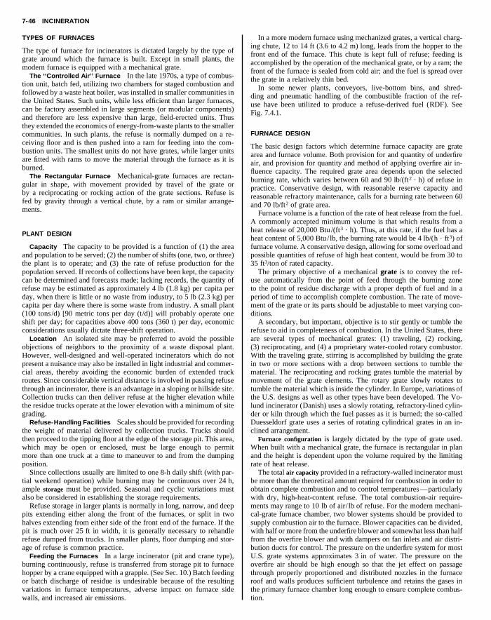
7-46 INCINERATION
TYPES OF FURNACES
The type of furnace for incinerators is dictated largely by the type ofgrate around which the furnace is built. Except in small plants, themodern furnace is equipped with a mechanical grate.
The ‘‘Controlled Air’’ Furnace In the late 1970s, a type of combus-tion unit, batch fed, utilizing two chambers for staged combustion andfollowed by a waste heat boiler, was installed in smaller communities inthe United States. Such units, while less efficient than larger furnaces,
In a more modern furnace using mechanized grates, a vertical charg-ing chute, 12 to 14 ft (3.6 to 4.2 m) long, leads from the hopper to thefront end of the furnace. This chute is kept full of refuse; feeding isaccomplished by the operation of the mechanical grate, or by a ram; thefront of the furnace is sealed from cold air; and the fuel is spread overthe grate in a relatively thin bed.
In some newer plants, conveyors, live-bottom bins, and shred-ding and pneumatic handling of the combustible fraction of the ref-use have been utilized to produce a refuse-derived fuel (RDF). SeeF
F
Taaflbpra
Ahhfp3
utpmd
ra(WimmttldDc
War
bowmcswfbUotrtt
Copyright (C) 1999 by The McGraw-Hill Companies, Inc. All rights reserved. Use ofthis product is subject to the terms of its License Agreement. Click here to view.
can be factory assembled in large segments (or modular components)and therefore are less expensive than large, field-erected units. Thusthey extended the economics of energy-from-waste plants to the smallercommunities. In such plants, the refuse is normally dumped on a re-ceiving floor and is then pushed into a ram for feeding into the com-bustion units. The smallest units do not have grates, while larger unitsare fitted with rams to move the material through the furnace as it isburned.
The Rectangular Furnace Mechanical-grate furnaces are rectan-gular in shape, with movement provided by travel of the grate orby a reciprocating or rocking action of the grate sections. Refuse isfed by gravity through a vertical chute, by a ram or similar arrange-ments.
PLANT DESIGN
Capacity The capacity to be provided is a function of (1) the areaand population to be served; (2) the number of shifts (one, two, or three)the plant is to operate; and (3) the rate of refuse production for thepopulation served. If records of collections have been kept, the capacitycan be determined and forecasts made; lacking records, the quantity ofrefuse may be estimated as approximately 4 lb (1.8 kg) per capita perday, when there is little or no waste from industry, to 5 lb (2.3 kg) percapita per day where there is some waste from industry. A small plant(100 tons/d) [90 metric tons per day (t/d)] will probably operate oneshift per day; for capacities above 400 tons (360 t) per day, economicconsiderations usually dictate three-shift operation.
Location An isolated site may be preferred to avoid the possibleobjections of neighbors to the proximity of a waste disposal plant.However, well-designed and well-operated incinerators which do notpresent a nuisance may also be installed in light industrial and commer-cial areas, thereby avoiding the economic burden of extended truckroutes. Since considerable vertical distance is involved in passing refusethrough an incinerator, there is an advantage in a sloping or hillside site.Collection trucks can then deliver refuse at the higher elevation whilethe residue trucks operate at the lower elevation with a minimum of sitegrading.
Refuse-Handling Facilities Scales should be provided for recordingthe weight of material delivered by collection trucks. Trucks shouldthen proceed to the tipping floor at the edge of the storage pit. This area,which may be open or enclosed, must be large enough to permitmore than one truck at a time to maneuver to and from the dumpingposition.
Since collections usually are limited to one 8-h daily shift (with par-tial weekend operation) while burning may be continuous over 24 h,ample storage must be provided. Seasonal and cyclic variations mustalso be considered in establishing the storage requirements.
Refuse storage in larger plants is normally in long, narrow, and deeppits extending either along the front of the furnaces, or split in twohalves extending from either side of the front end of the furnace. If thepit is much over 25 ft in width, it is generally necessary to rehandlerefuse dumped from trucks. In smaller plants, floor dumping and stor-age of refuse is common practice.
Feeding the Furnaces In a large incinerator (pit and crane type),burning continuously, refuse is transferred from storage pit to furnacehopper by a crane equipped with a grapple. (See Sec. 10.) Batch feedingor batch discharge of residue is undesirable because of the resultingvariations in furnace temperatures, adverse impact on furnace sidewalls, and increased air emissions.
ig. 7.4.1.
URNACE DESIGN
he basic design factors which determine furnace capacity are graterea and furnace volume. Both provision for and quantity of underfireir, and provision for quantity and method of applying overfire air in-uence capacity. The required grate area depends upon the selectedurning rate, which varies between 60 and 90 lb/(ft2 ? h) of refuse inractice. Conservative design, with reasonable reserve capacity andeasonable refractory maintenance, calls for a burning rate between 60nd 70 lb/ft2 of grate area.
Furnace volume is a function of the rate of heat release from the fuel.commonly accepted minimum volume is that which results from a
eat release of 20,000 Btu/(ft3 ? h). Thus, at this rate, if the fuel has aeat content of 5,000 Btu/ lb, the burning rate would be 4 lb/(h ? ft3) ofurnace volume. A conservative design, allowing for some overload andossible quantities of refuse of high heat content, would be from 30 to5 ft3/ton of rated capacity.
The primary objective of a mechanical grate is to convey the ref-se automatically from the point of feed through the burning zoneo the point of residue discharge with a proper depth of fuel and in aeriod of time to accomplish complete combustion. The rate of move-ent of the grate or its parts should be adjustable to meet varying con-
itions.A secondary, but important, objective is to stir gently or tumble the
efuse to aid in completeness of combustion. In the United States, therere several types of mechanical grates: (1) traveling, (2) rocking,3) reciprocating, and (4) a proprietary water-cooled rotary combustor.
ith the traveling grate, stirring is accomplished by building the graten two or more sections with a drop between sections to tumble theaterial. The reciprocating and rocking grates tumble the material byovement of the grate elements. The rotary grate slowly rotates to
umble the material which is inside the cylinder. In Europe, variations ofhe U.S. designs as well as other types have been developed. The Vo-und incinerator (Danish) uses a slowly rotating, refractory-lined cylin-er or kiln through which the fuel passes as it is burned; the so-calleduesseldorf grate uses a series of rotating cylindrical grates in an in-
lined arrangement.Furnace configuration is largely dictated by the type of grate used.hen built with a mechanical grate, the furnace is rectangular in plan
nd the height is dependent upon the volume required by the limitingate of heat release.
The total air capacity provided in a refractory-walled incinerator muste more than the theoretical amount required for combustion in order tobtain complete combustion and to control temperatures—particularlyith dry, high-heat-content refuse. The total combustion-air require-ents may range to 10 lb of air/ lb of refuse. For the modern mechani-
al-grate furnace chamber, two blower systems should be provided toupply combustion air to the furnace. Blower capacities can be divided,ith half or more from the underfire blower and somewhat less than half
rom the overfire blower and with dampers on fan inlets and air distri-ution ducts for control. The pressure on the underfire system for most.S. grate systems approximates 3 in of water. The pressure on theverfire air should be high enough so that the jet effect on passagehrough properly proportioned and distributed nozzles in the furnaceoof and walls produces sufficient turbulence and retains the gases inhe primary furnace chamber long enough to ensure complete combus-ion.

FURNACE DESIGN 7-47
Flail millMagnet
Hammermillshredder
Trommel screen
Air classifier
Recyclablematerial
Refuse-derivedfuel
Small-sizedmaterial, 2 inch Medium-sized
material, 8 inch
Oversizedmaterial. 8 inch
Ferrousmetals
Small dense materialto landfill
Small lightmaterial
Fig. 7.4.1 Process diagram for a typical RDF system. (Roy F. Weston, Inc.)
Heat Recovery Perhaps the most potentially attractive form of re-covery, or extraction, of resources from municipal solid wastes is re-covery of energy from the incineration process.
Several options exist when one is considering recovery of energyfrom incineration. These options include mass burning in a refractory-
walled furnace with a waste-heat boiler inserted in the flue downstream;mass burning in a water-walled furnace with the convection surfaceimmediately downstream; and refuse preprocessing and separation ofthe combustible fraction with combustion taking place in a utility-typeboiler partially in suspension and partially on a grate. This latter option
Table 7.4.1 Energy-from-Waste Plants Larger than 300 tons/day Commissioned 1990–1995
rt-ear
111104
Copyright (C) 1999 by The McGraw-Hill Companies, Inc. All rights reserved. Use ofthis product is subject to the terms of its License Agreement. Click here to view.
Plant size StaPlant location (tons/d) y
Broward County, FL, north 2,250 199Broward County, FL, south 2,250 199Camden, NJ 1,050 199Chester, PA 2,688 199Essex County, NJ 2,250 199Fort Myers, FL (Lee County) 1,200 199
Gloucester County, NJ 575 1990Honolulu, HI 2,165 1990Hudson Falls, NY 400 1992Huntington, NY 750 1991Huntsville, AL 690 1990Kent County, MI 625 1990Lake County, FL 528 1991Lancaster County, PA 1,200 1991Long Beach, CA 1,380 1990Lorton, VA (Fairfax County) 3,000 1990Montgomery County, PA 1,200 1991Pasco County, FL 1,050 1991Rochester, MA 2,700 1988/1Southeast CT (Preston, CT) 600 1992Spokane, WA 800 1991Union County, NJ 1,440 1994Wallingford, CT 420 1990upType Energy sold
Mass burn water wall ElectricityMass burn water wall ElectricityMass burn water wall ElectricityRotary kiln water wall ElectricityMass burn water wall ElectricityMass burn water wall Electricity
Mass burn water wall ElectricityRDF water wall ElectricityMass burn water wall ElectricityMass burn water wall ElectricityMass burn water wall SteamMass burn water wall Electricity/steamMass burn water wall ElectricityMass burn water wall ElectricityMass burn water wall ElectricityMass burn water wall ElectricityMass burn water wall ElectricityMass burn water wall Electricity993 RDF water wall ElectricityMass burn water wall ElectricityMass burn water wall ElectricityMass burn water wall ElectricityMass burn water wall Electricity/steam

7-48 INCINERATION
is generally termed combustion of a refuse-derived fuel. A list of water-wall and RDF plants in North America in start-up or operation as of theend of 1994 extracting energy from combustion of municipal-typewaste is shown in Table 7.4.1. This list excludes plants built for devel-opmental or experimental purposes and plants that utilize specializedindustrial wastes.
Figure 7.4.2 illustrates a plant with heat recovery, while Fig. 7.4.3shows a cross section through a typical RDF facility.
In considering the above options, one should taken into account the
Other factors to consider in selection and design of heat-recoveryfacilities include efficiency of boiler facilities, furnace-chamber design,and combustion air supply. While in older plants with waste-heat boil-ers installed in downstream flues, steam production averaged 1.5 to 1.8lb/ lb of refuse, in newer water-walled furnaces and suspension-firedunits, steam production is of the order of 3.0 lb/ lb of refuse. The lowerefficiency in waste-heat boiler units is due to higher heat losses in theplant stack effluent, in turn caused by higher excess air levels requiredto control combustion temperatures properly in the refractory-lined pri-
Copyright (C) 1999 by The McGraw-Hill Companies, Inc. All rights reserved. Use ofthis product is subject to the terms of its License Agreement. Click here to view.
overall energy balance in the various systems. These systems can begrouped under the following general categories: burning as-receivedrefuse; burning mechanically processed refuse; burning thermochemi-cally processed refuse; and burning biochemically processed refuse. Inall the processing systems, less heat will be available for use than therewas prior to processing.
The tabulation below from published data regarding the production ofa fuel gas from refuse will partially illustrate the net energy loss inconverting the available energy to another form:
Percent Percent by Percent ofComposition by volume weight total carbon
CO 47 62.1 70H2 33 3.1CO2 14 29.1 21CH4 4 3.0 6C2H2 1 1.4 3N2 1 1.3
Note that 21 percent of the carbon is in CO2 which will not burn,while 70 percent of the carbon is in CO where 30 percent of the elemen-tal energy in carbon is no longer available. While this heat is not wasted,it is lost energy not available to do further work.
A tabulation of energy losses and total net available energy, based oninformation published in 1974–1975 for refuse with an initial heat con-tent of 4,400 Btu/ lb, is given in Table 7.4.2.
Of the 4,400 Btu/ lb in the refuse as received, the tabulated dataindicate the useful energy that may be made available through combus-tion. While the data are not absolute, the relative magnitudes are mean-ingful, provided similar degrees of design efficiency and sophisticationof control are used for each process.
Superheater
Tipping floor
Refuse pit Furnace/
Grates
Overheadcrane
Charginghopper
Fig. 7.4.2 Typical cross section of a mass burn facility. (Roy F. Weston, Inc.)
mary furnace enclosure.In most water-walled furnaces and furnaces in which shredded com-
bustible refuse fractions are burned, the usual configuration is a tallprimary chamber with the gases passing out the top and into the convec-tion boiler surface after completion of combustion. It has been founddesirable in mass-burning water-wall plants to coat a substantial heightof the primary combustion chamber (where boiler-tube metal tempera-tures will exceed 500°F) with a refractory material and to limit averagegas velocities to under 15 ft /s. Gas velocity entering the boiler convec-tion bank should be less than 30 ft /s. Water-table studies have beenfound to be very useful in checking combinations of furnace configura-tions and introduction of combustion air.
In mass burning, combustion air is usually supplied from both underand over the grate. This is not necessarily the case when burning pre-pared refuse. In a water-wall mass-burning type of furnace, overfire airis utilized to enhance turbulence and mixing of combustion gases withthe combustion air, and for completion of combustion. Accordingly,this air is best introduced through numerous relatively small (11⁄2- to3-in-diameter) nozzles, at pressures of 20 in of water and higher. Ide-ally, provision should be made for the introduction of the overfire air atseveral different elevations in the furnace.
As this nation’s energy needs become more critical in the future, thisreadily available source of energy should be tapped more frequently.The technology is available now for successful application of thesetechniques if provision is made for adequate funding and properlytrained operating staffs.
Flues and chambers beyond the furnace convey gases to the stack andhouse facilities for removal of fly ash and other pollutants. The draft foran incinerator furnace may be provided by a stack of adequate diameterand height or by an induced-draft fan. (See Secs. 4 and 14.) Most mod-ern plants include heat recovery equipment and extensive air pollution
Evaporator
Economizer
boilerScrubber Baghouse Stack

COMBUSTION CALCULATIONS 7-49
RDF storagebuilding
RDF processingsystem
Superheater
Furnace/boilerScrubber Baghouse Stack
Evaporator
Economizer
Air preheater
Tipping floor
RDF returnfrom boiler
RDF to boiler
RDF to storage
Fig. 7.4.3 Typical cross section of an RDF facility. (Roy F. Weston, Inc.)
control equipment. In these plants, draft losses are so high that an in-duced-draft fan is required.
Air Pollution Control The federal new source emission standard forair pollution control at new or enlarged municipal sized incinerators is0.015 grain per dry standard cubic foot (gr/DSCF) (34 mg/DSCM)corrected to 7 percent O2 . (This is approximately 0.03 lb/1,000 lbof flue gas corrected to 50 percent excess air.) Some jurisdictionshave promulgated emission requirements lower than the federal stan-dards. Designers of modern plants will also have to include facilities to
truck through a bottom gate. The residue may also be dischargedthrough a chute into a conveyor trough filled with water for quenchingand then carried by flight conveyor to an elevated storage hopper fortruck delivery. Usually there are two conveyor troughs, so arranged thatthe residue can be discharged to either, one trough being used at a time.A European system uses a ram discharger submerged in a water-filledcontainer.
The lower end of the discharge chute leading to the trough is sub-
va
los
mb
332
Copyright (C) 1999 by The McGraw-Hill Companies, Inc. All rights reserved. Use ofthis product is subject to the terms of its License Agreement. Click here to view.
reduce acid gas emissions and, at some plants, NOx and mercury emis-sions.
To meet current emission requirements, two basic techniques havebeen utilized on incinerators: electrostatic precipitation and fabric filterspreceded by lime addition in a slurry, so-called ‘‘dry scrubbing.’’ Elec-trostatic precipitation has performed reliably and has given predictableemission test results. The fabric filter/dry scrubber air pollution controlsystem is considered by many to represent the most efficient combina-tion of pollution control systems currently available for particulates andacid gases. Nonselective catalytic reduction using ammonia has beenapplied at some plants for NOx control, while limited experiencehas been gained in the use of activated carbon for control of mercuryemissions. Good combustion control is used to limit emission of or-ganics.
Residue Discharge and Disposal The residue from refuse burningconsists of relatively fine, light ash mixed with items such as burned tincans, partly melted glass, and pieces of metal. Discharge from furnacesmay be through manually operated dump grates or from mechanicallyoperated grates to a hopper, where it is quenched and delivered to a
Table 7.4.2 Energy Losses and Total Net AHeat Content of 4,400 Btu/lb, 1974–1975
Energy
Process Processing Co
As received 1Dry shredding 18Wet shredding 35Pyrolysis, oil 62
Pyrolysis, gas 32 2Pyrolysis with oxygen 37 1Anaerobic digestion 72merged in a water seal to prevent entrance of cold air to the furnace. Indesign of the conveyor mechanism, the proportions should be largebecause of the nature of the material handled, and the metal used shouldbe selected to withstand severe abrasive service. Final disposal of theresidue is by dumping at a suitable location, which for modern plantsusually means a monofill. Volume required for disposal is 5 to 15 per-cent of that required for dumping raw refuse.
Miscellaneous Facilities Good working environment and reason-able comfort for the staff should be provided.
COMBUSTION CALCULATIONS
Among the factors directly affecting design are moisture and combustiblecontent of refuse as received, heat released by combustion, temperaturecontrol, and water requirements. The design of furnaces, chambers,flues, and other plant elements should be based on characteristics whichresult in large sizes. Controls should provide satisfactory operation forloads below the maximum. The computations which follow are forrelatively high heat releases.
The prime factors in heat calculations are the moisture and combusti-
ilable Energy for Refuse with Initial
s, %
ustion TotalTotal net
available energy Btu/ lb
9 40 2,6400 48 2,2881 56 1,9369 71 1,276
5 57 1,8925 52 2,1126 78 968
7-50 INCINERATION
ble content of the refuse and heat released by burning the combustibleportion of the refuse. The moisture content may vary from 20 to 50percent by weight, and the combustible content may range from 25 to 70percent. The combustible portion is composed largely of cellulose andsimilar materials, mixed with proteins, fats, oils, waxes, rubber, andplastics. The heat released by burning cellulose is approximately 8,000Btu/ lb, while that released by the plastics, fats, oils, etc., is approxi-mately 17,000 Btu/ lb. If cellulose, plastics, oil, and fat exist in therefuse in the ratio of 5 : 1, the heat content of the combustible matter will
combustion, e.g., 140 percent of theoretical so that, in the examplecited:
Total air 5 1.8 3 374.4 5 674 lb/100 lb refuse
To summarize the quantities for a computation of furnace tempera-ture, a materials balance is given in Table 7.4.4 equating the input to thefurnace and output for 100 lb of refuse. In this tabulation, allowance is
3
Copyright (C) 1999 by The McGraw-Hill Companies, Inc. All rights reserved. Use ofthis product is subject to the terms of its License Agreement. Click here to view.
be 9,500 Btu/ lb. The heat content per pound of refuse as received, forvarying proportions of moisture and noncombustibles, is given in Table7.4.3 and Fig. 7.4.4
Determination of the air requirement is illustrated by computationwith refuse of 5,000 Btu/ lb heat content where (from Fig. 7.4.4) thecomposition is: combustible, 58.6 percent; noncombustible, 19.0 per-cent.
Carbon and hydrogen are the essential fuel elements in combustion ofrefuse; sulfur and other elements which oxidize during combustion arepresent in trace amounts and do not contribute significantly to the heatof combustion. Carbon and hydrogen content can be determined from acomplete analysis of the refuse, but such an analysis is of questionablevalue because of the variable character of refuse and the difficulty ofobtaining representative samples. For the purpose of this computation, atypical analysis is used in which the total carbon is 28 lb and the hydro-gen 1.5 lb/100 lb of refuse. It is probable that 1 to 3 lb of combustiblematerial per 100 lb of refuse will escape unburned with the residue. Forthe sake of clarity in the illustrated computations, complete combustionis assumed.
Oxygen requirements and products of combustion can be determinedfrom the reactions as follows:
Cellulose C6H10O5 1 6O2 : 6CO2 1 5H2OAtomic wt: 72 1 10 1 80 1 192 5 264 1 90
162 1 192 5 264 1 90Ratios:
Referred to carbon: 1 1 0.14 1 1.11 1 2.667 5 3.667 1 1.25Referred to cellulose: 1 1 1.185 5 1.63 1 0.555
Carbon C 1 O2 : CO2
Atomic wt: 12 1 32 5 44Ratio: 1 1 2.667 5 3.667
Hydrogen 2H2 1 O2 : 2H2OAtomic wt: 4 1 32 5 36Ratio: 1 1 8 5 9
The theoretical air required per 100 lb of refuse follows from thesefigures where air is considered to contain 23.15 percent oxygen.
Air required 5 28 3 2.667/0.2315 1 1.53 8/0.2315 5 374.4 lb/100 lb refuse
For incineration, furnace temperature must be controlled to minimizerefractory maintenance. With no other provision for heat absorption, itis necessary to introduce excess air well beyond the needs for complete
Table 7.4.3 Heat Content of Refuse, as Received
N
10 15
Comb., Heat Comb., HMoisture, % % content* % con
50 40 3,800 35 3,
40 50 4,750 45 4,230 60 5,700 55 5,220 70 6,650 65 6,1* Btu/ lb.
20 30
10% noncom
bustible
15% noncom
bustible
20% noncom
bustible
25% noncom
bustible
Percent moisture
Btu
per
lb o
f ref
use
Per
cent
com
bust
ible
mat
eria
l
40 50
7,000
6,000
5,000
4,000
3,000
2,000
70
60
50
40
30
Fig. 7.4.4 Moisture–heat content relation with 9,500 Btu/ lb combustiblematerial.
made for moisture in the air at a commonly accepted rate of 0.0132 lb/ lbof dry air. Some residue quench water will be evaporated, and the mois-ture added to the flue gases is estimated at 5 lb for each 100 lb of refuseburned. Since the assumed analyses are not precise, an exact balance isnot obtained, but the indicated computations are sufficiently accuratefor incinerator design.
oncombustible, %
20 25
eat Comb., Heat Comb., Heattent* % content* % content*
25 30 2,850 25 2,375
75 40 3,800 35 3,32525 50 4,750 45 4,27575 60 5,700 55 5,225
RECOVERY 7-51
Table 7.4.4 Materials Balance for Furnace lb/100 lb of Refuse
Input:Refuse
Combustible materialCellulose 43.75Plastics, oils, fats, etc. 8.75 52.5
Moisture 25.0Noncombustible 22.5 100.0
In Table 7.4.4, total air is broken down into oxygen and nitrogen onthe basis that 23.15 percent of the air is oxygen. To compute the air inthe ‘‘output,’’ or flue gas, the nitrogen is the same as the ‘‘input.’’Oxygen is diminished by the amount consumed in combustion. Sincecarbon and hydrogen unite with oxygen during combustion, the oxygenconsumed per 100 lb refuse is:
For carbon, 28 3 2.667 5 74.68 lbFor hydrogen, 1.5 3 8 5 12.00 lb
Copyright (C) 1999 by The McGraw-Hill Companies, Inc. All rights reserved. Use ofthis product is subject to the terms of its License Agreement. Click here to view.
Total air, at 140% excess airOxygen 156.0Nitrogen 517.9 673.9
Moisture in air 8.9Residue quench water 5.0
Total 787.8Output:
CO2 (28 3 3.667) 102.7Air
Oxygen (156-87) 69.0Nitrogen 517.9 586.9
MoistureIn refuse 25.0From burning cellulose 24.3From burning hydrogen 13.5In air 8.9In residue quench water 5.0 76.7
Furnace gas subtotal 766.3Noncombustible material 22.5Unaccounted for 2 1.0
Total 787.8
600
Temperature, °F
Ent
halp
y ab
ove
80°F
, Btu
/lb
KJ/
kg
600
550
500
450
400
350
300
250
200
150
100
1200
800 1000 1200 1400
1200
Temperature, °F1400 1600 1800 2000
900
600
300
Moisture in
% weight o
f total flu
e gas
20
20
10
10
0
0
Fig. 7.4.5 Enthalpy of flue gas above 80°F.
Total 86.68, say 87 lb
The moisture from burning cellulose and hydrogen is: for cellulose,0.555 3 43.75 5 29.3 lb; for hydrogen, 9 3 1.5 5 13.5 lb.
Abiabatic flame temperature is the maximum theoretical temperaturethat can be reached by the products of combustion of a specific fuel-aircombination. To calculate this temperature, the total heat input in thefuel is adjusted to subtract the heat input required to vaporize moisturein the fuel, moisture produced in combustion of cellulose and hydrogen,and the residue quench water that is vaporized. A loss is assumed toaccount for incomplete combustion and other small losses. The remain-ing heat energy is the sensible heat available in the furnace gas. It can becalculated per 100 lb of refuse from the data of Table 7.4.4 and theenthalpy data of Fig. 7.4.5 as follows:
Input, 100 lb 3 5,000 Btu/ lb 500,000 BtuLosses:
Heat of vaporization deductionMoistureIn refuse 25.0From burning cellulose 24.3From burning hydrogen 13.5From reside quench 5.0
67.867.8 3 1,050 Btu/ lb 71,900
Assumed loss due to incompletecombustion and other losses 2% 10,000
Total deduction 2 81,190Sensible heat available in furnace gas 418,810 BtuEnthalpy of gas, 418,810 Btu 4 766.3 lb 547 Btu/ lb% Moisture in furnace gas
Moisture vaporized 67.8Moisture in air 8.9
76.776.74 766.3 5 10.0%
Temperature of furnace gas at 547Btu/ lb and 10.0% moisture fromFig. 7.4.5
1,950°F
RECOVERY
Many modern waste-to-energy (WTE) plants incorporate waste pro-cessing/materials recovery facilities. Such facilities are a natural ad-junct at plants producing RDF. Relatively active stable markets havedeveloped for newsprint, glass, metals, and certain specific plastics.Recent surveys of waste composition indicate that after recycling, paperand noncombustibles have decreased slightly while high-heat-valueplastics have increased significantly as a percentage of municipal solidwaste going to disposal. The impact of these changes in waste composi-tion has been to increase slightly the heat content of waste available forprocessing in WTE plants and to remove some of the more troublesomematerials from a materials handling standpoint.
Fly ash has been used to a limited extent as a concrete additive and asa road base. Incinerator residue has been used for land reclamation inlow areas and, in some cases, as a road-base material. Generally, beforesuch use, the fly ash and residue must be tested to ensure that theycannot be classified as hazardous waste.

7.5 ELECTRIC FURNACES AND OVENSby George J. Roddam
REFERENCES: Robiette, ‘‘Electric Melting and Smelting Practice,’’ Griffin.Campbell, ‘‘High-Temperature Technology,’’ Wiley. ‘‘Electric-Furnace SteelProceedings,’’ Annual, AIME. Paschkis, ‘‘Industrial Electric Furnaces and Appli-ances,’’ Interscience. Stansel, ‘‘Induction Heating,’’ McGraw-Hill. Ess, TheModern Arc Furnace, Iron Steel Eng.,
CLASSIFICATION AND SERVICE
The furnaces and ovens addressesmall and medium-size units use
process. This freedom is often a primary reason for the use of electricheat.
3. The maximum temperature is limited only by the nature of thematerial of the charge.
e the design of all electric heatingrmal processes for the productionany other way.
Fig. 7.5.1hearth resisto
7-52
Copyright (C) 1999 by The McGraw-Hill Companies, Inc. All rights reserved. Use ofthis product is subject to the terms of its License Agreement. Click here to view.
Feb. 1944.
d in this section generally are thosed in general foundry practice, heat
The first two characteristics underliapparatus. The third is utilized in theof certain materials not obtainable in
RESISTOR FURNACES
treating, and associated processes. The larger units are generally usedfor melting large quantities of metal as part of specific production pro-cesses such as the production of high-purity alloy steels, processingbatches of processed parts receiving vitreous enamel, annealing glass,and so on.In resistor furnaces and ovens, heat is developed by the passage ofcurrent through distributed resistors (heating units) mounted apart fromthe charge. Alternating current of a standard power frequency is used.The furnace service is for heat applications to solids such as heat treat-ment of metals, annealing glass, and firing of vitreous enamel. Ovenservice is limited to drying and baking processes usually below 500°F(260°C).
In induction heaters heat is developed by currents induced in thecharge. The service is heating metals to temperatures below the meltingpoints.
In induction furnaces heat is developed by currents induced in thecharge. The service is melting metals and alloys.
In arc furnaces heat is developed by an arc, or arcs, drawn either tothe charge or above the charge. Direct-arc furnaces are those in whichthe arcs are drawn to the charge itself. In indirect-arc furnaces the arc isdrawn between the electrodes and above the charge. A standard powerfrequency is used in either case. Direct-current (dc) electric power is analternative source of energy. The general service is melting and refiningmetals and alloys. The ladle arc furnace is used particularly when acharge of metal is to be processed primarily to refine its chemistry.
In resistance furnaces of the submerged-arc type, heat is developed bythe passage of current from electrode to electrode through the charge.The manufacture of basic products, such as ferroalloys, graphite, cal-cium carbide, and silicon carbide, is the general service. Alternatingcurrent at a standard power frequency is used. An exception is the use ofdirect current where the product is obtained by electrolytic action in amolten bath, e.g., in the production of aluminum.
The characteristics of electric heat are:1. Precision of the control of the development of heat and of its
distribution.2. The heat development is independent of the nature of the gases
surrounding the charge. This atmosphere can be selected at will withreference to the nature of the charge and the chemistry of the heat
Heating chamber with sidewall andrs.
Resistor furnaces may be either the batch or the continuous type. Batchfurnaces include box furnaces, elevator furnaces, car-bottom furnaces,and bell furnaces. Continuous furnaces include belt-conveyor furnaces,chain-conveyor furnaces, rotary-hearth furnaces, and roller-hearth fur-naces.
Standard resistor furnaces are designed to operate at temperatureswithin the range 1,000 to 2,000°F (550 to 1,200°C). For higher heatingchamber temperatures, see Resistors, later in this section.
The heating chamber of a standard furnace is an enclosure with arefractory lining, a surrounding layer of heat insulation, and an outercasing of steel plate, or for large furnaces an outer layer of brick or tile,as indicated by Figs. 7.5.1 and 7.5.2. The hearth of a batch furnace oftenis constructed of a heat-resisting alloy, made in sections to preventwarping. In some continuous furnaces the conveyor forms the hearth; inothers a separate hearth is required.
Insulating firebrick—a semirefractory material—is commonly usedfor the inner lining of the heating chamber. This material has thermaland physical properties intermediate between those of fire-clay brickand heat-insulating materials. A lining of this kind has less heat-storagecapacity than a fire-clay brick lining, and its use accordingly decreasesthe time periods of heating and cooling the chamber and also decreasesthe stored-heat loss for a given cycle of operation. Other advantages areits high heat-insulating value and light weight.
The maximum temperature of the inner face of the layer of heatinsulation determines the character of material required for the insula-tion. Practically all resistor furnaces have insulation made of diatomite.Composite wall structures with a 41⁄2-in (11-cm) semirefractory liningand a 9- to 13-in (23- to 33-cm) layer of heat insulation represent gen-eral practice for standard furnaces. (See also Sec. 4.3.)
Atmospheres A mixture of air and the gases evolved from thecharge constitutes a natural atmosphere in the heating chamber of aresistor furnace. The composition of such an atmosphere in a batchfurnace is variable during a heating cycle. A natural atmosphere in theheating chamber of a continuous furnace is mainly air. Natural atmo-spheres are used where the extent of the action of oxygen on the chargeduring the heating cycle is not objectionable and for processes wherethat chemical action is desired. (See also Sec. 7.3.)
Fig. 7.5.2 Heating chamber with roof andhearth resistors.

RESISTOR FURNACES 7-53
The basis of an artificial atmosphere is the exclusion of oxygen (air)from the heating chamber by the substitution of some other gas ormixture of gases. This gas or mixture of gases is selected with referenceto the chemical activity of that atmosphere on the charge at the tempera-ture of the heat application. A definite chemical action may be desired,for example, the reduction of any metallic oxide present on the charge,or it may be required that the artificial atmosphere to be chemicallyinactive. Thus artificial atmospheres are divided into (1) active or pro-cess atmospheres and (2) inactive or protective atmospheres. The term
bon dioxide-carbon system (F) the volume ratio of the two gases atequilibrium with the carbon in low- and medium-carbon steel at a giventemperature is somewhat greater than the value shown by curve F; forhigh-carbon steels the equilibrium volume-ratios approach the values ofcurve F.
In the case of the hydrogen-iron oxide reaction, curve A, the watervapor content of the mixture of gases at equilibrium decreases withdecrease of temperature. Hence if a steel is to be cooled in a controlledatmosphere of this kind, the permissible water vapor content of the
Copyright (C) 1999 by The McGraw-Hill Companies, Inc. All rights reserved. Use ofthis product is subject to the terms of its License Agreement. Click here to view.
‘‘controlled’’ atmosphere refers generally to a protective atmosphere,but it also includes artificial atmospheres of some degree of chemicalactivity. An example of a process atmosphere is the use of a hydrocar-bon gas to carburize steel. Examples of controlled atmospheres are: thebright annealing of metals, the prevention of decarburization of steelduring a heat application, the use of a reducing gas (hydrogen or carbonmonoxide) in a copper brazing furnace, etc. In this last example thereducing gas serves to clean the faces of the joint to be made (byremoval of any oxide present) and to maintain that cleanliness duringthe operation. The primary gases for controlled atmospheres are hydro-gen and carbon monoxide and nitrogen.
The main uses of controlled atmospheres are (1) the prevention of theformation of oxides on the material of the charge, or conversely thereduction of any oxides present, and (2) the prevention of a change inthe carbon content of a steel undergoing a heat treatment. Each of theseuses denotes a chemical system in which the reactions are reversible.
The chemical systems relating to metallic oxides are:
A: Oxide 1 hydrogen N metal 1 water vaporB: Oxide 1 carbon monoxide N metal 1 carbon dioxide
The chemical systems relating to carbon in steel are
E: Methane N hydrogen 1 carbonF: Carbon monoxide N carbon dioxide 1 carbon
In artificial atmospheres the volume ratio of the two gases in theheating chamber should be so maintained as to correspond to the desireddirection of the chemical activity of the system, or, if no chemical actionis desired, to maintain that volume ratio at (or near) its equilibriumvalue for the temperature of the heat application. The equilibrium vol-ume ratios for each of the four chemical systems A, B, E, and F forcarbon steel over the usual range of temperature of heat-treatment pro-cesses and for atmospheric pressure are shown in Fig. 7.5.3. There islittle tendency toward a change in the carbon content of a steel belowthe critical range. Oxidation is active down to about 1,100°F (650°C).
Curves E and F of Fig. 7.5.3 show the volume ratios of systems Eand F for equilibriums with graphite. The equilibrium volume ratios ofthese two chemical systems for carbon in solid solution in steel (austen-ite) depend in each case on the carbon content of the steel. For themethane-hydrogen-carbon system (E) the volume ratio of the two gasesat equilibrium with carbon in an unsaturated steel at a given temperatureis less than the value shown by curve E. For the carbon monoxide-car-
Fig. 7.5.3 Equilibrium volume ratios of chemical systems A, B, E, and F forsteel. C 5 carburizing condition; O 5 oxidizing; D 5 decarburizing; R 5 reduc-ing.
controlled atmosphere is dictated by the lowest temperature of the oper-ation. The reverse is true of the carbon monoxide–iron oxide reaction,curve B. Thus if at a given temperature the carbon dioxide content of themixture of carbon monoxide and carbon dioxide is less than the volumefor equilibrium at that temperature it will be less than the volume forequilibrium at any lower temperatures and the steel can be cooled in thatatmosphere without oxidation.
In the use of mixtures of the gases of the chemical systems noted toform controlled atmospheres for the heat treatment of steel, the interac-tions of the gases at elevated temperatures must be controlled by re-moval of all or nearly all the carbon dioxide and water vapor from theheating chamber.
The available data concerning controlled atmospheres for the protec-tion of alloy steels during heat-treatment processes indicate that thetechnique for alloy steels is much the same as for carbon steels; i.e., acontrolled atmosphere suitable for a carbon steel would, in general, besuitable for an alloy steel of the same carbon content.
In the heat treatment of nonferrous metals and alloys the use of eitherchemical system A or B requires for each oxide a knowledge of theequilibrium volume ratios of the chemical system used over the range ofthe operating temperature. Individual problems may arise. For example,copper can be bright-annealed in an atmosphere of dry steam—an inac-tive gas for this application—but the resultant staining of the copperduring cooling may be objectionable. Copper usually contains a smallpercentage of oxide, and when annealing such copper in an atmospherecontaining a reducing gas the temperature of the metal must be keptbelow about 750°F (420°C); otherwise the oxide will be reduced and thecopper made brittle.
The foregoing discussion of atmosphere in heating chambers is in-tended to indicate the principles involved in the use of gases at elevatedtemperatures. The terms oxidation, reduction, carburization, and decar-burization refer here to the chemical condition of a particular atmo-sphere and not to the extent of its effect on a charge. In all cases theconcentration of the active gas or gases, time, temperature, in case ofsteel the carbon content and the gas pressure, and the catalytic action ofhot surfaces within the chamber are important factors in the result ob-tained.
Bath Heating Heating for local hardening of edge tools is the mostgeneral service. The lead-bath furnace has a working temperature rangeof 650 to 1,700°F (360 to 950°C). The salt-bath furnace can be adaptedto working-temperature ranges within a total range of 300 to 2,350°F(170 to 1,300°C) by the selection of suitable mixture of salts. The twosalt baths most generally used are cyanide mixtures and chloride mix-tures. The rate of heating by immersion is much faster than obtained byradiation. The rate of heat transfer in a salt bath is about one-half that inthe lead bath. An additional use of the salt bath is for cyaniding, in effecta process atmosphere.
Resistors The resistor of a standard furnace is a sinuous windingmounted on the inner surfaces of the heating chamber as shown in Figs.7.5.1 and 7.5.2. The resistor winding covers practically the entire sur-face of the space chosen. Resistors are applied on the basis of 2 to3 kW/ft2 (20 to 30 kW/m2) of wall surface in general practice. The basisof resistor location is radiation to all surfaces of the charge. Hence, theheight and width dimensions of the heating chamber indicate the choicebetween sidewall and roof resistors. In some cases both locations areused. Uniform distribution of heat flow to the charge is obtained by adesigned distribution of the surfaces of the resistors supplemented byreradiation from the inner surfaces of the chamber.
Resistors for the majority of standard furnaces are made of 80 Ni,

7-54 ELECTRIC FURNACES AND OVENS
20 Cr alloy. A nickel-chromium-iron alloy is used in some furnaces foroperation only over the lower portion of the furnace temperature range.Both ribbon and cast shapes are in use. The effort in each case is toobtain the maximum surface area per unit length of resistor and at thesame time retain sufficient mechanical strength in the resistor winding.
The 80 Ni, 20 Cr alloy is self-protecting against oxidation, but thisprotection decreases with rise of temperature. The operating tempera-ture of a resistor should be no higher than is needed in each case andshould always be at a safe margin below the softening point of the alloy,
Temperature protection for resistor furnaces is obtained by means of atemperature fuse mounted in the heating chamber and connected in thecontrol circuit of the power supply to the furnace.
Multiple-Temperature Control The resistors of the larger furnacesare divided into two or more circuits. Each circuit can be equipped withindividual temperature control. That arrangement provides temperatureregulation at more than one location in the heating chamber and is an aidtoward maintaining uniform temperature distribution within thechamber.
,
Copyright (C) 1999 by The McGraw-Hill Companies, Inc. All rights reserved. Use ofthis product is subject to the terms of its License Agreement. Click here to view.
which is about 2,500°F (1,390°C). This corresponds to a maximumfurnace temperature of about 2,100°F (1,170°C). The life of a resistor isalso affected by the frequency of heating and cooling. Barring acci-dents, the resistor of a standard furnace under average conditions ofoperation has a long life, usually measured in years of service.
The nickel-chromium alloy resistor is used in artificial atmospheresas well as in natural atmospheres. This alloy is not resistant to com-pounds of sulfur and is affected to some extent by carbon monoxide.
The electric insulation of the resistor circuit is that of its refractorysupports at elevated temperatures. This limits the voltage of the circuitto about 600 V. Small furnaces are usually designed for 110 V, mediumsizes for 220 V, and the larger units for 440 V. Single phase up to 25 or30 kW and three phase for higher ratings is general practice.
The resistivity-temperature coefficient of the nickel-chromium alloypermits the operation of resistors of this material on constant-voltagecircuits. The rate of heat development in a resistor is proportional to thesquare of the applied voltage; hence maintenance of normal voltage isdesirable. Voltage regulation is not as important as for other types ofelectrical apparatus because of the heat-storage capacity of the structureof the heating chamber. The power factor of the resistor circuit is practi-cally unity.
High-Temperature Furnaces Silicon carbide is the basis of a type ofnonmetallic resistor for heating-chamber temperatures up to about2,800°F (1,560°C). The material is formed into rods. Resistors of thismaterial do not require protection against oxidation and are operated onconstant-voltage circuits.
Molybdenum resistors are suitable for temperatures up to 3,000°F(1,670°C). Above that temperature the metal begins to vaporize. A mo-lybdenum resistor cannot be operated in a natural atmosphere, and alsoit must be protected from reactions with silica and carbon. The metal isimmune from reactions with sulfur compounds, nitrogen, and watervapor. Hydrogen is the most common artificial atmosphere used withmolybdenum resistors. The difference between the cold and hot resis-tances of the circuit makes a starting device necessary.
Other materials used to some extent for resistors are iron, tungsten,and graphite. These require protection against oxidation.
Temperature Regulation The temperature of the heating chamberof a resistor furnace is in most cases regulated by a more or less inter-mittent application of current—the on-and-off method—which ismade automatic by instrument control. This method utilizes the heat-storage capacity of the inner lining of the heating chamber as a tempera-ture equalizer. The variation from the normal temperature of thechamber can be kept within less than 7°F (4°C) plus or minus, withoutundue wear of the temperature-control equipment. Temperature regula-tion by voltage control is equally applicable to resistor furnaces, and thetrend is toward the use of this more accurate method particularly for themore important installations.
Table 7.5.1 Box Resistor Furnaces, 1,850°F (1,030°C) Class
Connectedload, kW
Power supply,200 V
Steel, lb/hat 1,500°F
Time to heat to1,500°F (830°C)
when used previousday, min
RadiationkWh/h,
at 1,500°F
29 1-phase 300 35 4.945 3-phase 500 35 6.960 3-phase 650 25 7.8
72 3-phase 750 25 9.1The subdivision of resistor circuits is used also for zone heating—and zone cooling where needed—in continuous furnaces.
Melting Pots Resistor heating is applied to melting pots for the softmetals and alloys and for lead baths and for salt baths. The immersionheating unit is used for temperatures up to 950°F (530°C). For highertemperatures the metal pot is heated by resistors mounted outside andaround the pot. The assembly in each case includes a heat-insulatingwall similar to that of a resistor furnace. Another method of heatingapplicable only to salt baths is the passage of alternating current (of anyfrequency) between electrodes immersed in the bath.
Tempering Furnaces The temperature is comparatively low—below 1,300°F (720°C). Electrically heated oil baths and salt baths areused for tempering many kinds of small parts. Another form of temper-ing furnace is a vertical resistor furnace with the addition of a removablemetal cylinder (or basket) to contain the charge and to provide an annu-lar passageway for the circulation of air (by a fan mounted on thefurnace) over the resistors and thence through the charge—an applica-tion of forced convection heating.
Sizes The electrical rating is the general method of expressing thesize of a resistor furnace. Sizes up to 100 kW predominate, 100- to500-kW furnaces are common, and others within the range 500 to1,000 kW are in service. The data in Table 7.5.1 refer to common sizesof so-called box furnaces for general service.
The losses from a resistor furnace for a given heating chamber tem-perature are as follows: The open-door loss is a variable depending onthe area of the door (or doors) and the percentage of the time that thedoor is open—from a continuous furnace this loss also varies with thetype and speed of the conveyor; with artificial atmospheres, the loss ofheat in the gases discharged for atmosphere control; the stored-heatloss, a variable that depends on the extent and frequency of the coolingof the furnace within a given period of operation; the heat dissipatedfrom the outer surfaces of the furnace.
The operating efficiency is expressed as either pounds of materialtreated or kWh or kWh per ton. Representative values for average ser-vice for the heat treatment of steel range from 7 to 12 lb/kWh. Corre-sponding values for nonferrous metals and alloys are within the range12 to 22 lb/kWh.
The general field of the batch furnace is defined by the followingconditions: (1) intermittent and varied production; (2) long periods ofheating (and in some cases slow cooling); (3) heating service beyondthe range of the handling capacity of furnace conveyors; and (4) supple-mentary heating service. A continuous furnace is indicated where theflow of material to be heated is reasonably uniform and continuous, i.e.,mass-production conditions. In some cases, batch furnaces with auto-matic charging and discharging equipment are essentially continuousfurnaces.
Resistor Ovens The resistor oven is a modification of the resistor
Approx dimension, in
Inside Overall
Height, Height,Width Depth Height Width Depth door closed door open
18 36 18 55 89 86 9724 54 20 61 108 90 10130 63 23 78 125 90 9836 72 23 84 135 90 98
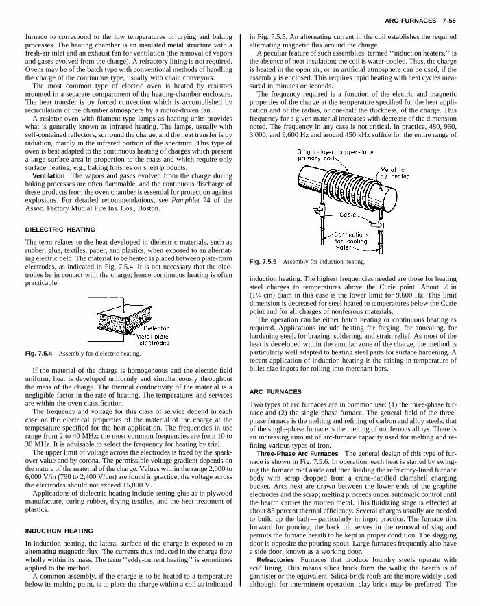
ARC FURNACES 7-55
furnace to correspond to the low temperatures of drying and bakingprocesses. The heating chamber is an insulated metal structure with afresh-air inlet and an exhaust fan for ventilation (the removal of vaporsand gases evolved from the charge). A refractory lining is not required.Ovens may be of the batch type with conventional methods of handlingthe charge of the continuous type, usually with chain conveyors.
The most common type of electric oven is heated by resistorsmounted in a separate compartment of the heating-chamber enclosure.
in Fig. 7.5.5. An alternating current in the coil establishes the requiredalternating magnetic flux around the charge.
A peculiar feature of such assemblies, termed ‘‘induction heaters,’’ isthe absence of heat insulation; the coil is water-cooled. Thus, the chargeis heated in the open air, or an artificial atmosphere can be used, if theassembly is enclosed. This requires rapid heating with heat cycles mea-sured in minutes or seconds.
The frequency required is a function of the electric and magneticproperties of the charge at the temperature specified for the heat appli-
Copyright (C) 1999 by The McGraw-Hill Companies, Inc. All rights reserved. Use ofthis product is subject to the terms of its License Agreement. Click here to view.
The heat transfer is by forced convection which is accomplished byrecirculation of the chamber atmosphere by a motor-driven fan.
A resistor oven with filament-type lamps as heating units provideswhat is generally known as infrared heating. The lamps, usually withself-contained reflectors, surround the charge, and the heat transfer is byradiation, mainly in the infrared portion of the spectrum. This type ofoven is best adapted to the continuous heating of charges which presenta large surface area in proportion to the mass and which require onlysurface heating, e.g., baking finishes on sheet products.
Ventilation The vapors and gases evolved from the charge duringbaking processes are often flammable, and the continuous discharge ofthese products from the oven chamber is essential for protection againstexplosions. For detailed recommendations, see Pamphlet 74 of theAssoc. Factory Mutual Fire Ins. Cos., Boston.
DIELECTRIC HEATING
The term relates to the heat developed in dielectric materials, such asrubber, glue, textiles, paper, and plastics, when exposed to an alternat-ing electric field. The material to be heated is placed between plate-formelectrodes, as indicated in Fig. 7.5.4. It is not necessary that the elec-trodes be in contact with the charge; hence continuous heating is oftenpracticable.
Fig. 7.5.4 Assembly for dielectric heating.
If the material of the charge is homogeneous and the electric fielduniform, heat is developed uniformly and simultaneously throughoutthe mass of the charge. The thermal conductivity of the material is anegligible factor in the rate of heating. The temperatures and servicesare within the oven classification.
The frequency and voltage for this class of service depend in eachcase on the electrical properties of the material of the charge at thetemperature specified for the heat application. The frequencies in userange from 2 to 40 MHz; the most common frequencies are from 10 to30 MHz. It is advisable to select the frequency for heating by trial.
The upper limit of voltage across the electrodes is fixed by the spark-over value and by corona. The permissible voltage gradient depends onthe nature of the material of the charge. Values within the range 2,000 to6,000 V/in (790 to 2,400 V/cm) are found in practice; the voltage acrossthe electrodes should not exceed 15,000 V.
Applications of dielectric heating include setting glue as in plywoodmanufacture, curing rubber, drying textiles, and the heat treatment ofplastics.
INDUCTION HEATING
In induction heating, the lateral surface of the charge is exposed to analternating magnetic flux. The currents thus induced in the charge flowwholly within its mass. The term ‘‘eddy-current heating’’ is sometimesapplied to the method.
A common assembly, if the charge is to be heated to a temperaturebelow its melting point, is to place the charge within a coil as indicated
cation and of the radius, or one-half the thickness, of the charge. Thisfrequency for a given material increases with decrease of the dimensionnoted. The frequency in any case is not critical. In practice, 480, 960,3,000, and 9,600 Hz and around 450 kHz suffice for the entire range of
Fig. 7.5.5 Assembly for induction heating.
induction heating. The highest frequencies needed are those for heatingsteel charges to temperatures above the Curie point. About 1⁄2 in(11⁄4 cm) diam in this case is the lower limit for 9,600 Hz. This limitdimension is decreased for steel heated to temperatures below the Curiepoint and for all charges of nonferrous materials.
The operation can be either batch heating or continuous heating asrequired. Applications include heating for forging, for annealing, forhardening steel, for brazing, soldering, and strain relief. As most of theheat is developed within the annular zone of the charge, the method isparticularly well adapted to heating steel parts for surface hardening. Arecent application of induction heating is the raising in temperature ofbillet-size ingots for rolling into merchant bars.
ARC FURNACES
Two types of arc furnaces are in common use: (1) the three-phase fur-nace and (2) the single-phase furnace. The general field of the three-phase furnace is the melting and refining of carbon and alloy steels; thatof the single-phase furnace is the melting of nonferrous alloys. There isan increasing amount of arc-furnace capacity used for melting and re-fining various types of iron.
Three-Phase Arc Furnaces The general design of this type of fur-nace is shown in Fig. 7.5.6. In operation, each heat is started by swing-ing the furnace roof aside and then loading the refractory-lined furnacebody with scrap dropped from a crane-handled clamshell chargingbucket. Arcs next are drawn between the lower ends of the graphiteelectrodes and the scrap; melting proceeds under automatic control untilthe hearth carries the molten metal. This fluidizing stage is effected atabout 85 percent thermal efficiency. Several charges usually are neededto build up the bath—particularly in ingot practice. The furnace tiltsforward for pouring; the back tilt serves in the removal of slag andpermits the furnace hearth to be kept in proper condition. The slaggingdoor is opposite the pouring spout. Large furnaces frequently also havea side door, known as a working door.
Refractories Furnaces that produce foundry steels operate withacid lining. This means silica brick form the walls; the hearth is ofgannister or the equivalent. Silica-brick roofs are the more widely usedalthough, for intermittent operation, clay brick may be preferred. The

7-56 ELECTRIC FURNACES AND OVENS
slags of acid-lining practice remove no phosphorus or sulfur. Essen-tially all ingot operations are carried on with basic linings. This meansmagnesite bottom and sidewalls, so that the limey slags employed willnot erode them. Entry ports for the electrodes may be of extra-qualityrefractories to prolong roof life, particularly where the furnace is incontinuous operation. In basic practice phosphorus joins the slag read-ily; sulfur can be removed next by a second slag, when this slag hasbeen made highly reducing. Slag covering the molten bath serves in
verting scrap charges into steel for pouring into ingots, castings, or acontinuous caster. This type of equipment finds increasing use also inthe cold melting and duplexing of gray and white irons. Hand and chutecharging have practically disappeared, at least insofar as furnaces of aton charge size upward are concerned. One of the main advantages ofthe top-charge furnace is that the scrap used does not need to be cut todoor size, as was the case formerly.
Although first employed only for the more expensive grades of steel,the arc furnace now is used widely in making ingots for rolling intomctoagbtbnS
wktcpfmm
iimhR
trnahsTctTtstawd
T
D
o
Copyright (C) 1999 by The McGraw-Hill Companies, Inc. All rights reserved. Use ofthis product is subject to the terms of its License Agreement. Click here to view.
refining the metal and reduces the heating of wall and roof brick. Inmodern arc furnace operations, foamy slag practice is employed,wherein a deep, foamy slag prevents the arcs from damaging the walland roof linings. Superrefractories find application in high-temperature,long-refining operations. Electric irons are made in acid-lined furnaces.
Fig. 7.5.6 Three-phase arc furnace with basic lining.
Temperature Arcs approximate 6,300°F (3,500°C); hence opera-tion must be carried out so as to protect the refractories as much aspossible. As the top-charge furnace now has supplanted the door-chargefurnace in nearly all cold-melt work, the conditions for shielding therefractories during the melt-down stage of each heat are good. With thefurnace filled to the top with scrap, the electrodes bore down throughthat scrap, and the heat of the arcs is liberated right in the metalliccharge itself. When the charge, and any back charges made, approachthe fluid stage it is customary to reduce both the power input and thelength of arcs employed. During the finishing stages, roof and sidewallsare protected both by the slag and by the ‘‘umbrella’’ effect of theelectrodes themselves. Deserving mention is the expanding use of oxy-gen to gain speed in production, which makes for increasing furnacetemperatures. The higher sidewalls of modern furnaces aid in obtaininggood roof life. Additionally, water-cooled sidewalls extend refractorylife and thus minimize the cost of replacing refractory.
Charges The three-phase arc furnace is primarily a unit for con-
erchant bars and similar grades and supplies liquid metal fed into aontinuous caster. The speed of production on this type of working—ermed single-slag dephosphorizing basic practice—can be double thatbtained with the same furnace used to make two slag dephosphorizednd desulfurized basic alloy steels. Acid working on foundry steelsenerally approximates the same speed as single-slag dephosphorizingasic practice, and some alloy steels require about half again as muchime. While most carbon steel for castings is made on an acid hearth, aasic bottom is regularly used for making manganese steels, for refiningickel and copper, and for the furnacing of many heat-resistant alloys.ection 13.1 discusses steel-foundry practice.In general, approximately 320 kWh at 100 percent thermal efficiency
ill be needed to melt 1 ton of cold steel scrap. This means about 400Wh will be needed to fluidize each ton. Additionally, about 100 kWh/on will be needed to finish the heat and superheat the bath—this in thease of ordinary plain carbon steels made on single-slag acid or basicractice. Double-slag steel heats will require no more power than othersor fluidizing the scrap charge, but the additional power needed forelting new slag, refining, melting added alloys, etc., may require asuch as 250 kWh/ton of bath, or even more.Three-phase arc furnaces are usually given an hourly productive rat-
ng in terms of acid foundry steels when these equipments are suppliedn sizes up to and including the 11-ft (3.4-m) diam unit. However, withany furnaces extra-powered, quite a few shops exceed the normal
ourly rating considerably—in some cases by essentially 100 percent.epresentative sizes of furnaces are listed in Table 7.5.2.Arcs The arc in each phase is maintained between the lower end of
he electrode and the top of the charge (or bath, after the molten state iseached). Higher voltages can serve for melting as the size of the fur-ace increases; thus, where a 7-ft (2.1-m) diam furnace employs 215 Vs its highest melting potential, a 15-ft furnace would use 290 V origher as the top tap. For such a furnace constructed with water-cooledidewall and roof panels, the application of 500 V would be normal.he furnace transformer is universally of the motor-operated tap-hanger type, and in the case of, say, a 10,000 kVA at 55°C rise substa-ion, a secondary voltage variation of more than 150 V is customary.he range of lower voltages used for refining the molten metal is ob-
ained by changing the primary of the main transformer from delta totar connection; this reduces both voltage and capacity to 58 percent ofheir values with delta primary connection. If, say, 12 tons of steel scrapre to be melted down to fluid in 1 h, then the electric energy neededill approximate 5,000 kWh. With 245 V used as the principal melt-own voltage, the current per phase will have to average close to
able 7.5.2 Sizes of Three-Phases Arc Furnaces
Normal productiveiam of Normal charge, Normal powering, rate, single-slag
shell, ft tons kVA steels, tons/h*
5 11⁄2 600 1⁄27 31⁄2 1,500 11⁄29 8 3,000 3
11 16 6,000 6121⁄2 27 9,000 915 50 12,500 1320 115 25,000 2724 225 36,000 40
* Many users exceed these outputs, particularly those using burners and oxygen to speedperations.

INDUCTION FURNACES 7-57
12,000 A. A 12-in (30-cm) diam graphite electrode would amply carrythis current. Small furnaces operate with 600 kVa and even higherpowering per ton of charge, whereas in the case of the larger equipmentsthe electrical backing of the furnace normally does not exceed 300kVA/ton of charge.
Reactance is required in the circuits of an arc furnace to give stabilityand to limit the current when an electrode makes contact with the metal-lic charge. The inherent reactance (impedance) in the instance of
porated in the metal since the bath washes over much of the interior of arocking furnace. The oscillation approximates 200°.
Rocking furnaces usually do not exceed 500 kW in powering. Asingle operating voltage can suffice. In regulating a rocking furnace,only one electrode need be movable, on a carriage under automaticcontrol, to maintain the requisite amperage by varying the length, andtherefore the resistance, of the arc gap.
Copyright (C) 1999 by The McGraw-Hill Companies, Inc. All rights reserved. Use ofthis product is subject to the terms of its License Agreement. Click here to view.
10,000-kVa installations and above normally is sufficient. The totalstabilizing reactance provided in the case of a 1,000-kVa load normallyapproximates 30 percent.
Regulation The characteristics of an arc furnace circuit for a givenapplied voltage are shown in Fig. 7.5.7. For each voltage there is a valueof current that gives maximum power in the furnace. This optimumcurrent is the basis of the regulation of the circuit.
Fig. 7.5.7 Characteristics of an arc furnace circuit.
The control of the power input into direct-arc electric furnaces iseffected by the adjustment of the arc length. To accomplish this, theelectrode arms are positioned in the ‘‘raise’’ or in the ‘‘lower’’ direc-tion by an automatic regulator. This regulator, which responds withina few cycles, causes the electrode arms to be lowered by extra-fastmotor-driven winches when voltage is obtained by closing the circuitbreaker. As soon as contact between electrode and scrap charge is es-tablished, melting current flows, and this current, whenever exces-sive, functions immediately through the medium of the winch motorto elevate that particular electrode arm and electrode by the distancecorresponding to the diminution in power input needed just at that in-stant.
Formerly, the so-called contactor regulator was used universally toenergize the winch motors. More recently the rotary regulator—this, ineffect, being a particularly responsive motor generator set for each ofthe three phases—has forged to the forefront by reason of giving moreprecise control with minimized maintenance. Currently, even faster re-sponse and electrode-travel speed are provided by low-inertia static-regulating equipment.
Single-Phase Arc Furnaces Single-phase arc furnaces usually aremanufactured in the two-electrode type. When the electrodes operatevertically, the furnace melts much as a three-phase direct-arc furnacedoes. However, most vertical-electrode single-phase furnaces are oflaboratory size—that is, up to 150 kVa in powering.
When two electrodes are mounted horizontally in a rocking furnacean indirect-arc unit is obtained. Many rocking furnaces serve well in themelting of brasses, bronzes, and in similar work. Volatiles are reincor-
INDUCTION FURNACES
There are two basic types of metal-melting induction furnaces: (1) core-less and (2) core-type. Both types utilize the principle of a transformer.The high-voltage circuit is coupled with that of the low voltage withoutdirectly connecting the two circuits. The element responsible for thiscoupling effect is the magnetic field. Induction heating utilizes theproperty of the magnetic field, which enables heat to be transferredwithout direct contact. By correctly disposing the high-voltage winding,which in the case of the induction furnace would be an induction coil orinductor, the magnetic field is directed so that the metal to be heated ormelted is made to absorb energy. The temperature attainable is limitedsolely by the resistance to heat of the surrounding lining material. In-duction heating enables any temperature to be achieved while providingfor excellent regulation of temperature and metallurgical properties.Any metal which will conduct electric current can be melted in aninduction furnace.
Coreless Induction Furnaces (See Fig. 7.5.8.) This type of furnaceconsists of a crucible, copper coil, and framework on supports arrangedfor tilting and pouring. The specially designed induction coil acts as theprimary of the transformer. The crucible conforms to conventional re-fractory practice. A rammed crucible is used for furnaces above 50 kW,and preformed crucibles are used on smaller furnaces such as laboratoryunits.
Fig. 7.5.8 Coreless induction furnace.
The principle of operation is essentially the same as that of the induc-tion heater previously described. The initial charge in the furnace is coldscrap metal—pieces of assorted dimensions and shapes and a largepercentage of voids. As the power is applied and the heat cycle pro-gresses, the charge changes to a body of molten metal; additional coldmetal is added until the molten-metal level is brought to the desiredtemperature and metallurgical chemistry. The furnace then is tapped.
When the metal in the furnace becomes fluid, depending on whether aline frequency or medium-frequency supply by means of convectors isused, a certain electromagnetic stirring action will occur. This stirring

7-58 ELECTRIC FURNACES AND OVENS
action is peculiar to the induction furnace and aids in the production ofcertain types of alloys. The stirring action increases as the frequency isreduced.
Line-frequency applications are generally reserved to furnaces hav-ing a metal-holding capacity of 800 lb (360 kg) and above. There isalways an ideal relationship between the size of a coreless furnace andits operating frequency. As a general rule, a small furnace gives bestresults at high to medium frequencies and large furnaces work best at
The melting output is controlled by varying the voltage supplied tothe inductors with the aid of a variable-voltage transformer connected tothe primary circuit of the supply. Core-type furnaces always use linefrequencies. Voltage or power-input regulation, therefore, can be per-formed by adjusting the tap setting of the transformer feeding the fur-nace transformer attached to the furnace shell. These transformers aresingle-phase units, and by using three such units, a balanced three-phaseinput can be obtained. The current flowing through the primary induc-tors by transformation causes a much larger current in the metal loop,w
bna
tncrtm
poct
s
PF
Tgr
T
BBBAAHTAVVG
LSTZBSSG
ACFGPSS
Copyright (C) 1999 by The McGraw-Hill Companies, Inc. All rights reserved. Use ofthis product is subject to the terms of its License Agreement. Click here to view.
the lower frequencies. A frequency is suited to a given furnace when ityields good, fast melting with a gentle stirring action. Too high or toolow frequencies are accompanied by undesirable side effects. The tabu-lation below gives the charge weights and frequencies generally to beused:
Charge Frequency,weight, lb Hz
2–50 9,60012–500 3,000
200–15,000 960800–75,000 60
The coreless induction furnace is usually charged full and tappedempty, although at line frequencies, it may be necessary to retain acertain amount of metal in the furnace to continue the operation, since itis difficult to start the furnace with small metal particles, such as turn-ings and borings, in a cold crucible. As a result, it is general practice toretain a heel in the furnace of about one-third its molten-metal volume.This problem can be avoided in furnaces of higher frequencies, wherestart-up can be performed with small-size metal charges without carry-ing the heel.
Coreless induction furnaces are particularly attractive for meltingcharges and alloys of known analysis; in essence, the operation be-comes one of metal melting with rapidly absorbed electric heat withoutdisturbing the metallurgical properties of the initial charge.
These furnaces are supplied from a single-phase source. In order toobtain a balanced three-phase input, it is necessary specifically to designthe electrical equipment for the inclusion of capacitors and suitablereactors, which are generally automatically switched (by inductancechanges) during the operation in order to provide a reasonably highpower factor. Power factors on such furnaces can be kept at or nearunity. In high-frequency coreless induction furnaces, high power factorsare necessary to prevent overburdening the motor-generator equipment.
Core-Type Induction Furnaces (See Fig. 7.5.9.) The transformer isactually wound to conform to a typical transformer design having aniron core and layers of wire acting as a primary circuit. The meltingchannel acts as a ring short circuit around this transformer in the meltingchamber. According to the desired melting capacity, one, two, or threesuch transformers (or inductors, as they are called) may be added to thefurnace shell. At all times, the channel must hold sufficient metal tomaintain a short circuit around the transformer core. Air cooling is usedas required to prevent undue heating of the inductor coils and magneticcores.
Fig. 7.5.9 Core-type induction furnace.
hose resistance creates heat for melting.The core-type furnace is the most efficient type of induction furnace
ecause its iron core concentrates magnetic flux in the area of the mag-etic loop, ensuring maximum power transfer from primary to second-ry. Efficiency in the use of power can be as high as 95 to 98 percent.
The essential loop of metal must always be maintained in the core-ype furnace. If this loop is allowed to freeze by cooling, extreme care isecessary in remelting because the loop may rupture and disrupt theircuit. This could require extensive work in dismantling the coil andestoring the loop. Consequently, core-type furnaces rarely are permit-ed to cool. This makes alloy changes difficult because a heel of moltenetal always is required.The relatively narrow melting channels must be kept as clean as
ossible since a high metal temperature exists in this loop. Nonmetallicsr tramps in the charge metal tend to accumulate on the walls in thehannel area, restricting the free flow of metal and ultimately closinghe passage.
This furnace is particularly useful for melting of nonferrous metalsuch as aluminum, copper, copper alloys, and zinc.
OWER REQUIREMENTSOR ELECTRIC FURNACES
he energy required for melting metals in electric furnaces varies for aiven metal or alloy with the size of the furnace, the thickness of theefractory lining, the temperature of the molten metal, the rate of melt-
able 7.5.3 Energy Consumption of Electric Furnaces
Process Type of furnace lb/kWh
aking finishes on sheet metal Batch oven 10–18aking finishes on sheet metal Continuous oven 25–30aking bread Continuous oven 10–12nnealing brass and copper Batch furnace 10–25nnealing steel Batch furnace 5–15ardening steel Batch furnace 7–11empering steel Batch furnace 15–25nnealing glass Continuous furnace 40–100itreous enameling, single coat Batch furnace 5–8itreous enameling, single coat Continuous furnace 10–15alvanizing Batch furnace 12–20
kWh/tonMelting metals Type of furnace (2,000 lb)
ead Resistor 40–50older 50–50 Resistor 40–50in Resistor 35–50inc Induction 80–100rass Arc and induction 250–400teel, melting only Arc and induction 450–700teel, melting and refining Arc 600–750ray iron Arc and induction 450–600
kWh/tonFurnace products Type of furnace (2,000 lb)
luminum Electrolytic 22,000–27,000alcium carbide Resistance 3,000–6,000erroalloys Resistance 4,000–8,000raphite Resistance 3,000–8,000hosphoric acid Resistance 5,000–6,000ilicon carbide Resistance 8,500–10,000melting iron ore Resistance 1,650–2,400

SUBMERGED-ARC AND RESISTANCE FURNACES 7-59
ing, and with the degree of the continuity of the operation of the furnace.An estimated efficiency of 50 to 60 percent is often used for preliminarypurposes. As is well known, 3- to 6-ton direct-arc furnaces often areused to tap acid foundry steels with the consumption of less than 500kWh to the ton, and large ingot furnaces of this same type, operatingbasic-lined on common steels for ingots, give even better results despitethe call for several more charges of scrap per heat.
Average values in kWh/ton of molten metal are as follows: yellow
terials in batches and is usually rectangular in shape with an electrode ateach end for single-phase operation. The length and cross-sectional areaof the path of the current are proportioned to suit the power characteris-tics of the charge. Refractory materials have negative temperature-re-sistance coefficients, and hence to maintain constant power in the fur-nace circuit the applied voltage must be reduced as the temperature ofthe charge rises in proportion to the square root of the ratio of the initialresistance of the furnace circuit to the resistance of the furnace circuit atthe end of the heat cycle. If the materials of the charge are nonconduc-
Copyright (C) 1999 by The McGraw-Hill Companies, Inc. All rights reserved. Use ofthis product is subject to the terms of its License Agreement. Click here to view.
brass, 200 to 350; red brass, 250 to 400; copper, 250 to 400; lead, 30 to50; steel melting, when making high-quality double-slag basic heats,650 to 800 (Table 7.5.3).
Electrode consumption varies considerably in arc furnaces because oftheir different constructions and operations. Average values in poundsof electrode per ton of molten metal are: steel melting, with graphiteelectrodes, 5 to 10; brass melting, with graphite electrodes, 3 to 5.Graphite electrodes have largely superseded carbon electrodes.
SUBMERGED-ARC AND RESISTANCE FURNACES
The resistance furnace is essentially a refractory-lined chamber withelectrodes—movable or fixed—buried in the charge. This simplicitypermits a wide range of designs and much latitude in dimensions. Thegeneral service is heating charges of a refractory nature to bring aboutchemical reactions or changes in the physical structure of the material ofthe charge. The energy requirement of each of such processes is a largeitem in the cost of production. Large units and a favorable power loca-tion are the rule. Resistance furnaces also are termed submerged-arcfurnaces and/or, in quite a few instances, smelting-type furnaces.
The only limit on the temperature to which a charge can be heated bythis method is the temperature at which the materials of the charge arevaporized. For temperatures beyond the limit of refractory linings, thematerials of the charge are used to form a protective layer between thecore of the charge (through which the current passes) and the walls ofthe furnace.
Resistance furnaces with movable electrodes may be either single-phaseor polyphase. The materials of the charge are fed more or less continu-ously, and the product is discharged intermittently or continuously asrequired. In some cases the product is in the molten state; in othersthe product is a vapor. The usual method of operation is the use of asingle operating voltage and a constant power input. The power is regu-lated by adjustment of the depths of the electrodes in the charge.The load is fairly uniform and, if polyphase, is kept reasonably wellbalanced.
The resistance furnace with fixed electrodes is designed for heating ma-
tors at room temperature, a starting circuit is provided by means of acore of carbon—usually coke—placed in the charge. The heat cyclesof furnaces of this class generally extend over a period of several days.
Some of the more common uses of the resistance furnace are:Calcium carbide furnaces are charged continuously with lime and
coke. These equipments can be either open or closed top. This type offurnace has been built up to 70,000 kVA in electrical powering—covered and sealed for gas collection.
Ferroalloy furnaces for the production of ferrochrome, ferrosilicon,ferromanganese, etc., are usually three-phase furnaces with movableelectrodes and are similar in construction to the three-phase arc furnace.The charge is a mixture of the ore (oxide) of the selected metal, scrapiron, and a reducing agent, generally carbon except for very low carboncontent alloys, for which some other reducing agent such as aluminumor silicon is required. Six-electrode furnaces often are used for powerinputs of 15,000 kVA and more.
The graphitizing furnace is of the single-phase batch type. Artificialgraphite is made by heating amorphous carbon (coal or coke) whileshielded from air to a high temperature—around 4,500°F (2,500°C).The presence of some metallic impurity, such as iron oxide, in thecharge appears to be necessary for the conversion of amorphous carbonto graphitic carbon. The raw material for making bulk graphite consti-tutes both the charge and the protective layer around the core of thecharge. Graphite shapes are made from the corresponding shapes ofamorphous carbon which are embedded—between the electrodes—inraw material as noted for the manufacture of bulk graphite.
The silicon carbide furnace is similar to the graphitizing furnace. Thecharge is a mixture of sand (silica), coke, sawdust, and a small amountof salt. This mixture is packed around a core of granulated coke to formthe initial circuit between the electrodes. The sand and coke are thereacting materials. The sawdust serves to make the charge porous sothat the gases formed during the heating of the charge can escape freely.The salt vaporizes and removes impurities, such as iron, in the form ofchlorides. The temperature of the process is 2,700 to 3,400°F (1,500 to1,880°C).