fuel flow/pressure - buy-ei.com
TRANSCRIPT

II 05069315/6/93
Rev. I: 7/2/02
Installation Instructions(FP-5 and FP-5L)
Fuel Flow/Pressure
2.5"
2.5"
3.65"
Electronics International Inc. ®63296 Powell Butte Hwy • Bend, OR 97701 • (541) 318-6060 • www.Buy-EI.com
Unit Model:__________________
Flow Transducer Model:__________________
S/N:_____________________
S/N:_____________________
You must read this manual before installing or operating the instrument. Thismanual contains warranty and other information that may affect your decision
to install this product and/or the safety of your aircraft.

Important Notice***** MUST READ *****
If you think it is not important to read this manual, you're wrong! This manualcontains important installation information that may affect the safety of your air-craft, delay your installation or affect the operation of your instrument. You Mustread this manual prior to installing your instrument. Any deviation from theseinstallation instructions is the sole responsibility of the installer/pilot and mayrender the STC invalid.
Read the Warranty / Agreement. There is information in the Warranty / Agreement that may alteryour decision to install this product. If you do not accept the terms of the Warranty / Agreement, do notinstall this product. This product may be returned for a refund. Contact Electronics International inc. fordetails.
A gravity feed fuel system or any engine rated over 300 H.P. must use an FT-90 flow trans-ducer. An engine rated over 550 H.P. must use the FT-180 flow transducer. The standard FuelTransducer (FT-60) shipped with the FP-5 or FP-5L Fuel Flow/Pressure instrument is intended tobe used on aircraft equipped with fuel pumps with engines rated below 300 H.P.
Transducer Identification Markings: There are two suppliers of the FT-60 and FT-90 FlowTransducer (E.I. inc and Flowscan). The E.I. units are equipped with a PMA label.
FT-60 - The Flowscan unit is marked "201" on the top of the unit.FT-90 - The Flowscan unit is marked "231" on the top of the unit.FT-180 - Equipped with a 3/4 - 16 male fitting.
On a gravity feed system the fuel pressures are lower than the FP-5 or FP-5L can measure.Therefore, disable the Fuel Pressure feature on the FP-5 or FP-5L when used on a gravity feedsystem.
If your aircraft is not covered on our STC (found at the back of this manual), you mustperform the flow and pressure tests in FAA document A.C. 23.955-1 (Substantiating Flow Ratesand Pressures in Fuel Systems of Small Airplanes) to insure safe and proper operation.
Installation of the FP-5 on an aircraft with a fuel return line from the Pressure Carburetor requiresa FFDM-1 Differential Module (see price sheet).
The placard "Do Not Rely on Fuel Flow Instrument to Determine Fuel Levels in Tanks" must bemounted on the aircraft instrument panel near the FP-5.
If the aircraft is equipped with a primary fuel flow and/or pressure instrument, the followingplacard must be mounted on the aircraft instrument panel near the FP-5: "Refer to Original Fuel Flow/Pressure Instrumentation for Primary Information".

ContentsWarranty ................................................................................................... 2
1. Important Information and Initial Check Out: .................................... 3
2. Install the Fuel Flow Transducer: ....................................................... 4
3. Install A Functional Module: ............................................................... 5
4. Install the Circular Connector: ........................................................... 5
5. Route the Power and Ground Wires: .................................................. 6
6. Route the Backlight Wires: ................................................................. 6
7. Route the (Optional) External Warning Control Line: ........................ 6
8. Route the Fuel Flow Transducer Wires: ............................................. 6
9. Install A Functional Module: ............................................................... 7
10. (FP-5L Only) Connect the RS-232/422 Input Lines: ......................... 7
11. (FP-5L Only) Connect the RS-232 Output Line: ................................ 8
12. Install the Fuel Flow Differentail Module (FFDM-1) .......................... 8
13. Install the Instrument in the Panel: ................................................... 9
14. Connect the Circular Connector to the Instrument: ......................... 9
15. System Check-out: ............................................................................. 9
16. Initial Programming: ........................................................................... 10
Wiring Diagrams ....................................................................................... 11
Circular Connectors ................................................................................. 13
Specifications and Operating Features ................................................... 15
Fuel Flow Transducer Installation Drawings: ...................................... 17-20
STC Information ...................................................................................... Appendix
1
2
Warranty / AgreementElectronics International Inc. (E.I. inc.) warrants this instrument and system components to be free fromdefects in materials and workmanship for a period of one year from the user invoice date. Fuel Flowand Pressure Transducers are NOT covered under this warranty. They are covered by the originalequipment manufacturer. Electronics International Inc. will repair or replace any item, at its sole discre-tion, covered under the terms of this Warranty provided the item is returned to the factory prepaid.
1. This Warranty shall not apply to any product that has been repaired or altered by any person otherthan Electronics International Inc., or that has been subjected to misuse, accident, incorrect wiring,negligence, improper or unprofessional assembly or improper installation by any person. This warrantydoes not cover any reimbursement for any person’s time for installation, removal, assembly or repair.Electronics International retains the right to determine the reason or cause for warranty repair.
2. This Warranty does not extend to any machine, vehicle, boat, aircraft or any other device to whichthe Electronics International Inc. product may be connected, attached, interconnected or used in conjunc-tion with in any way.
3. The obligation assumed by Electronics International Inc. under this Warranty is limited to repair,replacement or refund of the product, at the sole discretion of Electronics International Inc.
4. Electronics International Inc. is not liable for expenses incurred by the customer or installer due tofactory updates, modifications, improvements, upgrades, changes, or any other alterations to the productthat may affect the form, fit, function or operation of the product.
5. Personal injury or property damage due to misinterpretation or lack of understanding of this product is solelythe pilot's responsibility. The pilot must understand the operation of this product before flying the aircraft. Donot allow anyone to operate the aircraft that does not know the operation of this product. Keep the OperatingManual in the aircraft at all times.
6. E. I. Inc. is not responsible for shipping charges or damages incurred under this Warranty.
7. No representative is authorized to assume any other liability for Electronics International Inc. inconnection with the sale of Electronics International Inc. products.
8. If you do not agree to and accept the terms of this Warranty, you may return the product for arefund.
This Warranty is made only to the original user. THIS WARRANTY IS IN LIEU OF ALL OTHERWARRANTIES OR OBLIGATIONS: EXPRESS OR IMPLIED. MANUFACTURER EXPRESSLYDISCLAIMS ALL IMPLIED WARRANTIES OF MERCHANTABILITY OR FITNESS FOR APARTICULAR PURPOSE. PURCHASER AGREES THAT IN NO EVENT SHALL MANUFAC-TURER BE LIABLE FOR SPECIAL, INCIDENTAL OR CONSEQUENTIAL DAMAGES, IN-CLUDING LOST PROFITS OR LOSS OF USE OR OTHER ECONOMIC LOSS. EXCEPT ASEXPRESSLY PROVIDED HEREIN, MANUFACTURER DISCLAIMS ALL OTHER LIABILITYTO PURCHASER OR ANY OTHER PERSON IN CONNECTION WITH THE USE OR PERFOR-MANCE OF MANUFACTURER’S PRODUCTS, INCLUDING SPECIFICALLY LIABILITY INTORT.

FP-5 and FP-5LInstallation Instructions
1. Important Information and Initial Check Out:
A. The installer and aircraft owner must read the Warranty before starting the installation. There isinformation in the Warranty that may alter your decision to install this instrument. If you do not acceptthe terms of the Warranty, do not install this instrument.
B. If you are not an FAA Certified Aircraft Mechanic familiar with the issues of installing aircraft fuelflow and pressure instruments, Do Not attempt to install this instrument. The installer should usecurrent aircraft standards and practices to install this instrument (refer to AC 43.13).
C. Check that any necessary FAA Approvals (STCs, etc.) are available for your aircraft before startingthe installation. The FAA Approved Model List (AML) is located at the back of this manual. Re-solve any issues you may have before starting the installation.
D. Before starting installation, read the entire Installation Instructions and resolve any installation, operatingand performance issues you may have before starting the installation.
E. THIS INSTALLATION WILL REQUIRE SOME PARTS UNIQUE TO YOUR AIRCRAFT THATARE NOT SUPPLIED IN THE KIT (including, but not limited to hoses and fittings). Acquire all theparts necessary to install this instrument before starting the installation.
F. Check that the instrument and flow transducer make and model are correct before starting the installation(check your invoice and the markings on the side of the instrument). A gravity feed fuel system or anyengine rated over 300 H.P. must use an FT-90 flow transduer. A pressure carbureted engine with afuel return line requires an FFDM-l (see price sheet).
Transducer Identification Markings: There are two suppliers of the FT-60 and FT-90 FlowTransducer (E.I. inc and Flowscan). The E.I. units are equipped with a PMA label.
FT-60 - The Flowscan unit is marked "201" on the top of the unit.FT-90 - The Flowscan unit is marked "231" on the top of the unit.FT-180 - Equipped with a 3/4 - 16 male fitting.
G. Before starting the installation make sure the unit will fit in the location you intend to install it withoutobstructing the operation of any controls.
H. If this instrument is to replace an existing unit in the aircraft, it is the installer's responsibility to move orreplace any existing instruments or components in accordance with FAA approved methods and proce-dures. The following Installation Instructions do not cover moving or the removal of any existinginstruments or components.
3 Rev. I: 7/2/02

4
2. Install the Fuel Flow Transducer:
Mount the Fuel Flow Transducer using the appropriate drawing at the back of this manual.
The instructions listed below must be followed when installing a Fuel Flow Transducer.
Note: If your engine is equipped with a Pressure Carburetor with a fuel return line from the carburetor back to thefuel tank, you will need to install two flow transducers: one in the feed line from the fuel pump to the carburetorand one in the return line from the carburetor back to the fuel tank. Also, a Fuel Flow Differential Module(FFDM-1) will need to be installed. See drawings 1229932 and 1015941 at the back of this manual.
A. The transducer output port should be mounted lower, even or no more than 4" per foot higher than thecarburetor inlet port (or fuel servo on a fuel injected engine). If this is not possible, a loop should be putin the fuel line between the Fuel Flow Transducer and the carburetor or fuel servo (see diagram below).
Fuel Flow Transducer
WiresUP
1/4" NPT
• Mount the transducer withthe wires pointing up.
Note: • The direction of the flow offuel through the transduceris marked on the trans-ducer.
End View Side ViewIf the transducer is more than 4" per foot higherthan the carburetor or fuel servo port, put a loopin the fuel line between the transducer and thecarburetor or fuel servo. This will allowbubbles to vacate the Flow Transducer.
B. Do not remove the caps on the flow transducer until the fuel hoses are ready to be installed.
C. The flow of fuel through the transducer must follow the direction marked on the transducer.
Fuel Flow Transducer Carburetor orFuel Servo
Aircraft Configuration Drawing # Page
Fuel injected engine without a fuel return linefrom the fuel servo (most Lycomings).
1229932 or1229931 18 or 17
Fuel injected engine with a fuel return line fromthe fuel servo (most Continentals). 0415941 20
Carbureted engine with a fuel pump and no fuelreturn line.
1229932 or1229931 18 or 17
Carbureted engine with a fuel pump and a fuelreturn line (requires an FFDM-1 Module).
1229932 or1229931, and1015941
18 or 17, and 19
Carbureted engine with a gravity feed fuelsystem (requires an FT-90 Flow Transducer).
1229932 or1229931 18 or 17
Rev. I: 7/2/02
OUT

5
D. The flow transducer must be mounted so the wires exiting the transducer are pointing up.
E. Before connecting any hoses, thoroughly clean them and insure they are free of any loose material. Highair pressure may be used, however, do not allow high air pressure to pass through the flow transducer.
F. When mounting a Fuel Flow Transducer make provisions for the Fuel Pressure Transducer as necessary.
You may want to consider using some Fittings and Hoses shown below. Note: DO NOT EXCEED a torque of15 ft. lbs. or screw the fittings tighter than two full turns past hand tight, whichever happens first.
Fittings:
#4 Straight - AN816-4-4D#6 Straight - AN816-6D#8 Straight - AN816-7D
#6 45' - MS20823-6D
#4 90' - MS20822-4-4D#6 90' - MS20822-6D
1/4" NPT Flare
Hose Fittings:
Stright - MS24587-XX, Stratoflex 300-, Aeroquip 400-45' - MS27226-XX, Stratoflex 646- and 640, Aeroquip 98000690' - MS27224-XX, Stratoflex 649- and 643, Aeroquip 980005
NOTE: The Stratoflex teflon hose can be much more flexibleand easier to route than most existing hoses. If you have a hardto fit installation, consider this hose.
Flare Hose
3. Install A Functional Module:
A Functional Module is a small box with circuitry used to convert pressure, temperature, voltage, amps, etc.to an appropriate signal the FP-5(L) can display. This signal can be connected to the Aux Channel of the FP-5(L).These modules are small and light and are tie wrapped under the instrument panel. They come with a circularconnector so they may be installed and removed easily.
Install any Functional Module at this time. Installation Instructions for the various Functional Modulescome with the modules and are supplements to this installation manual.
4. Install the Circular Connector:
Starting from under the instrument panel, route the circular connector wire harness up to the instrumentmounting location. (See the Wiring Diagram at the back of this manual). Place the circular connector about 8inches back from the panel. Tie wrap the harness in place approximately 1 foot back from the circular connector.This will allow the harness to be flexible and accommodate varying lengths in instrument wires. Be sure thesewires do not obstruct the freedom of travel of any controls.
Rev. I: 7/2/02

6
5. Route the Power and Ground Wires:
In the wire harness are two sets of red and black 6' wire bundles used for the fuel pressure transducer and thefuel flow transducer. Also, there are red and black 3' wires used for instrument power and ground. Route the 3'red wire in the harness to the aircraft’s 12 or 24 volt main or emergency bus as applicable via an independentcircuit breaker (five amps or less). An alternate method would be to route the red lead to the bus via a one ampin-line fuse. With this method a spare fuse must be kept in the aircraft. Route the 3' black wire in the harness toa good ground . Tie wrap these wires so they do not obstruct the freedom of travel of any controls.
6. Route the Backlight Wires:
Connect the backlight wires as follows:
A. It is recommended to permanently power up the digital display backlight.
1) For a 12-volt system connect the white/brown wire to the bus and connect the white/red wire toground (see Wiring Diagram).
2) For a 24-volt system leave the white/brown wire open and connect the white/red wire to the bus(see Wiring Diagram).
B. Connect the white/orange wire to the panel light rheostat. This wire will dim the Display ModeIndicator LEDs for night operation when the panel lights are turned on. If this line is left open, theDisplay Mode Indicator LEDs will remain at full intensity at all times. Also, if the voltage on this linedrops below 11.5 volts, the analog LEDs will be displayed at full intensity. Tie wrap all wires so theydo not obstruct the freedom of travel of any controls. Note: This line may be connected to the CP-1Intensity Control Pot (see price sheet.
7. Route the (Optional) External Warning Control Line:
The white/yellow wire can be connected to E.I.'s external light (model AL-1), buzzer (model ATG-1), voiceannunciator (model AV-17), a relay, etc. This wire grounds when the red warning light is on. The current in thisline must be limited to 2/10 of an amp maximum. Exceeding this limit will damage the instrument. If this featureis not used, leave this line open. Tie wrap this wire so it does not obstruct the freedom of travel of any controls.
8. Route the Fuel Flow Transducer Wires:
The wire harness includes 6' red, black and white wires bundled together. Route and connect these 6' wiresto the fuel flow transducer. If your engine is equipped with a fuel return line from the carburetor back to the fueltank, route these wires to the Fuel Flow Differential Module (FFDM-1). See the appropriate drawing at the backof this manual.
Be sure the connectors mate properly. If the tab inside the male connector gets bent, it can wedge itselfbetween the red nylon and metal female receptacle. This can result in an intermittent connection after about amonth or more. If the connectors are disconnected several times the female connector can become loose. If thishappens use a pair of needlenose pliers and tighten the metal receptacle inside the female connector.
Rev. I: 7/2/02

Any excess wires can be rolled up and tie wrapped under the instrument panel. Tie wrap these wires so theydo not obstruct the freedom of travel of any controls. If you decide to cut these wires to a specific length, stripeach wire and double the wires over. An extra set of connectors is provided in the kit. Double crimp each con-nector. Doubling the wires over and a good crimp are critical.
Note: A dab or grease or two drops of oil on the red connectors will protect them for many years.
9. Install A Functional Module:
If the Aux channel on the FP-5 is to be used to monitor a function (EGT, TIT, Fuel Pressure, Oil Pressure,etc.) an appropriate Functional Module must be installed. A Functional Module is a small box with circuitry usedto convert Temperature, Pressure, Voltage, Amps, etc. to an appropriate signal the FP-5 can display on the Auxchannel. These modules are small and light and are tie wrapped under the instrument panel. They come with aCircular Connector so they may be installed and removed easily.
Install any Functional Modules at this time. Installation Instructions for the various Functional Modulescome with the modules.
10. (FP-5L Only) Connect the RS-232/422 Input Lines:
Connecting the FP-5L Input Lines to a compatible GPS unit allows the FP-5L to display Fuel to Destination,Fuel Reserve, Nautical Miles per Gallon and Statute Miles per Gallon information. The FP-5L has three GPSReceive Formats: 1. "In1" for all panel mount GPS units (9600 baud); 2. "In2" for Northstar (1200 baud); 3."In3" for hand held GPS units (NEMA at 4800 baud). The protocol is 1 start bit, 8 data bits and 1 stop bit andthe RS-232 update time of the GPS unit should be 1 to 2 seconds. The GPS unit may require some setup. Youmay want to contact a knowledgeable instrument shop or the GPS factory to help with the hookup and setup ofthe GPS unit. See the "Power-Up Programmable Settings" section in the FP-5(L) Operating Instructions toconfigure the FP-5L RS-232 input.
7
Type ofHook-up
FP-5LConnections
GPSConnections
RS-232RS-232 Input(white/blue wire) RS-232 Output
RS-422 orRS-486
RS-232 Input(white/blue wire) - Output
+ Output(connect a 120 ohm resistor between the + Output and - Output)
Note: Do not connect any GPS shield wires to the FP-5L. They should be left open.
Rev. I: 7/2/02

8
11. (FP-5L Only) Connect the RS-232 Output Line:
Connecting the FP-5L Output Line to a compatible GPS unit allows the GPS unit to use the fuel datatransmited by the FP-5L. The FP-5L has three GPS Transmit Formats: 1. "Ot1" outputs older Shadin fuel flowdata (for Arnav, King and newer Garmin GPS units); 2. "Ot2" outputs the Shadin fuel flow sentence (for Garminand other GPS units); 3. "Ot3" outputs a modified Shadin Fuel/Airdata sentence (for UPS GPS units). The GPSunit may require some setup. You may want to contact a knowledgeable instrument shop or the GPS factory tohelp with the hookup and setup of the GPS unit. See the "Power-Up Programmable Settings" section in theFP-5(L) Operating Instructions to configure the FP-5L RS-232 output.
Connect the FP-5L RS-232 Output Line (White/Green Wire) to the GPS RS-232 Input Line. Do not connectany GPS shield wires to the FP-5L. They should be left open.
12. Install the Fuel Flow Differential Module (FFDM-1):
If your engine is equipped with a fuel return line from the carburetor back to the fuel tank, install theFFDM-1 in the aircraft as oulined below (see diagram at the back of this manual). Otherwise, omit this step.
A. Connect the circular connector to the FFDM-1.
B. Install the FFDM-1 under the instrument panel using two tie wraps on each end of the module to supportit to a wire bundle or bracket.
C. Route and connect the 3' red power lead to the 12 or 24 volt bus via a 1 amp fuse.
D. Route and connect the 3' black ground lead to the same ground used for the FP-5.
E. Route and connect the 6' red, black and white leads marked "Feed" to the flow transducer installed in thefuel line from the fuel pump to the carburetor.
F. Route and connect the 6' red, black and white leads marked "Return" to the flow transducer installed inthe return fuel line from the carburetor to the fuel tank.
G. Connect the 1' red, black and white leads to the same color 6' leads from the FP-5.
H. Be sure the connectors mate properly. If the tab inside the male connector gets bent, it can wedge itselfbetween the red nylon and metal female receptacle. This can result in an intermittent connection afterabout a month or more. If the connectors are disconnected several times the female connector canbecome loose. If this happens use a pair of needlenose pliers and tighten the metal receptacle inside thefemale connector.
Any excess wires can be rolled up and tie wrapped under the instrument panel. Tie wrap these wiresso they do not obstruct the freedom of travel of any controls. If you decide to cut these wires to aspecific length, strip each wire and double the wires over. An extra set of connectors is provided in thekit. Double crimp each connector. Doubling the wires over and a good crimp are critical.
Note: The flow transducers for the FFDM-1 and the FP-5 MUST be of the same model (i.e., if the FP-5uses an FT-60 flow transducer, then the FFDM-1 must use a FT-60 flow transducer). Rev. I: 7/2/02

9
13. Install the Instrument in the Panel:
Install the instrument from behind the instrument panel using 6 x 32 screws. These screws must not be anylonger than 1/2". Tie wrap any loose wires as needed. Make sure the instrument and wire do not obstruct theoperation of any controls. Mount the placard "Do Not Rely on Fuel Flow Instrument to Determine Fuel Levelsin Tanks" on the aircraft instrument panel near the FP-5.
If the aircraft is equipped with a primary fuel flow and/or pressure instrument, the following placard mustbe mounted on the aircraft instrument panel near the FP-5: "Refer to Original Fuel Flow/Pressure Instrumenta-tion for Primary Information".
14. Connect the Circular Connector to the Instrument:
A. Push the two mating connectors together and twist them until they snap into position.
B. Turn the locking ring on the instrument connector clockwise (1 1/2 turns) until it locks into position.
15. System Check-out:
Check instrument operation as follows:
A. Turn the aircraft master switch on (engine off) and verify that the red warning LED's on the FP-5 flashand the green "REM" mode LED is blinking. A problem at this step could be caused by poor connectionson the red or black power and ground leads.
B. Set the instrument toggle switch to "FLOW" and check for a digital fuel flow reading of "000." Aproblem at this step could be caused by a poor connection or crossed flow transducer wires. The voltage onthe flow transducer wires (with the transducer removed from the instrument) should measure as follows:
Red Wire - +9 to 14 VoltsBlack Wire - 0 VoltsWhite Wire - 0 or 5 Volts (plused when fuel is flowing)
C. Check the digital display backlight. With high or medium ambient light it is hard to see the digitaldisplay backlight (it is only required during low ambient light conditions but should be on at all times).
D. If the Display Mode Indicator LED dimming wire has been connected, turn the panel light rheostat upand look for the Display Mode Indicator LEDs to dim.
E. With the engine running, check the "FLOW" Display Mode to read properly. If there is a problem at thispoint see step B above for troubleshooting information. To see if the instrument is receiving pulses from theflow transducer, disconnect the white wire from the transducer and short it rapidly (white wire to the instru-ment) to ground. A reading should appear on the display.
Rev. I: 7/2/02

F. (FP-5L Only) Check the FP-5L display to read a number when the "F. to D." (Fuel to Destination) buttonis pushed. You may have to fly the aircraft before the GPS unit will output data. If the "F. to D." function isnot working properly, use the following chart to help find your problem.
10
FP-5LDisplay Comments
Off The FP-5L is not receiving serialdata. Check Connections and the setupof the Loran/GPS unit.
' on
(note the bar)
The FP-5L is receiving serial data butit does not have the proper protocol.Check connections the Loran/GPSInterface settings on the FP-5L.
on The FP-5L is receiving RS-232 data butthe Speed and/or Distance data ismissing. Check the setup of theLoran/GPS unit.
G. After running the engine, check the fuel hoses, transducers and fittings for leaks.
16. Initial Proramming:
The Power-Up Programmable Settings for the FP-5(L) must be set up for your aircraft. See the Power-Up Programmable Setting section in the Operating Instruction manual for set up information.
Rev. I: 7/2/02

Fuel Flow/Pressure (FP-5 and FP-5L) Wiring Diagram
11
6' Red Wire
6' Black Wire
6' White Wire
Red
Black
White
AUX Channel Input Lines. See the InstallationInstructions for the approprIate Functional Module.
White/Red WireWhite/Yel Wire
White Wire
Circular Connector
3' Display Mode Indicator LED Dimming Line, connects to Panel LightRheostat. 12/24 volts dims the Display Mode LEDs.
3' (Optional) External Warning Control Line. Can be connected to arelay to control an external light, buzzer, etc. Grounds when RedWarning Light is on. Current must be limited to 2/10 amp maximum.
3' Backlight Control Line, connects to 24 Volt Bus. Connect to groundfor 12 Volt System.
3' Backlight Control Line, connects to 12 Volt Bus. 12 volts turns onthe digital display backlight.
3' Ground Lead, connects to Ground.
3' Power Lead, connects to 12 or 24 Volt Bus.
White/Yel
Black
Red
White/Brwn
White/Red
White/Orng
Do not use screwslonger than 1/2" (4 ea.).
2ea - 3' (FP-5L Only) RS-232/422 Serial Lines. See the FP-5 and FP-5LCircular Connector data on page 14.W
ire H
arne
ss
Connect the same color of 6' wires from the unitto the Fuel Flow Transducer. If connectors areremoved, double wires and tightly crimp on newconnectors.
Fuel FlowTransducer
Note: For acarburetor with afuel return linesee next page.
Wht/GrnWht/Blu
Rev. I: 7/2/02

FP-5(L) / FFDM-1 Interconnect Wiring Diagram
12
Circular Connec-tor
6' Red Wire6' Black Wire6' White Wire
RedBlackWhite
Fuel Flow Differential Module (FFDM-1).Used with the FP-5(L) for carburetedengines with a fuel return line.
Partial wiringdiagram for theFP-5 or FP-5L.
Black
Red
Black
White
Red
Black
White
6' Red Wire
6' Black Wire6' White Wire
6' Red Wire
6' Black Wire
6' White Wire
Red
Wire bundle marked"Return"
Wire bundle marked"Feed"
Circular Connector
3' Ground Lead, connects to same ground as FP-5(L).
3' Power Lead, connects to 12 or 24 Volt Bus Via 1 amp fuse.
Fuel Flow Transducer mounted inthe fuel line from the Fuel Pumpto the Carburetor.
Fuel Flow Transducer mounted inthe fuel return line from theCarburetor to the fuel tank.
WARNING!Electronics International Inc. onlyauthorizes the installation of theFFDM-1 with the FP-5 or FP-5L.Installing the FFDM-1 with anyother manufacturer's instrument mayseriously jeopardize the safety of theaircraft.
Rev. I: 7/2/02
13
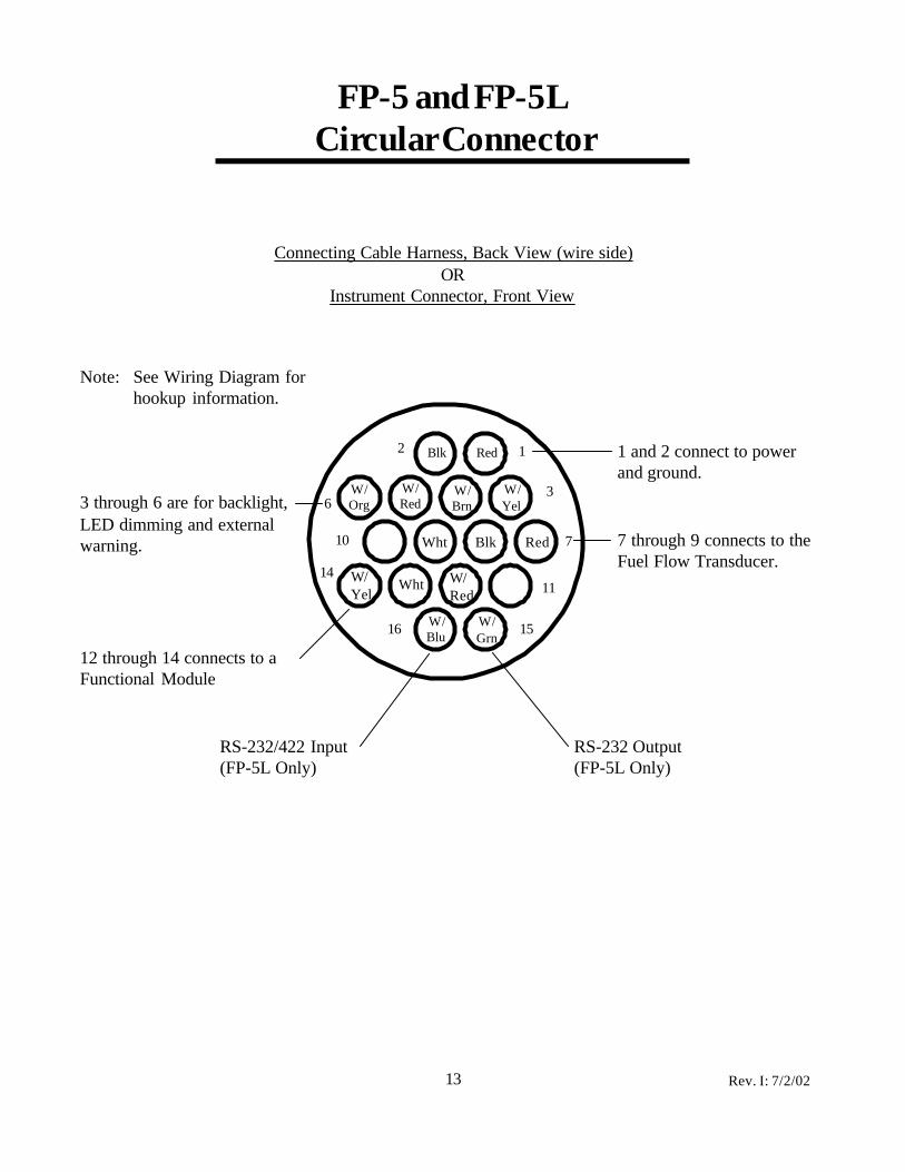
FP-5 and FP-5L Circular Connector
1 and 2 connect to powerand ground.
63
710
1114
1516
2 1Blk Red
W/Yel
W/Brn
W/Red
W/Org
W/Red
WhtW/Yel
Wht Blk Red 7 through 9 connects to theFuel Flow Transducer.
3 through 6 are for backlight,LED dimming and externalwarning.
Note: See Wiring Diagram forhookup information.
Connecting Cable Harness, Back View (wire side)OR
Instrument Connector, Front View
12 through 14 connects to aFunctional Module
W/Grn
W/Blu
RS-232 Output(FP-5L Only)
RS-232/422 Input(FP-5L Only)
Rev. I: 7/2/02

3 1
4
79
6
Connecting Cable Harness, Back View (wire side)
Module Connector, Front ViewOR
Blk Red
W/Blk
W/Red
14
FFDM-1 Circular Connector
Note: See Wiring Diagramfor hook up information. Power and Ground Wires
To Feed Transducer
To Return Transducer
Wht
W/Blk
W/RedWht
Rev. I: 7/2/02
15
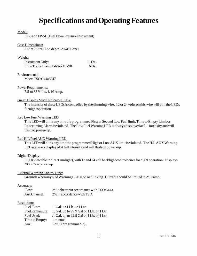
Specifications and Operating FeaturesModel:
FP-5 and FP-5L (Fuel Flow/Pressure Instrument)
Case Dimensions:2.5" x 2.5" x 3.65" depth, 2 1/4" Bezel.
Weight:Instrument Only: 11 Oz.Flow Transducer FT-60 or FT-90: 6 Oz.
Environmental:Meets TSO C44a/C47
Power Requirements:7.5 to 35 Volts, 1/10 Amp.
Green Display Mode Indicator LEDs:The intensity of these LEDs is controlled by the dimming wire. 12 or 24 volts on this wire will dim the LEDsfor night operation.
Red Low Fuel Warning LED:This LED will blink any time the programmed First or Second Low Fuel limit, Time to Empty Limit orReoccurring Alarm is violated. The Low Fuel Warning LED is always displayed at full intensity and willflash on power-up.
Red H/L Fuel AUX Warning LED:This LED will blink any time the programmed High or Low AUX limit is violated. The H/L AUX WarningLED is always displayed at full intensity and will flash on power-up.
Digital Display:LCD (viewable in direct sunlight), with 12 and 24 volt backlight control wires for night operation. Displays"8888" on power up.
External Warning Control Line:Grounds when any Red Warning LED is on or blinking. Current should be limited to 2/10 amp.
Accuracy:Flow: 2% or better in accordance with TSO C44a.Aux Channel: 2% in accordance with TSO.
Resolution:Fuel Flow: .1 Gal. or 1 Lb. or 1 Ltr.Fuel Remaining: .1 Gal. up to 99.9 Gal or 1 Lb. or 1 Ltr.Fuel Used: .1 Gal. up to 99.9 Gal or 1 Lb. or 1 Ltr.Time to Empty: 1 minuteAux: 1 or .1 (programmable).
Rev. I: 7/2/02
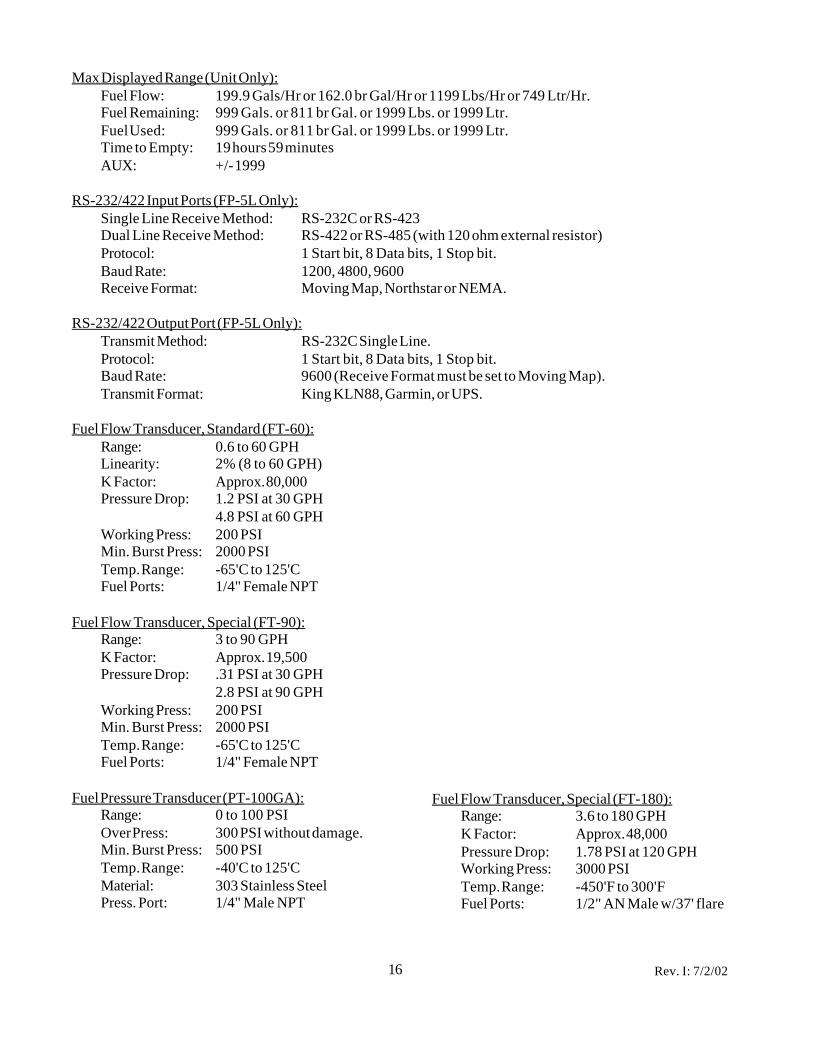
Max Displayed Range (Unit Only):Fuel Flow: 199.9 Gals/Hr or 162.0 br Gal/Hr or 1199 Lbs/Hr or 749 Ltr/Hr.Fuel Remaining: 999 Gals. or 811 br Gal. or 1999 Lbs. or 1999 Ltr.Fuel Used: 999 Gals. or 811 br Gal. or 1999 Lbs. or 1999 Ltr.Time to Empty: 19 hours 59 minutesAUX: +/- 1999
RS-232/422 Input Ports (FP-5L Only):Single Line Receive Method: RS-232C or RS-423Dual Line Receive Method: RS-422 or RS-485 (with 120 ohm external resistor)Protocol: 1 Start bit, 8 Data bits, 1 Stop bit.Baud Rate: 1200, 4800, 9600Receive Format: Moving Map, Northstar or NEMA.
RS-232/422 Output Port (FP-5L Only):Transmit Method: RS-232C Single Line.Protocol: 1 Start bit, 8 Data bits, 1 Stop bit.Baud Rate: 9600 (Receive Format must be set to Moving Map).Transmit Format: King KLN88, Garmin, or UPS.
Fuel Flow Transducer, Standard (FT-60):Range: 0.6 to 60 GPHLinearity: 2% (8 to 60 GPH)K Factor: Approx. 80,000Pressure Drop: 1.2 PSI at 30 GPH
4.8 PSI at 60 GPHWorking Press: 200 PSIMin. Burst Press: 2000 PSITemp. Range: -65'C to 125'CFuel Ports: 1/4" Female NPT
Fuel Flow Transducer, Special (FT-90):Range: 3 to 90 GPHK Factor: Approx. 19,500Pressure Drop: .31 PSI at 30 GPH
2.8 PSI at 90 GPHWorking Press: 200 PSIMin. Burst Press: 2000 PSITemp. Range: -65'C to 125'CFuel Ports: 1/4" Female NPT
Fuel Pressure Transducer (PT-100GA):Range: 0 to 100 PSIOver Press: 300 PSI without damage.Min. Burst Press: 500 PSITemp. Range: -40'C to 125'CMaterial: 303 Stainless SteelPress. Port: 1/4" Male NPT
Fuel Flow Transducer, Special (FT-180):Range: 3.6 to 180 GPHK Factor: Approx. 48,000Pressure Drop: 1.78 PSI at 120 GPHWorking Press: 3000 PSITemp. Range: -450'F to 300'FFuel Ports: 1/2" AN Male w/37' flare
16 Rev. I: 7/2/02

Drawn By: Electronics International Inc.Approved By:
Scale:
Material:
Next Assembly:
P/N: Date: Rev: D/N:12/29/93 1229931
R.R.
R.R.
None
Installation of a Fuel Flow Transducer on the Fire Wall and inthe fuel line from the fuel pump to the carburetor or fuel servo .
Note: Not applicable for a fuel injected engine with a fuelreturn line (see D/N 0415941).
D: 7/2/02
(OUT)(IN)
Fuel Flow Transducer
Bracket
To the Carburetor(or Fuel Servo)
Adapter, (1/4 NPT to Fuel Hose)Adapter, (1/4" NPT to Fuel Hose)
From the Fuel Pump(or Fuel Filter on agravity feed system).
Mounting Procedure:
1. Find a convenient location on the fire wall (away from any hot exhaust pipes) and mount abracket for the Fuel Flow Transducer. Check both sides of the fire wall for clearance beforedrilling any holes.
2. Mount the Fuel Flow Transducer onto the Bracket. You must use the FT-90 Fuel Flow Trans-ducer on a gravity feed system or for any engine over 300 H.P. The FT-90 Transducer ismarked "Model 231" on the top of the transducer. If the Transducer is mounted within 6" of anexhaust pipe, the Flow Transducer must be wrapped with Fire Sleeving.
3. Remove the fuel hose which goes from the Fuel Pump (or the Fuel Filter on a gravity feedsystem) to the Carburetor (or Fuel Servo).
4. Purchase two new hoses, one from the fuel pump (or the Fuel Filter) to the Fuel Flow Transducer(making provisions for the fuel pressure transducer as necessary) and the other from the FuelFlow Transducer to the carburetor (or Fuel Servo). There must be flexible hose in and out ofthe Transducer. The hoses must meet TSO-C53a Type C or D FAA specification. The newhoses must be the same size as the current hoses in the aircraft. A source of fittings andfabricated hoses is:
Sacramento Sky Ranch Inc.(916) 421-7672
Fax: (916) 421-5719
Varga Enterprises Inc.(602) 963-6936
FAX: (602) 899-0324OR
5. Read the Installation Instructions for important installation considerations.
17

Drawn By: Electronics International Inc.Approved By:
Scale:
Material:
Next Assembly:
P/N: Date: Rev: D/N:12/29/93
R.R.
R.R.
None
Installation of a Fuel Flow Transducer suspended in the fuelline from the fuel pump to the carburetor or fuel servo .
Note: Not applicable for a fuel injected engine with a fuelreturn line (see D/N 0415941).
(IN)(OUT)
From the Fuel Pump(or Fuel Filter on agravity feed system)
To the Carburetor(or Fuel Servo)
Fuel Flow Transducer
Adapter, (1/4" NPT to Fuel Hose) 6" Maximum fromsupport or fitting
Mounting Procedure:
1. Find a convenient location within 6" of a hose support or fitting and away from any hot exhaustpipes to suspend the Fuel Flow Transducer. The hose support or fitting may be on the input oroutput line of the Flow Transducer.
2. Remove the fuel hose which goes from the Fuel Pump (or the Fuel Fliter on a gravity feedsystem) to the Carburetor (or Fuel Servo).
3. Purchase two new hoses: one to be used from the fuel pump (or the Fuel Filter) to the Fuel FlowTransducer and the other to be used from the Fuel Flow Transducer to the carburetor (or FuelServo). There must be flexible hose in and out of the Transducer. The hoses must meet TSO-C53a Type C or D FAA specification. The new hoses must be the same size as the currenthoses in the aircraft. A source of fittings and fabricated hoses is:
4. Mount the Fuel Flow Transducer in the fuel line. You must use the FT-90 Fuel Flow Trans-ducer on a gravity feed system or for any engine over 300 H.P. The FT-90 Transducer ismarked "Model 231" on the top of the transducer. If the Transducer is mounted within 6" ofan exhaust pipe, the Flow Transducer must be wrapped with Fire Sleeving.
5. Read the Installation Instructions for important installation considerations.
Sacramento Sky Ranch Inc.(916) 421-7672
Fax: (916) 421-5719
Varga Enterprises Inc.(602) 963-6936
FAX: (602) 899-0324OR
D: 7/2/02 122993218

Drawn By: Electronics International Inc.Approved By:
Scale:
Material:
Next Assembly:
P/N: Date: Rev: D/N:10/15/94
R.R.
R.R.
None
Installation of a Fuel Flow Transducer suspended in the fuelreturn line from the carburetor to the fuel tank.
Note: Only applicable for installation on aircraft with a fuelreturn line from the Carburetor.
(IN)(OUT)
Fuel Flow Transducer
Adapter, (1/4" NPT to Fuel Hose) 6" Maximum fromsupport or fitting
Mounting Procedure:
1. Find a convenient location within 6" of a hose support or fitting and away from any hot exhaustpipes to suspend the Fuel Flow Transducer. The hose support or fitting may be on the input oroutput line of the Flow Transducer.
2. Remove the return fuel hose which goes from the Carburetor to the Fuel Tank.
3. Purchase two new hoses: one to be used from the Carburetor to the Fuel Flow Transducer andthe other to be used from the Fuel Flow Transducer to the Fuel Tank. There must be flexiblehose in and out of the Transducer. The hoses must meet TSO-C53a Type C or D FAA specifi-cation. The new hoses must be the same size as the current hose in the aircraft. A source offittings and fabricated hoses is:
1015941
To the Fuel Tank Fuel return line fromthe Carburetor
19
4. Mount the Fuel Flow Transducer in the fuel return line. You must use the FT-90 Fuel FlowTransducer on any engine that has over 300 H.P. If the Transducer is mounted within 6" ofan exhaust pipe, the Flow Transducer must be wrapped with Fire Sleeving.
5. Read the Installation Instructions for important installation considerations.
Sacramento Sky Ranch Inc.(916) 421-7672
Fax: (916) 421-5719
Varga Enterprises Inc.(602) 963-6936
FAX: (602) 899-0324OR
A: 7/2/02

Drawn By: Electronics International Inc.Approved By:
Scale:
Material:
Next Assembly:
P/N: Date: Rev: D/N:4/15/94
R. R.
R.R.
None
Installation of the Fuel Flow Transducer suspended in the fuelline between the Fuel Servo and the Flow Divider.
Note: Only applicable for installation on aircraft with a fuelreturn line from the Fuel Servio.
0415941
Mounting Procedure:
1. Find a convenient location between the Fuel Servo and FlowDivider and away from any hot exhaust pipes to suspend theFuel Flow Transducer.
2. Remove the fuel hose which goes from the Fuel Servo to theFlow Divider.
3. Purchase two new hoses: one to be used from the Fuel Servoto the Fuel Flow Transducer and the other to be used from theFuel Flow Transducer to the Flow Divider. There must beflexible hose in and out of the Fuel Transducer. The hosesmust meet TSO-C53a Type C or D FAA specification. Thenew hoses must be the same size as the current hose in theaircraft. A source of fittings and fabricated hoses is:
Adapter, (1/4" NPTto Fuel Hose)
(IN)
(OUT)
From the Fuel Servo
To the Flow Divider
Sacramento Sky Ranch Inc.(916) 421-7672
Fax: (916) 421-5719
Varga Enterprises Inc.(602) 963-6936
FAX: (602) 899-0324OR
4. Mount the Fuel Flow Transducer in the fuel line. You must use the FT-90 Fuel Flow Trans-ducer on any engine over 300 H.P. If the Transducer is mounted within 6" of an exhaustpipe, the Flow Transducer must be wrapped with Fire Sleeving.
5. Read the Installation Instructions for important installation considerations.
20 B: 7/2/02