fuel cells, gasifier, fischer- thsthidtropsch synthesis
TRANSCRIPT

Fuel Cells, Gasifier, Fischer-T h S th i dTropsch Synthesis and
Energy ParkEnergy Park
Preparation for study trip to the CUTEC-Institute
1 2nd of November 2009

Current utilization of biomass
2 2nd of November 2009

Fuel cells - basics
• Principle known since 1838Electro chemical combustion“• Electro chemical „combustion“ separated by an electrolyte
• Example of a proton exchanging l lelectrolyte
• Also oxygen ions exchanging electrolytes
• Basic construction: anode, electrolytes and cathode
• These three parts can consist of• These three parts can consist of different materials depending of the fuel cell type
3 2nd of November 2009

Fuel cells - basics
Advantages• High efficiency• No emissions (NOx SO2 CO)
Disadvantages• Cleanness of fuel required• Technology still under R&D• No emissions (NOx, SO2, CO)
• Low abrasion • Low vibrations and silent
• Technology still under R&D• High costs and low lifespan
4 2nd of November 2009
• Good scalability of power

Fuel cells - basics• under normal conditions (25 °C, 1 bar) only 1,23 Volt• to less for a technical application but voltage can be increasedto less for a technical application, but voltage can be increased
by a serial connection of single elements so-called „stacks“
5 2nd of November 2009
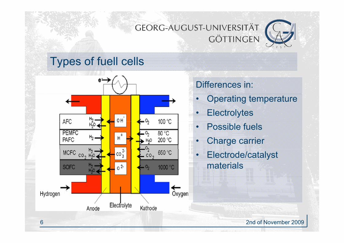
Types of fuell cellsyp
Differences in:• Operating temperature• Electrolytes• Possible fuels• Charge carrier• Electrode/catalyst
materials
6 2nd of November 2009
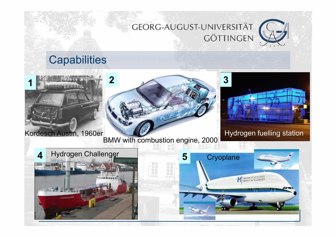
Capabilitiesp
1 32
Kordesch Austin, 1960er Hydrogen fuelling stationBMW with combustion engine, 2000
5 Cryoplane4 Hydrogen Challenger
7 2nd of November 2009
Resumé
Fuel cells allow an electricity generation with:• high electrical efficiency• Possibility of waste heat utilisation• Renewable fuels
Challenge• Cost reduction• Increase of lifespan• Demonstration of suitability for daily use
8 2nd of November 2009
Demonstration of suitability for daily use

Gasifier:
Definitions:
Combustion: Pyrolysis:Gasification:• λ ≥ 1 • exothermal
• λ = 0• endothermal
• 0 < λ < 1 • endothermal /
th l• excess oxygen with air, pure 02
• oxygen exclusion
exothermal • oxygen
deficiency withdeficiency with air, pure O2, steam
9 2nd of November 2009

Sub processes of the gasificationp g
ReductionOxidationPyrolysisHeating and Drying
800-1100 °C500-2000 °C150-500 °C100-200 °C
y g
steam
productvolatilepyrolytic
Biomass waste gasproduct
gasdryBiomass
carbon
pyrolyticproducts
heat inputoxygen inputheat inputheat input
carbon
10 2nd of November 2009
heat inputoxygen inputheat inputheat inputRefernce: Kaltschmidt, Hartmann

Chemical reactions of the gasificationg
Gas/Solids-ReactionsPartial combustion C + O ↔ CO 123 kJ/molPartial combustion C + O2 ↔ CO2 - 123 kJ/molHeterogeneous water gas reaction C + H2O ↔ CO+ H2 +119 kJ/molreaction C + H2O ↔ CO+ H2 +119 kJ/molBoudouard-Reaction C + CO2 ↔ 2CO +162 kJ/molHydrogenated yd oge atedgasification C + 2 H2 ↔ CH4 - 87 kJ/mol
Gas/Gas-ReactionsWGS-Reaction CO + H2O ↔ CO2 + H2 - 41 kJ/mol
11 2nd of November 2009
Methanation CO + 3H2 ↔ CH4 + H2O -206 kJ/mol

Dryingy g
Evaporation of the water, which is included in the biomass• Temperatures until 200°C• Water vapour is transformed in the following water
gas reaction • No chemical transformation of the biomass• Transformation of the structure of the material by Transformation of the structure of the material by
macro- and microscopical cracks
12 2nd of November 2009

PyrolysisDecomposition of the organic macromolecules• Temperatures are dependent on
the process: 200-500 °CD i i f• Determinative factors: – Temperature
Rate of heating– Rate of heating– Dimension of the fuel particle
• Tar creation up to 280 °CTar creation up to 280 C • 350-400 °C creation capacity on its
peak
13 2nd of November 2009
• Tar concentration in the pyrolyses on its peak

Oxidation
Oxidation of the carbon and the water vapour for covering of the heat demandheat demand
• exothermal reactions, temperatures between 500 and 2000°C• Heat producing for the endothermal reactions and heat loss of
the reactor• Combustion of only a part of the biomassCombustion of only a part of the biomass• Important reactions:
C + O2 → CO2 ∆H = -393,5 kJ/molC + ½ O2 ↔ CO ∆H = -123,1 kJ/molH2 + ½ O2 ↔ H2O ∆H = - 68,3 kJ/mol
14 2nd of November 2009
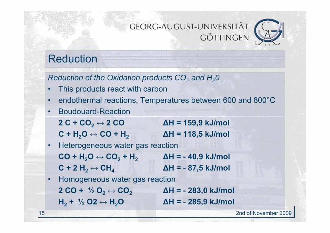
Reduction Reduction of the Oxidation products CO2 and H20• This products react with carbonThis products react with carbon• endothermal reactions, Temperatures between 600 and 800°C• Boudouard-Reaction
2 C + CO2 ↔ 2 CO ∆H = 159,9 kJ/molC + H2O ↔ CO + H2 ∆H = 118,5 kJ/molH t t ti• Heterogeneous water gas reaction CO + H2O ↔ CO2 + H2 ∆H = - 40,9 kJ/molC + 2 H2 ↔ CH4 ∆H = - 87 5 kJ/molC + 2 H2 ↔ CH4 ∆H 87,5 kJ/mol
• Homogeneous water gas reaction2 CO + ½ O2 ↔ CO2 ∆H = - 283,0 kJ/mol
15 2nd of November 2009
H2 + ½ O2 ↔ H2O ∆H = - 285,9 kJ/mol

Gasification processesp
mitt
, 200
1re
nce:
Kal
tsch
m
16 2nd of November 2009
Ref
er
Functionality Fluidized bed reactory
• Bed material: mostly quartz sand• Fluidized bed: the fumigator flows through the reactor disperses the• Fluidized bed: the fumigator flows through the reactor, disperses the
interior bed material and circulates around the combustible• Mixture of the combustible particles with themselves and with the bed p
material• No distinctive temperature and reactions zones• Constant temperatures between 700 and 900 °C• Differantiation between following process techniques:
Stationary fluidized bed reactor– Stationary fluidized bed reactor – Circulating fluidized bed reactor– Combination of more than one fluidized beds
17 2nd of November 2009
– Combination of more than one fluidized beds

CUTEC-Gasifier
Circulating fluidized bed reactor
• Constant temperature distribution• Good interior heat transfer
Easy technology no moving• Easy technology, no moving particles
• Security, high availability, stable processprocess
• Reduced tar formation during gasification of water vapourC t t lit b f• Constant gas quality because of constant conditions in the reactor
• Stationary fluidized bed possible
18 2nd of November 2009
• Good Scale-Up possibilities

Fluidized bed reactor
Advantages• Heterogeneous and difficult combustibles can be
used• Long resistance time of the solid matters• Robust system operation
Disadvantagesg• High tar concentration in the product gas• Heat transfer very complex
19 2nd of November 2009
Heat transfer very complex

Utilization of the gasg
G ifiGas
Gas turbineEngine
G f f
Gasifier purification Fuel CellSteam process
Gas purification necessary because of:1. Particle burden2. Tar content3. Residual components (NH3, H2S, COS, Alkalis)
Primary arrangements: Modification of the gasifier Secondary arrangements: Secondary arrangements:
• Hot gas filter, cyclone, E-trap• Scrubber
20 2nd of November 2009
• Catalysts, e.g. nickel• Dolomite as cracker

Fischer-Tropsch Synthesep y
• 1925 developed by Fischer and Tropsch1934 th fi t ti d i l l• 1934 the first time used in a large scale
• Transformation of synthesis gas (CO, H2) into carbon hydrideshydrides– Temperatures between 200°C and 400°C– Pressure between 20bar and 40bar– Special catalysts
• Intention: production of von synthetic fuels (XtL)• Basic material: Residual biomass (straw, wooden
residuals, ...)
21 2nd of November 2009
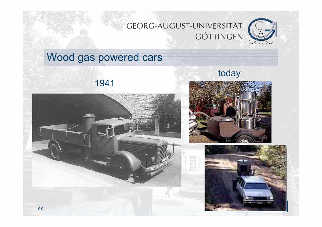
Wood gas powered carsg p
1941today
22 2nd of November 2009

Requirements on renewable fuelsq
• Low exhaust gas emission (CO, NOx, HC etc.)• Good combustion• High energy density• Low residues• Resistance to corrosion• Secure manageability• Acceptable costs• Use of the petrol station infrastructure• Compatibility to conventional fuels
23 2nd of November 2009

Desired reactions
Fischer-Tropsch reactionsCO 2 H ( CH ) H O ∆H 159 kJ/ lCO+2 H2 ↔ (-CH2-)+H2O ∆H = -159 kJ/mol2 CO+H2 ↔ (-CH2-)+CO2 ∆H = -198 kJ/mol
Water gas conversionCO+H O ↔ CO +H ∆H = -40 kJ/molCO+H2O ↔ CO2+H2 ∆H = -40 kJ/mol
Others possible reactionsOthers possible reactions3 CO+H2O ↔ (-CH2-)+2 CO2 ∆H = -238 kJ/molCO2+3 H2 ↔ (-CH2-)+2 H2O ∆H = -119 kJ/mol
24 2nd of November 2009
2 2 ( 2 ) 2

Fischer-Tropsch-CUTEC pilot installationp p
25 2nd of November 2009

Practical Example: Sun fuel (Choren)p ( )
Out of 1 ton wood isOut of 1 ton wood is produced 100 l Sunfuel
Optimization for the future:future:210 l Sunfuel / t wood
AG
ence
: Vol
ksw
agen
A
26 2nd of November 2009
Ref
ere
Advantages and disadvantages of FTS-Dieselg gAdvantages:• Colour- and odourless, low toxicity• Reduction of defect components during the combustion• Fuels offered in the petrol station net• No loss of engine power• No loss of engine power• Possible use as airplane fuel• Mixable with conventional Diesel in every ratio• Synthetic fuels can be adopted to the desires of the engine
manufacturers
Disadvantages:Disadvantages:• Bad cooling capacities• Low flashpoint
27 2nd of November 2009
• Complex process

CUTEC Project: Energy Park in Clausthalj gy
• Complete supply of the block of buildings• Completely of renewable resources• Interconnection of relevant energy conversion processes• Combination of non influenceable components with
controllable componentsR ti i d i ll ti t (i d )• Reporting in dynamic small time segments (in seconds)
• Operation in isolated network
28 2nd of November 2009

Overview Energy park Clausthalgy p
29 2nd of November 2009

Integrated energy resourcesg gyThermal use of wood chips
Biogas engine-cogeneration unit
PV-plant
30 2nd of November 2009PPO-engine-cogeneration unit