ftth - fibre to the home - ies ftth-fibre...cabling solutions ftth - fibre to the home cutting-edge...
TRANSCRIPT

Cabling Solutions
FTTH - Fibre To THe HomeCutting-edge total solutions for superfast fibre-optic broadband networks
Our website will always keep you updated on:
One click worth your while!
www.daetwyler-cables.com
www.daetwyler-cables.com
Product and system news
Current events
Newsletter – Register now!
References
Technical documentation
�
Cent
ral O
ffice
/PoP
Solu
tions
Cabl
ing
Solu
tions
In-h
ouse
Cabl
ing
Solu
tions
Man
agem
ent S
oftw
are S
olut
ion
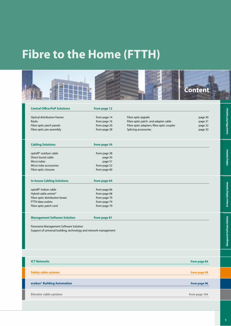
Central Office/PoP Solutions from page �2
Optical distribution frames from page 14Racks from page 16Fibre optic patch panels from page 20Fibre optic pre-assembly from page 28
Cabling Solutions from page 34
optofil® outdoor cable from page 38Direct-burial cable page 50Micro tubes page 51Micro tube accessories from page 52Fibre optic closures from page 60
In-house Cabling Solutions from page 64
optofil® indoor cable from page 66Hybrid cable uninet® from page 68Fibre optic distribution boxes from page 70FTTH data outlets from page 74Fibre optic patch cord from page 79
Management Software Solution from page 8�
Panorama Management Software SolutionSupport of universal building, technology and network management
Fibre to the Home (FTTH)
Fibre optic pigtails page 30Fibre optic patch- and adapter cable page 31Fibre optic adapters, fibre optic coupler page 32Splicing accessories page 33
Content
ICT Networks from page 84
Safety cable systems from page 90
Elevator cable systems from page �04
ecobus® Building Automation from page 96
2
Cent
ral O
ffice
/PoP
Solu
tions
Cabl
ing
Solu
tions
In-h
ouse
Cabl
ing
Solu
tions
Man
agem
ent S
oftw
are S
olut
ion
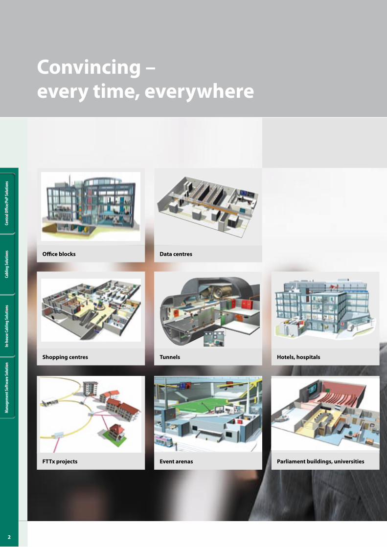
Event arenas
Tunnels
Parliament buildings, universitiesFTTx projects
Data centresOffice blocks
Shopping centres Hotels, hospitals
Convincing – every time, everywhere

3
Cent
ral O
ffice
/PoP
Solu
tions
Cabl
ing
Solu
tions
In-h
ouse
Cabl
ing
Solu
tions
Man
agem
ent S
oftw
are S
olut
ion
The life blood of a modern public or commercial buildings is the functionality and reliability of the system solutions for communications, building au-tomation, power supply, safety and lifts. This is true of any such construction, irrespective of whether it is an office block, hotel, sports stadium, television studio or a tunnel. Choose a reliable system partner right from the start.
Choose Datwyler!
Datwyler is a highly regarded company about to ce-lebrate its 100th year of operation. With the backing of a financially powerful group, Datwyler operates on the international stage as a successful supplier of total solutions for the electrical and communications infrastructure of buildings and for FTTx networks. We lead the way in innovations for applications such as information and communications technology, power supply and safety, building automation and lifts.
Our systems are reliable and constitute a secure in-vestment on your part. This is all thanks to the years of experience and proven expertise of our engineers and technicians. Datwyler is a one-stop source of customised solutions for all your specific applications – as attractive total solutions, with all the necessary test certificates, authorisations and certificates and with long-term warranties.
Our workforce prides itself on delivering a full package of services for all the products and solutions supplied by the company. You can rely on our expert support for all aspects of our supply – beginning with planning, consultancy, through pre-assembly, logistics, installa-tion and ending with system maintenance.
A reliable partner at your side

4
Cent
ral O
ffice
/PoP
Solu
tions
Cabl
ing
Solu
tions
In-h
ouse
Cabl
ing
Solu
tions
Man
agem
ent S
oftw
are S
olut
ion
Turnkey installations
Advice
Mai
nten
ance
Implementation
Planning
Electrical and communications
infrastructure
Com
munication
EnergyBuilding auto
mat
ion
Safety Datwyler does not only supply in-tegrated total solutions, but has positioned itself successfully as a turnkey partner: for all manner of purpose-built constructions inclu-ding multi-site projects and for FTTx projects. Our successful processing
of turnkey projects derives from our high-level skills in developing and
manufacturing the required products and solutions, our comprehensive ap-
plications expertise and the international scope of Datwyler activities.
Our international presence and our world-wide, actively managed and certificated partner network have also proved invaluable in the multi-site projects of major clients. National and international companies rely on Datwyler on-the-spot site audits. Using the site audits as a base, our engineering experts work out customised solutions with uniform standards for all the sites concerned. Our total solutions package is rounded off by the implementation and assurance of regular operations. While operations are running, we provide servicing and maintenance work to optimise your infrastructure solution. These MAC (move, add, change) services increase the performance and working life of your equipment.

�
Cent
ral O
ffice
/PoP
Solu
tions
Cabl
ing
Solu
tions
In-h
ouse
Cabl
ing
Solu
tions
Man
agem
ent S
oftw
are S
olut
ion
Worldwide expertise in turnkey creation, multi-site projects and services
High-quality solutions for all your applicationsYear on year, Datwyler invests in even better materials and process technologies, production resources and test methods. This is why our system solutions always keep ahead of the current norms and repeatedly set new standards. The important functions which our solutions must deliver in practice demand the highest possible level of safety and reliability. This is why we measure each product against stringent quality stan-dards before it leaves the company. Of course, all our processes are ISO 9000-2001/14001 certified.
Opt for sustainable solutions that provide you with high-level operational reliability coupled with low operating costs. The proof that Datwyler systems can deliver these benefits has been evident for many years in thousands of installations around the world. In addition, we have a particularly keen eye for con-sistent, intelligent solutions that simplify planning, sourcing and installation and shorten your construc-tion times.
We have the right total solutions for all your appli-cations, whatever they are – high-speed commu-nications networks, modern energy distribution, monitoring and control duties, fire alarm systems or lift cabling. Or you may want to integrate new systems, interconnect and automate existing systems or simply ensure a reliable power supply. All this is possible with our carefully thought out, pre-assembled and prefabricated subsystems.
Just tell us how, when and whereBesides quality and product price, the logistics per-formance capability of suppliers is a decisive factor in the successful handling of construction projects. This is particularly true of major projects. With its years of experience and high logistics competences, Datwyler can handle even time-critical major projects smoothly and to the complete satisfaction of customers. Just-in-time deliveries at the right place are all in a day’s work for us and our partners.
Besides delivering straight to the construction site, we also offer you additional logistics services (time slots, pre-fitted and pre-assembled products etc.). Many cu-stomers and suppliers have a direct link to our IT system for rapid and flexible order processing.
As regards cable pre-assembly, Datwyler also has wide-ranging expertise, the product of decades of experience. In our modern cable cutting centre, the engineering department passes the cutting orders electronically without any media discontinuity straight to the production area. Our efficient order communi-cation system with all our customers is due to years of experience with B2B interfaces.
In the growth markets of Eastern Europe and the Middle East, and in many other countries as well, Datwyler works in close co-operation with independent distri-bution partners. Customers can rely on the consistently high quality standard of all Datwyler products and solutions whilst benefiting from local contacts and logistics services.
We support you in realising your infrastructure project – reliably, capably, complete and with the highest quality!

6
Cent
ral O
ffice
/PoP
Solu
tions
Cabl
ing
Solu
tions
In-h
ouse
Cabl
ing
Solu
tions
Man
agem
ent S
oftw
are S
olut
ion
The last infrastructure revolution in telecommunications
Colocation (Telehouse)
City networks
Access network / Fibre to the Building
Fiber to the Home (FTTH)

�
Cent
ral O
ffice
/PoP
Solu
tions
Cabl
ing
Solu
tions
In-h
ouse
Cabl
ing
Solu
tions
Man
agem
ent S
oftw
are S
olut
ion
Over the last ten years, demand for bandwidth and the accompanying expansion of bandwidth in industrialised countries has increased ten-fold. The move from tradi-tional, analogue TV consumption to individual digital television, Video on Demand, online gaming and Voice over IP means that copper is gradually approaching its physical capacity limits over the last mile. Glass will replace copper over the last mile – this is being called the ‘last infrastructure revolution in telecoms’.
Interest in Fibre to the Home (FTTH) projects has therefore grown steadily both in Europe and worldwide. Prominent flagship cities are Amsterdam, Västerås, Vienna and Zurich. Due to the great complexity and multi-dimensional nature of FTTH projects during the planning, implementation and operating phases, the companies involved must have in-depth expertise in a wide range of disciplines including the business management, legal and technical fields. Great attention must be paid to the development of business cases in order to ensure that investors enjoy long-term financial success.
In many countries, energy supply companies and local utility companies have a crucial part to play in FTTH projects. They are the companies with access to the basic infrastructure which must be used if the high investments are to be kept within reasonable bounds. In addition to this, topics such as Smart Metering and Smart Grid are becoming increasingly important to both groups. It is relatively easy to integrate these technologies during FTTH installation.
Fibre to the Home (FTTH)
8
Cent
ral O
ffice
/PoP
Solu
tions
Cabl
ing
Solu
tions
In-h
ouse
Cabl
ing
Solu
tions
Man
agem
ent S
oftw
are S
olut
ion
• ’Reeling in‘ the building owner, including building acquisition
• Drafting of contracts with service providers and end customers
• Conceptual network design, in-house/outdoor • Survey of the existing infrastructure (routes, pipes,
building connections, etc.)• Availability of expertise, resources and organisation• Establishing and evaluating business and operation
support systems (BSS/OSS)• Carrying out a pilot/reference project• Process optimisation, eliminating work stages, cost
optimisation• Roll-out in the planned area• Maintenance and servicing of the FTTH infrastructure
The FTTH network provider will face a wide range of challenges which will vary according to the strategy selected. For example, there is the question of whether the company itself should provide a service to cu-stomers, including triple play services, or make the infrastructure (optical distribution network) available to one service provider or several.
The aspects listed clearly indicate that a large number of disciplines are involved in an FTTH project.
The core elements of successful FTTH projects are: • Business model and business plan • Service portfolio• Collaboration with telecoms service providers
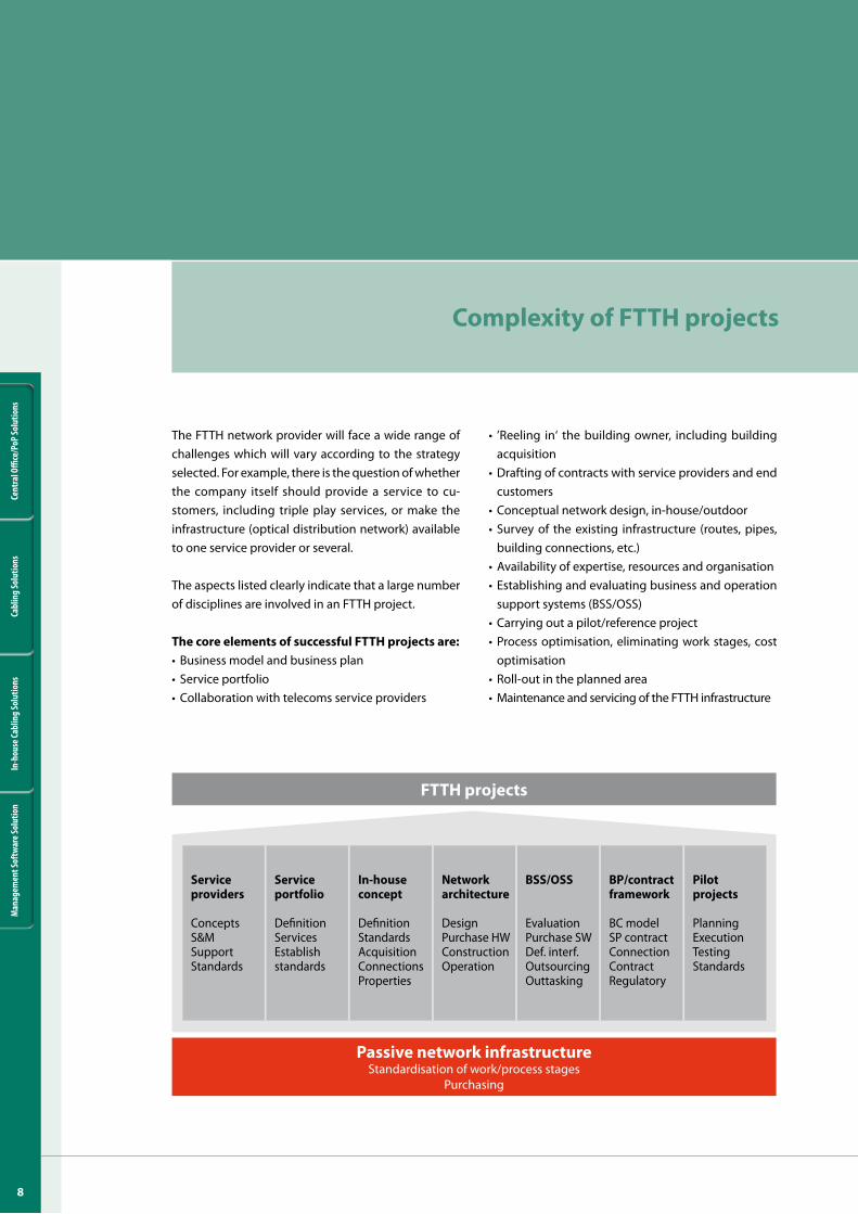
Passive network infrastructureStandardisation of work/process stages
Purchasing
FTTH projects
Service providers
ConceptsS&MSupportStandards
Service portfolio
DefinitionServicesEstablishstandards
In-house concept
DefinitionStandardsAcquisitionConnectionsProperties
Network architecture
DesignPurchase HWConstructionOperation
BSS/OSS
EvaluationPurchase SWDef. interf.OutsourcingOuttasking
BP/contract framework
BC modelSP contractConnectionContractRegulatory
Pilot projects
PlanningExecutionTestingStandards
Complexity of FTTH projects
9
Cent
ral O
ffice
/PoP
Solu
tions
Cabl
ing
Solu
tions
In-h
ouse
Cabl
ing
Solu
tions
Man
agem
ent S
oftw
are S
olut
ion
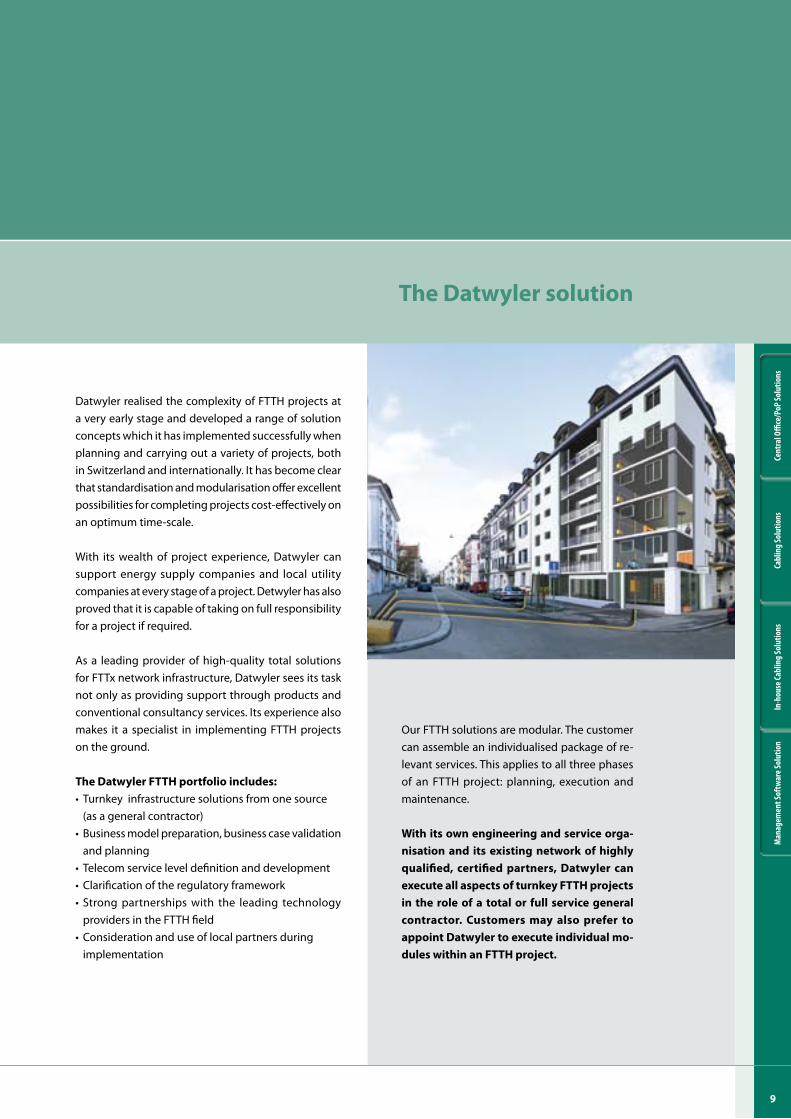
Our FTTH solutions are modular. The customer can assemble an individualised package of re-levant services. This applies to all three phases of an FTTH project: planning, execution and maintenance.
With its own engineering and service orga-nisation and its existing network of highly qualified, certified partners, Datwyler can execute all aspects of turnkey FTTH projects in the role of a total or full service general contractor. Customers may also prefer to appoint Datwyler to execute individual mo-dules within an FTTH project.
Datwyler realised the complexity of FTTH projects at a very early stage and developed a range of solution concepts which it has implemented successfully when planning and carrying out a variety of projects, both in Switzerland and internationally. It has become clear that standardisation and modularisation offer excellent possibilities for completing projects cost-effectively on an optimum time-scale.
With its wealth of project experience, Datwyler can support energy supply companies and local utility companies at every stage of a project. Detwyler has also proved that it is capable of taking on full responsibility for a project if required.
As a leading provider of high-quality total solutions for FTTx network infrastructure, Datwyler sees its task not only as providing support through products and conventional consultancy services. Its experience also makes it a specialist in implementing FTTH projects on the ground.
The Datwyler FTTH portfolio includes:• Turnkey infrastructure solutions from one source (as a general contractor)• Business model preparation, business case validation
and planning• Telecom service level definition and development• Clarification of the regulatory framework• Strong partnerships with the leading technology
providers in the FTTH field• Consideration and use of local partners during implementation
The Datwyler solution
�0
Cent
ral O
ffice
/PoP
Solu
tions
Cabl
ing
Solu
tions
In-h
ouse
Cabl
ing
Solu
tions
Man
agem
ent S
oftw
are S
olut
ion
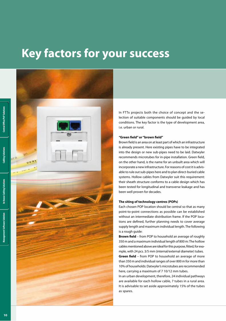
In FTTx projects both the choice of concept and the se-lection of suitable components should be guided by local conditions. The key factor is the type of development area, i.e. urban or rural.
“Green field” or “brown field”Brown field is an area on at least part of which an infrastructure is already present. Here existing pipes have to be integrated into the design or new sub-pipes need to be laid. Datwyler recommends microtubes for in-pipe installation. Green field, on the other hand, is the name for an unbuilt area which will incorporate a new infrastructure. For reasons of cost it is advis-able to rule out sub-pipes here and to plan direct-buried cable systems. Hollow cables from Datwyler suit this requirement: their sheath structure conforms to a cable design which has been tested for longitudinal and transverse leakage and has been well proven for decades.
The siting of technology centres (POPs)Each chosen POP location should be central so that as many point-to-point connections as possible can be established without an intermediate distribution frame. If the POP loca-tions are defined, further planning needs to cover average supply length and maximum individual length. The following is a rough guide:Brown field – from POP to household an average of roughly 350 m and a maximum individual length of 800 m: The hollow cables mentioned above are ideal for this purpose, fitted, for exa-mple, with 24 pcs. 3/5 mm (internal/external diameter) tubes.Green field – from POP to household an average of more than 350 m and individual ranges of over 800 m for more than 10% of households: Datwyler’s microtubes are recommended here, carrying a maximum of 7 10/12 mm tubes.In an urban development, therefore, 24 individual pathways are available for each hollow cable, 7 tubes in a rural area. It is advisable to set aside approximately 15% of the tubes as spares.
Key factors for your success
��
Cent
ral O
ffice
/PoP
Solu
tions
Cabl
ing
Solu
tions
In-h
ouse
Cabl
ing
Solu
tions
Man
agem
ent S
oftw
are S
olut
ion
The right concept, the right products and an experienced partner by your side
mination. A gas-tight connector can be integrated with each distributor. For house-front mounting we also supply solutions which can be customised to suit any given situation.
Residential cablingAs a rule a new building incorporates a viable, mo-dern standard-compliant star-shaped hollow pipe installation. In older buildings, however, one often has to contend with a tightly dimensioned pipe infrastructure generally laid in a daisy-chain confi-guration, if not a surface-mounted installation. For all these requirements Datwyler can supply special modular products which are hard-wearing enough for heavy-duty residential use.
Among others these include our flush- and surface-mountable hybrid socket, which can be fitted as a modular component, and thin in-house cables with bend-optimised fibres which are ideal for installing in ducts and pipes. Where customer end devices need to be connected with patch cables we sup-ply steel-reinforced OWG patch cables which will withstand heavy loads and have a predetermined breaking point designed to give if you trip over them, thus preventing injury or damage.
Cell division (cluster creation)Household tube allocations are drawn up at the plan-ning stage. Thus, for example, a trunk cable is planned for every 20 households (24 individual pathways, of which 4 are reserves). All the hollow microcables run to the POP and are logically numbered. Distribution closures are installed as tube distributors. Y-diverters and distribution closures from Datwyler are ideal for this purpose: connectors are used to provide individual tubes with a pressure-resistant joint (10 bar).
The ODF (Optical Distribution Frame)The choice of an ODF depends on your concept, the anticipated packing density and take-rate (subscribers = active ports). In an urban development each of the 20 individual tubes may carry up to 12 fibres. In a rural development 6 individual tubes (1 = reserve) may carry 144 fibres each. An ODF of considerable size may therefore be required! Selection of the right compo-nents depends on fibre concept and quantity. ODFs, unilan® racks and distribution panels from Datwyler are an excellent choice for all these requirements.
Household terminationDatwyler’s FTTx household distributors were spe-cially developed for passive OWG household ter-
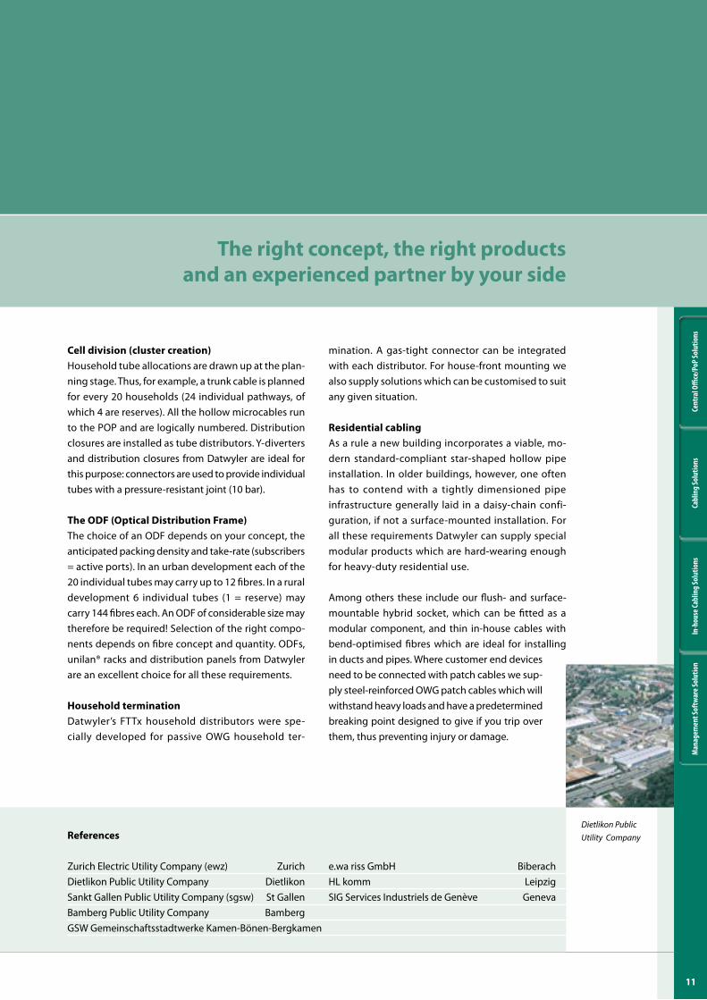
References
Zurich Electric Utility Company (ewz) Zurich e.wa riss GmbH BiberachDietlikon Public Utility Company Dietlikon HL komm LeipzigSankt Gallen Public Utility Company (sgsw) St Gallen SIG Services Industriels de Genève GenevaBamberg Public Utility Company BambergGSW Gemeinschaftsstadtwerke Kamen-Bönen-Bergkamen
Dietlikon Public Utility Company

�2
Cent
ral O
ffice
/PoP
Solu
tions
Cabl
ing
Solu
tions
In-h
ouse
Cabl
ing
Solu
tions
Man
agem
ent S
oftw
are S
olut
ion
Subject to technical modification.
unilan® patch panel OV-AFibre optic patch panel 19‘‘ 1 USplice boxpage 20
Central Office / PoP Solutions
�3
Cent
ral O
ffice
/PoP
Solu
tions
Cabl
ing
Solu
tions
In-h
ouse
Cabl
ing
Solu
tions
Man
agem
ent S
oftw
are S
olut
ion
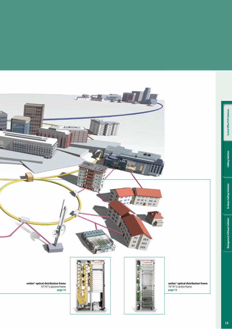
unilan® optical distribution frame19‘‘/47 U passive frame
page �4
unilan® optical distribution frame19‘‘/47 U active framepage ��
�4
Cent
ral O
ffice
/PoP
Solu
tions
Cabl
ing
Solu
tions
In-h
ouse
Cabl
ing
Solu
tions
Man
agem
ent S
oftw
are S
olut
ion
Com
mun
icat
ion
tech
nolo
gy
Product information
Subject to technical modification.
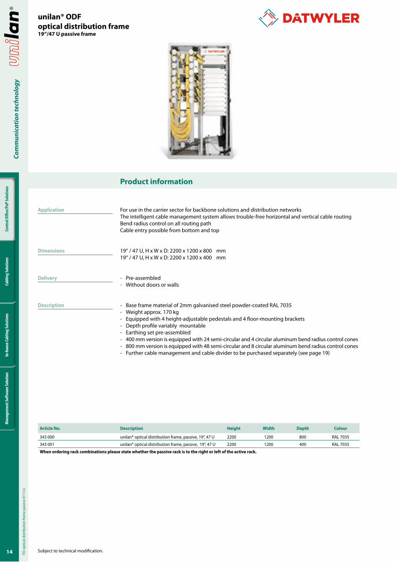
For use in the carrier sector for backbone solutions and distribution networksThe intelligent cable management system allows trouble-free horizontal and vertical cable routingBend radius control on all routing pathCable entry possible from bottom and top
19‘‘ / 47 U, H x W x D: 2200 x 1200 x 800 mm19‘‘ / 47 U, H x W x D: 2200 x 1200 x 400 mm
- Pre-assembled- Without doors or walls
- Base frame material of 2mm galvanised steel powder-coated RAL 7035- Weight approx. 170 kg- Equipped with 4 height-adjustable pedestals and 4 floor-mounting brackets- Depth profile variably mountable- Earthing set pre-assembled- 400 mm version is equipped with 24 semi-circular and 4 circular aluminum bend radius control cones- 800 mm version is equipped with 48 semi-circular and 8 circular aluminum bend radius control cones- Further cable management and cable divider to be purchased separately (see page 19)
unilan® ODFoptical distribution frame�9‘‘/4� U passive frame
Article No. Description Height Width Depth Colour
343 000 unilan® optical distribution frame, passive, 19‘‘, 47 U 2200 1200 800 RAL 7035
343 001 unilan® optical distribution frame, passive, 19‘‘, 47 U 2200 1200 400 RAL 7035
When ordering rack combinations please state whether the passive rack is to the right or left of the active rack.
FO-o
ptic
al d
istrib
utio
n fra
me
pass
ive
0111
/e
Application
Dimensions
Delivery
Description
��
Cent
ral O
ffice
/PoP
Solu
tions
Cabl
ing
Solu
tions
In-h
ouse
Cabl
ing
Solu
tions
Man
agem
ent S
oftw
are S
olut
ion
Com
mun
icat
ion
tech
nolo
gy
Product information
Subject to technical modification.
FO-o
ptic
al d
istrib
utio
n fra
me
aktiv
e 01
11/e
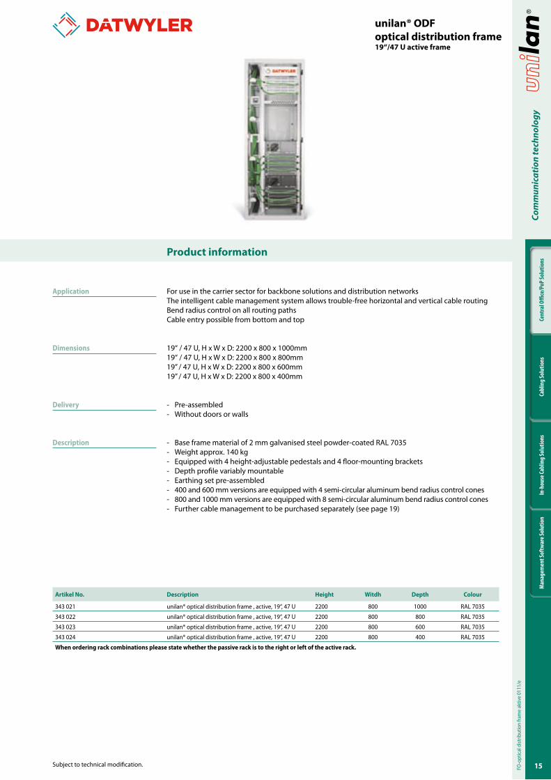
For use in the carrier sector for backbone solutions and distribution networksThe intelligent cable management system allows trouble-free horizontal and vertical cable routingBend radius control on all routing pathsCable entry possible from bottom and top
19‘‘ / 47 U, H x W x D: 2200 x 800 x 1000mm19‘‘ / 47 U, H x W x D: 2200 x 800 x 800mm19’’ / 47 U, H x W x D: 2200 x 800 x 600mm19’’ / 47 U, H x W x D: 2200 x 800 x 400mm
- Pre-assembled- Without doors or walls
- Base frame material of 2 mm galvanised steel powder-coated RAL 7035- Weight approx. 140 kg- Equipped with 4 height-adjustable pedestals and 4 floor-mounting brackets- Depth profile variably mountable- Earthing set pre-assembled- 400 and 600 mm versions are equipped with 4 semi-circular aluminum bend radius control cones- 800 and 1000 mm versions are equipped with 8 semi-circular aluminum bend radius control cones- Further cable management to be purchased separately (see page 19)
unilan® ODFoptical distribution frame�9‘‘/4� U active frame
Artikel No. Description Height Witdh Depth Colour
343 021 unilan® optical distribution frame , active, 19‘‘, 47 U 2200 800 1000 RAL 7035
343 022 unilan® optical distribution frame , active, 19‘‘, 47 U 2200 800 800 RAL 7035
343 023 unilan® optical distribution frame , active, 19‘‘, 47 U 2200 800 600 RAL 7035
343 024 unilan® optical distribution frame , active, 19‘‘, 47 U 2200 800 400 RAL 7035
When ordering rack combinations please state whether the passive rack is to the right or left of the active rack.
Application
Dimensions
Delivery
Description
�6
Cent
ral O
ffice
/PoP
Solu
tions
Cabl
ing
Solu
tions
In-h
ouse
Cabl
ing
Solu
tions
Man
agem
ent S
oftw
are S
olut
ion
Com
mun
icat
ion
tech
nolo
gy
Product information
Subject to technical modification.
Application
Dimensions
Delivery
Description
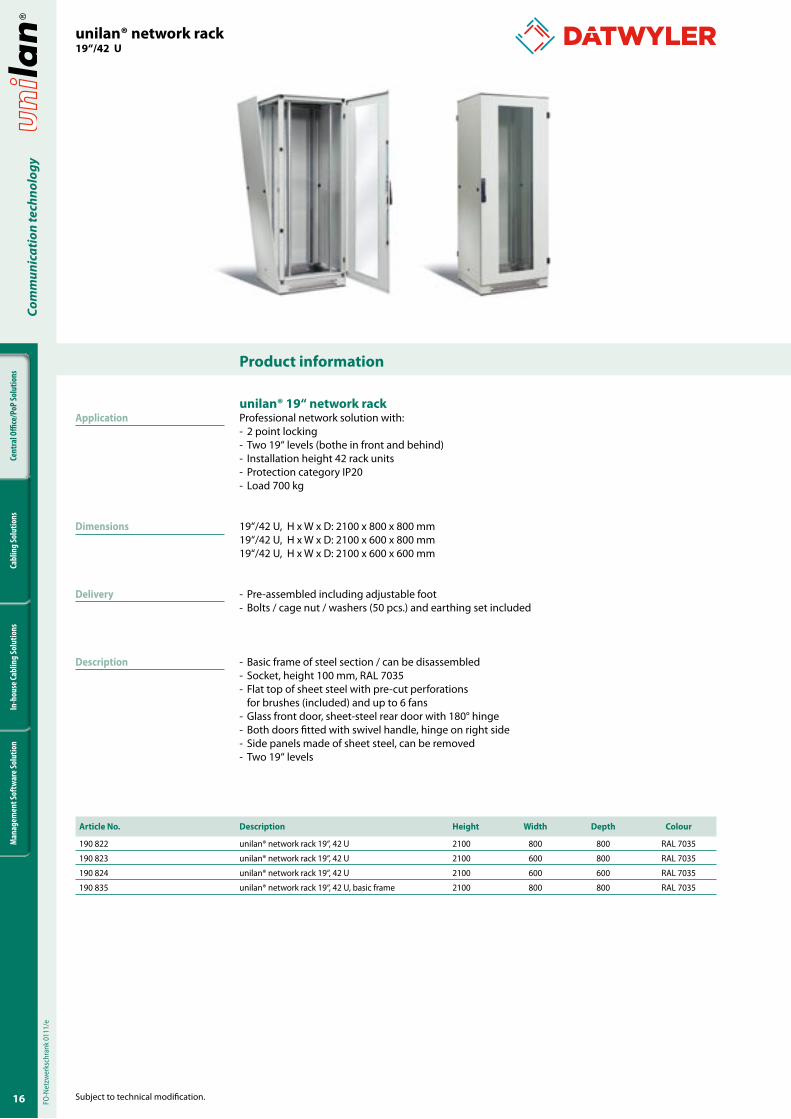
unilan® �9‘‘ network rackProfessional network solution with:- 2 point locking- Two 19“ levels (bothe in front and behind)- Installation height 42 rack units- Protection category IP20- Load 700 kg
19‘‘/42 U, H x W x D: 2100 x 800 x 800 mm19‘‘/42 U, H x W x D: 2100 x 600 x 800 mm19‘‘/42 U, H x W x D: 2100 x 600 x 600 mm
- Pre-assembled including adjustable foot- Bolts / cage nut / washers (50 pcs.) and earthing set included
- Basic frame of steel section / can be disassembled- Socket, height 100 mm, RAL 7035- Flat top of sheet steel with pre-cut perforations for brushes (included) and up to 6 fans- Glass front door, sheet-steel rear door with 180° hinge- Both doors fitted with swivel handle, hinge on right side- Side panels made of sheet steel, can be removed- Two 19‘‘ levels
Article No. Description Height Width Depth Colour
190 822 unilan® network rack 19‘‘, 42 U 2100 800 800 RAL 7035
190 823 unilan® network rack 19‘‘, 42 U 2100 600 800 RAL 7035
190 824 unilan® network rack 19‘‘, 42 U 2100 600 600 RAL 7035
190 835 unilan® network rack 19‘‘, 42 U, basic frame 2100 800 800 RAL 7035
FO-N
etzw
erks
chra
nk 0
111/
eunilan® network rack�9‘‘/42 U
��
Cent
ral O
ffice
/PoP
Solu
tions
Cabl
ing
Solu
tions
In-h
ouse
Cabl
ing
Solu
tions
Man
agem
ent S
oftw
are S
olut
ion
Com
mun
icat
ion
tech
nolo
gy
Product information
Subject to technical modification.
unilan® server rack�9‘‘/42 U
Article No. Description Height Width Depth Colour
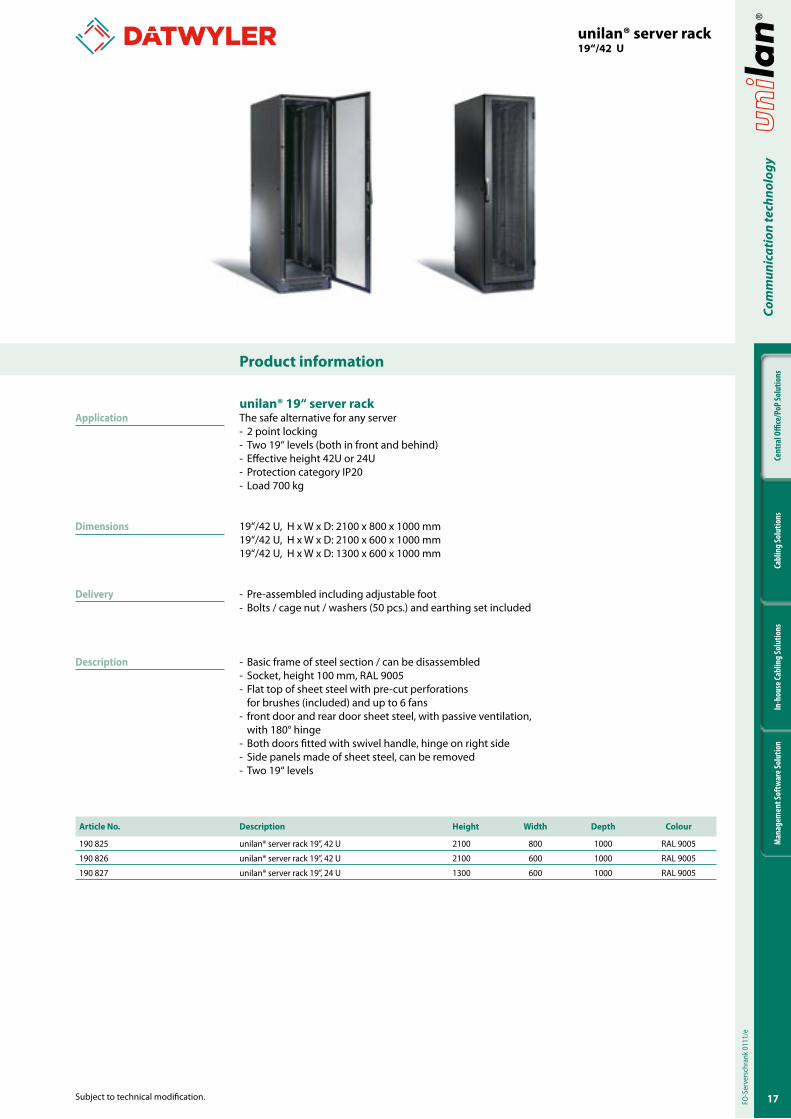
190 825 unilan® server rack 19’’, 42 U 2100 800 1000 RAL 9005
190 826 unilan® server rack 19’’, 42 U 2100 600 1000 RAL 9005
190 827 unilan® server rack 19’’, 24 U 1300 600 1000 RAL 9005
unilan® �9‘‘ server rackThe safe alternative for any server- 2 point locking- Two 19“ levels (both in front and behind)- Effective height 42U or 24U- Protection category IP20- Load 700 kg
19‘‘/42 U, H x W x D: 2100 x 800 x 1000 mm19‘‘/42 U, H x W x D: 2100 x 600 x 1000 mm19‘‘/42 U, H x W x D: 1300 x 600 x 1000 mm
- Pre-assembled including adjustable foot- Bolts / cage nut / washers (50 pcs.) and earthing set included
- Basic frame of steel section / can be disassembled- Socket, height 100 mm, RAL 9005- Flat top of sheet steel with pre-cut perforations for brushes (included) and up to 6 fans- front door and rear door sheet steel, with passive ventilation, with 180° hinge- Both doors fitted with swivel handle, hinge on right side- Side panels made of sheet steel, can be removed- Two 19‘‘ levels
Application
Dimensions
Delivery
Description
FO-S
erve
rsch
rank
011
1/e
�8
Cent
ral O
ffice
/PoP
Solu
tions
Cabl
ing
Solu
tions
In-h
ouse
Cabl
ing
Solu
tions
Man
agem
ent S
oftw
are S
olut
ion
Com
mun
icat
ion
tech
nolo
gy
Product information
Subject to technical modification.
Article No.. Fig. Acessories / Description Comment
401 200 - Operating lever handle on request
401 201 6 Equipment shelf 19‘‘ x 600mm (perforated, fixed, St, 1.5mm), RAL 7035 bearing load 120 kg
401 202 5 Equipment shelf 19‘‘ x 600mm (perforated, pull-out, St, 1.5mm), RAL 7035 bearing load 50 kg
401 203 4 Slide rail set 19‘‘ x 712mm for server rack bearing load 40 kg
401 211 1 Fan set 2 units incl. protective grille and fixing material
401 212 2 Thermostat
401 214 - Power cable 2 m CH
401 221 3 Socket strip CH 10 x Type 13 vertical other variants on request
401 230 8 Mounting kit for wall mounting for wall-mounted housing
401 231 - Mounting kit 19‘‘ bolt / cage nut set of 50
401 232 - Touch-up pen RAL 7035 on request
401 233 - Touch-up pen RAL 9005 on request
401 234 - Adhesive tape for mounting brackets 1-47 U
401 235 - Baying kit for network rack on request
401 237 7 C-profile 600 for SP20 set of 2 on request
401 238 7 C-profile 800 for SP20 set of 2 on request
401 239 7 C-profile 1000 for SP20 set of 2 on request
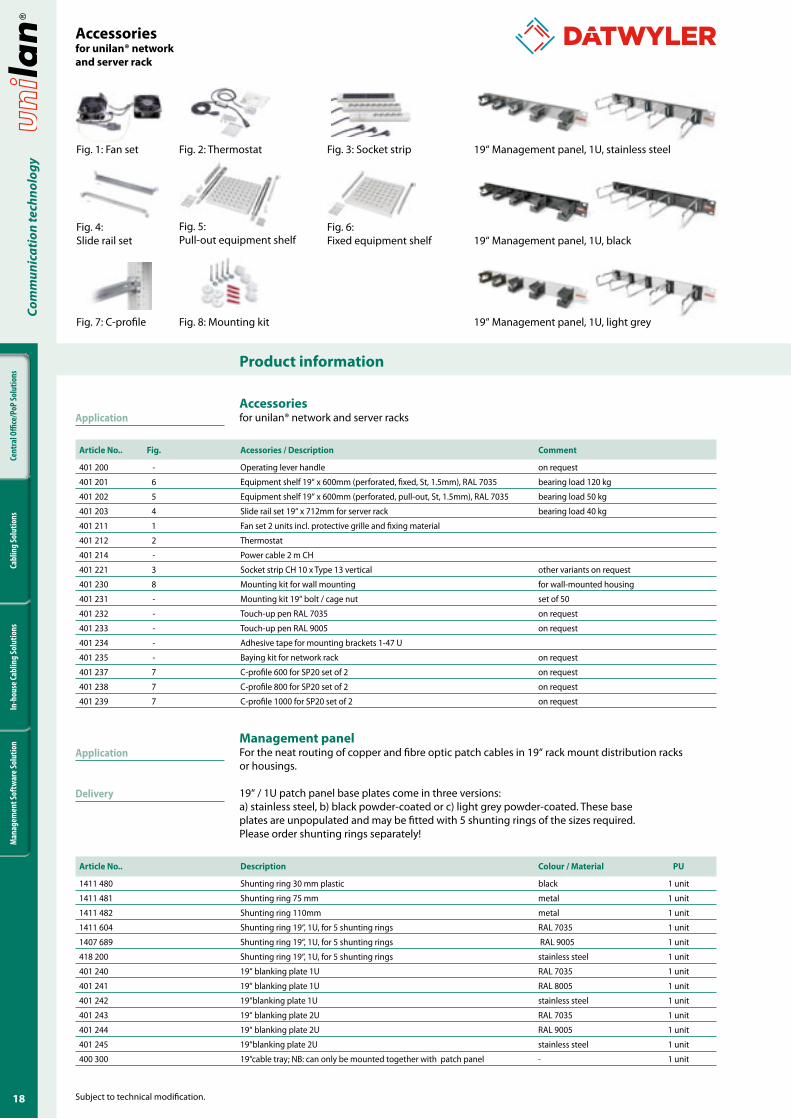
Accessoriesfor unilan® network and server racks
Management panelFor the neat routing of copper and fibre optic patch cables in 19‘‘ rack mount distribution racks or housings.
19‘‘ / 1U patch panel base plates come in three versions:a) stainless steel, b) black powder-coated or c) light grey powder-coated. These base plates are unpopulated and may be fitted with 5 shunting rings of the sizes required. Please order shunting rings separately!
Application
Application
Delivery
Article No.. Description Colour / Material PU
1411 480 Shunting ring 30 mm plastic black 1 unit
1411 481 Shunting ring 75 mm metal 1 unit
1411 482 Shunting ring 110mm metal 1 unit
1411 604 Shunting ring 19‘‘, 1U, for 5 shunting rings RAL 7035 1 unit
1407 689 Shunting ring 19‘‘, 1U, for 5 shunting rings RAL 9005 1 unit
418 200 Shunting ring 19‘‘, 1U, for 5 shunting rings stainless steel 1 unit
401 240 19‘‘ blanking plate 1U RAL 7035 1 unit
401 241 19‘‘ blanking plate 1U RAL 8005 1 unit
401 242 19‘‘blanking plate 1U stainless steel 1 unit
401 243 19‘‘ blanking plate 2U RAL 7035 1 unit
401 244 19‘‘ blanking plate 2U RAL 9005 1 unit
401 245 19‘‘blanking plate 2U stainless steel 1 unit
400 300 19‘‘cable tray; NB: can only be mounted together with patch panel - 1 unit
Accessoriesfor unilan® networkand server rack
Fig. 2: ThermostatFig. 1: Fan set Fig. 3: Socket strip
Fig. 4: Slide rail set
Fig. 6: Fixed equipment shelf
Fig. 7: C-profile Fig. 8: Mounting kit
Fig. 5: Pull-out equipment shelf
19‘‘ Management panel, 1U, light grey
19‘‘ Management panel, 1U, black
19‘‘ Management panel, 1U, stainless steel
�9
Cent
ral O
ffice
/PoP
Solu
tions
Cabl
ing
Solu
tions
In-h
ouse
Cabl
ing
Solu
tions
Man
agem
ent S
oftw
are S
olut
ion
Com
mun
icat
ion
tech
nolo
gy
Product information
Subject to technical modification.
Article No.. Fig. Acessories / Description PU
343 041 - Cable distribution box for fibre optic cable 1 pc
343 042 - Horizontal ALU cable management for patching from front or rear 1 pc
343 043 - Rubber clamps in ALU cable management, length 130mm 1 pc
343 044 - Rubber coating on ALU cable management, 200x100x5mm 1 pc
343 046 - ALU cable management, circular Ø 60mm, length 220 mm 1 pc
343 047 - ALU cable management, semi-circular Ø 60mm, length 220 mm 1 pc
343 048 - Roof without air vents to ODF optical distribution frame 1 pc
343 049 - Roof with air vents to ODF optical distribution frame 1 pc
343 050 - Baseplate with dust filter cartridge 1 pc
343 051 - Doors without air vent, 800mm 1 pc
343 052 - Doors with 40% air vent, 800mm 1 pc
343 053 - Doors with 70% air vent, 800mm 1 pc
343 054 - Double door set, without air vent, 2x600mm 1 pc
343 055 - Double door set, with 40% air vent, 2x600mm 1 pc
343 056 - Double door set, with 70% air vent, 2x600mm 1 pc
343 057 - Side panel 400x2200mm 1 pc
343 058 - Side panel 600x2200mm 1 pc
343 059 - Side panel 800x2200mm 1 pc
343 060 - Side panel 1000x2200mm 1 pc
343 061 - Rear panel 800x2200mm to active component 1 pc
343 062 - Rear panel 1200x2200mm to passive component 1 pc
343 063 - 19‘‘ parking lot, 1U, 24xLCD/APC couplings 1 pc
on request - plinths for racks and rack combinations -
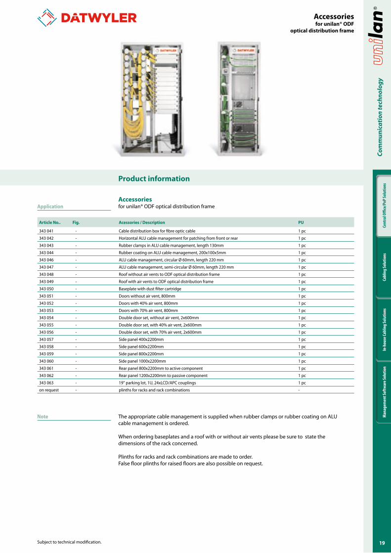
Accessoriesfor unilan® ODF optical distribution frameApplication
Note The appropriate cable management is supplied when rubber clamps or rubber coating on ALU cable management is ordered.
When ordering baseplates and a roof with or without air vents please be sure to state the dimensions of the rack concerned.
Plinths for racks and rack combinations are made to order.False floor plinths for raised floors are also possible on request.
Accessoriesfor unilan® ODF
optical distribution frame
20
Cent
ral O
ffice
/PoP
Solu
tions
Cabl
ing
Solu
tions
In-h
ouse
Cabl
ing
Solu
tions
Man
agem
ent S
oftw
are S
olut
ion
Com
mun
icat
ion
tech
nolo
gy
Product information
Subject to technical modification.
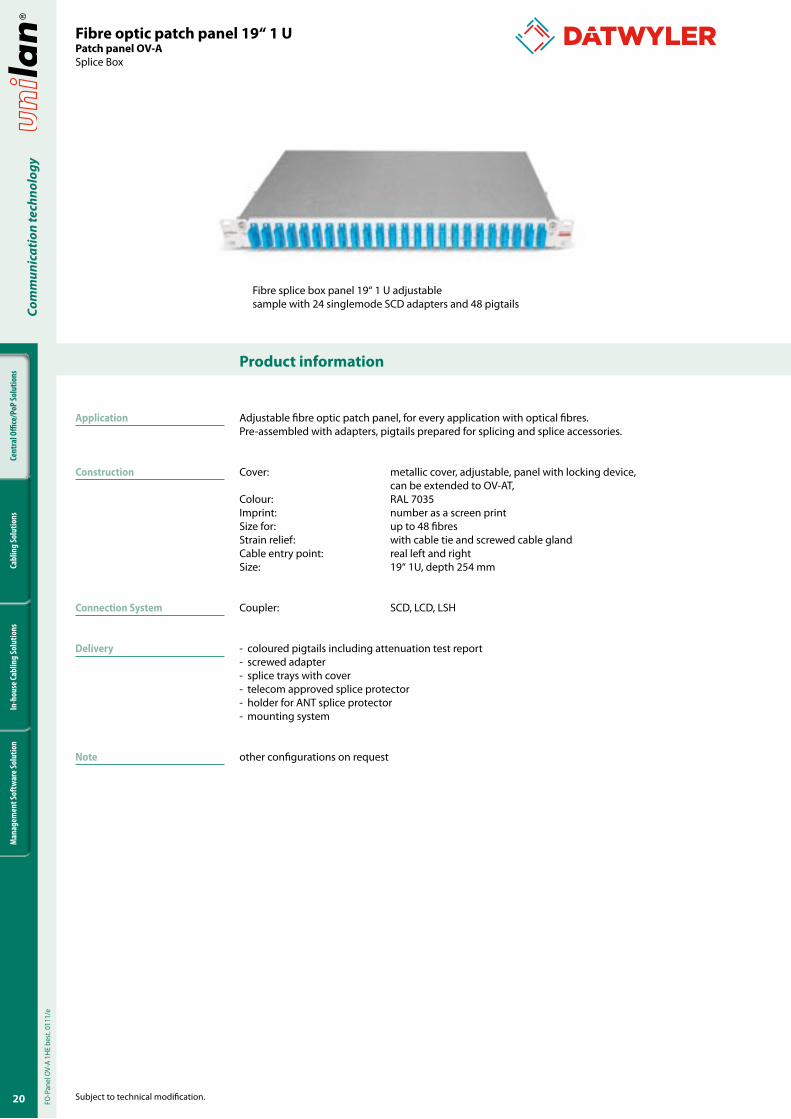
Fibre splice box panel 19‘‘ 1 U adjustablesample with 24 singlemode SCD adapters and 48 pigtails
Adjustable fibre optic patch panel, for every application with optical fibres. Pre-assembled with adapters, pigtails prepared for splicing and splice accessories.
Cover: metallic cover, adjustable, panel with locking device, can be extended to OV-AT, Colour: RAL 7035Imprint: number as a screen printSize for: up to 48 fibresStrain relief: with cable tie and screwed cable glandCable entry point: real left and rightSize: 19“ 1U, depth 254 mm
Coupler: SCD, LCD, LSH
- coloured pigtails including attenuation test report- screwed adapter- splice trays with cover- telecom approved splice protector- holder for ANT splice protector- mounting system
other configurations on request
Fibre optic patch panel �9‘‘ � UPatch panel OV-ASplice Box
Application
Construction
Connection System
Delivery
Note
FO-P
anel
OV-
A 1H
E be
st. 0
111/
e
2�
Cent
ral O
ffice
/PoP
Solu
tions
Cabl
ing
Solu
tions
In-h
ouse
Cabl
ing
Solu
tions
Man
agem
ent S
oftw
are S
olut
ion
Com
mun
icat
ion
tech
nolo
gy
Product information
Subject to technical modification.
Article No. Description
190 968 Splice box OV-A, adjustable, 1 unit 6 LCD adapter blue polymer housing with ceramic sleeve and 12 LC pigtails 2 m E09/125 µm OS2
190 975 Splice box OV-A, adjustable, 1 unit 12 LCD adapter blue polymer housing with ceramic sleeve and 24 LC pigtails 2 m E09/125 µm OS2
190 988 Splice box OV-A, adjustable, 1 unit 12 LCD adapter beiges polymer housing with PB sleeve and 24 LC pigtails 2 m G50/125 µm OM2
191 761 Splice box OV-A, adjustable, 1 unit 24 LCD adapter blue polymer housing with ceramic sleeve and 48 LC pigtails 2 m E09/125 µm OS2
190 989 Splice box OV-A, adjustable, 1 unit 6 LSH/APC adapter green polymer housing with ceramic sleeve and 6 LSH/APC pigtails 2 m E09/125 µm OS2
190 893 Splice box OV-A, adjustable, 1 unit 12 LSH/APC adapter green polymer housing with ceramic sleeve and 12 LSH/APC pigtails 2 m E09/125 µm OS2
190 894 Splice box OV-A, adjustable, 1 unit 24 LSH/APC adapter green polymer housing with ceramic sleeve and 24 LSH/APC pigtails 2 m E09/125 µm OS2
190 888 Splice box OV-A, adjustable, 1 unit 6 SCD adapter blue polymer housing with ceramic sleeve and 12 SC pigtails 2 m E09/125 µm OS2
190 889 Splice box OV-A, adjustable, 1 unit 12 SCD adapter blue polymer housing with ceramic sleeve and 24 SC pigtails 2 m E09/125 µm OS2
190 973 Splice box OV-A, adjustable, 1 unit 24 SCD adapter blue polymer housing with ceramic sleeve and 48 SC pigtails 2 m E09/125 µm OS2
309 427 Splice box OV-A, adjustable, 1 unit 2 LCD- adapter green polymer housing with ceramic sleeve and 4 LC/APC pigtails 2m E09/125 µm OS2
309 454 Splice box OV-A, adjustable, 1 unit 6 LCD- adapter green polymer housing with ceramic sleeve and 12 LC/APC pigtails 2m E09/125 µm OS2
309 455 Splice box OV-A, adjustable, 1 unit 12 LCD- adapter green polymer housing with ceramic sleeve and 24 LC/APC pigtails 2m E09/125 µm OS2
309 418 Splice box OV-A, adjustable, 1 unit 24 LCD- adapter, green polymer housing with ceramic sleeve and 48 LC/APC Pigtails 2m E09/125 µm OS2
Fibre optic patch panel �9‘‘ � UPatch panel OV-ASplice Box
22
Cent
ral O
ffice
/PoP
Solu
tions
Cabl
ing
Solu
tions
In-h
ouse
Cabl
ing
Solu
tions
Man
agem
ent S
oftw
are S
olut
ion
Com
mun
icat
ion
tech
nolo
gy
Product information
Subject to technical modification.
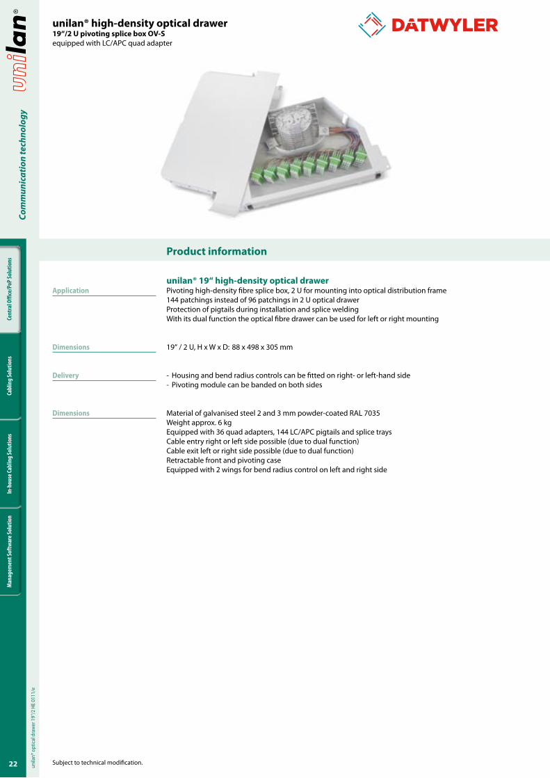
unilan® high-density optical drawer�9‘‘/2 U pivoting splice box OV-Sequipped with LC/APC quad adapter
unilan® �9‘‘ high-density optical drawerPivoting high-density fibre splice box, 2 U for mounting into optical distribution frame144 patchings instead of 96 patchings in 2 U optical drawerProtection of pigtails during installation and splice weldingWith its dual function the optical fibre drawer can be used for left or right mounting
19‘‘ / 2 U, H x W x D: 88 x 498 x 305 mm
- Housing and bend radius controls can be fitted on right- or left-hand side- Pivoting module can be banded on both sides
Material of galvanised steel 2 and 3 mm powder-coated RAL 7035Weight approx. 6 kgEquipped with 36 quad adapters, 144 LC/APC pigtails and splice traysCable entry right or left side possible (due to dual function)Cable exit left or right side possible (due to dual function)Retractable front and pivoting caseEquipped with 2 wings for bend radius control on left and right side
Application
Dimensions
Delivery
Dimensions
unila
n® o
ptic
al d
raw
er 1
9‘‘/2
HE
0111
/e
23
Cent
ral O
ffice
/PoP
Solu
tions
Cabl
ing
Solu
tions
In-h
ouse
Cabl
ing
Solu
tions
Man
agem
ent S
oftw
are S
olut
ion
Com
mun
icat
ion
tech
nolo
gy
Product information
Subject to technical modification.
unilan® high-density optical drawer�9‘‘/2 U pivoting splice box OV-Sequipped with LC/APC quad adapter
Article No. Description Opening Equipment Pigtail Colour
343 101 unilan® optical drawer 19‘‘, pivoting, 2 U right LC/APC quad adapter Fibre G.652.D colour code white RAL 7035
343 102 unilan® optical drawer 19‘‘, pivoting, 2 U right LC/APC quad adapter Fibre G.652.D colour code yellow RAL 7035
343 103 unilan® optical drawer 19‘‘, pivoting, 2 U right LC/APC quad adapter Fibre G.652.D colour code Swisscom RAL 7035
343 104 unilan® optical drawer 19‘‘, pivoting, 2 U right LC/APC quad adapter Fibre G.652.D colour code D.Telecom RAL 7035
343 105 unilan® optical drawer 19‘‘, pivoting, 2 U right LC/APC quad adapter Fibre G.652.D colour code Telcordia RAL 7035
343 121 unilan® optical drawer 19‘‘, pivoting, 2 U left LC/APC quad adapter Fibre G.652.D colour code white RAL 7035
343 122 unilan® optical drawer 19‘‘, pivoting, 2 U left LC/APC quad adapter Fibre G.652.D colour code yellow RAL 7035
343 123 unilan® optical drawer 19‘‘, pivoting, 2 U left LC/APC quad adapter Fibre G.652.D colour code Swisscom RAL 7035
343 124 unilan® optical drawer 19‘‘, pivoting, 2 U left LC/APC quad adapter Fibre G.652.D colour code D.Telecom RAL 7035
343 125 unilan® optical drawer 19‘‘, pivoting, 2 U left LC/APC quad adapter Fibre G.652.D colour code Telcordia RAL 7035
Other configurations on request.
24
Cent
ral O
ffice
/PoP
Solu
tions
Cabl
ing
Solu
tions
In-h
ouse
Cabl
ing
Solu
tions
Man
agem
ent S
oftw
are S
olut
ion
Com
mun
icat
ion
tech
nolo
gy
Product information
Subject to technical modification.
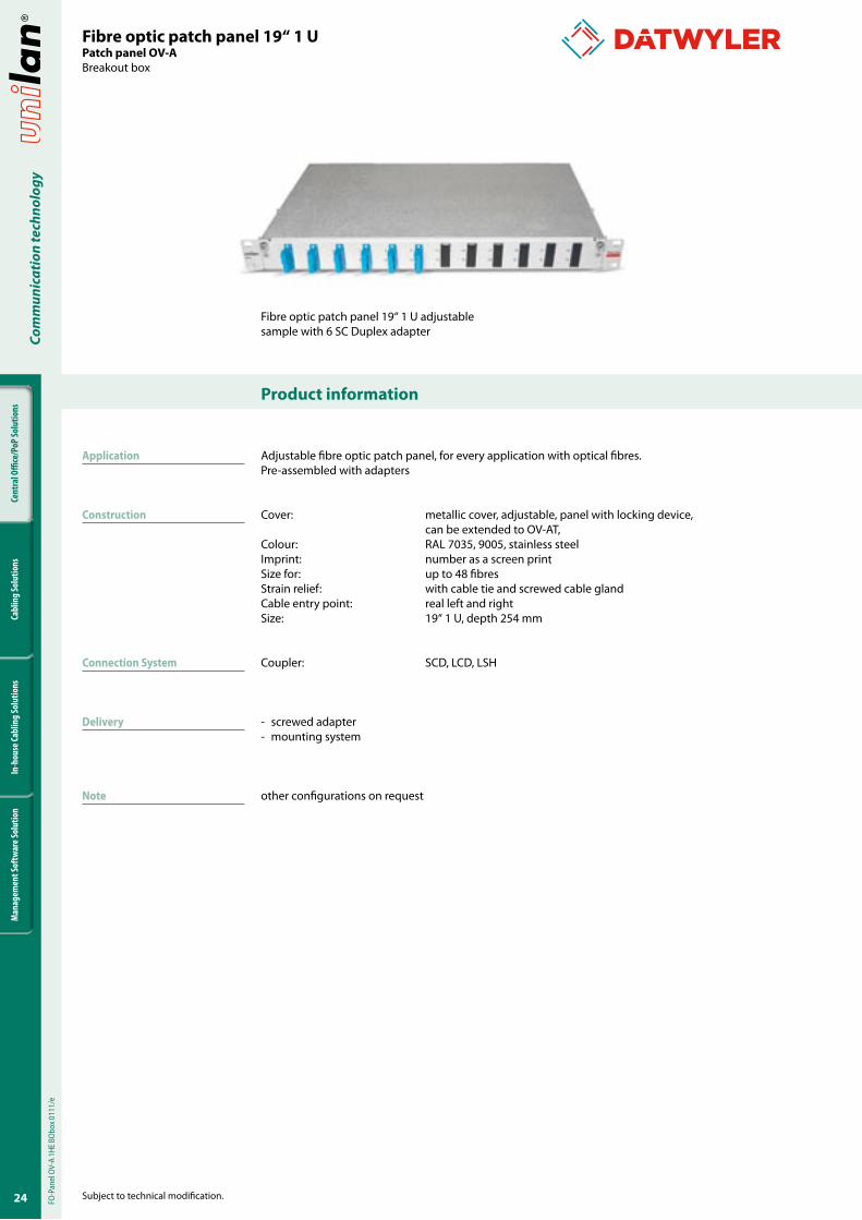
Fibre optic patch panel 19‘‘ 1 U adjustablesample with 6 SC Duplex adapter
Adjustable fibre optic patch panel, for every application with optical fibres. Pre-assembled with adapters
Cover: metallic cover, adjustable, panel with locking device, can be extended to OV-AT, Colour: RAL 7035, 9005, stainless steelImprint: number as a screen printSize for: up to 48 fibresStrain relief: with cable tie and screwed cable glandCable entry point: real left and rightSize: 19“ 1 U, depth 254 mm
Coupler: SCD, LCD, LSH
- screwed adapter- mounting system
other configurations on request
Fibre optic patch panel �9‘‘ � UPatch panel OV-ABreakout box
Application
Construction
Connection System
Delivery
Note
FO-P
anel
OV-
A 1H
E BO
box 0
111/
e
2�
Cent
ral O
ffice
/PoP
Solu
tions
Cabl
ing
Solu
tions
In-h
ouse
Cabl
ing
Solu
tions
Man
agem
ent S
oftw
are S
olut
ion
Com
mun
icat
ion
tech
nolo
gy
Product information
Subject to technical modification.
Article No. Description
191 765 Breakout box OV-A, adjustable, 1 U 6 LCD SM adapter, blue polymer housing with ceramic sleeve
191 767 Breakout box OV-A, adjustable, 1 U 12 LCD SM adapter, blue polymer housing with ceramic sleeve
191 769 Breakout box OV-A, adjustable, 1 U 24 LCD SM adapter, blue polymer housing with ceramic sleeve
191 771 Breakout box OV-A, adjustable, 1 U 6 LSH/APC SM adapter, green polymer housing with ceramic sleeve
190 878 Breakout box OV-A, adjustable, 1 U 12 LSH/APC SM adapter, green polymer housing with ceramic sleeve
190 879 Breakout box OV-A, adjustable, 1 U 24 LSH/APC SM adapter, green polymer housing with ceramic sleeve
190 876 Breakout box OV-A, adjustable, 1 U 6 SCD SM adapter, blue polymer housing with ceramic sleeve
190 877 Breakout box OV-A, adjustable, 1 U 12 SCD SM adapter, blue polymer housing with ceramic sleeve
191 775 Breakout box OV-A, adjustable, 1 U 24 SCD SM adapter, blue polymer housing with ceramic sleeve
309 456 Breakout box OV-A, adjustable, 1 U 6 LCD/APC SM adapter, green polymer housing with ceramic sleeve
309 457 Breakout box OV-A, adjustable, 1 U 12 LCD/APC SM adapter, green polymer housing with ceramic sleeve
309 458 Breakout box OV-A, adjustable, 1 U 24 LCD/APC SM adapter, green polymer housing with ceramic sleeve
Fibre optic patch panel �9‘‘ � UPatch panel OV-ABreakout box
26
Cent
ral O
ffice
/PoP
Solu
tions
Cabl
ing
Solu
tions
In-h
ouse
Cabl
ing
Solu
tions
Man
agem
ent S
oftw
are S
olut
ion
Com
mun
icat
ion
tech
nolo
gy
Product information
Subject to technical modification.
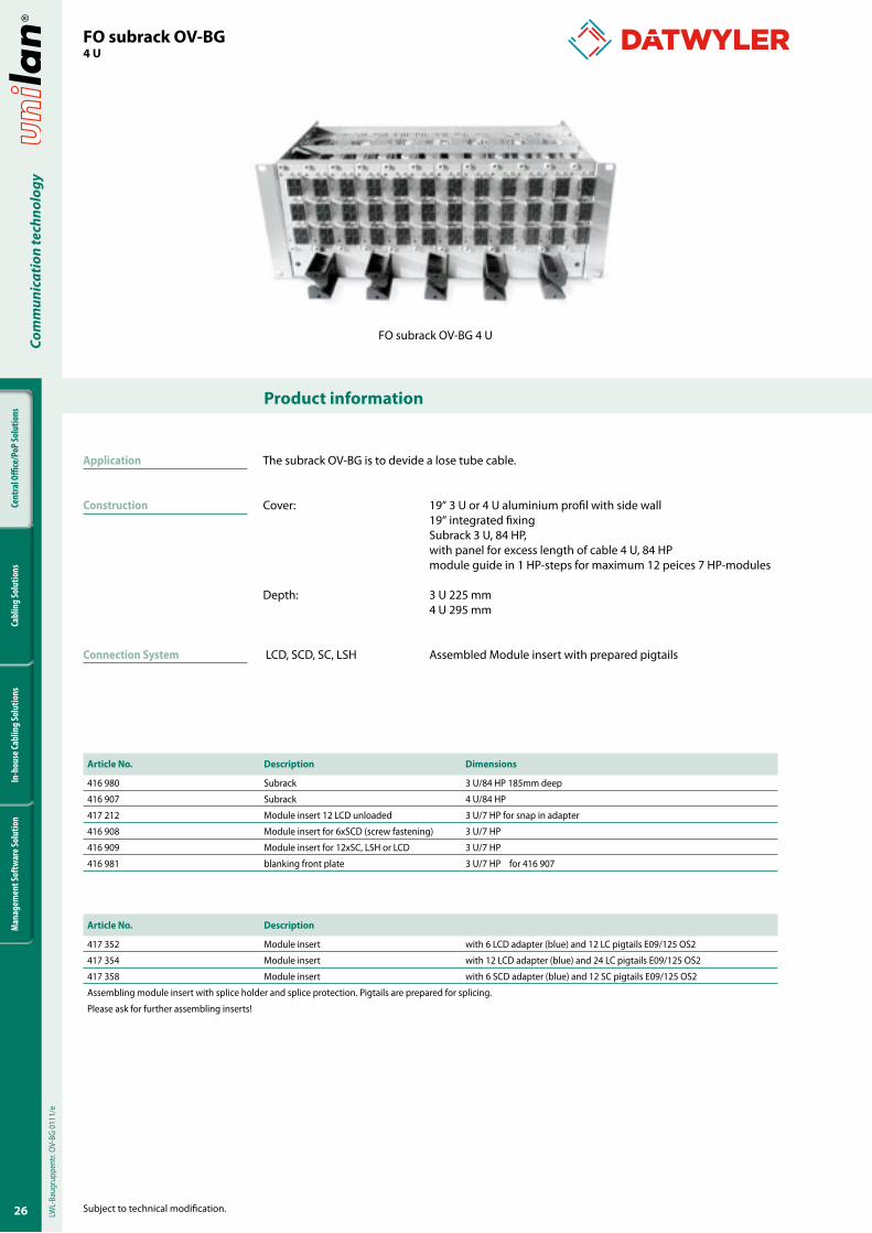
FO subrack OV-BG 4 U
The subrack OV-BG is to devide a lose tube cable.
Cover: 19“ 3 U or 4 U aluminium profil with side wall 19“ integrated fixing Subrack 3 U, 84 HP, with panel for excess length of cable 4 U, 84 HP module guide in 1 HP-steps for maximum 12 peices 7 HP-modules Depth: 3 U 225 mm 4 U 295 mm
LCD, SCD, SC, LSH Assembled Module insert with prepared pigtails
FO subrack OV-BG4 U
Article No. Description Dimensions
416 980 Subrack 3 U/84 HP 185mm deep
416 907 Subrack 4 U/84 HP
417 212 Module insert 12 LCD unloaded 3 U/7 HP for snap in adapter
416 908 Module insert for 6xSCD (screw fastening) 3 U/7 HP
416 909 Module insert for 12xSC, LSH or LCD 3 U/7 HP
416 981 blanking front plate 3 U/7 HP for 416 907
Article No. Description
417 352 Module insert with 6 LCD adapter (blue) and 12 LC pigtails E09/125 OS2
417 354 Module insert with 12 LCD adapter (blue) and 24 LC pigtails E09/125 OS2
417 358 Module insert with 6 SCD adapter (blue) and 12 SC pigtails E09/125 OS2
Assembling module insert with splice holder and splice protection. Pigtails are prepared for splicing.
Please ask for further assembling inserts!
Application
Construction
Connection System
LWL-
Baug
rupp
entr.
OV-
BG 0
111/
e
2�
Cent
ral O
ffice
/PoP
Solu
tions
Cabl
ing
Solu
tions
In-h
ouse
Cabl
ing
Solu
tions
Man
agem
ent S
oftw
are S
olut
ion
Com
mun
icat
ion
tech
nolo
gy
Product information
Subject to technical modification.
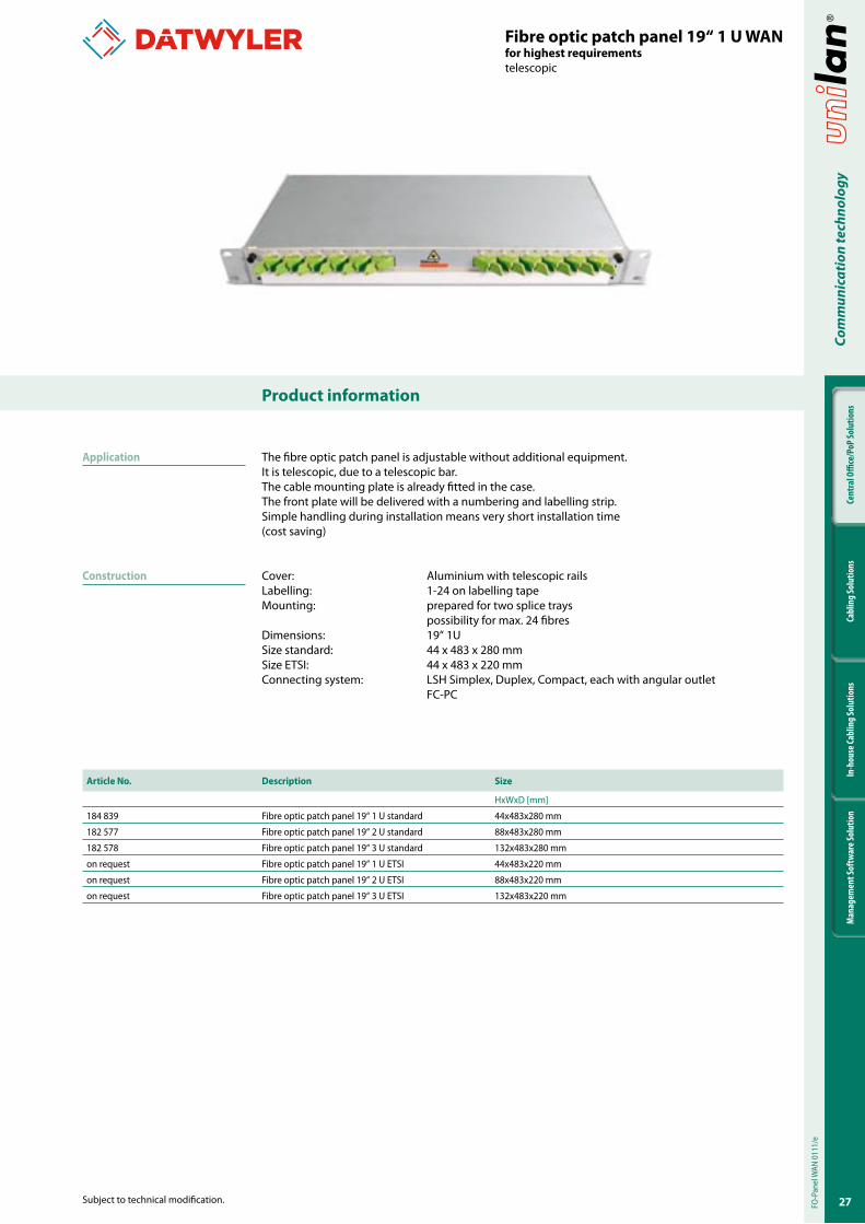
The fibre optic patch panel is adjustable without additional equipment.It is telescopic, due to a telescopic bar.The cable mounting plate is already fitted in the case.The front plate will be delivered with a numbering and labelling strip.Simple handling during installation means very short installation time (cost saving)
Cover: Aluminium with telescopic railsLabelling: 1-24 on labelling tapeMounting: prepared for two splice trays possibility for max. 24 fibresDimensions: 19“ 1USize standard: 44 x 483 x 280 mmSize ETSI: 44 x 483 x 220 mmConnecting system: LSH Simplex, Duplex, Compact, each with angular outlet FC-PC
Fibre optic patch panel �9“ � U WANfor highest requirementstelescopic
Article No. Description Size
HxWxD [mm]
184 839 Fibre optic patch panel 19“ 1 U standard 44x483x280 mm
182 577 Fibre optic patch panel 19“ 2 U standard 88x483x280 mm
182 578 Fibre optic patch panel 19“ 3 U standard 132x483x280 mm
on request Fibre optic patch panel 19“ 1 U ETSI 44x483x220 mm
on request Fibre optic patch panel 19“ 2 U ETSI 88x483x220 mm
on request Fibre optic patch panel 19“ 3 U ETSI 132x483x220 mm
Application
Construction
FO-P
anel
WAN
011
1/e
28
Cent
ral O
ffice
/PoP
Solu
tions
Cabl
ing
Solu
tions
In-h
ouse
Cabl
ing
Solu
tions
Man
agem
ent S
oftw
are S
olut
ion
Com
mun
icat
ion
tech
nolo
gy
Product information
Subject to technical modification.
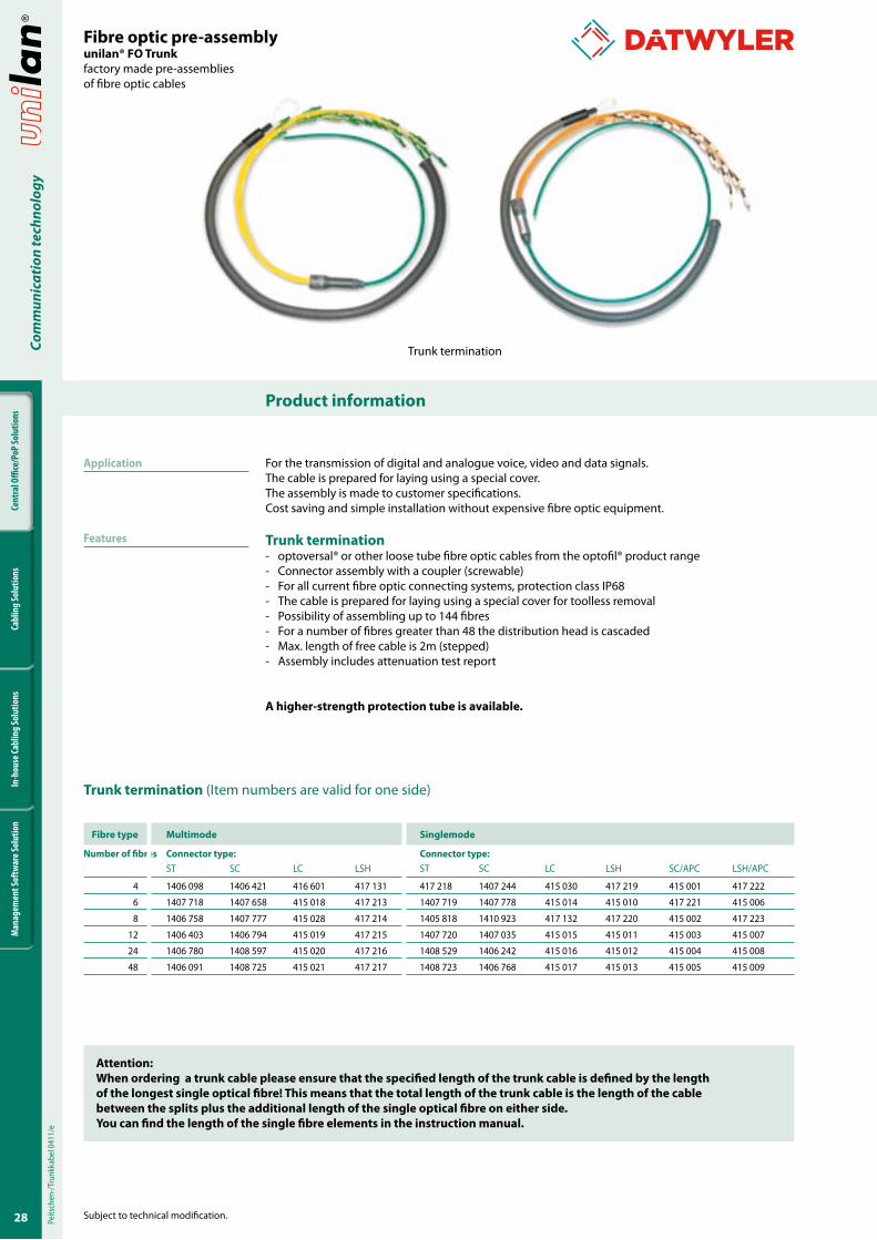
For the transmission of digital and analogue voice, video and data signals.The cable is prepared for laying using a special cover.The assembly is made to customer specifications.Cost saving and simple installation without expensive fibre optic equipment.
Trunk termination- optoversal® or other loose tube fibre optic cables from the optofil® product range- Connector assembly with a coupler (screwable)- For all current fibre optic connecting systems, protection class IP68- The cable is prepared for laying using a special cover for toolless removal- Possibility of assembling up to 144 fibres- For a number of fibres greater than 48 the distribution head is cascaded- Max. length of free cable is 2m (stepped)- Assembly includes attenuation test report
A higher-strength protection tube is available.
Fibre optic pre-assemblyunilan® FO Trunkfactory made pre-assemblies of fibre optic cables
Trunk termination
Peits
chen
-/Tru
nkka
bel 0
411/
e
Application
Features
Attention:When ordering a trunk cable please ensure that the specified length of the trunk cable is defined by the length of the longest single optical fibre! This means that the total length of the trunk cable is the length of the cable between the splits plus the additional length of the single optical fibre on either side. You can find the length of the single fibre elements in the instruction manual.
Trunk termination (Item numbers are valid for one side)
Fibre type Multimode Singlemode
Number of fibres Connector type: Connector type: ST SC LC LSH ST SC LC LSH SC/APC LSH/APC
4 1406 098 1406 421 416 601 417 131 417 218 1407 244 415 030 417 219 415 001 417 222
6 1407 718 1407 658 415 018 417 213 1407 719 1407 778 415 014 415 010 417 221 415 006
8 1406 758 1407 777 415 028 417 214 1405 818 1410 923 417 132 417 220 415 002 417 223
12 1406 403 1406 794 415 019 417 215 1407 720 1407 035 415 015 415 011 415 003 415 007
24 1406 780 1408 597 415 020 417 216 1408 529 1406 242 415 016 415 012 415 004 415 008
48 1406 091 1408 725 415 021 417 217 1408 723 1406 768 415 017 415 013 415 005 415 009

29
Cent
ral O
ffice
/PoP
Solu
tions
Cabl
ing
Solu
tions
In-h
ouse
Cabl
ing
Solu
tions
Man
agem
ent S
oftw
are S
olut
ion
Com
mun
icat
ion
tech
nolo
gy
Product information
Subject to technical modification.
Fibre optic pre-assemblyunilan® FO Trunkfactory made pre-assemblies of fibre optic cablesConnector assembly / Breakout assembly
For the transmission of digital and analogue voice, video and data signals.The assembly is made to customer specifications.Cost saving and simple installation without expensive fibre optic equipment.
Breakout assembly- Breakout single fibre cable assembly- Assemblies for all current fibre optic connecting systems- The cable is prepared for laying using a special cover- Single semi loose tube, stepped- Assembly includes attenuation test report
Breakout assembly
Brea
kout
Kon
fekt
ion
0411
/e
Application
Features
Attention:When ordering a trunk cable please ensure that the specified length of the trunk cable is defined by the length of the longest single optical fibre! This means that the total length of the trunk cable is the length of the cable between the splits plus the additional length of the single optical fibre on either side. You can find the length of the single fibre elements in the instruction manual.
Breakout assembly (Item numbers are valid for one side)
Breakout assembly Connector type Number of connectors Type of multimode Type of single mode
on each cable end Article No. Article No.
SC 4 1410 596 415 023
SC 8 1410 597 415 024
SC 12 1410 598 415 025
SC 24 415 083 415 081
SC 48 415 084 415082
LC 4 415 085 415 090
LC 8 415 086 415 091
LC 12 415 087 415 092
LC 24 415 088 415 093
LC 48 415 089 415 094

30
Cent
ral O
ffice
/PoP
Solu
tions
Cabl
ing
Solu
tions
In-h
ouse
Cabl
ing
Solu
tions
Man
agem
ent S
oftw
are S
olut
ion
Com
mun
icat
ion
tech
nolo
gy
Product information
Subject to technical modification.
Fibre optic pigtails
Type of connector Type of Fibre Fibre pigtail 2 m Set of �2 pcs. FP 2 m*
SC E09/OS2 421 121 421 122
LC E09/OS2 423 321 423 322
LC/APC E09/OS2 429 921 429 922
LSH E09/OS2 424 421 424 422
FC/PC E09/OS2 425 521 425 522
SC/APC E09/OS2 427 721 427 722
LSH/APC E09/OS2 428 821 428 822
* Set has 12 fibre pigtails in 12 colours (according IEC 60304).
Other pigtails on request.
FO-P
igta
ils 0
111/
e
3�
Cent
ral O
ffice
/PoP
Solu
tions
Cabl
ing
Solu
tions
In-h
ouse
Cabl
ing
Solu
tions
Man
agem
ent S
oftw
are S
olut
ion
Com
mun
icat
ion
tech
nolo
gy
Product information
Subject to technical modification.
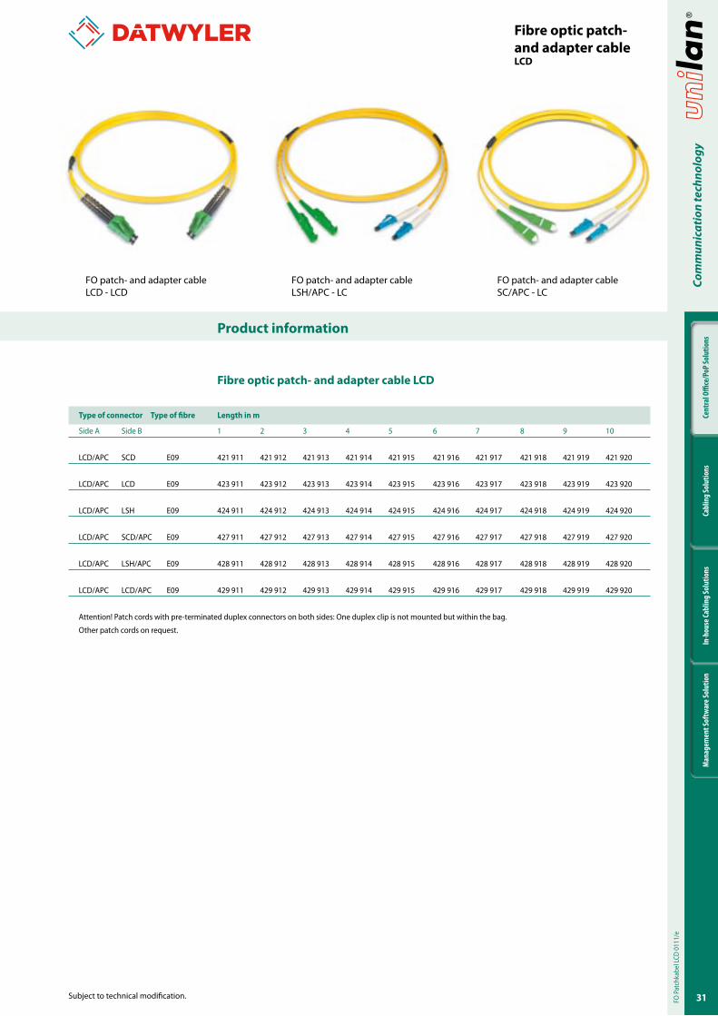
Fibre optic patch- and adapter cableLCD
Type of connector Type of fibre Length in m
Side A Side B 1 2 3 4 5 6 7 8 9 10
LCD/APC SCD E09 421 911 421 912 421 913 421 914 421 915 421 916 421 917 421 918 421 919 421 920
LCD/APC LCD E09 423 911 423 912 423 913 423 914 423 915 423 916 423 917 423 918 423 919 423 920
LCD/APC LSH E09 424 911 424 912 424 913 424 914 424 915 424 916 424 917 424 918 424 919 424 920
LCD/APC SCD/APC E09 427 911 427 912 427 913 427 914 427 915 427 916 427 917 427 918 427 919 427 920
LCD/APC LSH/APC E09 428 911 428 912 428 913 428 914 428 915 428 916 428 917 428 918 428 919 428 920
LCD/APC LCD/APC E09 429 911 429 912 429 913 429 914 429 915 429 916 429 917 429 918 429 919 429 920
Attention! Patch cords with pre-terminated duplex connectors on both sides: One duplex clip is not mounted but within the bag.
Other patch cords on request.
Fibre optic patch- and adapter cable LCD
FO patch- and adapter cableLCD - LCD
FO patch- and adapter cableLSH/APC - LC
FO patch- and adapter cableSC/APC - LC
FO P
atch
kabe
l LCD
011
1/e
32
Cent
ral O
ffice
/PoP
Solu
tions
Cabl
ing
Solu
tions
In-h
ouse
Cabl
ing
Solu
tions
Man
agem
ent S
oftw
are S
olut
ion
Com
mun
icat
ion
tech
nolo
gy
Product information
Subject to technical modification.
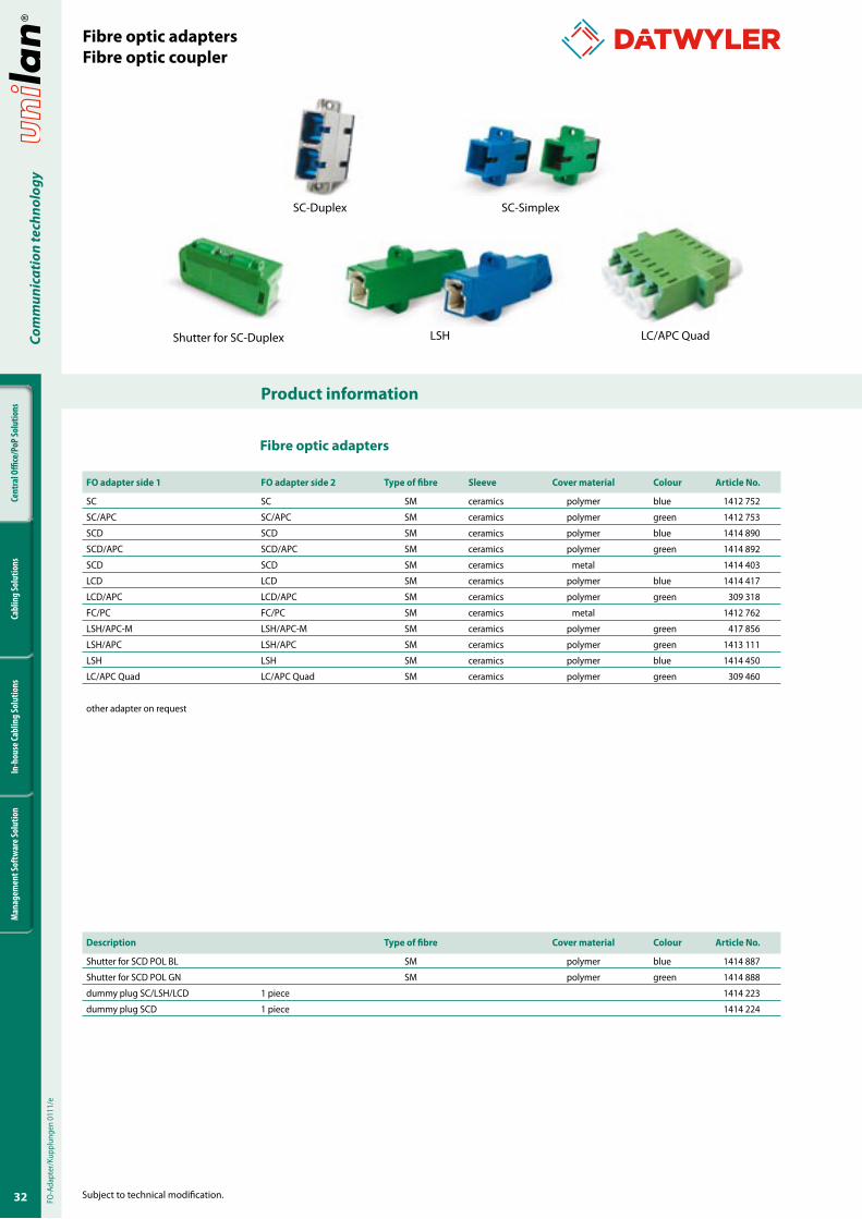
Fibre optic adaptersFibre optic coupler
Fibre optic adapters
FO adapter side � FO adapter side 2 Type of fibre Sleeve Cover material Colour Article No.
SC SC SM ceramics polymer blue 1412 752
SC/APC SC/APC SM ceramics polymer green 1412 753
SCD SCD SM ceramics polymer blue 1414 890
SCD/APC SCD/APC SM ceramics polymer green 1414 892
SCD SCD SM ceramics metal 1414 403
LCD LCD SM ceramics polymer blue 1414 417
LCD/APC LCD/APC SM ceramics polymer green 309 318
FC/PC FC/PC SM ceramics metal 1412 762
LSH/APC-M LSH/APC-M SM ceramics polymer green 417 856
LSH/APC LSH/APC SM ceramics polymer green 1413 111
LSH LSH SM ceramics polymer blue 1414 450
LC/APC Quad LC/APC Quad SM ceramics polymer green 309 460
other adapter on request
FO-A
dapt
er/K
uppl
unge
n 01
11/e
Description Type of fibre Cover material Colour Article No.
Shutter for SCD POL BL SM polymer blue 1414 887
Shutter for SCD POL GN SM polymer green 1414 888
dummy plug SC/LSH/LCD 1 piece 1414 223
dummy plug SCD 1 piece 1414 224
SC-Duplex SC-Simplex
Shutter for SC-Duplex LSH LC/APC Quad
33
Cent
ral O
ffice
/PoP
Solu
tions
Cabl
ing
Solu
tions
In-h
ouse
Cabl
ing
Solu
tions
Man
agem
ent S
oftw
are S
olut
ion
Com
mun
icat
ion
tech
nolo
gy
Product information
Subject to technical modification.
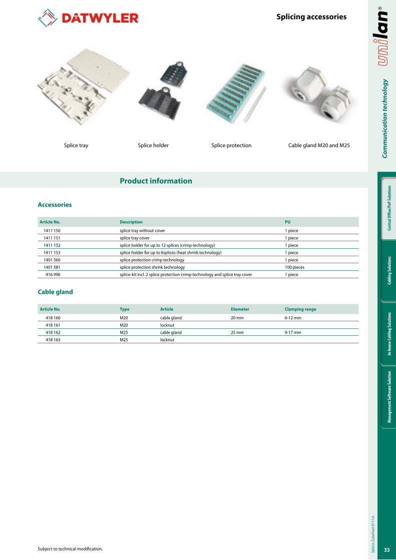
Splicing accessories
Accessories
Article No. Description PU
1411 150 splice tray without cover 1 piece
1411 151 splice tray cover 1 piece
1411 152 splice holder for up to 12 splices (crimp technology) 1 piece
1411 153 splice holder for up to 6splices (heat shrink technology) 1 piece
1401 560 splice protection crimp technology 1 piece
1401 581 splice protection shrink technology 100 pieces
416 996 splice-kit incl. 2 splice protection crimp technology and splice tray cover 1 piece
Cable gland
Article No. Type Article Diameter Clamping range
418 160 M20 cable gland 20 mm 6-12 mm
418 161 M20 locknut
418 162 M25 cable gland 25 mm 9-17 mm
418 163 M25 locknut
Sple
iss-Z
ubeh
oer 0
111/
e
Splice tray Splice holder Splice protection Cable gland M20 and M25
34
Cent
ral O
ffice
/PoP
Solu
tions
Cabl
ing
Solu
tions
In-h
ouse
Cabl
ing
Solu
tions
Man
agem
ent S
oftw
are S
olut
ion
Subject to technical modification.
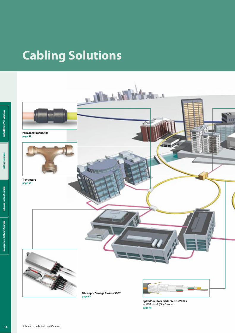
Cabling Solutions
Fibre optic Sewage Closure SCO2page 63
Permanent connectorpage �2
T enclosurepage �6
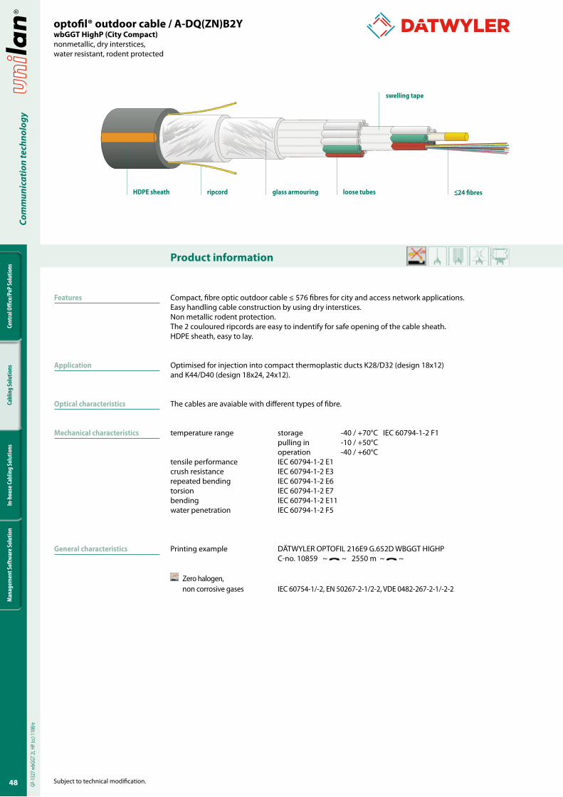
optofil® outdoor cable / A-DQ(ZN)B2YwbGGT HighP (City Compact)page 48
3�
Cent
ral O
ffice
/PoP
Solu
tions
Cabl
ing
Solu
tions
In-h
ouse
Cabl
ing
Solu
tions
Man
agem
ent S
oftw
are S
olut
ion
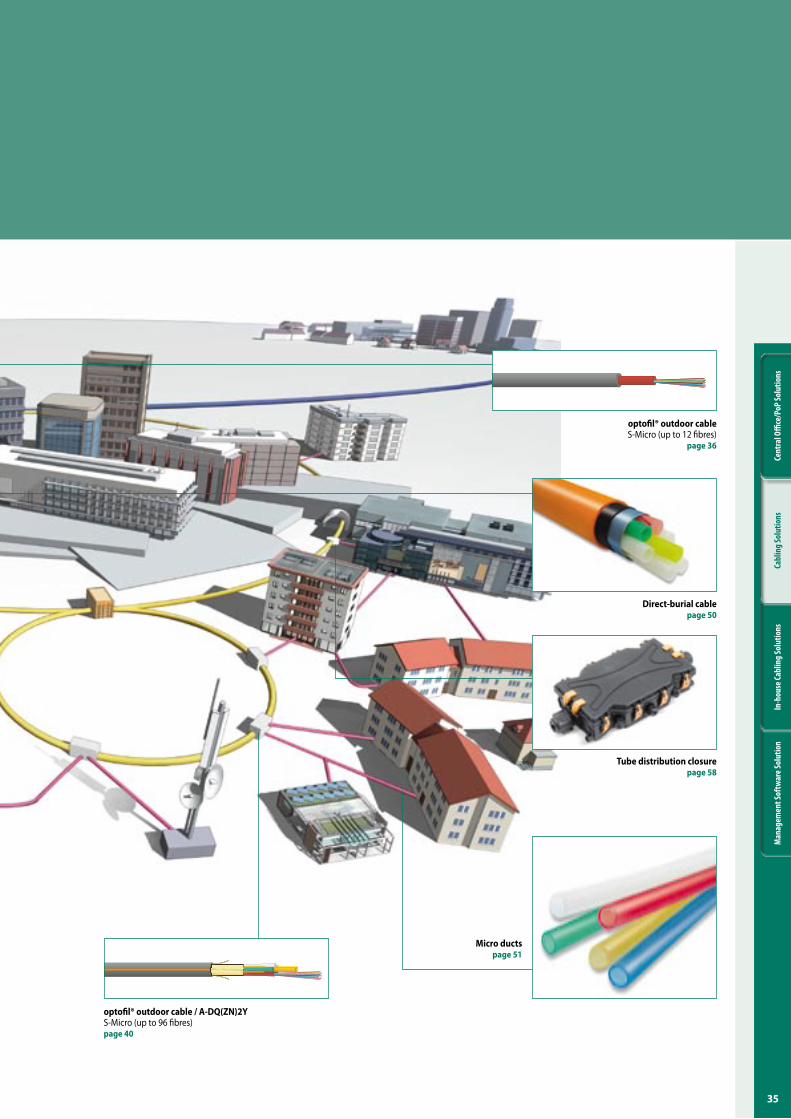
Micro ductspage ��
optofil® outdoor cable / A-DQ(ZN)2YS-Micro (up to 96 fibres)page 40
Direct-burial cablepage �0
Tube distribution closurepage �8
optofil® outdoor cable S-Micro (up to 12 fibres)
page 36
36
Cent
ral O
ffice
/PoP
Solu
tions
Cabl
ing
Solu
tions
In-h
ouse
Cabl
ing
Solu
tions
Man
agem
ent S
oftw
are S
olut
ion
Com
mun
icat
ion
tech
nolo
gy
Product information
Subject to technical modification.
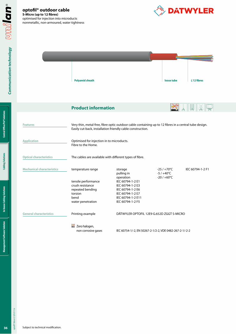
optofil® outdoor cable S-Micro (up to �2 fibres)optimised for injection into microductsnonmetallic, non-armoured, water tightness
Features
Application
Optical characteristics
Mechanical characteristics
General characteristics
Very thin, metal-free, fibre optic outdoor cable containing up to 12 fibres in a central tube design.Easily cut-back, installation friendly cable construction.
Optimised for injection in to microducts.Fibre to the Home.
The cables are available with different types of fibre.
temperature range storage -25 / +70°C IEC 60794-1-2 F1 pulling in -5 / +40°C operation -20 / +60°Ctensile performance IEC 60794-1-2 E1crush resistance IEC 60794-1-2 E3repeated bending IEC 60794-1-2 E6torsion IEC 60794-1-2 E7bend IEC 60794-1-2 E11water penetration IEC 60794-1-2 F5
Printing example DÄTWYLER OPTOFIL 12E9 G.652D ZGGT S-MICRO
Zero halogen, non corrosive gases IEC 60754-1/-2, EN 50267-2-1/2-2, VDE 0482-267-2-1/-2-2
opto
fil® M
icro-
S 12F
0111
/e
loose tubePolyamid sheath < �2 fibres
3�
Cent
ral O
ffice
/PoP
Solu
tions
Cabl
ing
Solu
tions
In-h
ouse
Cabl
ing
Solu
tions
Man
agem
ent S
oftw
are S
olut
ion
Com
mun
icat
ion
tech
nolo
gy
Subject to technical modification.
Varianten
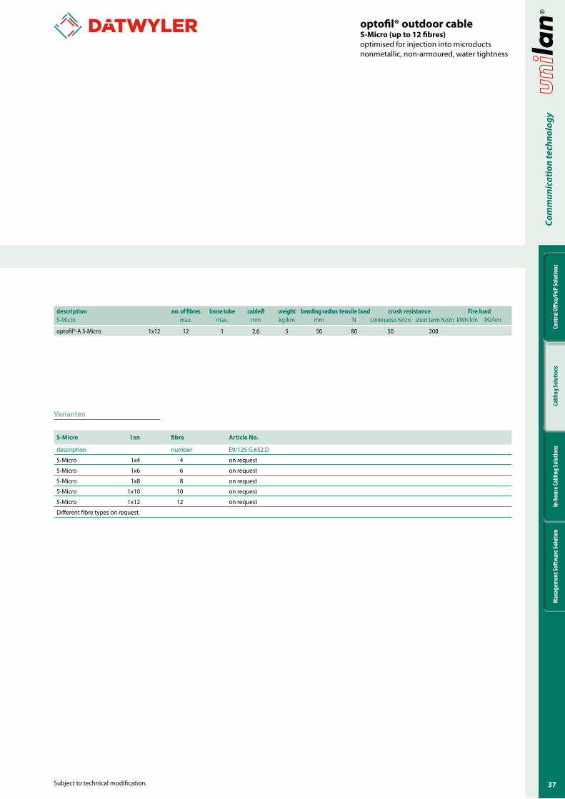
S-Micro �xn fibre Article No.
description number E9/125 G.652.D
S-Micro 1x4 4 on request
S-Micro 1x6 6 on request
S-Micro 1x8 8 on request
S-Micro 1x10 10 on request
S-Micro 1x12 12 on request
Different fibre types on request.
description no. of fibres loose tube cableØ weight bending radius tensile load crush resistance Fire loadS-Micro max. max. mm kg/km mm N continuous N/cm short term N/cm kWh/km MJ/km
optofil®-A S-Micro 1x12 12 1 2,6 5 50 80 50 200
optofil® outdoor cable S-Micro (up to �2 fibres)optimised for injection into microductsnonmetallic, non-armoured, water tightness
38
Cent
ral O
ffice
/PoP
Solu
tions
Cabl
ing
Solu
tions
In-h
ouse
Cabl
ing
Solu
tions
Man
agem
ent S
oftw
are S
olut
ion
Com
mun
icat
ion
tech
nolo
gy
Product information
Subject to technical modification.
Features
Application
Optical characteristics
Mechanical characteristics
General characteristics
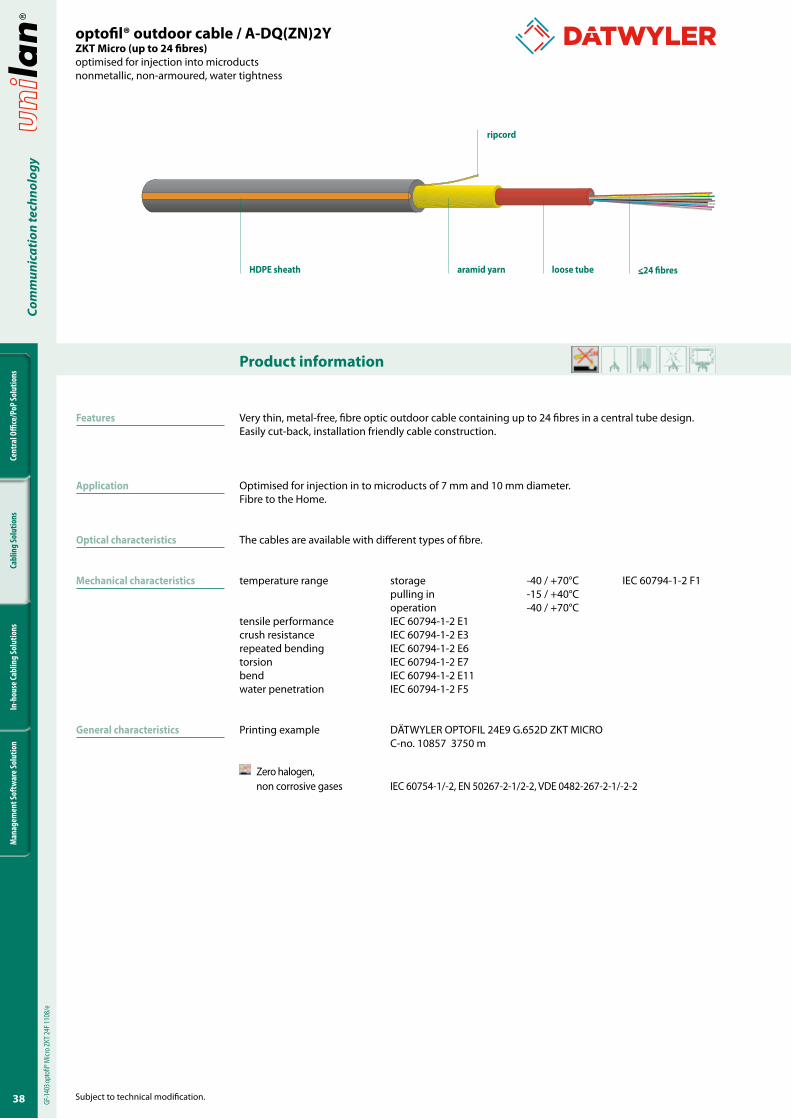
Very thin, metal-free, fibre optic outdoor cable containing up to 24 fibres in a central tube design.Easily cut-back, installation friendly cable construction.
Optimised for injection in to microducts of 7 mm and 10 mm diameter.Fibre to the Home.
The cables are available with different types of fibre.
temperature range storage -40 / +70°C IEC 60794-1-2 F1 pulling in -15 / +40°C operation -40 / +70°Ctensile performance IEC 60794-1-2 E1crush resistance IEC 60794-1-2 E3repeated bending IEC 60794-1-2 E6torsion IEC 60794-1-2 E7bend IEC 60794-1-2 E11water penetration IEC 60794-1-2 F5
Printing example DÄTWYLER OPTOFIL 24E9 G.652D ZKT MICRO C-no. 10857 3750 m
Zero halogen, non corrosive gases IEC 60754-1/-2, EN 50267-2-1/2-2, VDE 0482-267-2-1/-2-2
optofil® outdoor cable / A-DQ(ZN)2YZKT Micro (up to 24 fibres)optimised for injection into microductsnonmetallic, non-armoured, water tightness
GF-14
03 op
tofil®
Micr
o ZK
T 24F
1108
/e
loose tubeHDPE sheath aramid yarn
ripcord
<24 fibres
39
Cent
ral O
ffice
/PoP
Solu
tions
Cabl
ing
Solu
tions
In-h
ouse
Cabl
ing
Solu
tions
Man
agem
ent S
oftw
are S
olut
ion
Com
mun
icat
ion
tech
nolo
gy
Subject to technical modification.
optofil® outdoor cable / A-DQ(ZN)2YZKT Micro (up to 24 fibres)optimised for injection into microductsnonmetallic, non-armoured, water tightness
Versions
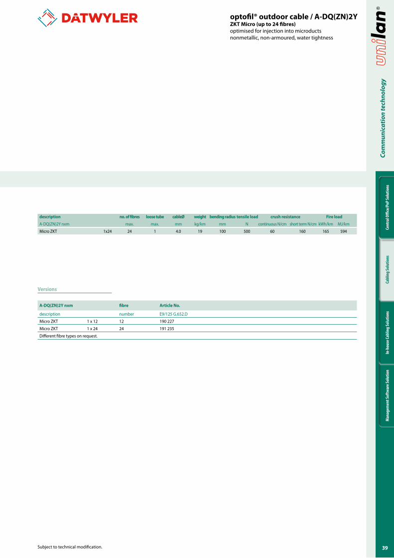
description no. of fibres loose tube cableØ weight bending radius tensile load crush resistance Fire load
A-DQ(ZN)2Y nxm max. max. mm kg/km mm N continuous N/cm short term N/cm kWh/km MJ/km
Micro ZKT 1x24 24 1 4.0 19 100 500 60 160 165 594
A-DQ(ZN)2Y nxm fibre Article No.
description number E9/125 G.652.D
Micro ZKT 1 x 12 12 190 227
Micro ZKT 1 x 24 24 191 235
Different fibre types on request.
40
Cent
ral O
ffice
/PoP
Solu
tions
Cabl
ing
Solu
tions
In-h
ouse
Cabl
ing
Solu
tions
Man
agem
ent S
oftw
are S
olut
ion
Com
mun
icat
ion
tech
nolo
gy
Product information
Subject to technical modification.
Features
Application
Optical characteristics
Mechanical characteristics
General characteristics
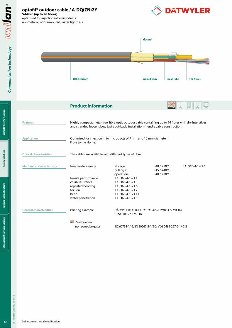
Highly compact, metal-free, fibre optic outdoor cable containing up to 96 fibres with dry interstices and stranded loose tubes. Easily cut-back, installation-friendly cable construction.
Optimised for injection in to microducts of 7 mm and 10 mm diameter.Fibre to the Home.
The cables are available with different types of fibre.
temperature range storage -40 / +70°C IEC 60794-1-2 F1 pulling in -15 / +40°C operation -40 / +70°Ctensile performance IEC 60794-1-2 E1crush resistance IEC 60794-1-2 E3repeated bending IEC 60794-1-2 E6torsion IEC 60794-1-2 E7bend IEC 60794-1-2 E11water penetration IEC 60794-1-2 F5
Printing example DÄTWYLER OPTOFIL 96E9 G.652D WBKT S-MICRO C-no. 10857 3750 m
Zero halogen, non corrosive gases IEC 60754-1/-2, EN 50267-2-1/2-2, VDE 0482-267-2-1/-2-2
optofil® outdoor cable / A-DQ(ZN)2YS-Micro (up to 96 fibres)optimised for injection into microductsnonmetallic, non-armoured, water tightness
loose tubeHDPE sheath aramid yarn
ripcord
<�2 fibres
GF-14
04 op
tofil®
Micr
o wbK
T 96F
0111
/e
4�
Cent
ral O
ffice
/PoP
Solu
tions
Cabl
ing
Solu
tions
In-h
ouse
Cabl
ing
Solu
tions
Man
agem
ent S
oftw
are S
olut
ion
Com
mun
icat
ion
tech
nolo
gy
Subject to technical modification.
optofil® outdoor cable / A-DQ(ZN)2YS-Micro (up to 96 fibres)optimised for injection into microductsnonmetallic, non-armoured, water tightness
Versions
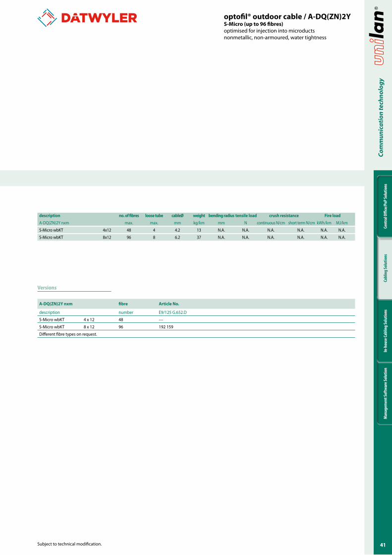
description no. of fibres loose tube cableØ weight bending radius tensile load crush resistance Fire load
A-DQ(ZN)2Y nxm max. max. mm kg/km mm N continuous N/cm short term N/cm kWh/km MJ/km
S-Micro wbKT 4x12 48 4 4.2 13 N.A. N.A. N.A. N.A. N.A. N.A.
S-Micro wbKT 8x12 96 8 6.2 37 N.A. N.A. N.A. N.A. N.A. N.A.
A-DQ(ZN)2Y nxm fibre Article No.
description number E9/125 G.652.D
S-Micro wbKT 4 x 12 48 ––
S-Micro wbKT 8 x 12 96 192 159
Different fibre types on request.
42
Cent
ral O
ffice
/PoP
Solu
tions
Cabl
ing
Solu
tions
In-h
ouse
Cabl
ing
Solu
tions
Man
agem
ent S
oftw
are S
olut
ion
Com
mun
icat
ion
tech
nolo
gy
Product information
Subject to technical modification.
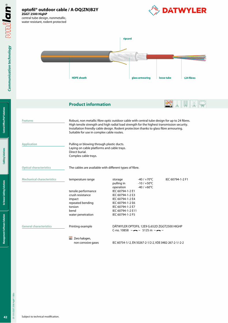
Robust, non metallic fibre optic outdoor cable with central tube design for up to 24 fibres. High tensile strength and high radial load strength for the highest transmission security. Installation friendly cable design. Rodent protection thanks to glass fibre armouring. Suitable for use in complex cable routes.
Pulling or blowing through plastic ducts.Laying on cable platforms and cable trays.Direct burial.Complex cable trays.
The cables are available with different types of fibre.
temperature range storage -40 / +70°C IEC 60794-1-2 F1 pulling in -10 / +50°C operation -40 / +60°Ctensile performance IEC 60794-1-2 E1crush resistance IEC 60794-1-2 E3impact IEC 60794-1-2 E4repeated bending IEC 60794-1-2 E6torsion IEC 60794-1-2 E7bend IEC 60794-1-2 E11water penetration IEC 60794-1-2 F5
Printing example DÄTWYLER OPTOFIL 12E9 G.652D ZGGT2500 HIGHP C-no. 10858 ~ ~ 5125 m ~ ~
Zero halogen, non corrosive gases IEC 60754-1/-2, EN 50267-2-1/2-2, VDE 0482-267-2-1/-2-2
optofil® outdoor cable / A-DQ(ZN)B2YZGGT 2�00 HighPcentral tube design, nonmetallic, water resistant, rodent protected
loose tubeHDPE sheath glass armouring
ripcord
GF-1
310 Z
GGT 2
500 H
ighP
1108
/e
Features
Application
Optical characteristics
Mechanical characteristics
General characteristics
<24 fibres

43
Cent
ral O
ffice
/PoP
Solu
tions
Cabl
ing
Solu
tions
In-h
ouse
Cabl
ing
Solu
tions
Man
agem
ent S
oftw
are S
olut
ion
Com
mun
icat
ion
tech
nolo
gy
Subject to technical modification.
Versions
A-DQ(ZN)B2Y �xm fibre Article No.
description number E9/125 G.652.D
ZGGT 2500 HighP 1 x 4 4 190 166
ZGGT 2500 HighP 1 x 6 6 190 167
ZGGT 2500 HighP 1 x 8 8 190 168
ZGGT 2500 HighP 1 x 12 12 190 169
ZGGT 2500 HighP 1 x 24 24 190 149
Different fibre types on request.
description no. of fibres loose tube cableØ weight bending radius tensile load crush resistance Fire load
A-DQ(ZN)B2Y 1xm max. max. mm kg/km mm N continuous N/cm short term N/cm kWh/km MJ/km
ZGGT 2500 HighP 1x12 12 1 8.5 65 130 2500 600 1000 558 2009
ZGGT 2500 HighP 1x24 24 1 9.0 70 135 2500 600 1000 589 2120
optofil® outdoor cable / A-DQ(ZN)B2YZGGT 2�00 HighPcentral tube design, nonmetallic, water resistant, rodent protected

44
Cent
ral O
ffice
/PoP
Solu
tions
Cabl
ing
Solu
tions
In-h
ouse
Cabl
ing
Solu
tions
Man
agem
ent S
oftw
are S
olut
ion
Com
mun
icat
ion
tech
nolo
gy
Product information
Subject to technical modification.
Features
Application
Optical characteristics
Mechanical characteristics
General characteristics
Highly compact, metal-free, fibre optic outdoor cable containing up to 72 fibres with dry interstices and stranded loose tubes. Easily cut-back, installation-friendly cable construction.
Optimised for injection in to microducts of 7mm and 10mm diameter.Fibre to the Home.
The cables are available with different types of fibre.
temperature range storage -40 / +70°C IEC 60794-1-2 F1 pulling in -15 / +40°C operation -40 / +70°Ctensile performance IEC 60794-1-2 E1crush resistance IEC 60794-1-2 E3repeated bending IEC 60794-1-2 E6torsion IEC 60794-1-2 E7bend IEC 60794-1-2 E11water penetration IEC 60794-1-2 F5
Printing example DÄTWYLER OPTOFIL 72E9 G.652D WBKT MICRO C-no. 10857 3750 m
Zero halogen, non corrosive gases IEC 60754-1/-2, EN 50267-2-1/2-2, VDE 0482-267-2-1/-2-2
optofil® outdoor cable / A-DQ(ZN)2YwbKT Micro (up to �2 fibres)nonmetallic, non-armoured, dry interstices, water tightness
GF-14
04 op
tofil®
Micr
o wbK
T 60F
1108
/e
loose tubeHDPE sheath aramid yarn
ripcord
<�2 fibres
4�
Cent
ral O
ffice
/PoP
Solu
tions
Cabl
ing
Solu
tions
In-h
ouse
Cabl
ing
Solu
tions
Man
agem
ent S
oftw
are S
olut
ion
Com
mun
icat
ion
tech
nolo
gy
Subject to technical modification.
Versions
description no. of fibres loose tube cableØ weight bending radius tensile load crush resistance Fire load
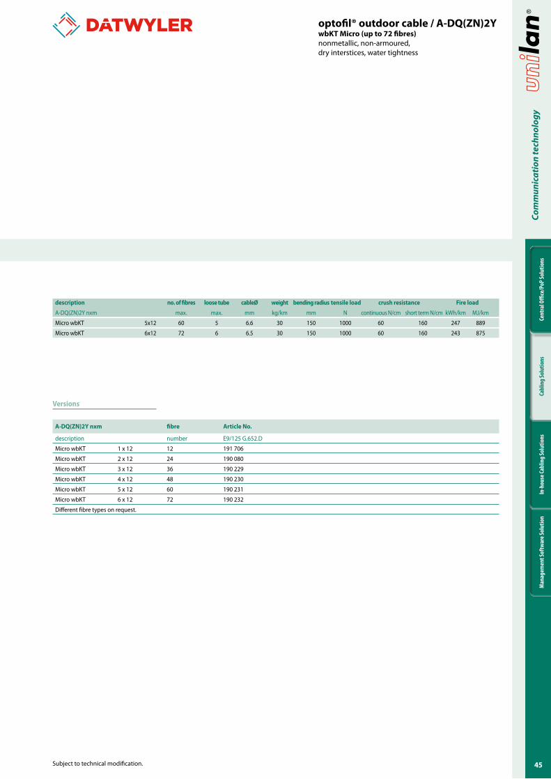
A-DQ(ZN)2Y nxm max. max. mm kg/km mm N continuous N/cm short term N/cm kWh/km MJ/km
Micro wbKT 5x12 60 5 6.6 30 150 1000 60 160 247 889
Micro wbKT 6x12 72 6 6.5 30 150 1000 60 160 243 875
A-DQ(ZN)2Y nxm fibre Article No.
description number E9/125 G.652.D
Micro wbKT 1 x 12 12 191 706
Micro wbKT 2 x 12 24 190 080
Micro wbKT 3 x 12 36 190 229
Micro wbKT 4 x 12 48 190 230
Micro wbKT 5 x 12 60 190 231
Micro wbKT 6 x 12 72 190 232
Different fibre types on request.
optofil® outdoor cable / A-DQ(ZN)2YwbKT Micro (up to �2 fibres)nonmetallic, non-armoured, dry interstices, water tightness
46
Cent
ral O
ffice
/PoP
Solu
tions
Cabl
ing
Solu
tions
In-h
ouse
Cabl
ing
Solu
tions
Man
agem
ent S
oftw
are S
olut
ion
Com
mun
icat
ion
tech
nolo
gy
Product information
Subject to technical modification.
Features
Application
Optical characteristics
Mechanical characteristics
General characteristics
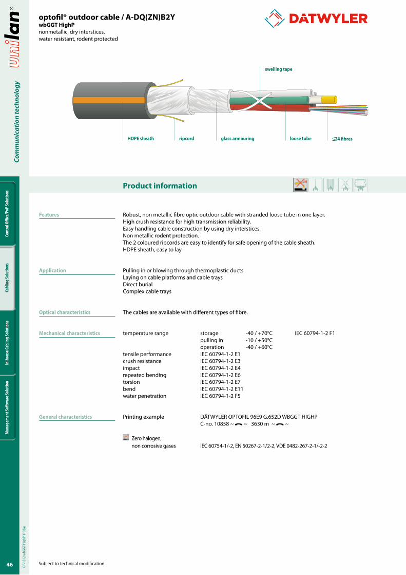
optofil® outdoor cable / A-DQ(ZN)B2YwbGGT HighPnonmetallic, dry interstices, water resistant, rodent protected
loose tuberipcordHDPE sheath
swelling tape
glass armouring
Robust, non metallic fibre optic outdoor cable with stranded loose tube in one layer.High crush resistance for high transmission reliability.Easy handling cable construction by using dry interstices.Non metallic rodent protection.The 2 coloured ripcords are easy to identify for safe opening of the cable sheath.HDPE sheath, easy to lay
Pulling in or blowing through thermoplastic ductsLaying on cable platforms and cable traysDirect burialComplex cable trays
The cables are available with different types of fibre.
temperature range storage -40 / +70°C IEC 60794-1-2 F1 pulling in -10 / +50°C operation -40 / +60°Ctensile performance IEC 60794-1-2 E1crush resistance IEC 60794-1-2 E3impact IEC 60794-1-2 E4repeated bending IEC 60794-1-2 E6torsion IEC 60794-1-2 E7bend IEC 60794-1-2 E11water penetration IEC 60794-1-2 F5
Printing example DÄTWYLER OPTOFIL 96E9 G.652D WBGGT HIGHP C-no. 10858 ~ ~ 3630 m ~ ~
Zero halogen, non corrosive gases IEC 60754-1/-2, EN 50267-2-1/2-2, VDE 0482-267-2-1/-2-2
GF-1
312 w
bGGT
Hig
hP 11
08/e
<24 fibres

4�
Cent
ral O
ffice
/PoP
Solu
tions
Cabl
ing
Solu
tions
In-h
ouse
Cabl
ing
Solu
tions
Man
agem
ent S
oftw
are S
olut
ion
Com
mun
icat
ion
tech
nolo
gy
Subject to technical modification.
optofil® outdoor cable / A-DQ(ZN)B2YwbGGT HighPnonmetallic, dry interstices, water resistant, rodent protected
Versions
description no. of fibres loose tube cableØ weight bending radius tensile load crush resistance Fire load
A-DQ(ZN)B2Y nxm max. max. mm kg/km mm N continuous N/cm short term N/cm kWh/km MJ/km
wbGGT5 HighP 60 5 12.0 126 180 9000 300 800 1040 3744
wbGGT6 HighP 72 6 12.8 146 195 9000 300 800 1137 4093
wbGGT8 HighP 96 8 14.0 170 210 9000 300 800 1305 5033
wbGGT10 HighP 120 10 15.4 200 230 9000 300 800 1491 5368
wbGGT12 HighP 144 12 16.9 237 255 9000 300 800 1707 6145
wbGGT6 HighP 144 6 13.8 167 205 9000 300 800 1291 4655
wbGGT8 HighP 192 8 15.0 199 225 9000 300 800 1570 5661
wbGGT10 HighP 240 10 17.0 250 255 9000 300 800 1962 7175
wbGGT12 HighP 288 12 18.8 292 285 9000 300 800 2422 8719
A-DQ(ZN)B2Y nxm fibre Article No.
description number E9/125 G.652.D
wbGGT5 HighP 1 x 12 12 190 059
wbGGT5 HighP 2 x 12 24 186 748
wbGGT5 HighP 3 x 12 36 190 058
wbGGT5 HighP 4 x 12 48 187 385
wbGGT5 HighP 5 x 12 60 190 171
wbGGT6 HighP 6 x 12 72 190 172
wbGGT8 HighP 8 x 12 96 186 760
wbGGT10 HighP 10 x 12 120 190 175
wbGGT12 HighP 12 x 12 144 187 394
wbGGT6 HighP 6 x 24 144 190 764
wbGGT8 HighP 8 x 24 192 191 270
wbGGT10 HighP 9 x 24 216 190 696
wbGGT10 HighP 10 x 24 240 190 109
wbGGT12 HighP 12 x 24 288 190 325
Different fibre types on request.
48
Cent
ral O
ffice
/PoP
Solu
tions
Cabl
ing
Solu
tions
In-h
ouse
Cabl
ing
Solu
tions
Man
agem
ent S
oftw
are S
olut
ion
Com
mun
icat
ion
tech
nolo
gy
Product information
Subject to technical modification.
Features
Application
Optical characteristics
Mechanical characteristics
General characteristics
Compact, fibre optic outdoor cable ≤ 576 fibres for city and access network applications. Easy handling cable construction by using dry interstices.Non metallic rodent protection.The 2 couloured ripcords are easy to indentify for safe opening of the cable sheath.HDPE sheath, easy to lay.
Optimised for injection into compact thermoplastic ducts K28/D32 (design 18x12) and K44/D40 (design 18x24, 24x12).
The cables are avaiable with different types of fibre.
temperature range storage -40 / +70°C IEC 60794-1-2 F1 pulling in -10 / +50°C operation -40 / +60°Ctensile performance IEC 60794-1-2 E1crush resistance IEC 60794-1-2 E3repeated bending IEC 60794-1-2 E6torsion IEC 60794-1-2 E7bending IEC 60794-1-2 E11water penetration IEC 60794-1-2 F5
Printing example DÄTWYLER OPTOFIL 216E9 G.652D WBGGT HIGHP C-no. 10859 ~ ~ 2550 m ~ ~
Zero halogen, non corrosive gases IEC 60754-1/-2, EN 50267-2-1/2-2, VDE 0482-267-2-1/-2-2
optofil® outdoor cable / A-DQ(ZN)B2YwbGGT HighP (City Compact)nonmetallic, dry interstices,water resistant, rodent protected
GF-1
327 w
bGGT
2L H
P (cc
) 110
8/e
loose tubesHDPE sheath glass armouring
swelling tape
ripcord <24 fibres
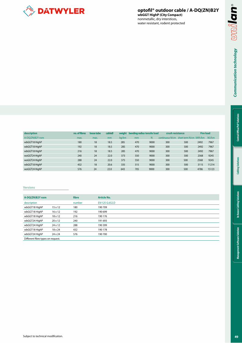
49
Cent
ral O
ffice
/PoP
Solu
tions
Cabl
ing
Solu
tions
In-h
ouse
Cabl
ing
Solu
tions
Man
agem
ent S
oftw
are S
olut
ion
Com
mun
icat
ion
tech
nolo
gy
Subject to technical modification.
Versions
description no. of fibres loose tube cableØ weight bending radius tensile load crush resistance Fire load
A-DQ(ZN)B2Y nxm max. max. mm kg/km mm N continuous N/cm short term N/cm kWh/km MJ/km
wbGGT18 HighP 180 18 18.5 285 470 9000 300 500 2492 7967
wbGGT18 HighP 192 18 18.5 285 470 9000 300 500 2492 7967
wbGGT18 HighP 216 18 18.5 285 470 9000 300 500 2492 7967
woGGT24 HighP 240 24 22.0 373 550 9000 300 500 2568 9245
woGGT24 HighP 288 24 22.0 375 550 9000 300 500 2568 9245
wbGGT18 HighP 432 18 20.6 335 515 9000 300 500 3115 11214
woGGT24 HighP 576 24 22.0 643 705 9000 300 500 4786 15123
A-DQ(ZN)B2Y nxm fibre Article No.
description number E9/125 G.652.D
wbGGT18 HighP 15 x 12 180 190 709
wbGGT18 HighP 16 x 12 192 190 699
wbGGT18 HighP 18 x 12 216 190 176
wbGGT24 HighP 20 x 12 240 191 693
wbGGT24 HighP 24 x 12 288 190 399
wbGGT18 HighP 18 x 24 432 190 178
wbGGT24 HighP 24 x 24 576 190 700
Different fibre types on request.
optofil® outdoor cable / A-DQ(ZN)B2YwbGGT HighP (City Compact)nonmetallic, dry interstices,water resistant, rodent protected
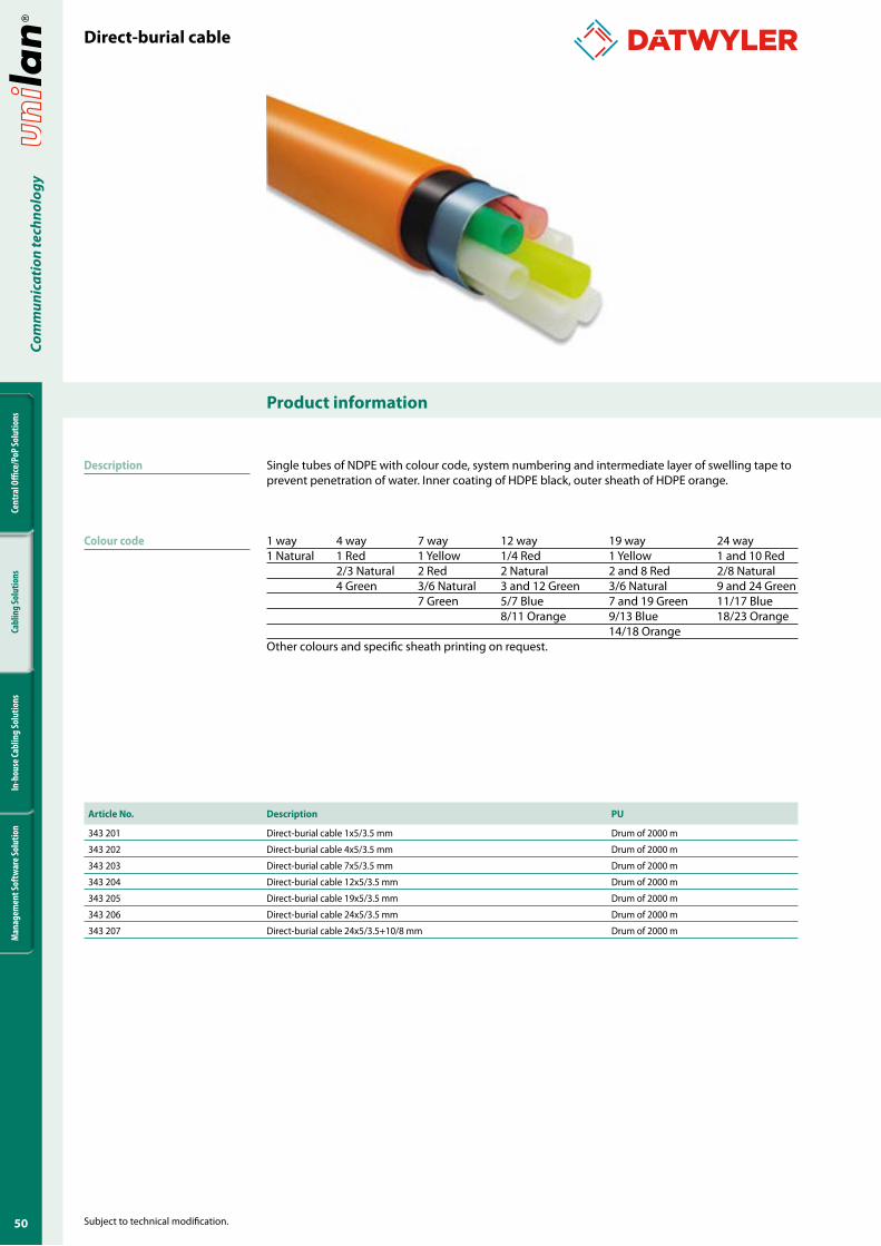
�0
Cent
ral O
ffice
/PoP
Solu
tions
Cabl
ing
Solu
tions
In-h
ouse
Cabl
ing
Solu
tions
Man
agem
ent S
oftw
are S
olut
ion
Com
mun
icat
ion
tech
nolo
gy
Product information
Subject to technical modification.
Description
Colour code
Single tubes of NDPE with colour code, system numbering and intermediate layer of swelling tape to prevent penetration of water. Inner coating of HDPE black, outer sheath of HDPE orange.
1 way 4 way 7 way 12 way 19 way 24 way1 Natural 1 Red 1 Yellow 1/4 Red 1 Yellow 1 and 10 Red 2/3 Natural 2 Red 2 Natural 2 and 8 Red 2/8 Natural 4 Green 3/6 Natural 3 and 12 Green 3/6 Natural 9 and 24 Green 7 Green 5/7 Blue 7 and 19 Green 11/17 Blue 8/11 Orange 9/13 Blue 18/23 Orange 14/18 Orange Other colours and specific sheath printing on request.
Direct-burial cable
Article No. Description PU
343 201 Direct-burial cable 1x5/3.5 mm Drum of 2000 m
343 202 Direct-burial cable 4x5/3.5 mm Drum of 2000 m
343 203 Direct-burial cable 7x5/3.5 mm Drum of 2000 m
343 204 Direct-burial cable 12x5/3.5 mm Drum of 2000 m
343 205 Direct-burial cable 19x5/3.5 mm Drum of 2000 m
343 206 Direct-burial cable 24x5/3.5 mm Drum of 2000 m
343 207 Direct-burial cable 24x5/3.5+10/8 mm Drum of 2000 m
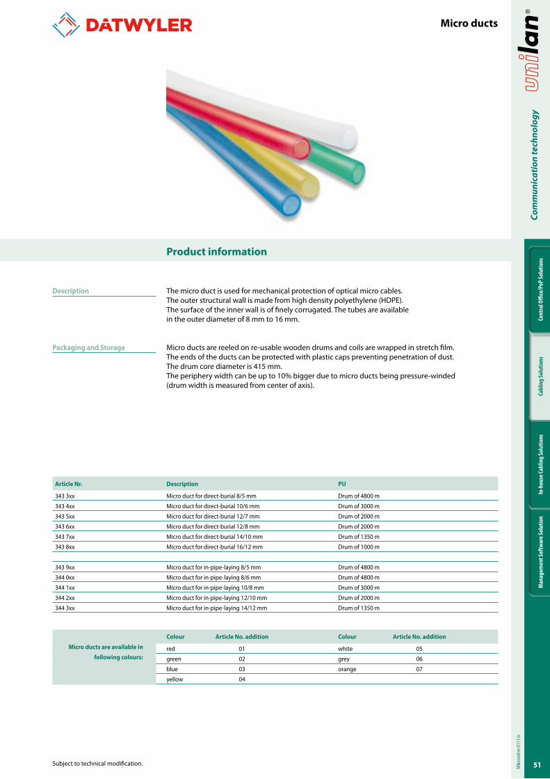
��
Cent
ral O
ffice
/PoP
Solu
tions
Cabl
ing
Solu
tions
In-h
ouse
Cabl
ing
Solu
tions
Man
agem
ent S
oftw
are S
olut
ion
Com
mun
icat
ion
tech
nolo
gy
Subject to technical modification.
Product information
Article Nr. Description PU
343 3xx Micro duct for direct-burial 8/5 mm Drum of 4800 m
343 4xx Micro duct for direct-burial 10/6 mm Drum of 3000 m
343 5xx Micro duct for direct-burial 12/7 mm Drum of 2000 m
343 6xx Micro duct for direct-burial 12/8 mm Drum of 2000 m
343 7xx Micro duct for direct-burial 14/10 mm Drum of 1350 m
343 8xx Micro duct for direct-burial 16/12 mm Drum of 1000 m
343 9xx Micro duct for in-pipe-laying 8/5 mm Drum of 4800 m
344 0xx Micro duct for in-pipe-laying 8/6 mm Drum of 4800 m
344 1xx Micro duct for in-pipe-laying 10/8 mm Drum of 3000 m
344 2xx Micro duct for in-pipe-laying 12/10 mm Drum of 2000 m
344 3xx Micro duct for in-pipe-laying 14/12 mm Drum of 1350 m
Colour Article No. addition Colour Article No. addition
red 01 white 05
green 02 grey 06
blue 03 orange 07
yellow 04
Description
Packaging and Storage
The micro duct is used for mechanical protection of optical micro cables. The outer structural wall is made from high density polyethylene (HDPE). The surface of the inner wall is of finely corrugated. The tubes are available in the outer diameter of 8 mm to 16 mm.
Micro ducts are reeled on re-usable wooden drums and coils are wrapped in stretch film. The ends of the ducts can be protected with plastic caps preventing penetration of dust. The drum core diameter is 415 mm. The periphery width can be up to 10% bigger due to micro ducts being pressure-winded (drum width is measured from center of axis).
Micro ducts
Mikr
oroh
re 01
11/e
Micro ducts are available in
following colours:
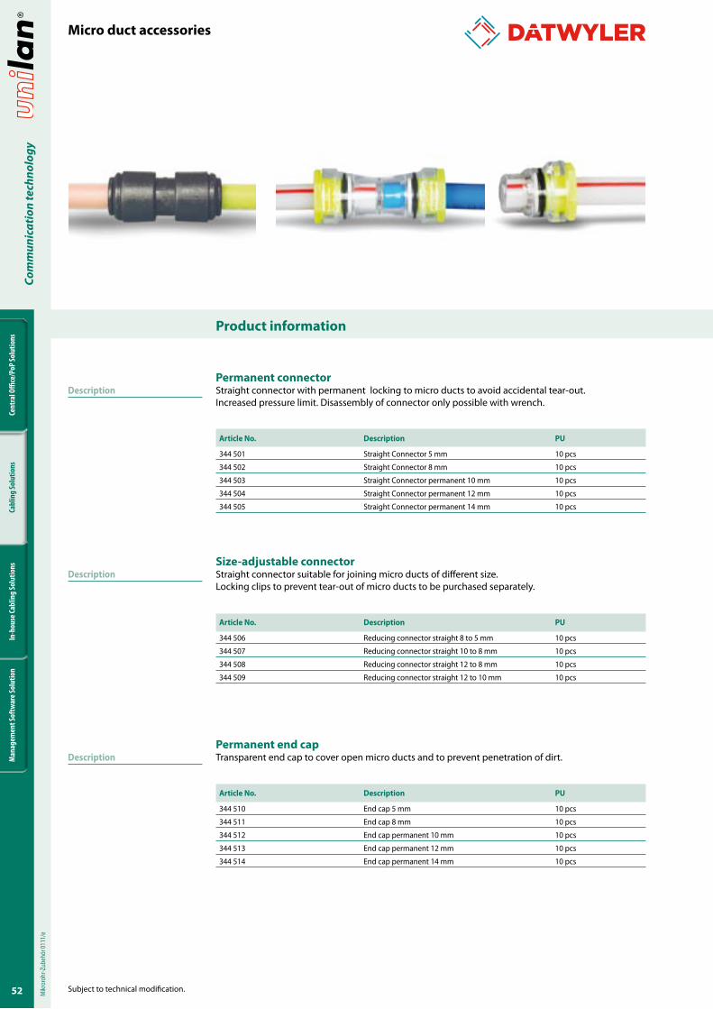
�2
Cent
ral O
ffice
/PoP
Solu
tions
Cabl
ing
Solu
tions
In-h
ouse
Cabl
ing
Solu
tions
Man
agem
ent S
oftw
are S
olut
ion
Com
mun
icat
ion
tech
nolo
gy
Product information
Subject to technical modification.
DescriptionPermanent connectorStraight connector with permanent locking to micro ducts to avoid accidental tear-out. Increased pressure limit. Disassembly of connector only possible with wrench.
Article No. Description PU
344 501 Straight Connector 5 mm 10 pcs
344 502 Straight Connector 8 mm 10 pcs
344 503 Straight Connector permanent 10 mm 10 pcs
344 504 Straight Connector permanent 12 mm 10 pcs
344 505 Straight Connector permanent 14 mm 10 pcs
Size-adjustable connectorStraight connector suitable for joining micro ducts of different size.Locking clips to prevent tear-out of micro ducts to be purchased separately.
Article No. Description PU
344 506 Reducing connector straight 8 to 5 mm 10 pcs
344 507 Reducing connector straight 10 to 8 mm 10 pcs
344 508 Reducing connector straight 12 to 8 mm 10 pcs
344 509 Reducing connector straight 12 to 10 mm 10 pcs
Permanent end capTransparent end cap to cover open micro ducts and to prevent penetration of dirt.
Article No. Description PU
344 510 End cap 5 mm 10 pcs
344 511 End cap 8 mm 10 pcs
344 512 End cap permanent 10 mm 10 pcs
344 513 End cap permanent 12 mm 10 pcs
344 514 End cap permanent 14 mm 10 pcs
Micro duct accessoriesM
ikror
ohr-Z
ubeh
ör 01
11/e
Description
Description
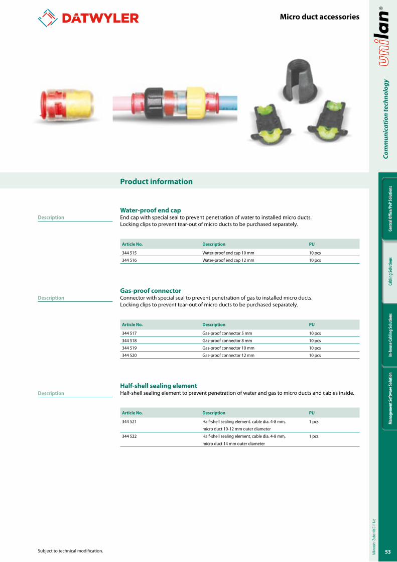
�3
Cent
ral O
ffice
/PoP
Solu
tions
Cabl
ing
Solu
tions
In-h
ouse
Cabl
ing
Solu
tions
Man
agem
ent S
oftw
are S
olut
ion
Com
mun
icat
ion
tech
nolo
gy
Subject to technical modification.
Product information
DescriptionWater-proof end capEnd cap with special seal to prevent penetration of water to installed micro ducts.Locking clips to prevent tear-out of micro ducts to be purchased separately.
Article No. Description PU
344 515 Water-proof end cap 10 mm 10 pcs
344 516 Water-proof end cap 12 mm 10 pcs
Gas-proof connectorConnector with special seal to prevent penetration of gas to installed micro ducts.Locking clips to prevent tear-out of micro ducts to be purchased separately.
Article No. Description PU
344 517 Gas-proof connector 5 mm 10 pcs
344 518 Gas-proof connector 8 mm 10 pcs
344 519 Gas-proof connector 10 mm 10 pcs
344 520 Gas-proof connector 12 mm 10 pcs
Half-shell sealing elementHalf-shell sealing element to prevent penetration of water and gas to micro ducts and cables inside.
Article No. Description PU
344 521 Half-shell sealing element. cable dia. 4-8 mm, 1 pcs
micro duct 10-12 mm outer diameter
344 522 Half-shell sealing element, cable dia. 4-8 mm, 1 pcs
micro duct 14 mm outer diameter
Micro duct accessories
Mikr
oroh
r-Zub
ehör
0111
/e
Description
Description
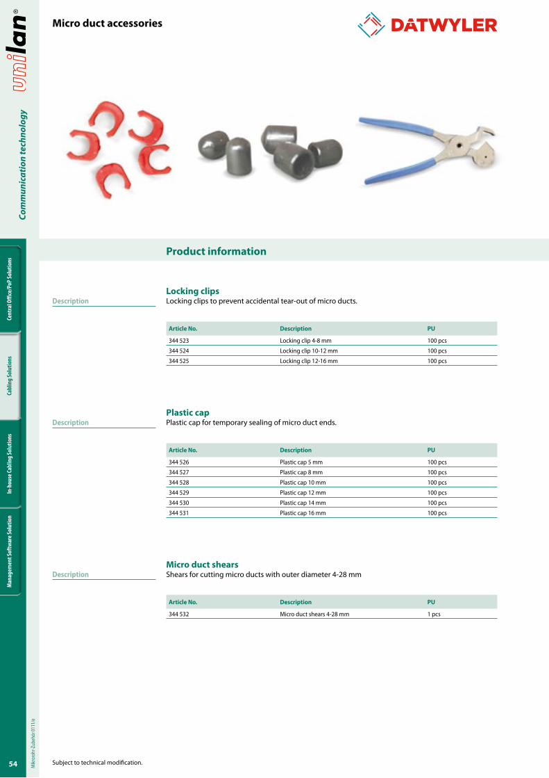
�4
Cent
ral O
ffice
/PoP
Solu
tions
Cabl
ing
Solu
tions
In-h
ouse
Cabl
ing
Solu
tions
Man
agem
ent S
oftw
are S
olut
ion
Com
mun
icat
ion
tech
nolo
gy
Product information
Subject to technical modification.
DescriptionLocking clipsLocking clips to prevent accidental tear-out of micro ducts.
Article No. Description PU
344 523 Locking clip 4-8 mm 100 pcs
344 524 Locking clip 10-12 mm 100 pcs
344 525 Locking clip 12-16 mm 100 pcs
Plastic capPlastic cap for temporary sealing of micro duct ends.
Article No. Description PU
344 526 Plastic cap 5 mm 100 pcs
344 527 Plastic cap 8 mm 100 pcs
344 528 Plastic cap 10 mm 100 pcs
344 529 Plastic cap 12 mm 100 pcs
344 530 Plastic cap 14 mm 100 pcs
344 531 Plastic cap 16 mm 100 pcs
Micro duct shearsShears for cutting micro ducts with outer diameter 4-28 mm
Article No. Description PU
344 532 Micro duct shears 4-28 mm 1 pcs
Micro duct accessoriesM
ikror
ohr-Z
ubeh
ör 01
11/e
Description
Description
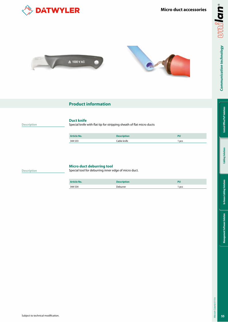
��
Cent
ral O
ffice
/PoP
Solu
tions
Cabl
ing
Solu
tions
In-h
ouse
Cabl
ing
Solu
tions
Man
agem
ent S
oftw
are S
olut
ion
Com
mun
icat
ion
tech
nolo
gy
Subject to technical modification.
Product information
DescriptionDuct knifeSpecial knife with flat tip for stripping sheath of flat micro ducts
Article No. Description PU
344 533 Cable knife 1 pcs
Micro duct deburring toolSpecial tool for deburring inner edge of micro duct.
Article No. Description PU
344 534 Deburrer 1 pcs
Micro duct accessories
Mikr
oroh
r-Zub
ehör
0111
/e
Description
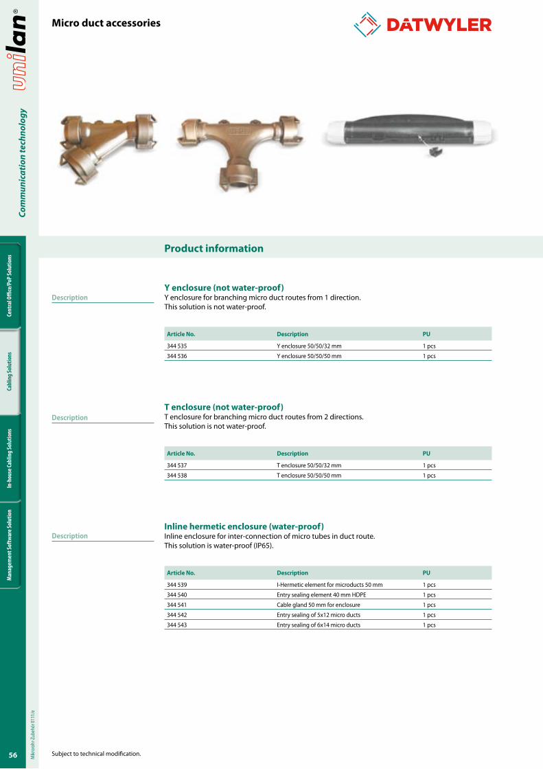
�6
Cent
ral O
ffice
/PoP
Solu
tions
Cabl
ing
Solu
tions
In-h
ouse
Cabl
ing
Solu
tions
Man
agem
ent S
oftw
are S
olut
ion
Com
mun
icat
ion
tech
nolo
gy
Product information
Subject to technical modification.
DescriptionY enclosure (not water-proof)Y enclosure for branching micro duct routes from 1 direction. This solution is not water-proof.
Article No. Description PU
344 535 Y enclosure 50/50/32 mm 1 pcs
344 536 Y enclosure 50/50/50 mm 1 pcs
T enclosure (not water-proof)T enclosure for branching micro duct routes from 2 directions.This solution is not water-proof.
Article No. Description PU
344 537 T enclosure 50/50/32 mm 1 pcs
344 538 T enclosure 50/50/50 mm 1 pcs
Inline hermetic enclosure (water-proof)Inline enclosure for inter-connection of micro tubes in duct route.This solution is water-proof (IP65).
Article No. Description PU
344 539 I-Hermetic element for microducts 50 mm 1 pcs
344 540 Entry sealing element 40 mm HDPE 1 pcs
344 541 Cable gland 50 mm for enclosure 1 pcs
344 542 Entry sealing of 5x12 micro ducts 1 pcs
344 543 Entry sealing of 6x14 micro ducts 1 pcs
Micro duct accessoriesM
ikror
ohr-Z
ubeh
ör 01
11/e
Description
Description
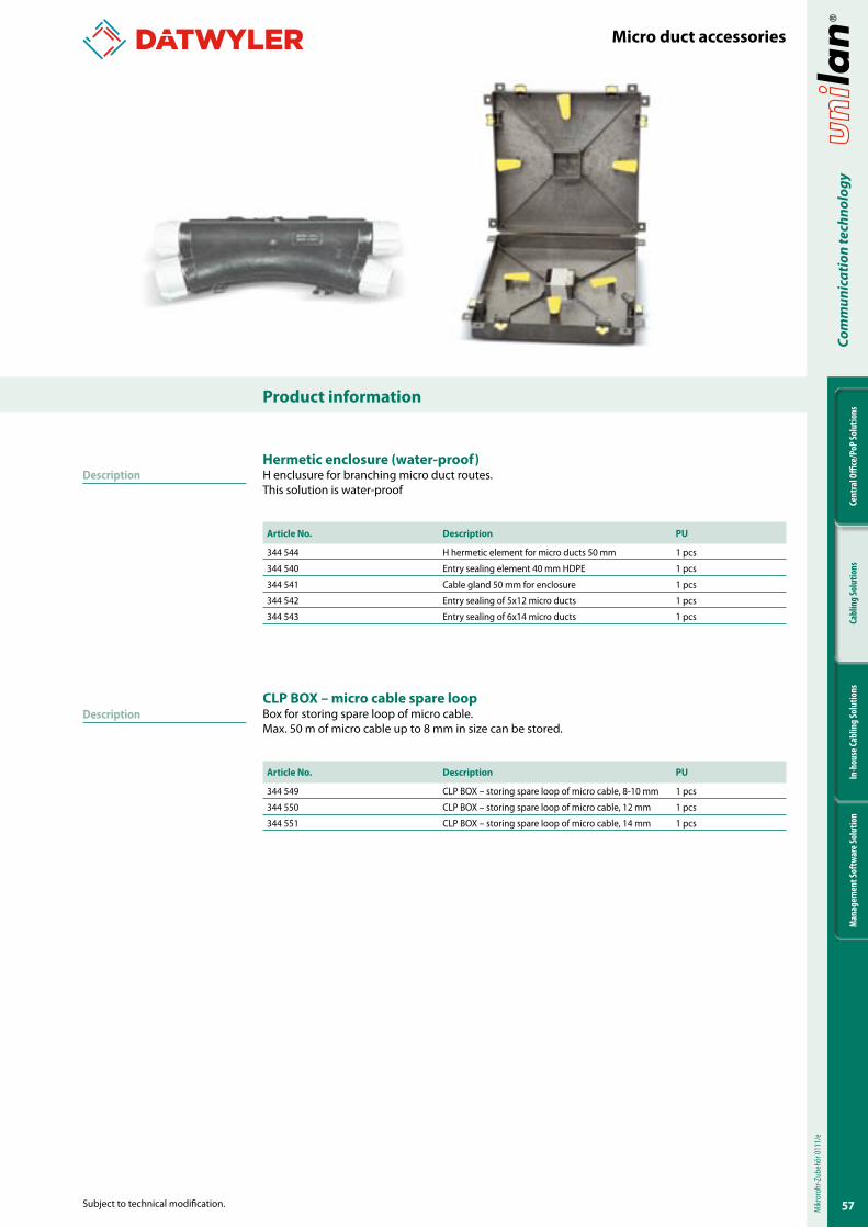
��
Cent
ral O
ffice
/PoP
Solu
tions
Cabl
ing
Solu
tions
In-h
ouse
Cabl
ing
Solu
tions
Man
agem
ent S
oftw
are S
olut
ion
Com
mun
icat
ion
tech
nolo
gy
Subject to technical modification.
Product information
Micro duct accessories
Hermetic enclosure (water-proof)H enclusure for branching micro duct routes.This solution is water-proof
Article No. Description PU
344 544 H hermetic element for micro ducts 50 mm 1 pcs
344 540 Entry sealing element 40 mm HDPE 1 pcs
344 541 Cable gland 50 mm for enclosure 1 pcs
344 542 Entry sealing of 5x12 micro ducts 1 pcs
344 543 Entry sealing of 6x14 micro ducts 1 pcs
CLP BOX – micro cable spare loopBox for storing spare loop of micro cable.Max. 50 m of micro cable up to 8 mm in size can be stored.
Article No. Description PU
344 549 CLP BOX – storing spare loop of micro cable, 8-10 mm 1 pcs
344 550 CLP BOX – storing spare loop of micro cable, 12 mm 1 pcs
344 551 CLP BOX – storing spare loop of micro cable, 14 mm 1 pcsM
ikror
ohr-Z
ubeh
ör 01
11/e
Description
Description
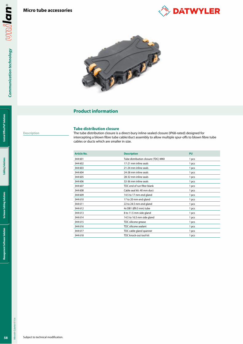
�8
Cent
ral O
ffice
/PoP
Solu
tions
Cabl
ing
Solu
tions
In-h
ouse
Cabl
ing
Solu
tions
Man
agem
ent S
oftw
are S
olut
ion
Com
mun
icat
ion
tech
nolo
gy
Product information
Subject to technical modification.
DescriptionTube distribution closureThe tube distribution closure is a direct-bury inline-sealed closure (IP68-rated) designed for intercepting a blown fibre tube cable/duct assembly to allow multiple spur-offs to blown fibre tube cables or ducts which are smaller in size.
Article No. Description PU
344 601 Tube distribution closure (TDC) MKII 1 pcs
344 602 17-21 mm inline seals 1 pcs
344 603 21-24 mm inline seals 1 pcs
344 604 24-28 mm inline seals 1 pcs
344 605 28-32 mm inline seals 1 pcs
344 606 32-36 mm inline seals 1 pcs
344 607 TDC end of run filter blank 1 pcs
344 608 Cable seal kit: 40 mm duct 1 pcs
344 609 14.5 to 17 mm end gland 1 pcs
344 610 17 to 20 mm end gland 1 pcs
344 611 22 to 24.5 mm end gland 1 pcs
344 612 4x DB1 (Ø9.5 mm) tube 1 pcs
344 613 8 to 11.5 mm side gland 1 pcs
344 614 14.5 to 16.5 mm side gland 1 pcs
344 615 TDC silicone grease 1 pcs
344 616 TDC silicone sealant 1 pcs
344 617 TDC cable gland spanner 1 pcs
344 618 TDC knock-out tool kit 1 pcs
Micro tube accessoriesM
ikror
ohr-Z
ubeh
ör 01
11/e
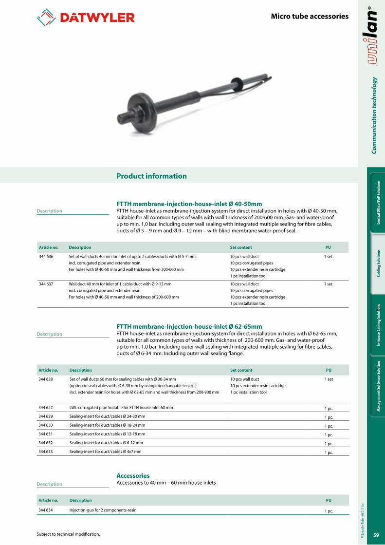
�9
Cent
ral O
ffice
/PoP
Solu
tions
Cabl
ing
Solu
tions
In-h
ouse
Cabl
ing
Solu
tions
Man
agem
ent S
oftw
are S
olut
ion
Com
mun
icat
ion
tech
nolo
gy
Subject to technical modification.
Product information
Description
Micro tube accessories
Mikr
oroh
r-Zub
ehör
0111
/e
Description
Description
FTTH membrane-injection-house-inlet Ø 40-�0mmFTTH house-inlet as membrane-injection-system for direct installation in holes with Ø 40-50 mm, suitable for all common types of walls with wall thickness of 200-600 mm. Gas- and water-proof up to min. 1,0 bar. Including outer wall sealing with integrated multiple sealing for fibre cables, ducts of Ø 5 – 9 mm and Ø 9 – 12 mm – with blind membrane water-proof seal.
FTTH membrane-Injection-house-inlet Ø 62-6�mmFTTH house-inlet as membrane-injection-system for direct installation in holes with Ø 62-65 mm, suitable for all common types of walls with thickness of 200-600 mm. Gas- and water-proof up to min. 1,0 bar. Including outer wall sealing with integrated multiple sealing for fibre cables, ducts of Ø 6-34 mm. Including outer wall sealing flange.
AccessoriesAccessories to 40 mm – 60 mm house inlets
Article no. Description Set content PU
344 636 Set of wall ducts 40 mm for inlet of up to 2 cables/ducts with Ø 5-7 mm, incl. corrugated pipe and extender resin.For holes with Ø 40-50 mm and wall thickness from 200-600 mm
10 pcs wall duct10 pcs corrugated pipes10 pcs extender resin cartridge1 pc installation tool
1 set
344 637 Wall duct 40 mm for inlet of 1 cable/duct with Ø 9-12 mmincl. corrugated pipe and extender resin.For holes with Ø 40-50 mm and wall thickness of 200-600 mm
10 pcs wall duct10 pcs corrugated pipes10 pcs extender resin cartridge1 pc installation tool
1 set
Article no. Description Set content PU
344 638 Set of wall ducts 60 mm for sealing cables with Ø 30-34 mm (option to seal cables with Ø 6-30 mm by using interchangable inserts) incl. extender resin For holes with Ø 62-65 mm and wall thickness from 200-900 mm
10 pcs wall duct10 pcs extender resin cartridge1 pc installation tool
1 set
344 627 LWL-corrugated pipe Suitable for FTTH house inlet 60 mm 1 pc.
344 629 Sealing-insert for duct/cables Ø 24-30 mm 1 pc.
344 630 Sealing-insert for duct/cables Ø 18-24 mm 1 pc.
344 631 Sealing-insert for duct/cables Ø 12-18 mm 1 pc.
344 632 Sealing-insert for duct/cables Ø 6-12 mm 1 pc.
344 633 Sealing-insert for duct/cables Ø 4x7 mm 1 pc.
Article no. Description PU
344 634 Injection-gun for 2 components-resin 1 pc.
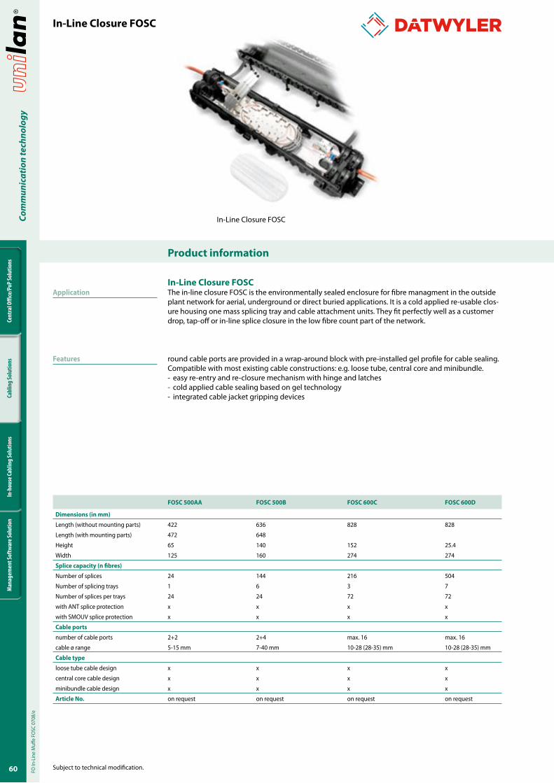
60
Cent
ral O
ffice
/PoP
Solu
tions
Cabl
ing
Solu
tions
In-h
ouse
Cabl
ing
Solu
tions
Man
agem
ent S
oftw
are S
olut
ion
Com
mun
icat
ion
tech
nolo
gy
Product information
Subject to technical modification.
In-Line Closure FOSC
In-Line Closure FOSCThe in-line closure FOSC is the environmentally sealed enclosure for fibre managment in the outside plant network for aerial, underground or direct buried applications. It is a cold applied re-usable clos-ure housing one mass splicing tray and cable attachment units. They fit perfectly well as a customer drop, tap-off or in-line splice closure in the low fibre count part of the network.
round cable ports are provided in a wrap-around block with pre-installed gel profile for cable sealing. Compatible with most existing cable constructions: e.g. loose tube, central core and minibundle.- easy re-entry and re-closure mechanism with hinge and latches- cold applied cable sealing based on gel technology- integrated cable jacket gripping devices
FOSC �00AA FOSC �00B FOSC 600C FOSC 600D
Dimensions (in mm)
Length (without mounting parts) 422 636 828 828
Length (with mounting parts) 472 648
Height 65 140 152 25.4
Width 125 160 274 274
Splice capacity (n fibres)
Number of splices 24 144 216 504
Number of splicing trays 1 6 3 7
Number of splices per trays 24 24 72 72
with ANT splice protection x x x x
with SMOUV splice protection x x x x
Cable ports
number of cable ports 2+2 2+4 max. 16 max. 16
cable ø range 5-15 mm 7-40 mm 10-28 (28-35) mm 10-28 (28-35) mm
Cable type
loose tube cable design x x x x
central core cable design x x x x
minibundle cable design x x x x
Article No. on request on request on request on request
In-Line Closure FOSC
FO In
-Lin
e M
uffe
FOSC
070
8/e
Application
Features
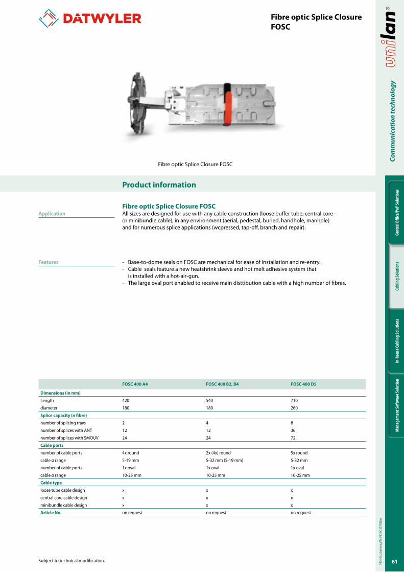
6�
Cent
ral O
ffice
/PoP
Solu
tions
Cabl
ing
Solu
tions
In-h
ouse
Cabl
ing
Solu
tions
Man
agem
ent S
oftw
are S
olut
ion
Com
mun
icat
ion
tech
nolo
gy
Subject to technical modification.
Product information
FO H
aube
nmuff
e FO
SC 0
708/
e
Application
Features
Fibre optic Splice ClosureFOSC
Fibre optic Splice Closure FOSCAll sizes are designed for use with any cable construction (loose buffer tube; central core - or minibundle cable), in any environment (aerial, pedestal, buried, handhole, manhole) and for numerous splice applications (wcpressed, tap-off, branch and repair).
- Base-to-dome seals on FOSC are mechanical for ease of installation and re-entry. - Cable seals feature a new heatshrink sleeve and hot melt adhesive system that is installed with a hot-air-gun.- The large oval port enabled to receive main disttibution cable with a high number of fibres.
FOSC 400 A4 FOSC 400 B2, B4 FOSC 400 D�
Dimensions (in mm)
Length 420 540 710
diameter 180 180 260
Splice capacity (n fibre)
number of splicing trays 2 4 8
number of splices with ANT 12 12 36
number of splices with SMOUV 24 24 72
Cable ports
number of cable ports 4x round 2x (4x) round 5x round
cable ø range 5-19 mm 5-32 mm (5-19 mm) 5-32 mm
number of cable ports 1x oval 1x oval 1x oval
cable ø range 10-25 mm 10-25 mm 10-25 mm
Cable type
loose tube cable design x x x
central core cable design x x x
minibundle cable design x x x
Article No. on request on request on request
Fibre optic Splice Closure FOSC
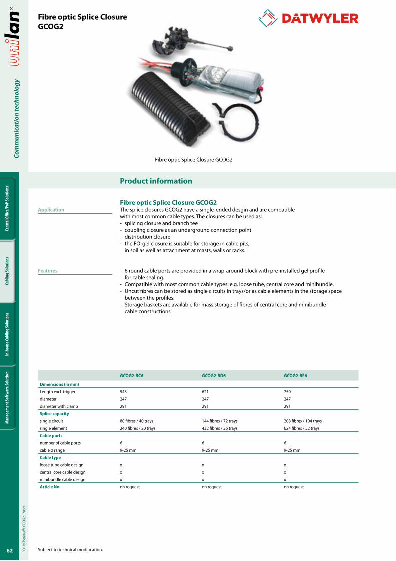
62
Cent
ral O
ffice
/PoP
Solu
tions
Cabl
ing
Solu
tions
In-h
ouse
Cabl
ing
Solu
tions
Man
agem
ent S
oftw
are S
olut
ion
Com
mun
icat
ion
tech
nolo
gy
Product information
Subject to technical modification.
Fibre optic Splice ClosureGCOG2
Fibre optic Splice Closure GCOG2The splice closures GCOG2 have a single-ended desgin and are compatible with most common cable types. The closures can be used as:- splicing closure and branch tee- coupling closure as an underground connection point- distribution closure- the FO-gel closure is suitable for storage in cable pits, in soil as well as attachment at masts, walls or racks.
- 6 round cable ports are provided in a wrap-around block with pre-installed gel profile for cable sealing. - Compatible with most common cable types: e.g. loose tube, central core and minibundle.- Uncut fibres can be stored as single circuits in trays/or as cable elements in the storage space between the profiles. - Storage baskets are available for mass storage of fibres of central core and minibundle cable constructions.
GCOG2-BC6 GCOG2-BD6 GCOG2-BE6
Dimensions (in mm)
Length excl. trigger 543 621 750
diameter 247 247 247
diameter with clamp 291 291 291
Splice capacity
single circuit 80 fibres / 40 trays 144 fibres / 72 trays 208 fibres / 104 trays
single element 240 fibres / 20 trays 432 fibres / 36 trays 624 fibres / 52 trays
Cable ports
number of cable ports 6 6 6
cable ø range 9-25 mm 9-25 mm 9-25 mm
Cable type
loose tube cable design x x x
central core cable design x x x
minibundle cable design x x x
Article No. on request on request on request
Fibre optic Splice Closure GCOG2
Application
Features
FO H
aube
nmuff
e GC
OG2
070
8/e
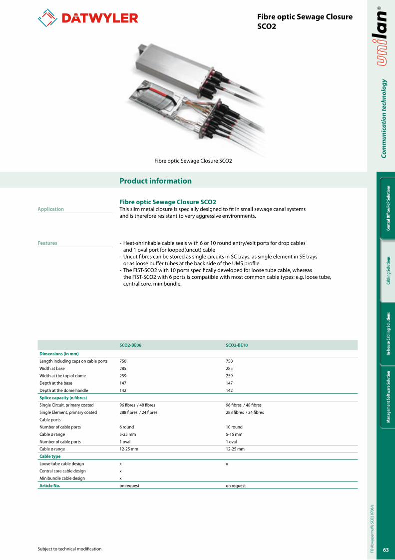
63
Cent
ral O
ffice
/PoP
Solu
tions
Cabl
ing
Solu
tions
In-h
ouse
Cabl
ing
Solu
tions
Man
agem
ent S
oftw
are S
olut
ion
Com
mun
icat
ion
tech
nolo
gy
Subject to technical modification.
Product information
Fibre optic Sewage ClosureSCO2
Fibre optic Sewage Closure SCO2This slim metal closure is specially designed to fit in small sewage canal systems and is therefore resistant to very aggressive environments.
- Heat-shrinkable cable seals with 6 or 10 round entry/exit ports for drop cables and 1 oval port for looped(uncut) cable
- Uncut fibres can be stored as single circuits in SC trays, as single element in SE trays or as loose buffer tubes at the back side of the UMS profile.
- The FIST-SCO2 with 10 ports specifically developed for loose tube cable, whereas the FIST-SCO2 with 6 ports is compatible with most common cable types: e.g. loose tube, central core, minibundle.
SCO2-BE06 SCO2-BE�0
Dimensions (in mm)
Length including caps on cable ports 750 750
Width at base 285 285
Width at the top of dome 259 259
Depth at the base 147 147
Depth at the dome handle 142 142
Splice capacity (n fibres)
Single Circuit, primary coated 96 fibres / 48 fibres 96 fibres / 48 fibres
Single Element, primary coated 288 fibres / 24 fibres 288 fibres / 24 fibres
Cable ports
Number of cable ports 6 round 10 round
Cable ø range 5-25 mm 5-15 mm
Number of cable ports 1 oval 1 oval
Cable ø range 12-25 mm 12-25 mm
Cable type
Loose tube cable design x x
Central core cable design x
Minibundle cable design x
Article No. on request on request
Fibre optic Sewage Closure SCO2
FO A
bwas
serm
uffe
SCO
2 07
08/e
Application
Features
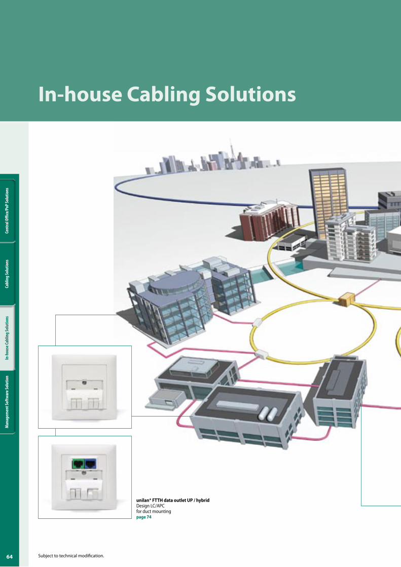
64
Cent
ral O
ffice
/PoP
Solu
tions
Cabl
ing
Solu
tions
In-h
ouse
Cabl
ing
Solu
tions
Man
agem
ent S
oftw
are S
olut
ion
Subject to technical modification.
In-house Cabling Solutions
unilan® FTTH data outlet UP / hybridDesign LC/APC for duct mountingpage �4
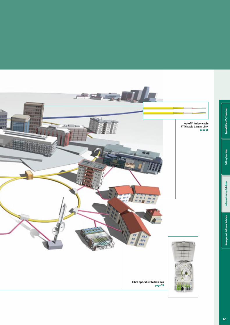
6�
Cent
ral O
ffice
/PoP
Solu
tions
Cabl
ing
Solu
tions
In-h
ouse
Cabl
ing
Solu
tions
Man
agem
ent S
oftw
are S
olut
ion
Fibre optic distribution boxpage �0
optofil® indoor cableFTTH cable 2.2 mm, LS0H
page 66
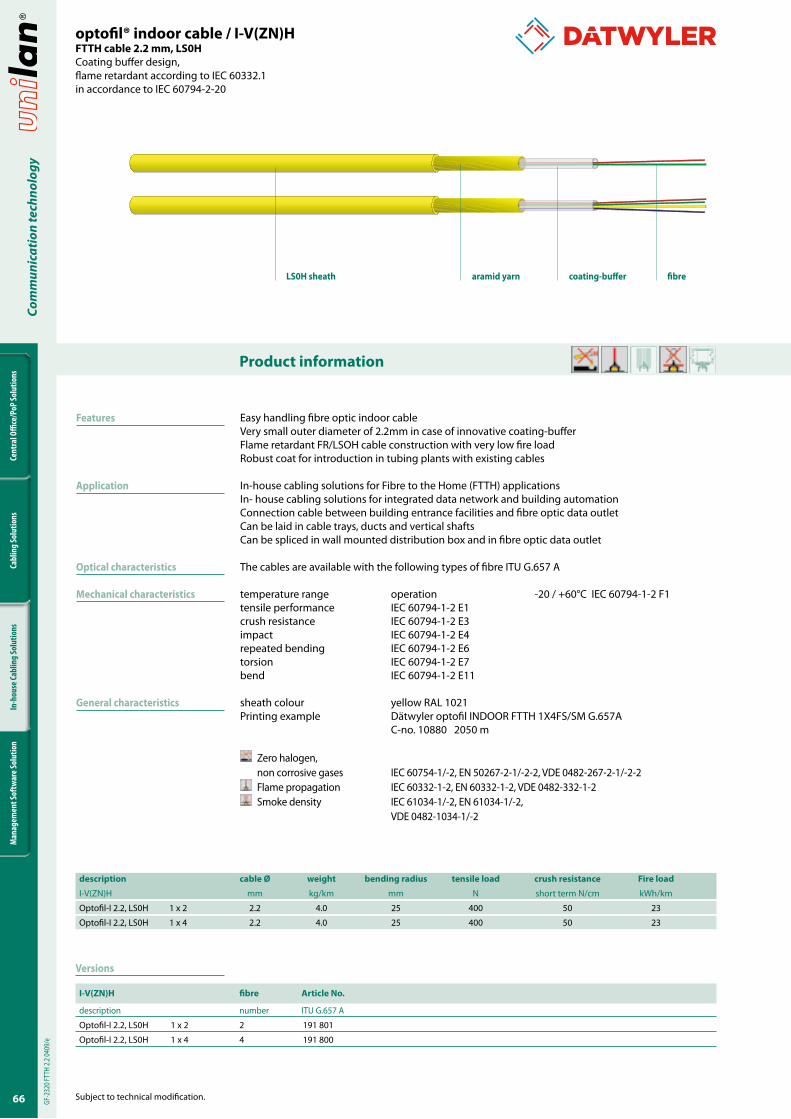
66
Cent
ral O
ffice
/PoP
Solu
tions
Cabl
ing
Solu
tions
In-h
ouse
Cabl
ing
Solu
tions
Man
agem
ent S
oftw
are S
olut
ion
Com
mun
icat
ion
tech
nolo
gy
Product information
Subject to technical modification.
Easy handling fibre optic indoor cableVery small outer diameter of 2.2mm in case of innovative coating-bufferFlame retardant FR/LSOH cable construction with very low fire loadRobust coat for introduction in tubing plants with existing cables
In-house cabling solutions for Fibre to the Home (FTTH) applicationsIn- house cabling solutions for integrated data network and building automationConnection cable between building entrance facilities and fibre optic data outletCan be laid in cable trays, ducts and vertical shaftsCan be spliced in wall mounted distribution box and in fibre optic data outlet
The cables are available with the following types of fibre ITU G.657 A
temperature range operation -20 / +60°C IEC 60794-1-2 F1tensile performance IEC 60794-1-2 E1crush resistance IEC 60794-1-2 E3impact IEC 60794-1-2 E4repeated bending IEC 60794-1-2 E6torsion IEC 60794-1-2 E7bend IEC 60794-1-2 E11
sheath colour yellow RAL 1021Printing example Dätwyler optofil INDOOR FTTH 1X4FS/SM G.657A C-no. 10880 2050 m
Zero halogen, non corrosive gases IEC 60754-1/-2, EN 50267-2-1/-2-2, VDE 0482-267-2-1/-2-2
Flame propagation IEC 60332-1-2, EN 60332-1-2, VDE 0482-332-1-2 Smoke density IEC 61034-1/-2, EN 61034-1/-2,
VDE 0482-1034-1/-2
optofil® indoor cable / I-V(ZN)HFTTH cable 2.2 mm, LS0HCoating buffer design, flame retardant according to IEC 60332.1in accordance to IEC 60794-2-20
LS0H sheath aramid yarn coating-buffer fibre
GF-2
320 F
TTH
2.2 04
09/e
Features
Application
Optical characteristics
Mechanical characteristics
General characteristics
Versions
I-V(ZN)H fibre Article No.
description number ITU G.657 A
Optofil-I 2.2, LS0H 1 x 2 2 191 801
Optofil-I 2.2, LS0H 1 x 4 4 191 800
description cable Ø weight bending radius tensile load crush resistance Fire load
I-V(ZN)H mm kg/km mm N short term N/cm kWh/km
Optofil-I 2.2, LS0H 1 x 2 2.2 4.0 25 400 50 23
Optofil-I 2.2, LS0H 1 x 4 2.2 4.0 25 400 50 23
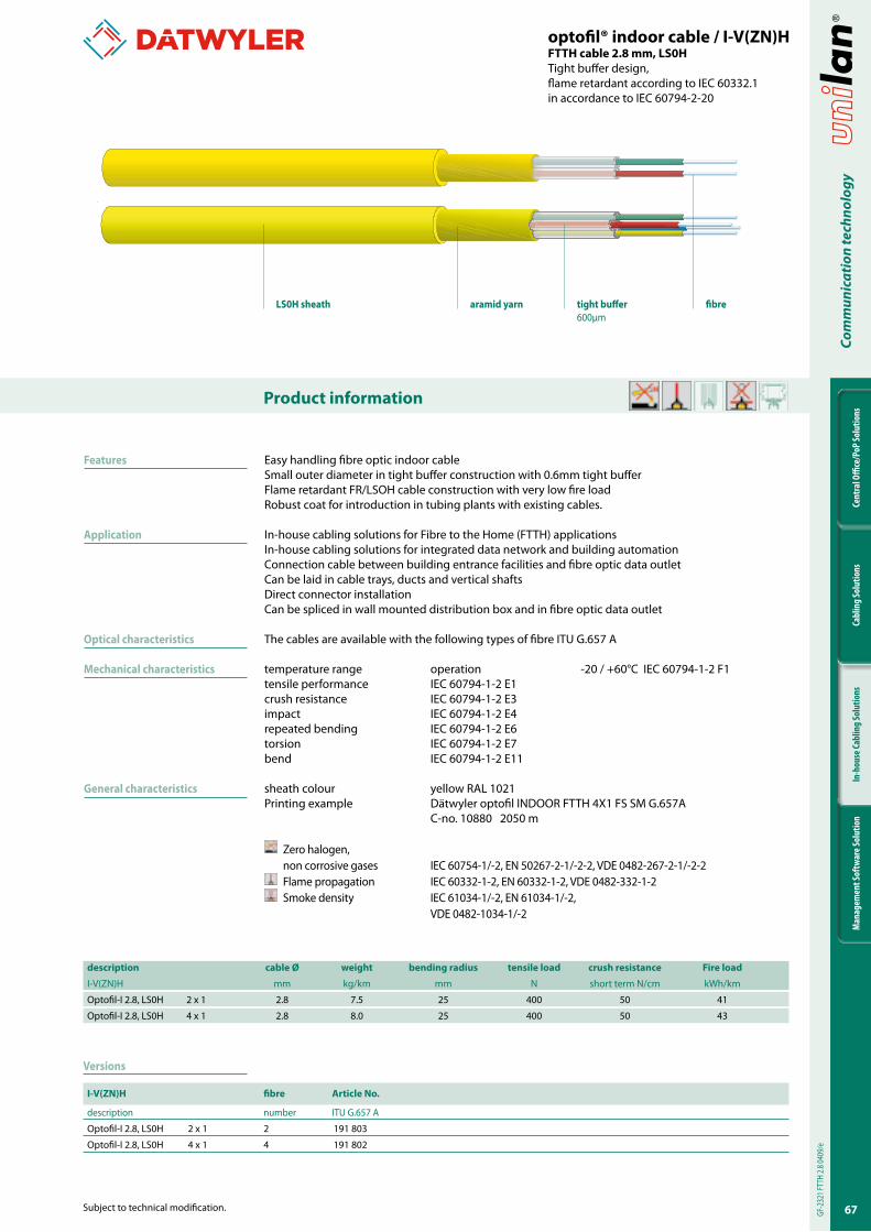
6�
Cent
ral O
ffice
/PoP
Solu
tions
Cabl
ing
Solu
tions
In-h
ouse
Cabl
ing
Solu
tions
Man
agem
ent S
oftw
are S
olut
ion
Com
mun
icat
ion
tech
nolo
gy
Subject to technical modification.
Product information
Easy handling fibre optic indoor cableSmall outer diameter in tight buffer construction with 0.6mm tight bufferFlame retardant FR/LSOH cable construction with very low fire loadRobust coat for introduction in tubing plants with existing cables.
In-house cabling solutions for Fibre to the Home (FTTH) applicationsIn-house cabling solutions for integrated data network and building automationConnection cable between building entrance facilities and fibre optic data outletCan be laid in cable trays, ducts and vertical shaftsDirect connector installationCan be spliced in wall mounted distribution box and in fibre optic data outlet
The cables are available with the following types of fibre ITU G.657 A
temperature range operation -20 / +60°C IEC 60794-1-2 F1tensile performance IEC 60794-1-2 E1crush resistance IEC 60794-1-2 E3impact IEC 60794-1-2 E4repeated bending IEC 60794-1-2 E6torsion IEC 60794-1-2 E7bend IEC 60794-1-2 E11
sheath colour yellow RAL 1021Printing example Dätwyler optofil INDOOR FTTH 4X1 FS SM G.657A C-no. 10880 2050 m
Zero halogen, non corrosive gases IEC 60754-1/-2, EN 50267-2-1/-2-2, VDE 0482-267-2-1/-2-2
Flame propagation IEC 60332-1-2, EN 60332-1-2, VDE 0482-332-1-2 Smoke density IEC 61034-1/-2, EN 61034-1/-2,
VDE 0482-1034-1/-2
optofil® indoor cable / I-V(ZN)HFTTH cable 2.8 mm, LS0HTight buffer design, flame retardant according to IEC 60332.1in accordance to IEC 60794-2-20
GF-2
321 F
TTH
2.8 04
09/e
Features
Application
Optical characteristics
Mechanical characteristics
General characteristics
Versions
I-V(ZN)H fibre Article No.
description number ITU G.657 A
Optofil-I 2.8, LS0H 2 x 1 2 191 803
Optofil-I 2.8, LS0H 4 x 1 4 191 802
description cable Ø weight bending radius tensile load crush resistance Fire load
I-V(ZN)H mm kg/km mm N short term N/cm kWh/km
Optofil-I 2.8, LS0H 2 x 1 2.8 7.5 25 400 50 41
Optofil-I 2.8, LS0H 4 x 1 2.8 8.0 25 400 50 43
LS0H sheath aramid yarn tight buffer600µm
fibre
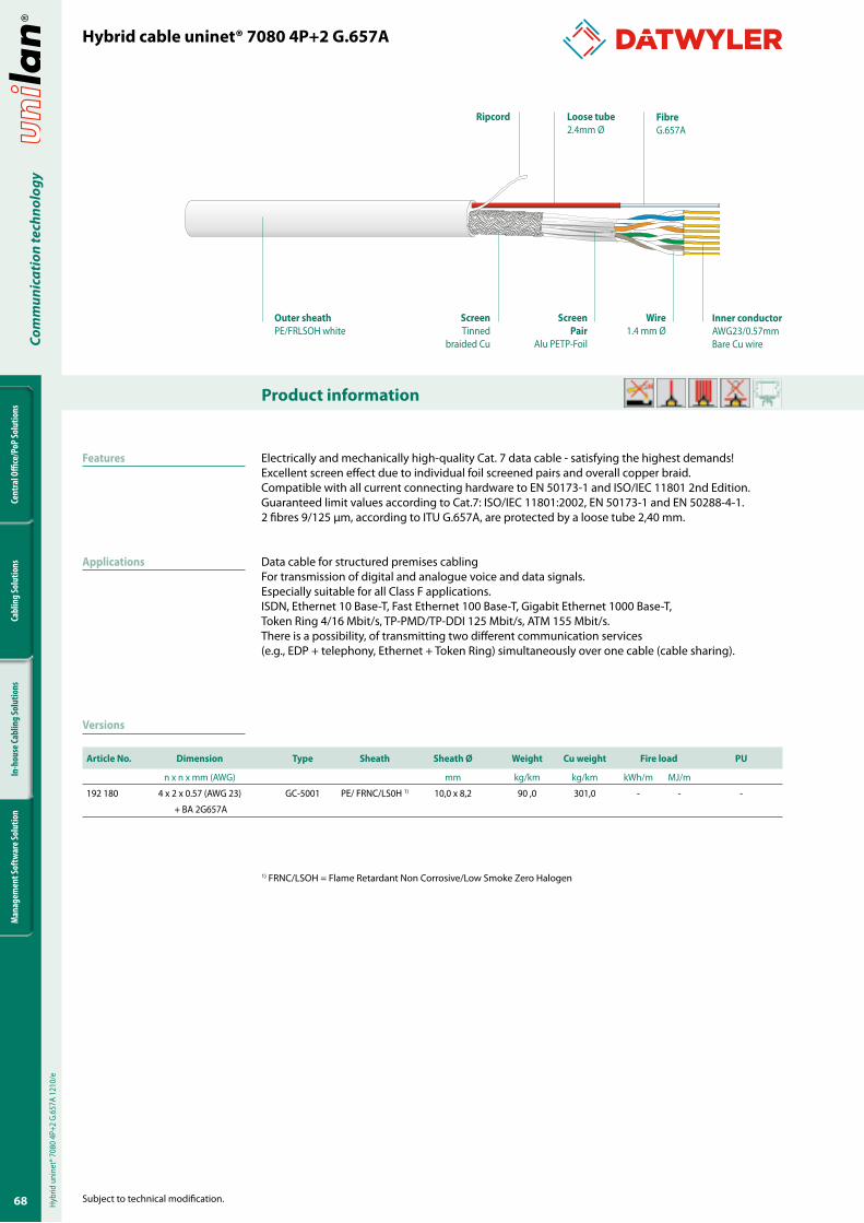
68
Cent
ral O
ffice
/PoP
Solu
tions
Cabl
ing
Solu
tions
In-h
ouse
Cabl
ing
Solu
tions
Man
agem
ent S
oftw
are S
olut
ion
Com
mun
icat
ion
tech
nolo
gy
Product information
Subject to technical modification.
Hybrid cable uninet® �080 4P+2 G.6��A
Features
Applications
Versions
1) FRNC/LSOH = Flame Retardant Non Corrosive/Low Smoke Zero Halogen
Article No. Dimension Type Sheath Sheath Ø Weight Cu weight Fire load PU
n x n x mm (AWG) mm kg/km kg/km kWh/m MJ/m
192 180 4 x 2 x 0.57 (AWG 23) GC-5001 PE/ FRNC/LS0H 1) 10,0 x 8,2 90 ,0 301,0 - - -
+ BA 2G657A
Electrically and mechanically high-quality Cat. 7 data cable - satisfying the highest demands!Excellent screen effect due to individual foil screened pairs and overall copper braid.Compatible with all current connecting hardware to EN 50173-1 and ISO/IEC 11801 2nd Edition.Guaranteed limit values according to Cat.7: ISO/IEC 11801:2002, EN 50173-1 and EN 50288-4-1.2 fibres 9/125 μm, according to ITU G.657A, are protected by a loose tube 2,40 mm.
Data cable for structured premises cablingFor transmission of digital and analogue voice and data signals.Especially suitable for all Class F applications.ISDN, Ethernet 10 Base-T, Fast Ethernet 100 Base-T, Gigabit Ethernet 1000 Base-T, Token Ring 4/16 Mbit/s, TP-PMD/TP-DDI 125 Mbit/s, ATM 155 Mbit/s.There is a possibility, of transmitting two different communication services (e.g., EDP + telephony, Ethernet + Token Ring) simultaneously over one cable (cable sharing).
Hybr
id u
nine
t® 7
080
4P+2
G.6
57A
1210
/e
Outer sheathPE/FRLSOH white
Inner conductorAWG23/0.57mmBare Cu wire
FibreG.657A
Wire1.4 mm Ø
Loose tube2.4mm Ø
ScreenTinned
braided Cu
Ripcord
ScreenPair
Alu PETP-Foil
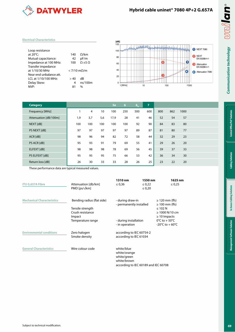
69
Cent
ral O
ffice
/PoP
Solu
tions
Cabl
ing
Solu
tions
In-h
ouse
Cabl
ing
Solu
tions
Man
agem
ent S
oftw
are S
olut
ion
Com
mun
icat
ion
tech
nolo
gy
Subject to technical modification.
ITU G.6��A Fibre
Mechanical Characteristics
Environmental conditions
General Characteristics
Electrical Characteristics
Hybrid cable uninet® �080 4P+2 G.6��A
Loop resistanceat 20°C: 140 Ω/kmMutual capacitance: 42 pF/mImpedance at 100 MHz: 100 Ω ±5 ΩTransfer impedanceat 1/10/30 MHz < 7/10 mΩ/mNear end unbalance att. LCL at 1/10/100 MHz: > 40 dBDelay Skew: 4 ns/100mNVP: 81 %
�3�0 nm ���0 nm �62� nmAttenuation [db/km] ≤ 0,36 ≤ 0,22 ≤ 0,25PMD [ps/√km] ≤ 0,20
Bending radius (flat side) - during draw-in ≥ 120 mm (ffs) - permanently installed ≥ 100 mm (ffs) Tensile strength ≤ 102 N Crush resistance ≥ 1000 N/10 cmImpact ≥ 10 ImpactsTemperature range - during installation 0°C to + 50°C - in operation -20°C to + 60°C
Zero halogen according to IEC 60754-2Smoke density according to IEC 61034
Wire colour code white/blue white/orange white/green white/brown according to IEC 60189 and IEC 60708
NEXT 7080
NEXTEN 50288-4-1
AttenuationEN 50288-4-1
Attenuation 7080
1
2
3
4
0
20
40
60
80
100
120
1 10 100 1'000[MHz]
[dB]
2
3
1
4
Category �e 6 6A �
Frequency [MHz] 1 4 10 100 250 500 600 800 862 1000
Attenuation [dB/100m] 1,9 3,7 5,6 17,9 28 41 46 52 54 57
NEXT [dB] 100 100 100 100 100 92 90 84 83 80
PS NEXT [dB] 97 97 97 97 97 89 87 81 80 77
ACR [dB] 98 96 94 82 72 58 44 32 29 23
PS ACR [dB] 95 93 91 79 69 55 41 29 26 20
ELFEXT [dB] 98 98 98 78 69 56 45 39 37 33
PS ELFEXT [dB] 95 95 95 75 66 53 42 36 34 30
Return loss [dB] 26 30 33 33 28 26 25 23 22 20
These performance data are typical measured values.
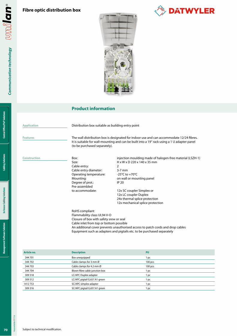
�0
Cent
ral O
ffice
/PoP
Solu
tions
Cabl
ing
Solu
tions
In-h
ouse
Cabl
ing
Solu
tions
Man
agem
ent S
oftw
are S
olut
ion
Com
mun
icat
ion
tech
nolo
gy
Product information
Subject to technical modification.
Article no. Description PU
344 701 Box unequipped 1 pc
344 702 Cable clamps for 3 mm Ø 100 pcs
344 703 Cable clamps for 4.2 mm Ø 100 pcs
344 704 Blown fibre cable junction box 1 pc
309 318 LC/APC Duplex adapter 1 pc
309 312 LC/APC pigtail G.657.A1 green 1 pc
1412 753 SC/APC simplex adapter 1 pc
309 316 SC/APC pigtail G.657.A1 green 1 pc
Application
Features
Construction
Distribution box suitable as building entry point
The wall distribution box is designated for indoor use and can accommodate 12/24 fibres. It is suitable for wall-mounting and can be built into a 19“ rack using a 1 U adapter panel (to be purchased separately).
Box: injection moulding made of halogen-free material (LSZH-1)Size: H x W x D 220 x 140 x 35 mmCable entry: 2Cable entry diameter: 3-7 mmOperating temperature: -25°C to +70°CMounting: on wall or mounting panel Degree of prot.: IP 20Pre-assembled to accommodate: 12x SC coupler Simplex or 12x LC coupler Duplex 24x thermal splice protection 12x mechanical splice protection
RoHS compliantFlammability class UL94 V-OClosure of box with safety srew or sealCable inlet from top or bottom possibleAn additional cover prevents unauthorised access to patch cords and drop cablesEquipment such as adapters and pigtails etc. to be purchased separately
Fibre optic distribution boxHa
usve
rteile
r 011
1/e
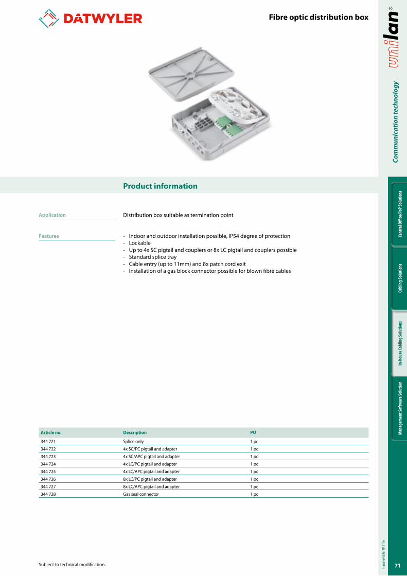
��
Cent
ral O
ffice
/PoP
Solu
tions
Cabl
ing
Solu
tions
In-h
ouse
Cabl
ing
Solu
tions
Man
agem
ent S
oftw
are S
olut
ion
Com
mun
icat
ion
tech
nolo
gy
Subject to technical modification.
Product information
Article no. Description PU
344 721 Splice only 1 pc
344 722 4x SC/PC pigtail and adapter 1 pc
344 723 4x SC/APC pigtail and adapter 1 pc
344 724 4x LC/PC pigtail and adapter 1 pc
344 725 4x LC/APC pigtail and adapter 1 pc
344 726 8x LC/PC pigtail and adapter 1 pc
344 727 8x LC/APC pigtail and adapter 1 pc
344 728 Gas seal connector 1 pc
Application
Features
Distribution box suitable as termination point
- Indoor and outdoor installation possible, IP54 degree of protection- Lockable- Up to 4x SC pigtail and couplers or 8x LC pigtail and couplers possible- Standard splice tray- Cable entry (up to 11mm) and 8x patch cord exit- Installation of a gas block connector possible for blown fibre cables
Fibre optic distribution box
Haus
verte
iler 0
111/
e
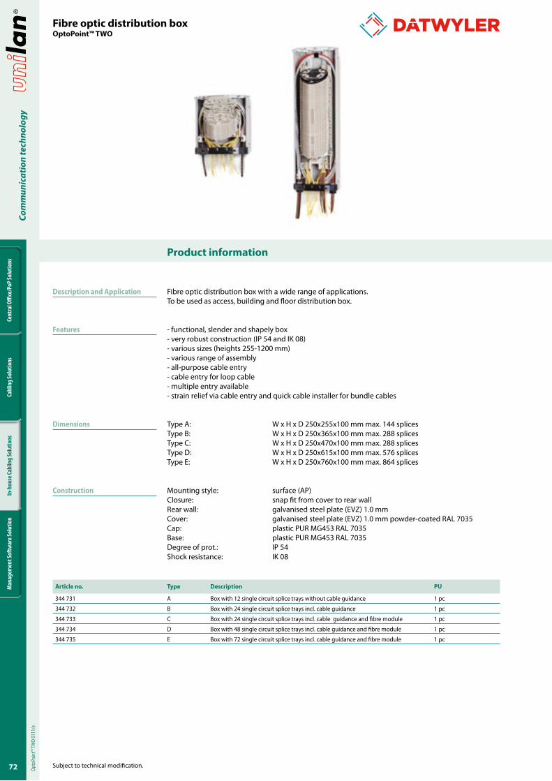
�2
Cent
ral O
ffice
/PoP
Solu
tions
Cabl
ing
Solu
tions
In-h
ouse
Cabl
ing
Solu
tions
Man
agem
ent S
oftw
are S
olut
ion
Com
mun
icat
ion
tech
nolo
gy
Product information
Subject to technical modification.
Article no. Type Description PU
344 731 A Box with 12 single circuit splice trays without cable guidance 1 pc
344 732 B Box with 24 single circuit splice trays incl. cable guidance 1 pc
344 733 C Box with 24 single circuit splice trays incl. cable guidance and fibre module 1 pc
344 734 D Box with 48 single circuit splice trays incl. cable guidance and fibre module 1 pc
344 735 E Box with 72 single circuit splice trays incl. cable guidance and fibre module 1 pc
Description and Application
Features
Dimensions
Construction
Fibre optic distribution box with a wide range of applications. To be used as access, building and floor distribution box.
- functional, slender and shapely box- very robust construction (IP 54 and IK 08)- various sizes (heights 255-1200 mm)- various range of assembly- all-purpose cable entry- cable entry for loop cable- multiple entry available- strain relief via cable entry and quick cable installer for bundle cables
Type A: W x H x D 250x255x100 mm max. 144 splicesType B: W x H x D 250x365x100 mm max. 288 splicesType C: W x H x D 250x470x100 mm max. 288 splicesType D: W x H x D 250x615x100 mm max. 576 splicesType E: W x H x D 250x760x100 mm max. 864 splices
Mounting style: surface (AP)Closure: snap fit from cover to rear wallRear wall: galvanised steel plate (EVZ) 1.0 mmCover: galvanised steel plate (EVZ) 1.0 mm powder-coated RAL 7035Cap: plastic PUR MG453 RAL 7035Base: plastic PUR MG453 RAL 7035Degree of prot.: IP 54Shock resistance: IK 08
Fibre optic distribution boxOptoPoint™ TWO
Opto
Poin
t™ TW
O 01
11/e
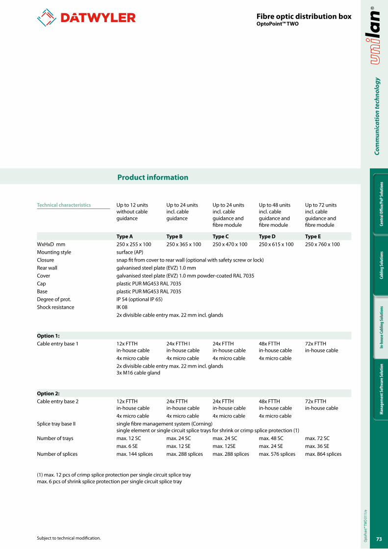
�3
Cent
ral O
ffice
/PoP
Solu
tions
Cabl
ing
Solu
tions
In-h
ouse
Cabl
ing
Solu
tions
Man
agem
ent S
oftw
are S
olut
ion
Com
mun
icat
ion
tech
nolo
gy
Subject to technical modification.
Product information
Up to 12 units without cable guidance
Up to 24 units incl. cable guidance
Up to 24 units incl. cable guidance and fibre module
Up to 48 units incl. cable guidance and fibre module
Up to 72 units incl. cable guidance and fibre module
Type A Type B Type C Type D Type EWxHxD mm 250 x 255 x 100 250 x 365 x 100 250 x 470 x 100 250 x 615 x 100 250 x 760 x 100 Mounting style surface (AP)Closure snap fit from cover to rear wall (optional with safety screw or lock)Rear wall galvanised steel plate (EVZ) 1.0 mmCover galvanised steel plate (EVZ) 1.0 mm powder-coated RAL 7035Cap plastic PUR MG453 RAL 7035Base plastic PUR MG453 RAL 7035Degree of prot. IP 54 (optional IP 65)Shock resistance IK 08
2x divisible cable entry max. 22 mm incl. glands
Option �:Cable entry base 1 12x FTTH
in-house cable24x FTTH Iin-house cable
24x FTTH in-house cable
48x FTTH in-house cable
72x FTTH in-house cable
4x micro cable 4x micro cable 4x micro cable 4x micro cable2x divisible cable entry max. 22 mm incl. glands3x M16 cable gland
Option 2:Cable entry base 2 12x FTTH
in-house cable24x FTTH in-house cable
24x FTTH in-house cable
48x FTTH in-house cable
72x FTTH in-house cable
4x micro cable 4x micro cable 4x micro cable 4x micro cableSplice tray base II single fibre management system (Corning)
single element or single circuit splice trays for shrink or crimp splice protection (1)Number of trays max. 12 SC max. 24 SC max. 24 SC max. 48 SC max. 72 SC
max. 6 SE max. 12 SE max. 12SE max. 24 SE max. 36 SENumber of splices max. 144 splices max. 288 splices max. 288 splices max. 576 splices max. 864 splices
(1) max. 12 pcs of crimp splice protection per single circuit splice traymax. 6 pcs of shrink splice protection per single circuit splice tray
Opto
Poin
t™ TW
O 01
11/e
Fibre optic distribution boxOptoPoint™ TWO
Technical characteristics
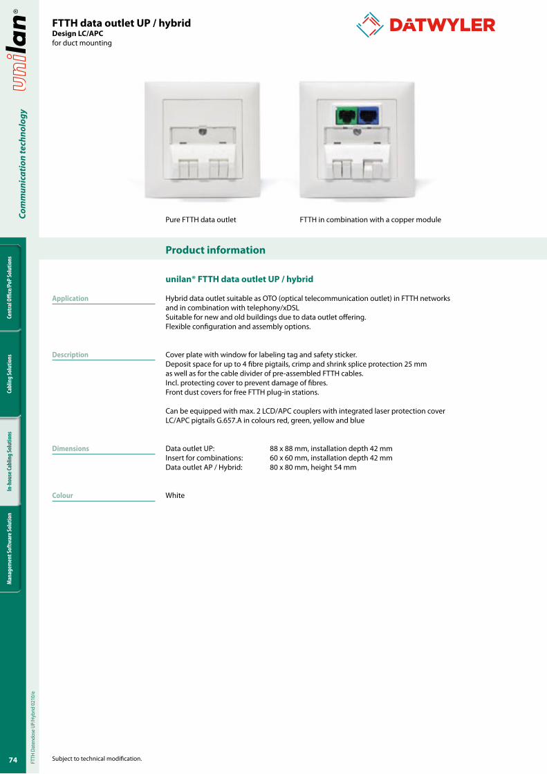
�4
Cent
ral O
ffice
/PoP
Solu
tions
Cabl
ing
Solu
tions
In-h
ouse
Cabl
ing
Solu
tions
Man
agem
ent S
oftw
are S
olut
ion
Com
mun
icat
ion
tech
nolo
gy
Product information
Subject to technical modification.
FTTH data outlet UP / hybridDesign LC/APC for duct mounting
Application
Description
Dimensions
Colour
Pure FTTH data outlet FTTH in combination with a copper module
unilan® FTTH data outlet UP / hybrid
Hybrid data outlet suitable as OTO (optical telecommunication outlet) in FTTH networks and in combination with telephony/xDSLSuitable for new and old buildings due to data outlet offering.Flexible configuration and assembly options.
Cover plate with window for labeling tag and safety sticker. Deposit space for up to 4 fibre pigtails, crimp and shrink splice protection 25 mm as well as for the cable divider of pre-assembled FTTH cables.Incl. protecting cover to prevent damage of fibres.Front dust covers for free FTTH plug-in stations.
Can be equipped with max. 2 LCD/APC couplers with integrated laser protection coverLC/APC pigtails G.657.A in colours red, green, yellow and blue
Data outlet UP: 88 x 88 mm, installation depth 42 mmInsert for combinations: 60 x 60 mm, installation depth 42 mmData outlet AP / Hybrid: 80 x 80 mm, height 54 mm
White
FTTH
Dat
endo
se U
P/Hy
brid
021
0/e
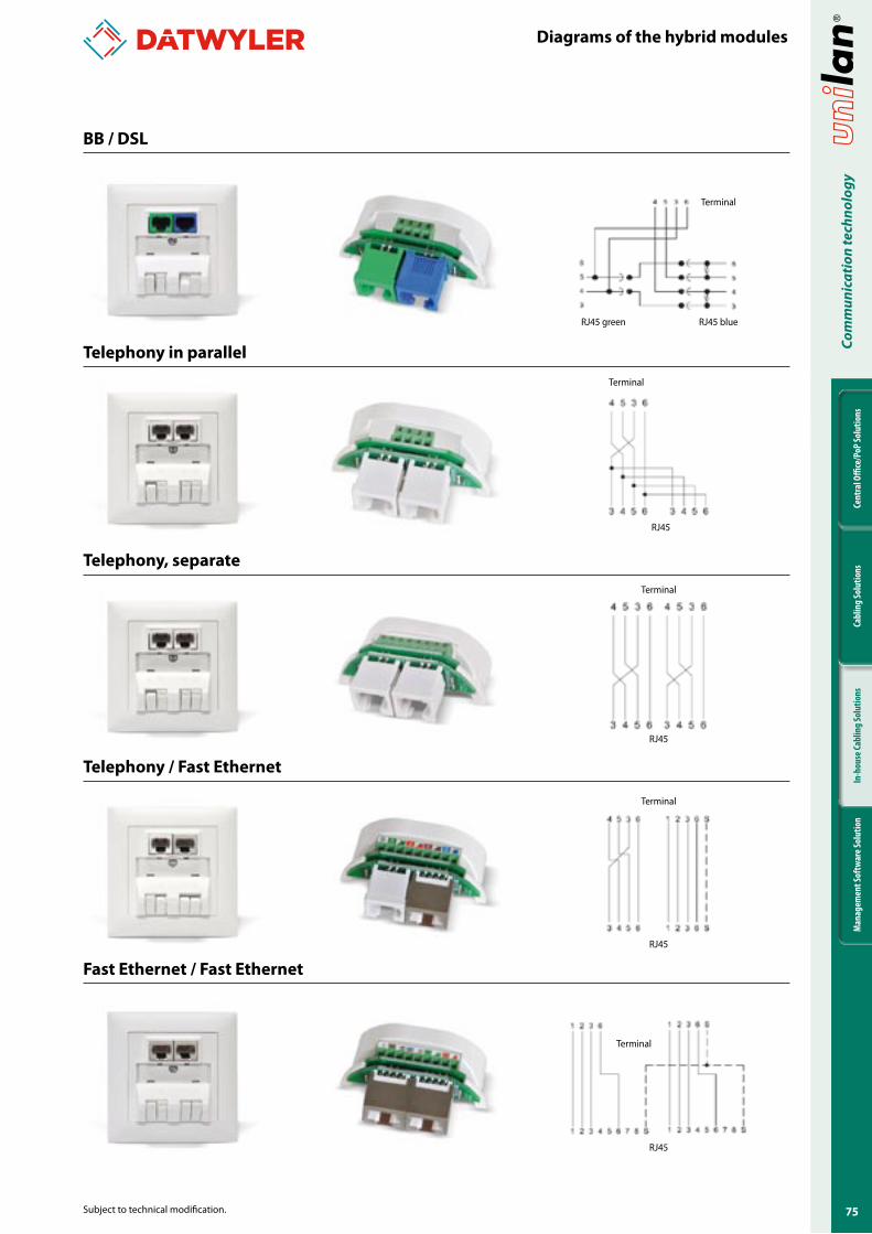
��
Cent
ral O
ffice
/PoP
Solu
tions
Cabl
ing
Solu
tions
In-h
ouse
Cabl
ing
Solu
tions
Man
agem
ent S
oftw
are S
olut
ion
Com
mun
icat
ion
tech
nolo
gy
Subject to technical modification.
Diagrams of the hybrid modules
BB / DSL
Telephony in parallel
Telephony, separate
Telephony / Fast Ethernet
Fast Ethernet / Fast Ethernet
Terminal
RJ45 blueRJ45 green
Terminal
RJ45
Terminal
RJ45
Terminal
RJ45
Terminal
RJ45
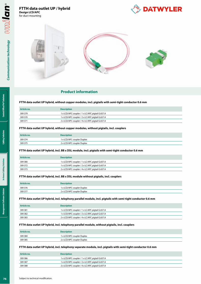
�6
Cent
ral O
ffice
/PoP
Solu
tions
Cabl
ing
Solu
tions
In-h
ouse
Cabl
ing
Solu
tions
Man
agem
ent S
oftw
are S
olut
ion
Com
mun
icat
ion
tech
nolo
gy
Product information
Subject to technical modification.
FTTH data outlet UP hybrid, without copper modules, incl. pigtails with semi-tight conductor 0.6 mm
Article no. Description
309 379 1 x LCD/APC coupler / 1 x LC/APC pigtail G.657.A
309 370 1 x LCD/APC coupler / 2 x LC/APC pigtail G.657.A
309 371 2 x LCD/APC coupler / 4 x LC/APC pigtail G.657.A
FTTH data outlet UP hybrid, without copper modules, without pigtails, incl. couplers
Article no. Description
309 374 1 x LCD/APC coupler Duplex
309 375 2 x LCD/APC coupler Duplex
FTTH data outlet UP hybrid, incl. BB x DSL module, incl. pigtails with semi-tight conductor 0.6 mm
Article no. Description
309 380 1 x LCD/APC coupler / 1 x LC/APC pigtail G.657.A
309 372 1 x LCD/APC coupler / 2 x LC/APC pigtail G.657.A
309 373 2 x LCD/APC coupler / 4 x LC/APC pigtail G.657.A
FTTH data outlet UP hybrid, incl. BB x DSL module without pigtails, incl. couplers
Article no. Description
309 376 1 x LCD/APC coupler Duplex
309 377 2 x LCD/APC coupler Duplex
FTTH data outlet UP hybrid, incl. telephony parallel module, incl. pigtails with semi-tight conductor 0.6 mm
Article no. Description
309 381 1 x LCD/APC coupler / 1 x LC/APC pigtail G.657.A
309 382 1 x LCD/APC coupler / 2 x LC/APC pigtail G.657.A
309 383 2 x LCD/APC coupler / 4 x LC/APC pigtail G.657.A
FTTH data outlet UP hybrid, incl. telephony parallel module, without pigtails, incl. couplers
Article no. Description
309 384 1 x LCD/APC coupler Duplex
309 385 2 x LCD/APC coupler Duplex
FTTH data outlet UP hybrid, incl. telephony separate module, incl. pigtails with semi-tight conductor 0.6 mm
Article no. Description
309 386 1 x LCD/APC coupler / 1 x LC/APC pigtail G.657.A
309 387 1 x LCD/APC coupler / 2 x LC/APC pigtail G.657.A
309 388 2 x LCD/APC coupler / 4 x LC/APC pigtail G.657.A
FTTH data outlet UP / hybridDesign LCD/APC for duct mounting
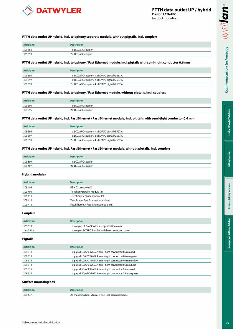
��
Cent
ral O
ffice
/PoP
Solu
tions
Cabl
ing
Solu
tions
In-h
ouse
Cabl
ing
Solu
tions
Man
agem
ent S
oftw
are S
olut
ion
Com
mun
icat
ion
tech
nolo
gy
Subject to technical modification.
FTTH data outlet UP / hybridDesign LCD/APC for duct mounting
FTTH data outlet UP hybrid, incl. telephony separate module, without pigtails, incl. couplers
Article no. Description
309 389 1 x LCD/APC coupler
309 390 2 x LCD/APC coupler
FTTH data outlet UP hybrid, incl. telephony / Fast Ethernet module, incl. pigtails with semi-tight conductor 0.6 mm
Article no. Description
309 391 1 x LCD/APC coupler / 1 x LC/APC pigtail G.657.A
309 392 1 x LCD/APC coupler / 2 x LC/APC pigtail G.657.A
309 393 2 x LCD/APC coupler / 4 x LC/APC pigtail G.657.A
FTTH data outlet UP hybrid, incl. telephony / Fast Ethernet module, without pigtails, incl. couplers
Article no. Description
309 394 1 x LCD/APC coupler
309 395 2 x LCD/APC coupler
FTTH data outlet UP hybrid, incl. Fast Ethernet / Fast Ethernet module, incl. pigtails with semi-tight conductor 0.6 mm
Article no. Description
309 396 1 x LCD/APC coupler / 1 x LC/APC pigtail G.657.A
309 397 1 x LCD/APC coupler / 2 x LC/APC pigtail G.657.A
309 398 2 x LCD/APC coupler / 4 x LC/APC pigtail G.657.A
FTTH data outlet UP hybrid, incl. Fast Ethernet / Fast Ethernet module, without pigtails, incl. couplers
Article no. Description
309 399 1 x LCD/APC coupler
309 407 2 x LCD/APC coupler
Hybrid modules
Article no. Description
309 408 BB x DSL module (1)
309 409 Telephony parallel module (2)
309 411 Telephony separate module (3)
309 412 Telephony / Fast Ethernet module (4)
309 413 Fast Ethernet / Fast Ethernet module (5)
Couplers
Article no. Description
309 318 1 x coupler LCD/APC with laser protection cover
1 412 753 1 x coupler SC/APC Simplex with laser protection cover
Pigtails
Article no. Description
309 311 1 x pigtail LC/APC G.657.A semi-tight conductor 0.6 mm red
309 312 1 x pigtail LC/APC G.657.A semi-tight conductor 0.6 mm green
309 313 1 x pigtail LC/APC G.657.A semi-tight conductor 0.6 mm yellow
309 314 1 x pigtail LC/APC G.657.A semi-tight conductor 0.6 mm blue
309 315 1 x pigtail SC/APC G.657.A semi-tight conductor 0.6 mm red
309 316 1 x pigtail SC/APC G.657.A semi-tight conductor 0.6 mm green
Surface mounting box
Article no. Description
309 447 AP mounting box, 54mm, white, incl. assembly frame
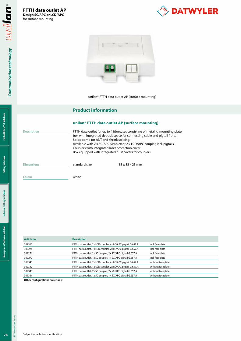
�8
Cent
ral O
ffice
/PoP
Solu
tions
Cabl
ing
Solu
tions
In-h
ouse
Cabl
ing
Solu
tions
Man
agem
ent S
oftw
are S
olut
ion
Com
mun
icat
ion
tech
nolo
gy
Product information
Subject to technical modification.
FTTH data outlet APDesign SC/APC or LCD/APCfor surface mounting
unilan® FTTH data outlet AP (surface mounting)
Description
Dimensions
Colour
unilan® FTTH data outlet AP (surface mounting)
FTTH data outlet for up to 4 fibres, set consisting of metallic mounting plate, box with integrated deposit space for connecting cable and pigtail fibre.Splice comb for ANT and shrink splicing.Available with 2 x SC/APC Simplex or 2 x LCD/APC coupler, incl. pigtails.Couplers with integrated laser protection cover.Box equipped with integrated dust covers for couplers.
standard size: 88 x 88 x 23 mm
white
Article no. Description
309317 FTTH data outlet, 2x LCD coupler, 4x LC/APC pigtail G.657.A incl. faceplate
309278 FTTH data outlet, 1x LCD coupler, 2x LC/APC pigtail G.657.A incl. faceplate
309276 FTTH data outlet, 2x SC coupler, 2x SC/APC pigtail G.657.A incl. faceplate
309277 FTTH data outlet, 1x SC coupler, 1x SC/APC pigtail G.657.A incl. faceplate
309341 FTTH data outlet, 2x LCD coupler, 4x LC/APC pigtail G.657.A without faceplate
309342 FTTH data outlet, 1x LCD coupler, 2x LC/APC pigtail G.657.A without faceplate
309343 FTTH data outlet, 2x SC coupler, 2x SC/APC pigtail G.657.A without faceplate
309344 FTTH data outlet, 1x SC coupler, 1x SC/APC pigtail G.657.A without faceplate
Other configurations on request.
FTTH
Dat
endo
se 0
111/
e
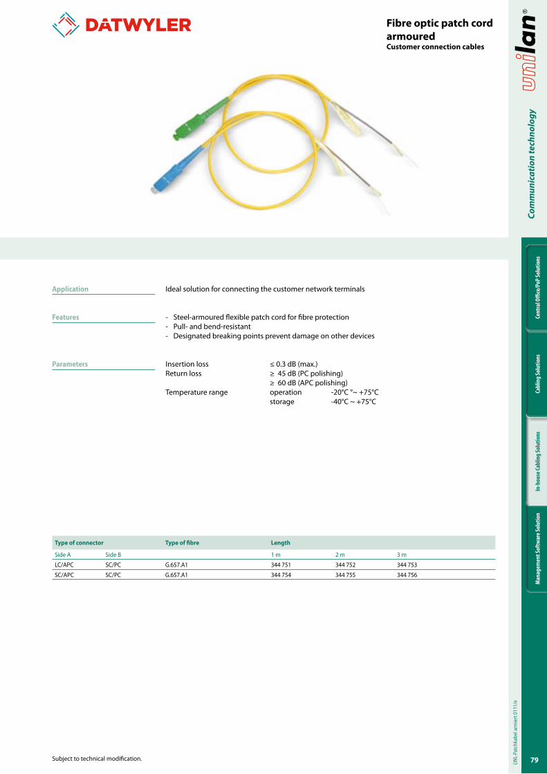
�9
Cent
ral O
ffice
/PoP
Solu
tions
Cabl
ing
Solu
tions
In-h
ouse
Cabl
ing
Solu
tions
Man
agem
ent S
oftw
are S
olut
ion
Com
mun
icat
ion
tech
nolo
gy
Subject to technical modification.
Fibre optic patch cord armouredCustomer connection cables
Type of connector Type of fibre Length
Side A Side B 1 m 2 m 3 m
LC/APC SC/PC G.657.A1 344 751 344 752 344 753
SC/APC SC/PC G.657.A1 344 754 344 755 344 756
Application
Features
Parameters
Ideal solution for connecting the customer network terminals
- Steel-armoured flexible patch cord for fibre protection- Pull- and bend-resistant- Designated breaking points prevent damage on other devices
Insertion loss ≤ 0.3 dB (max.)Return loss ≥ 45 dB (PC polishing) ≥ 60 dB (APC polishing)Temperature range operation -20°C °~ +75°C storage -40°C ~ +75°C
LWL-
Patc
hkab
el a
rmie
rt 0
111/
e
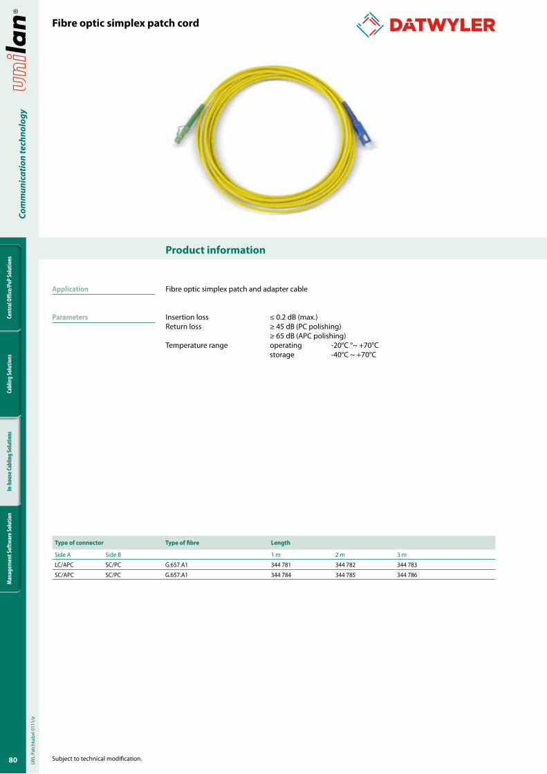
80
Cent
ral O
ffice
/PoP
Solu
tions
Cabl
ing
Solu
tions
In-h
ouse
Cabl
ing
Solu
tions
Man
agem
ent S
oftw
are S
olut
ion
Com
mun
icat
ion
tech
nolo
gy
Product information
Subject to technical modification.
Fibre optic simplex patch cord
Type of connector Type of fibre Length
Side A Side B 1 m 2 m 3 m
LC/APC SC/PC G.657.A1 344 781 344 782 344 783
SC/APC SC/PC G.657.A1 344 784 344 785 344 786
Fibre optic simplex patch and adapter cable
Insertion loss ≤ 0.2 dB (max.)Return loss ≥ 45 dB (PC polishing) ≥ 65 dB (APC polishing)Temperature range operating -20°C °~ +70°C storage -40°C ~ +70°C
LWL-
Patc
hkab
el 0
111/
e
Application
Parameters
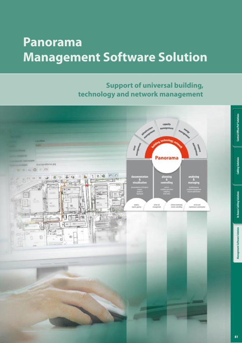
8�
Cent
ral O
ffice
/PoP
Solu
tions
Cabl
ing
Solu
tions
In-h
ouse
Cabl
ing
Solu
tions
Man
agem
ent S
oftw
are S
olut
ion
optofil® Produktübersicht
Support of universal building, technology and network management
PanoramaManagement Software Solution
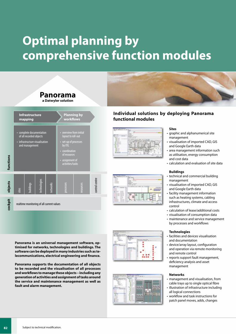
82
Cent
ral O
ffice
/PoP
Solu
tions
Cabl
ing
Solu
tions
In-h
ouse
Cabl
ing
Solu
tions
Man
agem
ent S
oftw
are S
olut
ion
Subject to technical modification.
Optimal planning by comprehensive function modules
Panorama is an universal management software, op-timised for networks, technologies and buildings. The software can be deployed in many industries such as te-lecommunications, electrical engineering and finance.
Panorama supports the documentation of all objects to be recorded and the visualisation of all processes and workflows to manage these objects – including any generation of activities and assignment of tasks around the service and maintenance management as well as fault and alarm management.
Sites• graphic and alphanumerical site
management• visualisation of imported CAD, GIS
and Google Earth data• area management information such
as utilisation, energy consumption and cost data
• calculation and evaluation of site data
Buildings• technical and commercial building
management• visualisation of imported CAD, GIS
and Google Earth data • facility management information
such as heating systems, cabling infrastructures, climate and access control
• calculation of lease/additional costs• visualisation of consumption data• maintenance and service management
by processes and workflows
Technologies• facilities and devices visualisation
and documentation • device/array layout, configuration
and operation via remote monitoring and remote control
• reports support fault management, deficiency analysis and asset management
Networks• management and visualisation, from
cable trays up to single optical fibre• illustration of infrastructure including
all logical connections• workflow and task instructions for
patch panel moves, adds, changes
Panoramaa Datwyler solution
Planning by workflows
• overviewfrominitiallayouttoroll-out
• set-upofprocessesbyITIL
• coordinationofresources
• assignmentofactivities/tasks
proc
esse
s
reso
urce
s
cont
rolc
entre
realtimemonitoringofallcurrentvalues
func
tion
sob
ject
sco
ckpi
t
Individual solutions by deploying Panorama functional modules
• completedocumentationofallrecordedobjects
• infrastructurevisualisationandmanagement
sites
build
ings
tech
nolog
ies
netw
orks
Infrastructure mapping
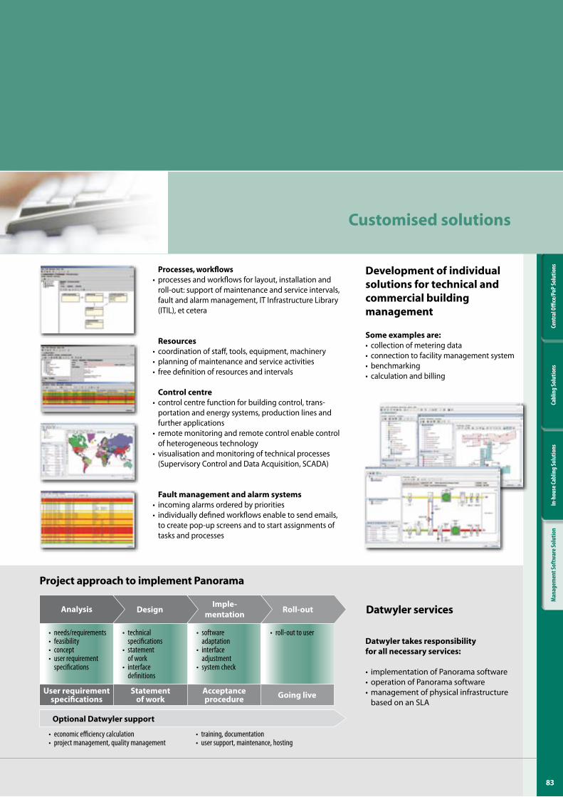
83
Cent
ral O
ffice
/PoP
Solu
tions
Cabl
ing
Solu
tions
In-h
ouse
Cabl
ing
Solu
tions
Man
agem
ent S
oftw
are S
olut
ion
Processes, workflows• processes and workflows for layout, installation and
roll-out: support of maintenance and service intervals, fault and alarm management, IT Infrastructure Library (ITIL), et cetera
Resources• coordination of staff, tools, equipment, machinery• planning of maintenance and service activities• free definition of resources and intervals
Control centre• control centre function for building control, trans-
portation and energy systems, production lines and further applications
• remote monitoring and remote control enable control of heterogeneous technology
• visualisation and monitoring of technical processes (Supervisory Control and Data Acquisition, SCADA)
Fault management and alarm systems• incoming alarms ordered by priorities• individually defined workflows enable to send emails,
to create pop-up screens and to start assignments of tasks and processes
Datwyler services
Datwyler takes responsibility for all necessary services:
• implementation of Panorama software • operation of Panorama software• management of physical infrastructure
based on an SLA
Customised solutions
• needs/requirements• feasibility• concept• userrequirement
specifications
• technicalspecifications
• statementofwork
• interfacedefinitions
• softwareadaptation
• interfaceadjustment
• systemcheck
• roll-outtouser
Roll-outImple-
mentationDesignAnalysis
Going liveAcceptance procedure
Statement of work
User requirement specifications
• economicefficiencycalculation• projectmanagement,qualitymanagement
• training,documentation• usersupport,maintenance,hosting
Optional Datwyler support
Project approach to implement Panorama
Development of individual solutions for technical and commercial building management
Some examples are:• collection of metering data • connection to facility management system• benchmarking• calculation and billing
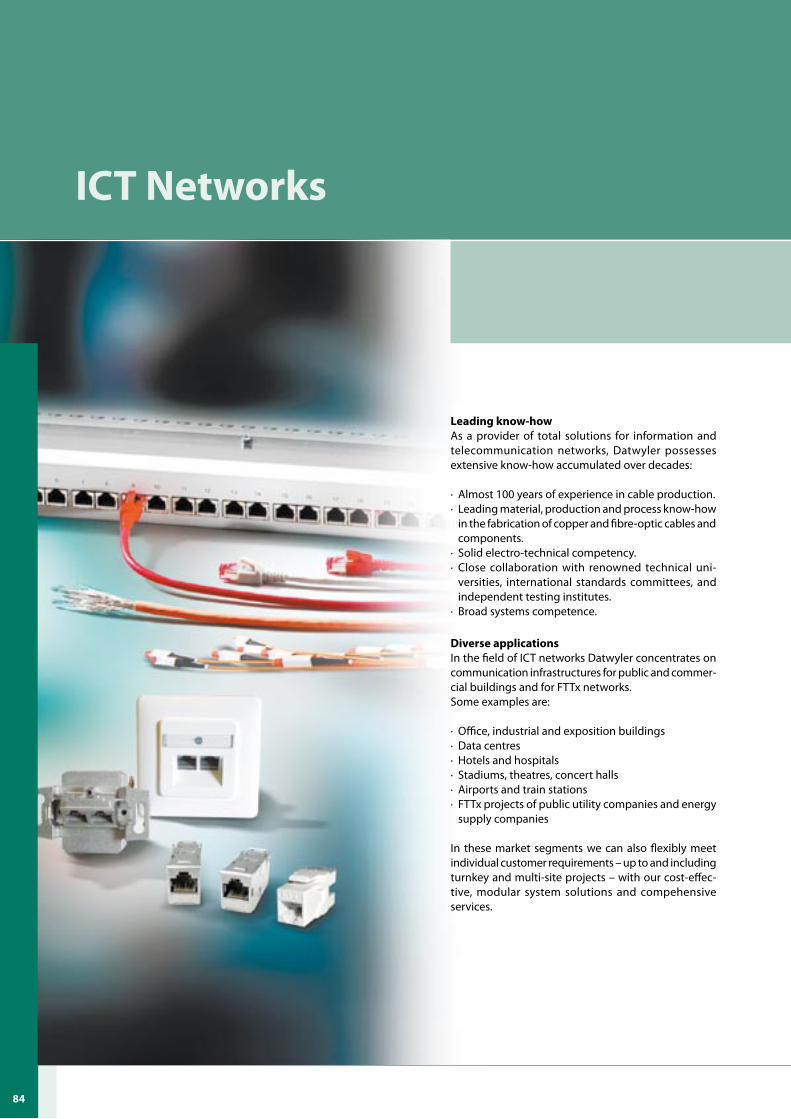
U-84
ICT Networks
Leading know-howAs a provider of total solutions for information and telecommunication networks, Datwyler possesses extensive know-how accumulated over decades:
· Almost 100 years of experience in cable production.· Leading material, production and process know-how
in the fabrication of copper and fibre-optic cables and components.
· Solid electro-technical competency.· Close collaboration with renowned technical uni-
versities, international standards committees, and independent testing institutes.
· Broad systems competence.
Diverse applicationsIn the field of ICT networks Datwyler concentrates on communication infrastructures for public and commer-cial buildings and for FTTx networks.Some examples are:
· Office, industrial and exposition buildings· Data centres· Hotels and hospitals· Stadiums, theatres, concert halls· Airports and train stations · FTTx projects of public utility companies and energy
supply companies
In these market segments we can also flexibly meet individual customer requirements – up to and including turnkey and multi-site projects – with our cost-effec-tive, modular system solutions and compehensive services.
84
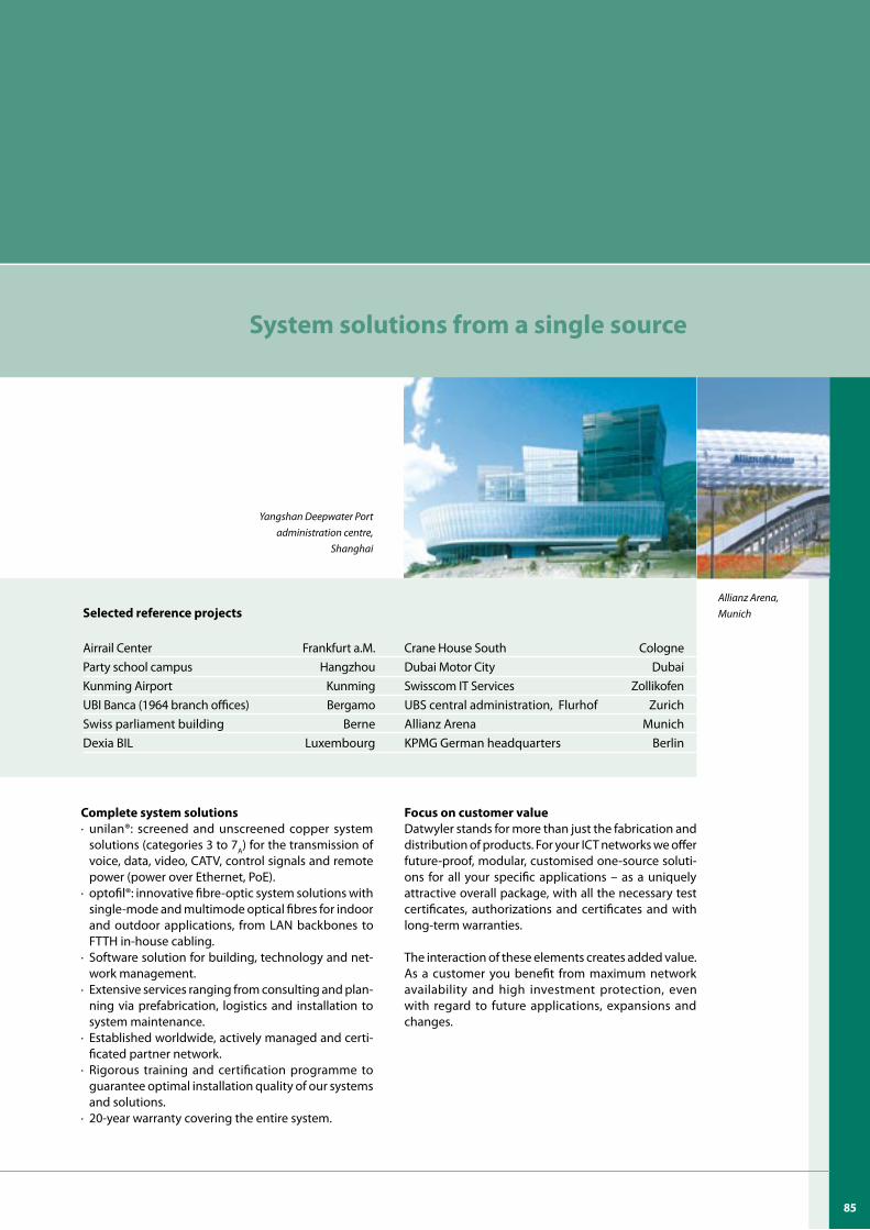
Focus on customer value Datwyler stands for more than just the fabrication and distribution of products. For your ICT networks we offer future-proof, modular, customised one-source soluti-ons for all your specific applications – as a uniquely attractive overall package, with all the necessary test certificates, authorizations and certificates and with long-term warranties.
The interaction of these elements creates added value. As a customer you benefit from maximum network availability and high investment protection, even with regard to future applications, expansions and changes.
System solutions from a single source
Complete system solutions· unilan®: screened and unscreened copper system
solutions (categories 3 to 7A) for the transmission of voice, data, video, CATV, control signals and remote power (power over Ethernet, PoE).
· optofil®: innovative fibre-optic system solutions with single-mode and multimode optical fibres for indoor and outdoor applications, from LAN backbones to FTTH in-house cabling.
· Software solution for building, technology and net-work management.
· Extensive services ranging from consulting and plan-ning via prefabrication, logistics and installation to system maintenance.
· Established worldwide, actively managed and certi-ficated partner network.
· Rigorous training and certification programme to guarantee optimal installation quality of our systems and solutions.
· 20-year warranty covering the entire system.
Yangshan Deepwater Port administration centre,
Shanghai
Allianz Arena, MunichSelected reference projects
Airrail Center Frankfurt a.M. Crane House South CologneParty school campus Hangzhou Dubai Motor City DubaiKunming Airport Kunming Swisscom IT Services ZollikofenUBI Banca (1964 branch offices) Bergamo UBS central administration, Flurhof ZurichSwiss parliament building Berne Allianz Arena MunichDexia BIL Luxembourg KPMG German headquarters Berlin
8�
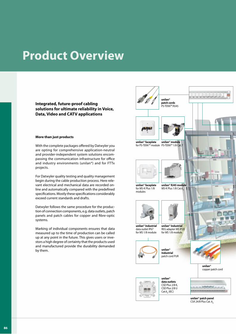
Product Overview
unilan®copper patch cord
unilan® IndustrialREG adapter MS IP20for MS 1/8 module
unilan® Industrialdata outlet IP67for MS 1/8 module
unilan® RJ4� moduleMS-K Plus 1/8 Cat.6A
unilan® faceplatefor MS-K Plus 1/8 modules
unilan® modulePS-TERATM 1/8 Cat.7
unilan® Industrialpatch cord PUR
unilan® patch cordsPS-TERATM/RJ45
unilan® faceplate for PS-TERATM module
unilan® data outletsCSD Plus 2/8 K, CSD Plus 2/8 U Cat.6A (IEC)
unilan® patch panel CSA 24/8 Plus Cat. 6A
Integrated, future-proof cabling solutions for ultimate reliability in Voice, Data, Video and CATV applications
More than just products
With the complete packages offered by Datwyler you are opting for comprehensive application-neutral and provider-independent system solutions encom-passing the communication infrastructure for office and industry environments (unilan®) and for FTTx projects.
For Datwyler quality testing and quality management begin during the cable production process. Here rele-vant electrical and mechanical data are recorded on-line and automatically compared with the predefined specifications. Mostly these specifications considerably exceed current standards and drafts.
Datwyler follows the same procedure for the produc-tion of connection components, e.g. data outlets, patch panels and patch cables for copper and fibre-optic systems.
Marking of individual components ensures that data measured up to the time of production can be called up at any point in the future. This gives users or inve-stors a high degree of certainty that the products used and manufactured provide the durability demanded by them.
86
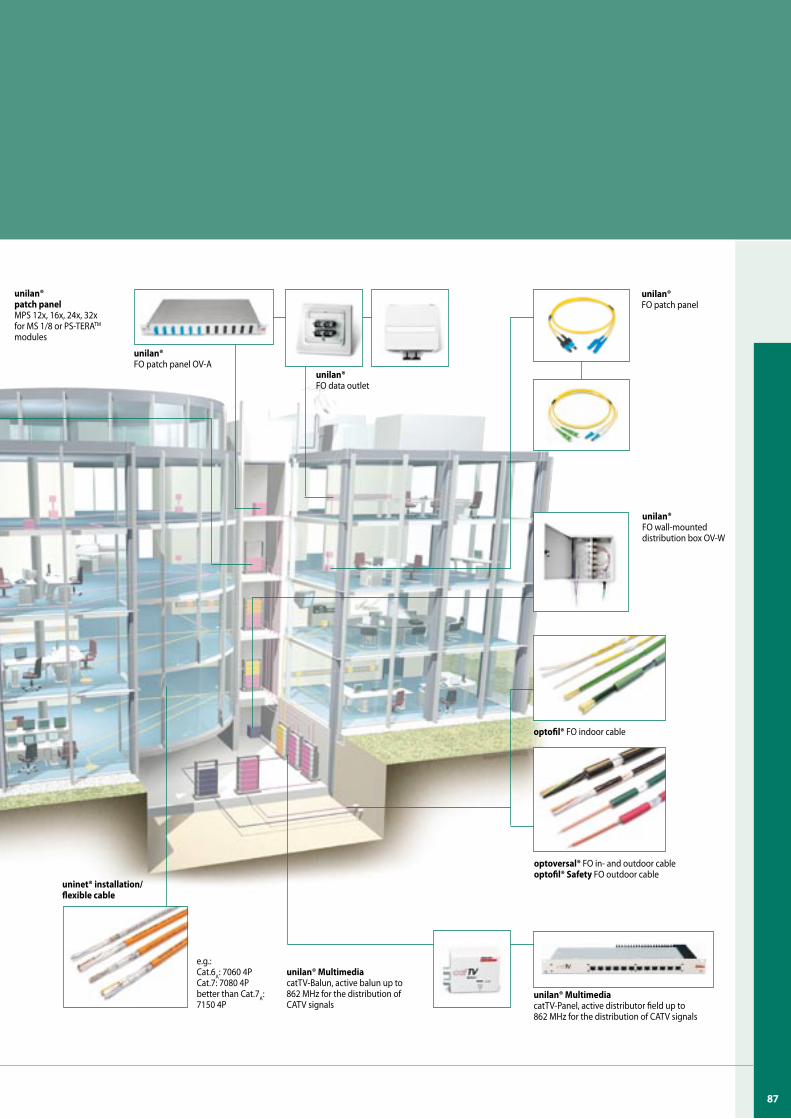
unilan® patch panelMPS 12x, 16x, 24x, 32x for MS 1/8 or PS-TERATM modules
unilan®FO patch panel OV-A
e.g.:Cat.6A: 7060 4PCat.7: 7080 4Pbetter than Cat.7A: 7150 4P
unilan® FO data outlet
unilan® MultimediacatTV-Balun, active balun up to 862 MHz for the distribution of CATV signals
optofil® FO indoor cable
optoversal® FO in- and outdoor cableoptofil® Safety FO outdoor cable
unilan®FO patch panel
unilan® MultimediacatTV-Panel, active distributor field up to 862 MHz for the distribution of CATV signals
unilan® FO wall-mounted distribution box OV-W
uninet® installation/flexible cable
8�
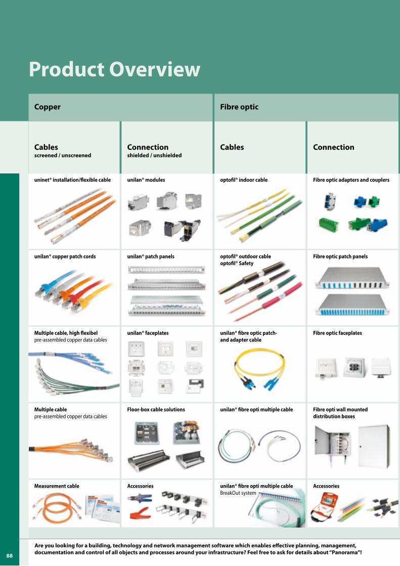
Product Overview
Floor-box cable solutions
unilan® faceplates
unilan® patch panels
unilan® modules
Accessories
ConnectionCablesConnectionshielded / unshielded
Cablesscreened / unscreened
Multiple cable, high flexibelpre-assembled copper data cables
unilan® copper patch cords
uninet® installation/flexible cable
Fibre opticCopper
Fibre opti wall mounted distribution boxes
Fibre optic faceplates
Fibre optic patch panels
Fibre optic adapters and couplers
Accessories
unilan® fibre opti multiple cable
unilan® fibre optic patch- and adapter cable
optofil® outdoor cableoptofil® Safety
optofil® indoor cable
unilan® fibre opti multiple cableBreakOut system
Measurement cable
Multiple cablepre-assembled copper data cables
Are you looking for a building, technology and network management software which enables effective planning, management, documentation and control of all objects and processes around your infrastructure? Feel free to ask for details about “Panorama”! 88
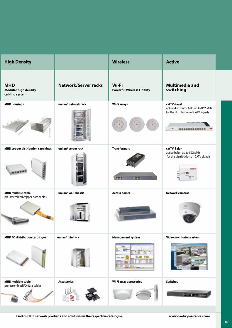
Multimedia and switching
Wi-FiPowerful Wireless Fidelity
Video monitoring system
Network cameras
catTV-Balunactive balun up to 862 MHz for the distribution of CATV signals
catTV-Panelactive distributor field up to 862 MHz for the distribution of CATV signals
Management system
Access points
Transformers
Wi-Fi arrays
Wi-Fi array accessories
Wireless Active
Network/Server racks
unilan® minirack
unilan® wall chassis
unilan® server rack
unilan® network rack
Accessories
MHD FO distribution cartridges
MHD multiple cablepre-assembled copper data cables
MHD copper distribution cartridges
MHD housings
MHD multiple cablepre-assembled FO data cables
MHDModular high density cabling system
High Density
Find our ICT network products and solutions in the respective catalogue. www.daetwyler-cables.com
Switches
89

U-9090U-9090
Safety cable systems
Leading know-howAs a provider of total solutions for safety cable systems, Datwyler possesses comprehensive know-how accu-mulated over decades: · Co-development of extended functional integrity
tests in collaboration with renowned testing institutes in the early 1990s.
· Sound knowledge of safety engineering and building codes and standards.
· Leading material, production and process know-how in the fabrication of safety cables incorporating pa-tented and proven ceramic technology.
· Development of the first metal-free fibre-optic cable with E30 extended functional integrity through com-bining existing technical competence in data and safety engineering.
· Broad systems competence. · Collaboration with renowned technical universities,
international standard committees and independent testing institutes.
Diverse applications Datwyler safety cable systems with extended functio-nal integrity are used wherever stringent fire-safety requirements must be met and people and property could be at risk due to fire and smoke: · Airports, train stations, metro stations · Hotels and hospitals · Sports stadiums, theatres and concert halls · Office and exhibition buildings, public buildings · Tunnels for road and rail
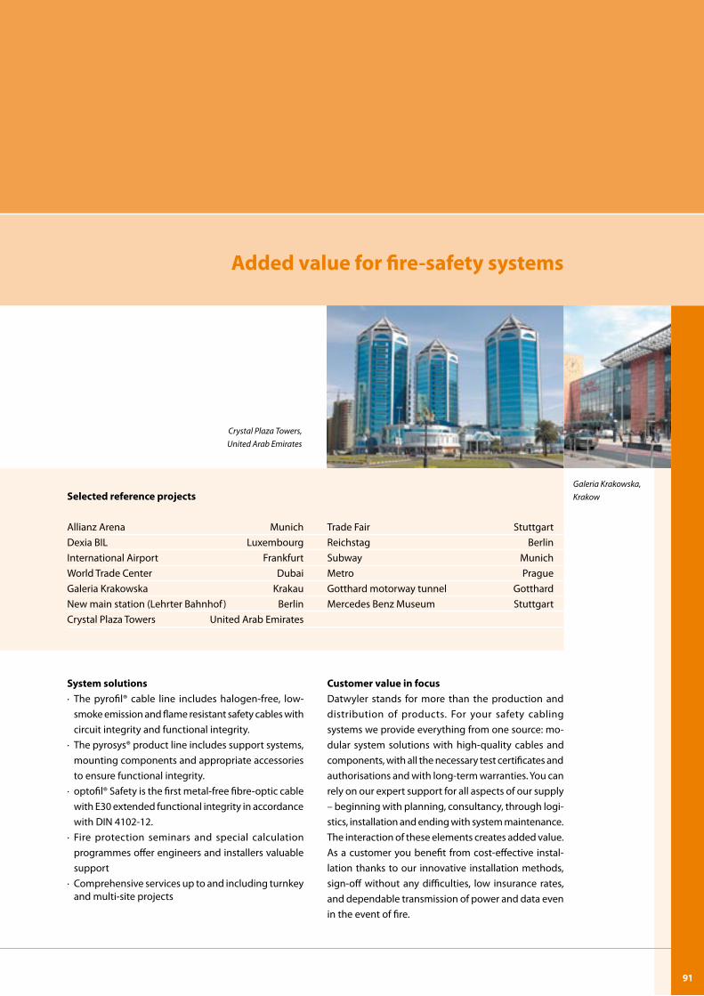
9�
Added value for fire-safety systems
System solutions· The pyrofil® cable line includes halogen-free, low-
smoke emission and flame resistant safety cables with circuit integrity and functional integrity.
· The pyrosys® product line includes support systems, mounting components and appropriate accessories to ensure functional integrity.
· optofil® Safety is the first metal-free fibre-optic cable with E30 extended functional integrity in accordance with DIN 4102-12.
· Fire protection seminars and special calculation programmes offer engineers and installers valuable support
· Comprehensive services up to and including turnkey and multi-site projects
Customer value in focus Datwyler stands for more than the production and distribution of products. For your safety cabling systems we provide everything from one source: mo-dular system solutions with high-quality cables and components, with all the necessary test certificates and authorisations and with long-term warranties. You can rely on our expert support for all aspects of our supply – beginning with planning, consultancy, through logi-stics, installation and ending with system maintenance. The interaction of these elements creates added value. As a customer you benefit from cost-effective instal-lation thanks to our innovative installation methods, sign-off without any difficulties, low insurance rates, and dependable transmission of power and data even in the event of fire.
Selected reference projects
Allianz Arena Munich Trade Fair StuttgartDexia BIL Luxembourg Reichstag BerlinInternational Airport Frankfurt Subway MunichWorld Trade Center Dubai Metro PragueGaleria Krakowska Krakau Gotthard motorway tunnel GotthardNew main station (Lehrter Bahnhof) Berlin Mercedes Benz Museum StuttgartCrystal Plaza Towers United Arab Emirates
Crystal Plaza Towers,United Arab Emirates
Galeria Krakowska,Krakow
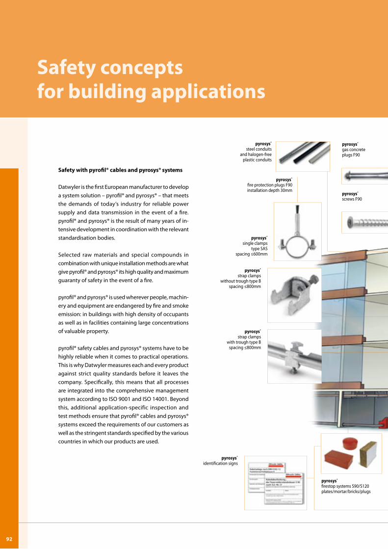
U-9292
Safety concepts for building applications
Safety with pyrofil® cables and pyrosys® systems
Datwyler is the first European manufacturer to develop a system solution – pyrofil® and pyrosys® – that meets the demands of today‘s industry for reliable power supply and data transmission in the event of a fire. pyrofil® and pyrosys® is the result of many years of in-tensive development in coordination with the relevant standardisation bodies.
Selected raw materials and special compounds in combination with unique installation methods are what give pyrofil® and pyrosys® its high quality and maximum guaranty of safety in the event of a fire.
pyrofil® and pyrosys® is used wherever people, machin-ery and equipment are endangered by fire and smoke emission: in buildings with high density of occupants as well as in facilities containing large concentrations of valuable property.
pyrofil® safety cables and pyrosys® systems have to be highly reliable when it comes to practical operations. This is why Datwyler measures each and every product against strict quality standards before it leaves the company. Specifically, this means that all processes are integrated into the comprehensive management system according to ISO 9001 and ISO 14001. Beyond this, additional application-specific inspection and test methods ensure that pyrofil® cables and pyrosys® systems exceed the requirements of our customers as well as the stringent standards specified by the various countries in which our products are used.
pyrosys®
steel conduitsand halogen-free
plastic conduits
pyrosys®
fire protection plugs F90installation depth 30mm
pyrosys®
single clampstype SAS
spacing ≤600mm
pyrosys®
strap clamps with trough type B
spacing ≤800mm
pyrosys®
firestop systems S90/S120 plates/mortar/bricks/plugs
pyrosys®
screws F90
pyrosys®
strap clamps without trough type B
spacing ≤800mm
pyrosys®
identification signs
pyrosys®
gas concrete plugs F90
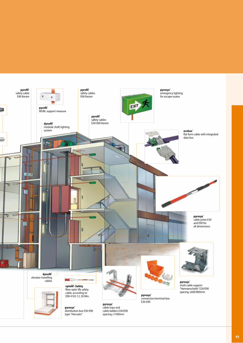
93
pyrofil®
safety cables E30-E60 Keram
pyrosys®
emergency lightingfor escape routes
ecobus® flat form cable with integrated data bus
pyrosys®
cable joints E30 and E90 for all dimensions
pyrosys®
cable trays andcable ladders E30/E90 spacing ≤1500mm
dynofil®
elevator travelling cables
optofil®-Safetyfibre optic life safety cable, according to DIN 4102-12, 30 Min.
pyrosys®
multi cable support”Hermanschelle“ E30/E90 spacing ≤600/800mm
pyrosys®
connection/terminal box E30-E90
pyrofil®
safety cables E90 Keram
dynofil®
modular shaft lighting system
pyrosys®
distribution box E30-E90type ”Hercules“
pyrofil®
WUM, support measure
pyrofil®
safety cable E90 Keram
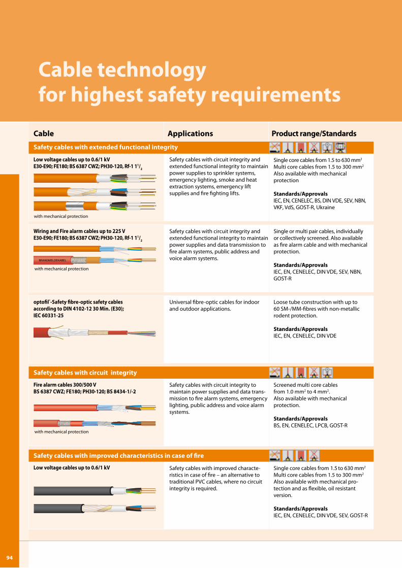
U-9494
BRANDMELDEKABEL
Cable technology for highest safety requirements
with mechanical protection
Applications Product range/StandardsCable
Single core cables from 1.5 to 630 mm2
Multi core cables from 1.5 to 300 mm2
Also available with mechanical protection
Standards/ApprovalsIEC, EN, CENELEC, BS, DIN VDE, SEV, NBN, VKF, VdS, GOST-R, Ukraine
Safety cables with circuit integrity and extended functional integrity to maintain power supplies to sprinkler systems, emergency lighting, smoke and heat extraction systems, emergency lift supplies and fire fighting lifts.
Single or multi pair cables, individually or collectively screened. Also available as fire alarm cable and with mechanical protection.
Standards/ApprovalsIEC, EN, CENELEC, DIN VDE, SEV, NBN, GOST-R
Loose tube construction with up to 60 SM-/MM-fibres with non-metallic rodent protection.
Standards/ApprovalsIEC, EN, CENELEC, DIN VDE
Universal fibre-optic cables for indoor and outdoor applications.
Screened multi core cables from 1.0 mm2 to 4 mm2. Also available with mechanical protection.
Standards/ApprovalsBS, EN, CENELEC, LPCB, GOST-R
Safety cables with circuit integrity to maintain power supplies and data trans-mission to fire alarm systems, emergency lighting, public address and voice alarm systems.
Single core cables from 1.5 to 630 mm2
Multi core cables from 1.5 to 300 mm2
Also available with mechanical pro- tection and as flexible, oil resistant version.
Standards/ApprovalsIEC, EN, CENELEC, DIN VDE, SEV, GOST-R
Safety cables with improved characte-ristics in case of fire – an alternative to traditional PVC cables, where no circuit integrity is required.
Safety cables with circuit integrity and extended functional integrity to maintain power supplies and data transmission to fire alarm systems, public address and voice alarm systems.
Safety cables with improved characteristics in case of fire
Low voltage cables up to 0.6/� kVE30-E90; FE�80; BS 638� CWZ; PH30-�20, Rf-� ��/2
Wiring and Fire alarm cables up to 22� VE30-E90; FE�80; BS 638� CWZ; PH30-�20, Rf-� ��/2
optofil®-Safety fibre-optic safety cables according to DIN 4�02-�2 30 Min. (E30); IEC 6033�-2�
Fire alarm cables 300/�00 VBS 638� CWZ; FE�80; PH30-�20; BS 8434-�/-2
Low voltage cables up to 0.6/� kV
with mechanical protection
Safety cables with extended functional integrity
Safety cables with circuit integrity
with mechanical protection
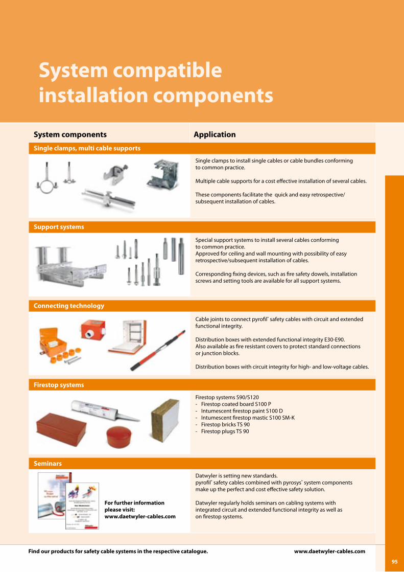
9�
ApplicationSystem components
Single clamps, multi cable supports
Support systems
Connecting technology
Firestop systems
Seminars
Single clamps to install single cables or cable bundles conforming to common practice.
Multiple cable supports for a cost effective installation of several cables.
These components facilitate the quick and easy retrospective/subsequent installation of cables.
Special support systems to install several cables conforming to common practice. Approved for ceiling and wall mounting with possibility of easy retrospective/subsequent installation of cables.
Corresponding fixing devices, such as fire safety dowels, installation screws and setting tools are available for all support systems.
Cable joints to connect pyrofil® safety cables with circuit and extended functional integrity.
Distribution boxes with extended functional integrity E30-E90. Also available as fire resistant covers to protect standard connections or junction blocks.
Distribution boxes with circuit integrity for high- and low-voltage cables.
Firestop systems S90/S120- Firestop coated board S100 P- Intumescent firestop paint S100 D- Intumescent firestop mastic S100 SM-K- Firestop bricks TS 90- Firestop plugs TS 90
Datwyler is setting new standards. pyrofil® safety cables combined with pyrosys® system components make up the perfect and cost effective safety solution.
Datwyler regularly holds seminars on cabling systems with integrated circuit and extended functional integrity as well as on firestop systems.
System compatible installation components
For further informationplease visit: www.daetwyler-cables.com
Find our products for safety cable systems in the respective catalogue. www.daetwyler-cables.com
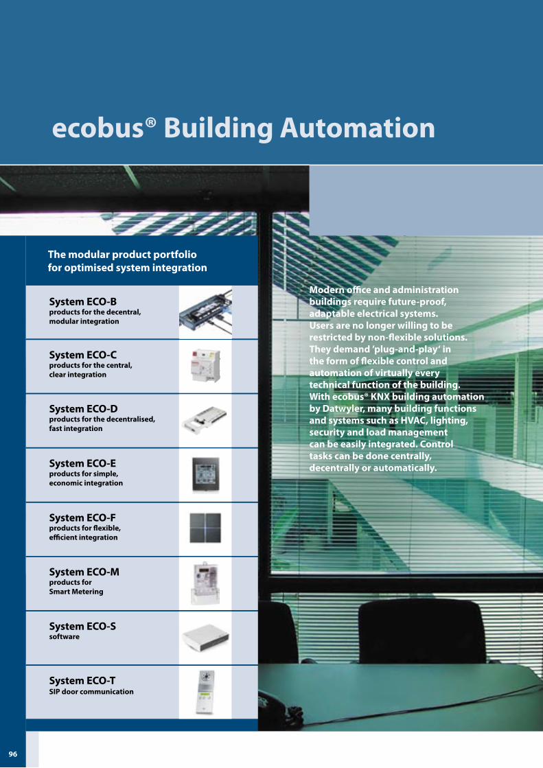
U-9696
ecobus® Building Automation
Modern office and administration buildings require future-proof, adaptable electrical systems. Users are no longer willing to be restricted by non-flexible solutions. They demand ’plug-and-play‘ in the form of flexible control and automation of virtually every technical function of the building. With ecobus® KNX building automation by Datwyler, many building functions and systems such as HVAC, lighting, security and load management can be easily integrated. Control tasks can be done centrally, decentrally or automatically.
The modular product portfolio for optimised system integration
System ECO-Eproducts for simple,economic integration
System ECO-Ssoftware
System ECO-Fproducts for flexible,efficient integration
System ECO-TSIP door communication
System ECO-Mproducts for Smart Metering
System ECO-Cproducts for the central, clear integration
System ECO-Dproducts for the decentralised, fast integration
System ECO-Bproducts for the decentral, modular integration
9�
Maximum flexibility in installation
Sony Center, BerlinSelected reference projects
MDR Erfurt Daimler Chrysler Stuttgart NBV UGA Herongen Frankfurt Stock Exchange FrankfurtPetronas Towers Kuala Lumpur Sony Center Berlin
for every project. Combined with ecobus® flatform cable systems for power distribution and data transmission and with Datwyler´s control and visualisation software which makes various systems available on one platform, the ecobus® product portfolio meets all requirements of intelligent building automation.
Customer value in focusDatwyler stands for more than the production and distribution of high-quality products. For your technical building systems we provide modular total solutions from one source, including consulting, support, logistics, warranty and turnkey responsibility if required.
Integrating these elements into sophisticated attractive overall packages creates added value. As a customer you benefit from: - drastically reduced cabling - the use of factory-ready modules - easier planning and documentation - reduced installation time- high flexibility, rapid changeability and adaptability- higher safety due to lower fire loads- cost-saving operation- lower power consumption- cost-effectiveness due to customized total solutions- long-term investment protection
Leading know-howAs a provider of total solutions for the electrical and communications infrastructure of public and commer-cial buildings, Datwyler possesses leading know-how acquired over decades. Applying our competence in materials, production and processing in the fabrication of flat and round cables, we have developed the ecobus® system, a comprehensive solution combining flexible power distribution with control and automation of all building functions.
Complete system solutions Decentral, modular and pluggable – with ecobus®, Datwyler offers sustainable system solutions tailored to changing customer needs, upcoming technologies and energy-efficient operation. Thus, ecobus® system solutions ensure high operational reliability and low operational costs.
Diverse applicationsIn recent years Datwyler has extended its proven ecobus® portfolio to include eight product groups for building automation based on the KNX standard. These product groups are used in system solutions for basic infrastructure as well as tenant improvements, including a wealth of applications such as responsive lighting, intelligent shading, HVAC, connections to third party systems, visualisation, power data metering and door communication via SIP. The product groups have a mo-dular structure and can be deployed in any combination. This makes it possible to achieve a cost-effective solution

U-9898
ecobus® Product Overview
System description
Modern building services installation calls for con-trol and automation of the widest possible range of functions. Whereas conventional electrical building services installation merely distributes power and could be switched if necessary, the ecobus® system meets the higher standards demanded of modern building services.
Compared with conventional electrical installation, modern building management using ecobus® fea-tures a minimum of cable expenditure, rapid adap-tability, and flexible use of space. This guarantees that your investment will retain its value for decades to come.
ecobus® enables the problem-free linking of a very wide variety of building services functions and faci-lities that have been strictly separated to date – such as heating, air conditioning, ventilation, lighting, building surveillance, and load management. Open and closed-loop control operations can be centralised or decentralised.
The flatform cables and appropriate pre-assembled plug-in and screw components make insulation stripping unnecessary and considerably reduce in-stallation time. The installations can be modified or extended without any major planning effort.
The modular ecobus® product portfolio enables optimised system integration. The portfolio ranges from pre-configured plug-and-play solutions for de-centralised systems, to cost-effective semi-centralised room solutions – e.g. for hotels, hospitals and office buildings – to total solutions for centralised building automation systems.
ecobus® Power �x�0flatform power cable �x�0mm2
e.g. for power supplies
ecobus® Data flatform cablewith ecobus® Data Adapteroutgoing circuit without insulation stripping for inter-connecting the sensors with flatform data trans-mission cables
ecobus® Combi Adapter �x2.�+2x0.�combined data and power output circuit for ecobus® Combi flatform cables
System ECO-Cproducts for the central, clear integra-tion
System ECO-Eproducts for simple,economic integration
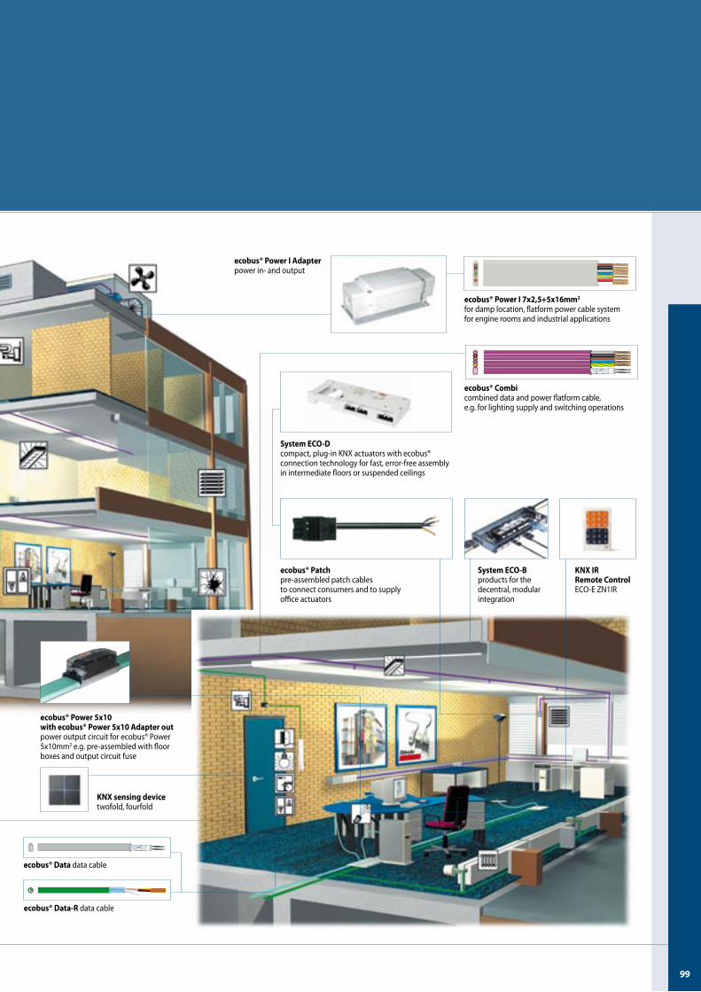
99
System ECO-Dcompact, plug-in KNX actuators with ecobus®connection technology for fast, error-free assembly in intermediate floors or suspended ceilings
ecobus® Power I Adapterpower in- and output
ecobus® Power I �x2,�+�x�6mm2
for damp location, flatform power cable system for engine rooms and industrial applications
ecobus® Patchpre-assembled patch cables to connect consumers and to supply office actuators
System ECO-Bproducts for the decentral, modular integration
KNX IR Remote ControlECO-E ZN1IR
ecobus® Power �x�0 with ecobus® Power �x�0 Adapter outpower output circuit for ecobus® Power 5x10mm2 e.g. pre-assembled with floor boxes and output circuit fuse
ecobus® Data data cable
ecobus® Data-R data cable
KNX sensing device twofold, fourfold
ecobus® Combicombined data and power flatform cable, e.g. for lighting supply and switching operations
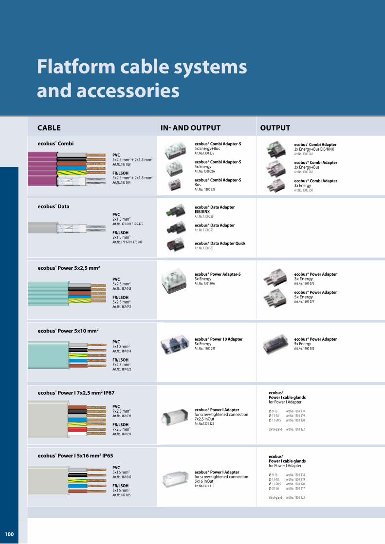
ecobus® Combi
ecobus® Data
ecobus® Power �x2,� mm2
ecobus® Power �x�0 mm2
ecobus® Power I �x2,� mm2 IP6�
ecobus® Power I �x�6 mm2 IP6�
U-�00�00
Flatform cable systems and accessories
IN- AND OUTPUT OUTPUTCABLE
ecobus® Combi Adapter3x Energy+BusArt.No. 1300 282
ecobus® Combi Adapter3x Energy+Bus EIB/KNXArt.No. 1300 282
ecobus® Combi Adapter3x EnergyArt.No. 1300 350
ecobus® Combi Adapter-S5x EnergyArt.No.1300236
ecobus® Combi Adapter-S5x Energy+BusArt.No.1300235
ecobus® Combi Adapter-SBusArt.No.1300237
ecobus® Data Adapter Art.No. 1300 353
ecobus® Data Adapter EIB/KNXArt.No. 1300 286
ecobus® Data Adapter QuickArt.No. 1300 303
ecobus® Power Adapter-S5x EnergyArt.No.1301076
ecobus® Power Adapter5x EnergyArt.No.1301077
ecobus® Power Adapter3x EnergyArt.No.1301075
ecobus® Power �0 Adapter5x EnergyArt.No..1300295
ecobus® Power Adapter5x EnergyArt.No.1300302
ecobus® Power I cable glandsfor Power I Adapter
Ø 9-16 Art.No. 1301 318Ø 13-18 Art.No. 1301 319Ø 11-20,5 Art.No. 1301 320
Blind-gland Art.No. 1301 322
ecobus® Power I Adapterfor screw-tightened connection7x2,5 InOutArt.No.1301325
ecobus® Power I cable glandsfor Power I Adapter
Ø 9-16 Art.No. 1301 318Ø 13-18 Art.No. 1301 319Ø 11-20,5 Art.No. 1301 320Ø 20-26 Art.No. 1301 317
Blind-gland Art.No. 1301 322
ecobus® Power I Adapterfor screw-tightened connection5x16 InOutArt.No.1301316
PVC5x2,5 mm2 + 2x1,5 mm2
Art.No.187028
FR/LSOH5x2,5 mm2 + 2x1,5 mm2
Art.No.187034
PVC2x1,5 mm2
Art.No.179669/175475
FR/LSOH2x1,5 mm2
Art.No.179679/176900
PVC5x2,5 mm2
Art.No.187048
FR/LSOH5x2,5 mm2
Art.No.187053
PVC5x10 mm2
Art.No.187014
FR/LSOH5x2,5 mm2
Art.No.187022
PVC7x2,5 mm2
Art.No.187039
FR/LSOH7x2,5 mm2
Art.No.187059
PVC5x16 mm2
Art.No.187045
FR/LSOH5x16 mm2
Art.No.187025
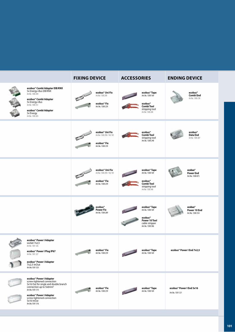
�0�
FIXING DEVICE ACCESSORIES ENDING DEVICE
ecobus® Combi EndArt.No. 1300 238
ecobus® TapeArt.No.1300169
ecobus® Combi Toolstripping toolArt.No. 1300 240
ecobus® FixArt.No.1300239
ecobus® Uni FixArt.No. 1300 290
ecobus® Combi Adapter5x Energy+BusArt.No. 1300 351
ecobus® Combi Adapter EIB/KNX 5x Energy+Bus EIB/KNXArt.No. 1300 284
ecobus® Combi Adapter5x EnergyArt.No. 1300 283
ecobus® Data EndArt.No. 1300 287
ecobus® Combi Toolstripping toolArt.No.1300240
ecobus® FixArt.No.1300239
ecobus® Uni FixArt.No. 1300 290 / 182 181
ecobus® Power EndArt.No.1300875
ecobus® TapeArt.No.1300169
ecobus® Combi Toolstripping toolArt.No. 1300 240
ecobus® FixArt.No.1300239
ecobus® Uni FixArt.No. 1300 290 / 182 181
ecobus® Power �0 EndArt.No.1300354
ecobus® TapeArt.No.1300169
ecobus® Power �0 Toolcable stripperArt.No.1300306
ecobus® Power FixArt.No.1300289
ecobus® Power I End �x2,�ecobus® TapeArt.No.1300169
ecobus® FixArt.No.1300239
ecobus® Power I Plug IP6�Art.No. 1301 327
ecobus® Power I Adapter socket 7x2,5Art.No. 1301 326
ecobus® Power I Adapter7x2,5 InOutArt.No.1301325
ecobus® TapeArt.No.1300169
ecobus® FixArt.No.1300239
ecobus® Power I End �x�6
Art.No.1301321
ecobus® Power I Adapterscrew-tightened connection5x16 Out for single and double branch connection up to 5x6mm2
Art.No.1301315
ecobus® Power I Adapterscrew-tightened connection5x16 InOutArt.No.1301316
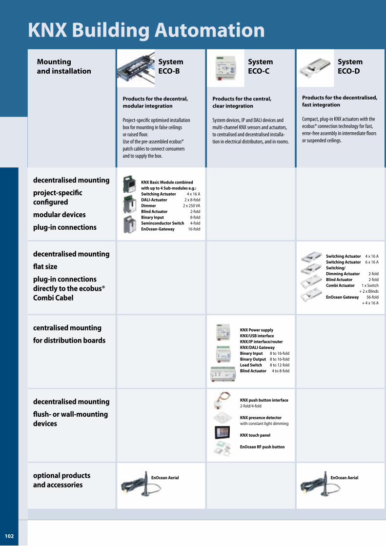
U-�02�02
KNX Building AutomationSystem ECO-B
Products for the decentral, modular integration
Project-specificoptimisedinstallationboxformountinginfalseceilingsorraisedfloor.Useofthepre-assembledecobus®patchcablestoconnectconsumersandtosupplythebox.
Mounting and installation
KNX Basic Module combined with up to 4 Sub-modules e.g.:Switching Actuator 4 x 16 ADALI-Actuator 2 x 8-foldDimmer 2 x 250 VABlind Actuator 2-foldBinary Input 8-foldSeminconductor Switch 4-foldEnOcean-Gateway 16-fold
decentralised mounting
flush- or wall-mountingdevices
centralised mounting
for distribution boards
decentralised mounting
flat size
plug-in connectionsdirectly to the ecobus® Combi Cabel
decentralised mounting
project-specificconfigured
modular devices
plug-in connections
optional productsand accessories
EnOcean Aerial
System ECO-D
Products for the decentralised, fast integration
Compact,plug-inKNXactuatorswiththeecobus®connectiontechnologyforfast,error-freeassemblyinintermediatefloorsorsuspendedceilings.
Switching Actuator 4 x 16 ASwitching Actuator 6 x 16 ASwitching/Dimming Actuator 2-foldBlind Actuator 2-foldCombi Actuator 1 x Switch + 2 x BlindsEnOcean Gateway 56-fold + 4 x 16 A
EnOcean Aerial
KNX Power supplyKNX/USB interfaceKNX/IP interface/routerKNX/DALI GatewayBinary Input 8 to 16-foldBinary Output 8 to 16-foldLoad Switch 8 to 12-foldBlind Actuator 4 to 8-fold
System ECO-C
Products for the central, clear integration
Systemdevices,IPandDALIdevicesandmulti-channelKNXsensorsandactuators,tocentralisedanddecentralisedinstalla-tioninelectricaldistributors,andinrooms.
KNX push button interface2-fold/4-fold
KNX presence detector with constant light dimming
KNX touch panel
EnOcean RF push button
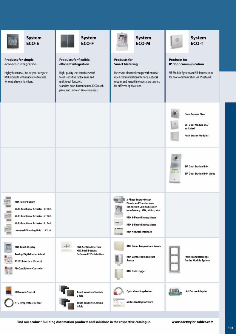
�03
KNX Touch Display
Analog/Digital Input 4-fold
RS232 Interface (Pronto)
Air Conditioner Controller
KNX Power Supply
Multi-functional Actuator 4 x 10 A
Multi-functional Actuator 6 x 10 A
Multi-functional Actuator 4 x 16 A
Universal Dimming Unit 400 VA
IR Remote Control
NTC temperature sensor
System ECO-E
Products for simple,economic integration
Highlyfunctional,buteasyto-integrateKNXproductswithinnovativefeaturesforcentralroomfunctions.
KNX Sentido InterfaceKNX Push ButtonsEnOcean RF Push button
Touch sensitive Sentido 2-fold
Touch sensitive Sentido 4-fold
System ECO-F
Products for flexible,efficient integration
High-qualityuserinterfaceswithtouch-sensitivetactilezoneandmultitouchfunction.Standardpush-buttonsensor,KNXtouchpanelandEnOceanWirelesssensors.
KNX Room Temperature Sensor
KNX Contact Temperature Sensor
KNX Data Logger
3-Phase Energy MeterDirect- and Transformer-connection Communication Interface e.g. KNX, M-Bus, et al.
KNX 3-Phase Energy Meter
KNX 3-Phase Energy Meter
KNX Network Interface
Optical reading device
M-Bus reading software
System ECO-M
Products for Smart Metering
Metersforelectricalenergywithstandar-disedcommunicationinterface,networkcouplerandversatiletemperaturesensorsfordifferentapplications.
Frames and Housings for the Module System
LAN Secure Adapter
System ECO-T
Products for IP door communication
SIPModuleSystemandSIPDoorstationsfordoorcommunicationviaIPnetwork.
Door Camera Steel
SIP Door Module ECO and Maxi
Push Button Modules
SIP Door Station IP�4
SIP Door Station IP�4 Video
www.daetwyler-cables.comFind our ecobus® Building Automation products and solutions in the respective catalogue. www.daetwyler-cables.com
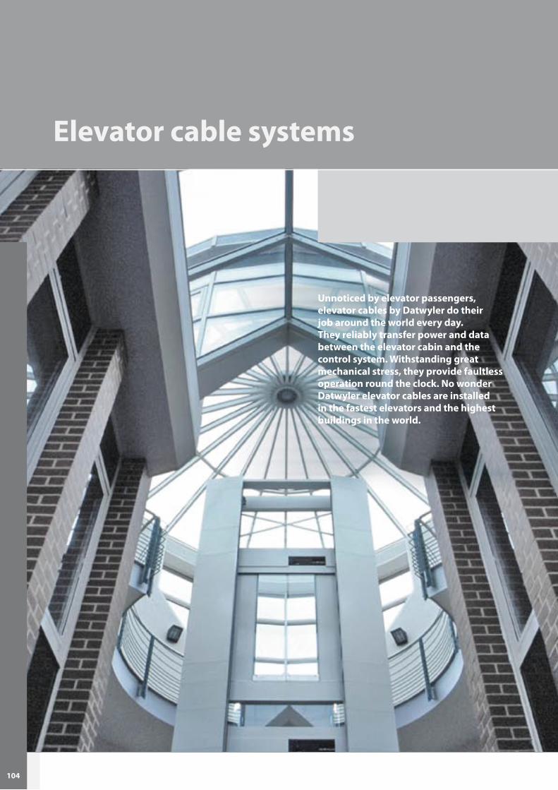
�04U-�04�04
Elevator cable systems
Unnoticed by elevator passengers, elevator cables by Datwyler do their job around the world every day. They reliably transfer power and data between the elevator cabin and the control system. Withstanding great mechanical stress, they provide faultless operation round the clock. No wonder Datwyler elevator cables are installed in the fastest elevators and the highest buildings in the world.
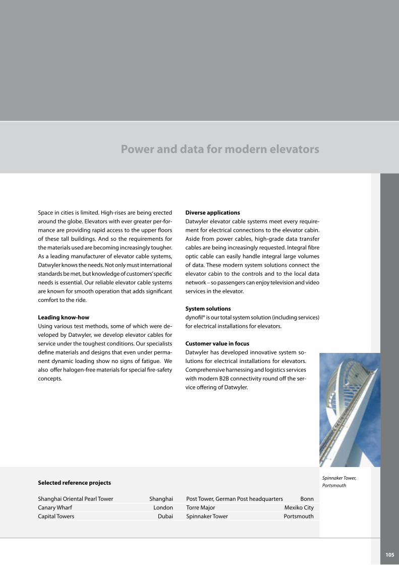
�0�
Power and data for modern elevators
Selected reference projects
Shanghai Oriental Pearl Tower Shanghai Post Tower, German Post headquarters BonnCanary Wharf London Torre Major Mexiko CityCapital Towers Dubai Spinnaker Tower Portsmouth
Diverse applications Datwyler elevator cable systems meet every require-ment for electrical connections to the elevator cabin. Aside from power cables, high-grade data transfer cables are being increasingly requested. Integral fibre optic cable can easily handle integral large volumes of data. These modern system solutions connect the elevator cabin to the controls and to the local data network – so passengers can enjoy television and video services in the elevator.
System solutionsdynofil® is our total system solution (including services) for electrical installations for elevators.
Customer value in focus Datwyler has developed innovative system so-lutions for electrical installations for elevators. Comprehensive harnessing and logistics services with modern B2B connectivity round off the ser-vice offering of Datwyler.
Space in cities is limited. High-rises are being erected around the globe. Elevators with ever greater per-for-mance are providing rapid access to the upper floors of these tall buildings. And so the requirements for the materials used are becoming increasingly tougher. As a leading manufacturer of elevator cable systems, Datwyler knows the needs. Not only must international standards be met, but knowledge of customers’ specific needs is essential. Our reliable elevator cable systems are known for smooth operation that adds significant comfort to the ride.
Leading know-how Using various test methods, some of which were de-veloped by Datwyler, we develop elevator cables for service under the toughest conditions. Our specialists define materials and designs that even under perma-nent dynamic loading show no signs of fatigue. We also offer halogen-free materials for special fire-safety concepts.
Spinnaker Tower, Portsmouth
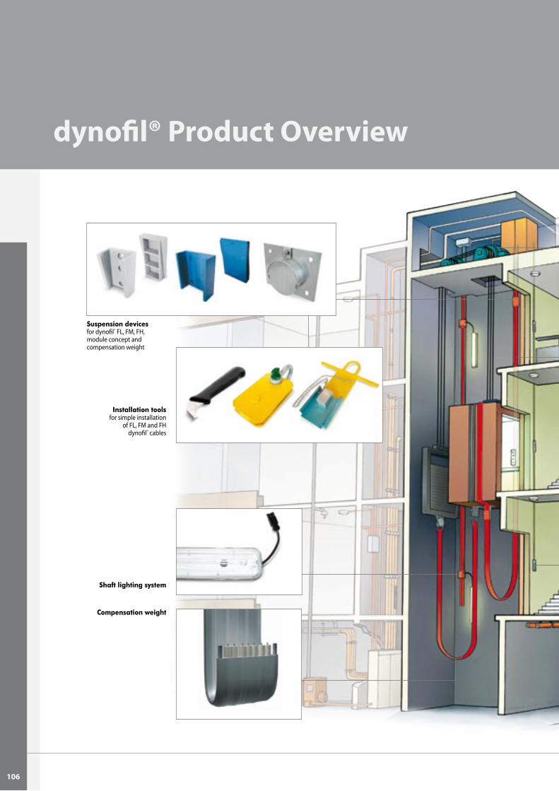
�06
dynofil® Product Overview
Shaft lighting system
Suspension devicesfor dynofil® FL, FM, FH, module concept and compensation weight
Compensation weight
Installation toolsfor simple installation
of FL, FM and FH dynofil® cables
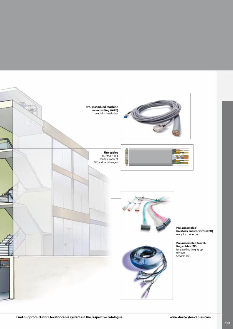
�0�
Pre-assembled travel-ling cables (TC)for travelling heights up to 400mServices see
Pre-assembled hoistway cables/wires (HW)ready for connection
Pre-assembled machine room cabling (MRC)
ready for installation
Flat cablesFL, FM, FH and
module conceptPVC and zero-halogen
Find our products for Elevator cable systems in the respective catalogue. www.daetwyler-cables.com
©20
11 D
atw
yler
- FT
TH-K
atal
og -
e - 0
5/20
11
SwiTzerland
datwyler Switzerland inc.Cabling SolutionsGotthardstrasse 31CH-6460 AltdorfT + 41-41-875 12 68F + 41-41-875 19 [email protected]
GreaT briTain
datwyler (UK) ltdUnit B Omega Enterprise Park Electron Way Chandlers Ford GB-Hampshire SO53 4SE T + 44-2380-279 999F + 44-2380-279 [email protected] www.daetwyler-cables.com
UniTed arab emiraTeS
datwyler middle eastCabling SolutionsRA08BB02 Jebel Ali Free ZoneP.O. Box 263480UAE-DubaiT + 971-4 887 0515F + 971-4 887 [email protected]
CHina
datwyler Cables+Systems (Shanghai) Co. ltdBuilding 16, No. 1-111, Kang Qiao Dong Road Kang Qiao Industrial Zone, Pudong CN-201319 Shanghai, P. R. China T + 86-21-6813 0066 F + 86-21-6813 [email protected] www.datwyler-china.com
datwyler (Suzhou) Cabling Systems Co. ltdBlock 31, 15# Dong Fu RoadSuzhou Singapore Industrial ParkCN-215123 Suzhou, P. R. ChinaT + 86-512-6265 3600F + 86-512-6265 [email protected]
SinGapore
datwyler (Thelma) Cables+Systems pte ltd29 Tech Park Crescent SG-638103 Singapore T + 65-6863 1166 F + 65-6897 [email protected] www.daetwyler-cables.com
Germany
dätwyler Cables GmbHAuf der Roos 4-12 DE-65795 Hattersheim T + 49-6190-88 80 0 F + 49-6190-88 80 [email protected] www.daetwyler-cables.com
dätwyler Cables GmbHLilienthalstraße 17DE-85399 HallbergmoosT + 49-811-99 86 33 0F + 49-811-99 86 33 [email protected]
aUSTria
dätwyler Cables GmbHoffice austriaTenschertstraße 8 AT-1230 Wien T + 43-1-810 16 41 0 F + 43-1-810 16 41 [email protected] www.daetwyler-cables.com
Subject to technical modification.