ftc fastrak compact - stiactuation.com manual_ftc.pdf · ftc – fastrak compact ......
TRANSCRIPT

FTC – FasTrak Compact INSTRUCTION MANUAL 4049

____________________________________________________________________________________ STI S.r.l. – Via Dei Caravaggi 15, 24040 Levate (BG) – ITALY www.imi-critical.com
Manual 4049, rev. 00 05/2017 – FTC i
STI S.r.l has taken every care in collecting and verifying the documentation contained in this Instruction
Manual. The information herein contained are reserved property of STI S.r.l.

____________________________________________________________________________________ STI S.r.l. – Via Dei Caravaggi 15, 24040 Levate (BG) – ITALY www.imi-critical.com
Manual 4049, rev. 00 05/2017 – FTC ii
INDEX
1 GENERAL INFORMATION .................................................................................................................. 1
1.1 GENERALITIES .................................................................................................................................. 1 1.2 MANUFACTURER ............................................................................................................................... 1 1.3 TERMS AND CONDITIONS ................................................................................................................... 1 1.4 MANUFACTURER’S LIABILITY .............................................................................................................. 1 1.5 APPLICABLE STANDARDS AND DIRECTIVES ........................................................................................ 2 1.6 SYMBOLOGY USED ............................................................................................................................ 2
2 DEVICE DESCRIPTION ....................................................................................................................... 3
3 TECHNICAL DATA ............................................................................................................................... 4
4 LABEL ................................................................................................................................................... 5
5 OPERATING CONDITIONS AND INTENDED USE ............................................................................. 6
5.1 OPERATING CONDITIONS ................................................................................................................... 6 5.2 INTENDED USE .................................................................................................................................. 6
6 TRANSPORT ........................................................................................................................................ 7
7 RECEPTION .......................................................................................................................................... 7
8 STORAGE ............................................................................................................................................. 7
9 INSTALLATION .................................................................................................................................... 8
9.1 CHECKS TO PERFORM BEFORE INSTALLATION ..................................................................................... 8 9.2 MOUNTING ON THE ACTUATOR ........................................................................................................... 8 9.3 EARTHLING CONNECTION ................................................................................................................ 10 9.4 PNEUMATIC CONNECTIONS .............................................................................................................. 11 9.5 ELECTRICAL CONNECTION ............................................................................................................... 12 9.6 SELF-TUNING GUIDE ....................................................................................................................... 13
10 INSTRUCTION FOR THE OPERATORS ....................................................................................... 15
10.1 FIELD ACTIVITIES ............................................................................................................................ 15 10.2 RESIDUAL RISKS ............................................................................................................................. 15
11 MAINTENANCE .............................................................................................................................. 16
11.1 PERIODIC INSPECTIONS AND MAINTENANCE ...................................................................................... 16 11.2 EXTRAORDINARY MAINTENANCE ...................................................................................................... 16
12 TROUBLESHOOTING .................................................................................................................... 17
13 SPARE PARTS ............................................................................................................................... 18
14 DECOMMISSIONING ...................................................................................................................... 19

_____________________________________________________________________________________ STI S.r.l. – Via Dei Caravaggi 15, 24040 Levate (BG) – ITALY www.imi-critical.com
Manual 4049, rev. 00 05/2017 – FTC - 1 -
1 GENERAL INFORMATION
Important This Instruction Manual is an integral part of the machine, it should be carefully
read before carrying out any operation and it should be kept for future
references. The operators shall adopt the safety precautions required by the
country where the product is installed.
This Instruction Manual is realized in accordance with the Directive 2006/42/CE.
1.1 Generalities
STI S.r.l. products are conceived, manufactured and controlled according to the Quality management
System in compliance with EN ISO 9001 International Standard.
1.2 Manufacturer
With respect to Machinery Directive 2006/42/EC, the Manufacturer of the described FasTrak Compact is
STI S.r.l. as specified on the label.
STI S.r.l. Via Dei Caravaggi 15 24040 Levate (BG) Italy Tel. +39 035 2928.2 Fax +39 035 2928.247 [email protected]
1.3 Terms and conditions
STI S.r.l. guarantees each single product to be free from defects and to conform to current goods
specifications. The warranty period is two years from the date of shipment to the first user. The warranty
does not cover special products or components not covered by warranty in their turn by subcontractors. No
warranty is given for products which have been subject to improper storage, improper installation, improper
maintenance or which have been modified or repaired by unauthorised personnel.
1.4 Manufacturer’s liability
STI S.r.l. declines all liability in the event of:
- use of the device in contravention of local safety at work legislation;
- incorrect installation, incorrect maintenance, disregard or incorrect application of the instructions
provided on the nameplate and in this manual;
- modifications or repairs without STI S.r.l. authorisation;
- work done on the unit by unqualified or unsuitable operators.
Considering that STI S.r.l. has no direct control over particular applications, operation or maintenance
conditions, it is the operator’s responsibility to comply with all applicable safety rules; it is the sole
responsibility of the operator to ensure that the local health and safety regulations are adhered to.
Depending on the specific working conditions, additional precautions may be requested.
Please inform STI S.r.l. urgently if you face unsafe situations not described in this Instruction Manual.

_____________________________________________________________________________________ STI S.r.l. – Via Dei Caravaggi 15, 24040 Levate (BG) – ITALY www.imi-critical.com
Manual 4049, rev. 00 05/2017 – FTC - 2 -
1.5 Applicable Standards and Directives
EN ISO 12100:2010 Safety of machinery - General principles for design - Risk assessment and risk
reduction
2006/95/EC Directive for Low Voltage Equipment (LV)
2004/108/EC Directive relating to the Electromagnetic Compatibility (EMC)
2014/34/CE Equipments used in potentially explosive atmospheres (ATEX)
1.6 Symbology used
Important
Be careful where these symbols are shown, they indicate a potentially hazardous
situation and they warn that if the steps are not properly performed, may result
causing serious injury, death or long-term risks to the health of exposed persons
GENERAL DANGER DANGER POWER SUPPLY CRUSHING HAZARD
Important
The operators shall adopt the safety precautions required by the country where
the product is installed.
The operators shall also adopt the following precautions.
Must wear protective clothing.
Must wear protective
gloves.
Must wear protective footwear.
Must wear protective helmet.
Must wear protective glasses
Must wear earplugs
_____________________________________________________________________________________ STI S.r.l. – Via Dei Caravaggi 15, 24040 Levate (BG) – ITALY www.imi-critical.com
Manual 4049, rev. 00 05/2017 – FTC - 3 -
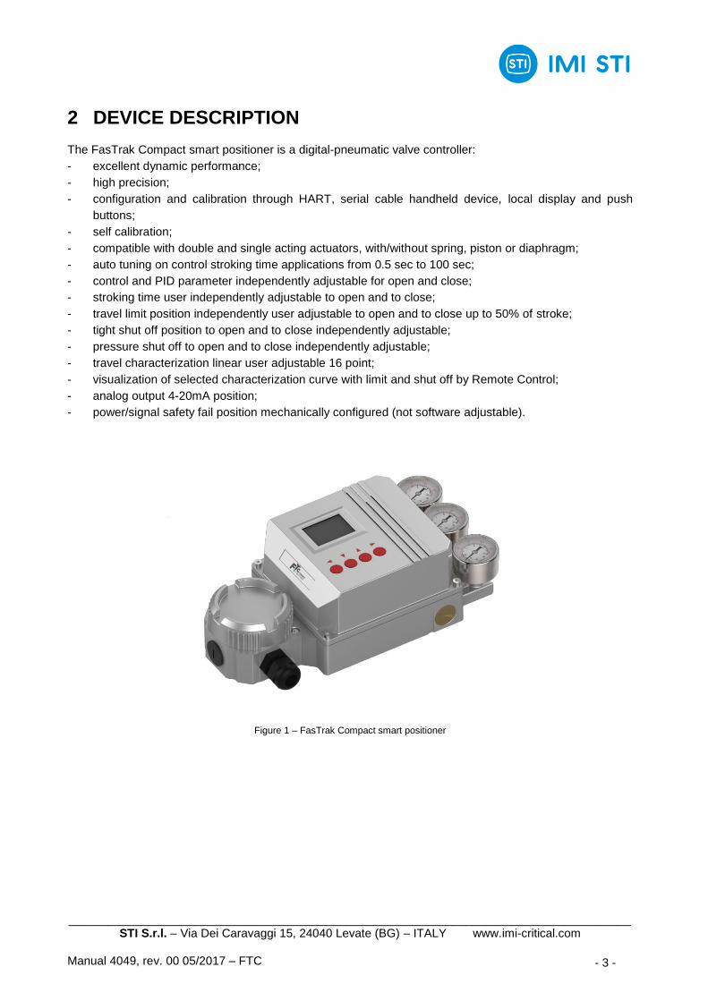
2 DEVICE DESCRIPTION
The FasTrak Compact smart positioner is a digital-pneumatic valve controller:
- excellent dynamic performance;
- high precision;
- configuration and calibration through HART, serial cable handheld device, local display and push
buttons;
- self calibration;
- compatible with double and single acting actuators, with/without spring, piston or diaphragm;
- auto tuning on control stroking time applications from 0.5 sec to 100 sec;
- control and PID parameter independently adjustable for open and close;
- stroking time user independently adjustable to open and to close;
- travel limit position independently user adjustable to open and to close up to 50% of stroke;
- tight shut off position to open and to close independently adjustable;
- pressure shut off to open and to close independently adjustable;
- travel characterization linear user adjustable 16 point;
- visualization of selected characterization curve with limit and shut off by Remote Control;
- analog output 4-20mA position;
- power/signal safety fail position mechanically configured (not software adjustable).
Figure 1 – FasTrak Compact smart positioner
_____________________________________________________________________________________ STI S.r.l. – Via Dei Caravaggi 15, 24040 Levate (BG) – ITALY www.imi-critical.com
Manual 4049, rev. 00 05/2017 – FTC - 4 -
3 TECHNICAL DATA
Connections Air supply
- POWER CONNECTION
- 2 wires from signal: 4-20mA (min 3.5 mA),
10÷30 VDC, impedance 500 ohm
- ELECTRICAL CONNECTION
- Signal metric ½” NPT
- Auxiliary output metric ½” NPT
- TTL RS232
- PNEUMATIC CONNECTION
- ¼” NPT female
- MOTIVE FLUID
- instrument air (*)
- nitrogen
- SUPPLY PRESSURE
- 2.5÷7 bar
- AIR CONSUMPTION
- < 0.7 Nm3/h at 4 bar
Input Output
- ANALOG INPUT
- 4÷20 mA DC
- ANALOG OUTPUT
- 4÷20 mA DC (passive loop 10÷26,5 V)
Stroke Movement Performance data according to IEC 61514-2 (***)
- FEEDBACK ROTATION ANGLE
- 30°÷115° (**)
- ADJUSTABLE SPEED
- range 0÷300 seconds
- individually configurable for each direction
- CHARACTERISTIC CURVE
- linear, equal percentage or configurable
- CONTROL PARAMETER
- individually configurable for each direction
- TRAVEL CONTROL
- min and max settable stroke limits of cut off
- SIGNAL FAIL
- end stroke limits (4 mA position)
- HYSTERESIS + DEADBAND
- ±0.15%
- REPEATIBILITY
- ±0.15%
- SENSITIVITY
- ±0.1%
- LINEARITY
- ±0.3%
- INFLUENCE OF TEMPERATURE
- ≤ 0.3% for every 10°C
- FLOW CAPABILITY
- 23.5 Nm3/h at 6bar (CV 0.3)
- ACTION
- configurable single or double
Environmental capabilities Other
- ENVIRONMENT
- protection IP65
- operating temperature: -40°C / +85°C
- storage temperature: -40°C / +85°C
- humidity up to 100%
- VIBRATIONS
- up to 2g (ISA-S75.13)
- LINKAGE
- for linear actuator (stroke 70÷1000 mm)
- for quarter turn actuators (VDE/VDI 3845)
- HIGH SPEED COMUNICATION KIT
Materials and weight
- MATERIAL
- aluminum with stainless steel feedback shaft
- WEIGHT
- 2,30 kg
(*) Use instrument air free from oil, water and dust according to ISO 8573-1 class 3 and with particle size ≤
5 µm. The maximum value of the pressure dew point shall be 10 °C lower than the operating temperature.
(**) Also < 30° (with lower resolution).
(***) For angle ≥ 90°.
_____________________________________________________________________________________ STI S.r.l. – Via Dei Caravaggi 15, 24040 Levate (BG) – ITALY www.imi-critical.com
Manual 4049, rev. 00 05/2017 – FTC - 5 -
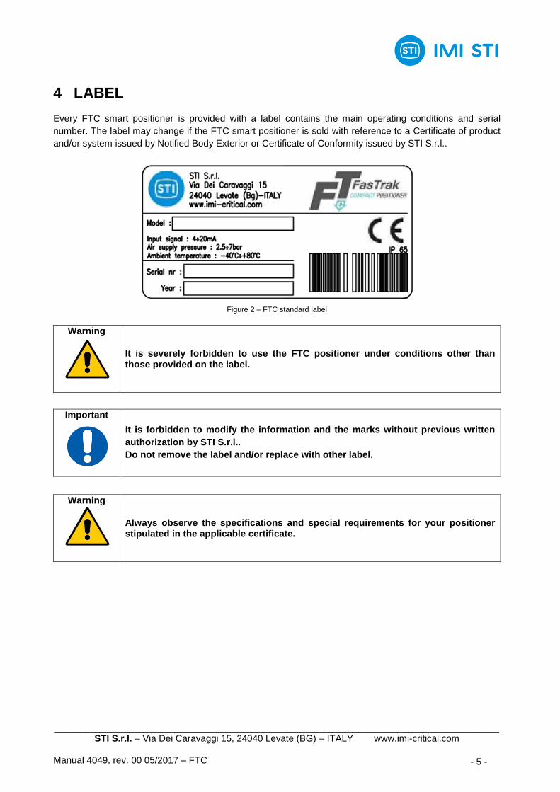
4 LABEL
Every FTC smart positioner is provided with a label contains the main operating conditions and serial
number. The label may change if the FTC smart positioner is sold with reference to a Certificate of product
and/or system issued by Notified Body Exterior or Certificate of Conformity issued by STI S.r.l..
Figure 2 – FTC standard label
Important
It is forbidden to modify the information and the marks without previous written
authorization by STI S.r.l..
Do not remove the label and/or replace with other label.
Warning
It is severely forbidden to use the FTC positioner under conditions other than those provided on the label.
Warning
Always observe the specifications and special requirements for your positioner stipulated in the applicable certificate.

_____________________________________________________________________________________ STI S.r.l. – Via Dei Caravaggi 15, 24040 Levate (BG) – ITALY www.imi-critical.com
Manual 4049, rev. 00 05/2017 – FTC - 6 -
5 OPERATING CONDITIONS AND INTENDED USE
5.1 Operating conditions
The label fastened on the FTC smart positioner contains the main operating conditions for the specified
application (see Section 4). Other operating conditions are reported on the documents accompanying the
FTC smart positioner. For general operating conditions see Section 3.
5.2 Intended use
The FTC smart positioner is an electro-pneumatic positioner designed to being mounted on actuators in
order to control the valve opening /closing as required.
Warning
It is severely forbidden to use the FTC smart positioner for purpose or application other than those for which it was designed and here specified.
Warning
Make sure that: - observe the common safety regulations and the accident prevention rules of
the H&S organizations; - observe the safety regulations for the pneumatic actuator used; - observe the safety regulations for the installation and operation of electrical
systems; - observe the electrical specifications reported in this instruction manual and in
the documents accompanying the FTC smart positioner; - for the electrical installation of explosion-protected devices, observe all
standards, regulations and directives governing explosion protection and applicable for the construction and use of explosion-protected systems, the directives for explosion protection and the special requirements and specifications for your devices;
- this product is not intended for use in life support systems.

_____________________________________________________________________________________ STI S.r.l. – Via Dei Caravaggi 15, 24040 Levate (BG) – ITALY www.imi-critical.com
Manual 4049, rev. 00 05/2017 – FTC - 7 -
6 TRANSPORT
Warning
The following instructions must be respected: - operations must be carried out only by skilled operators; - always wear protective clothing, gloves, and eyewear to prevent personal
injury. Check with your process or safety engineer for any additional measures that must be taken to protect against process media.
Important
The lifting and handling should be made in compliance with the laws and
provisions in force.
7 RECEPTION
FTC smart positioner leave the factory in perfect condition. Performances of each unit are guaranteed by
tests and data reported on a specific Test Report. At the reception of the FTC smart positioner:
- check that the model correspond with that of order confirmation;
- check that the FTC smart positioner has not been damaged during transport.
8 STORAGE
A proper attention must be observed about the FTC preservation during the storage period. If the FTC
smart positioner has to be storage before installation:
- place it in a dry and clean place and take all necessary measures to avoid contact with dust, dirt,
humidity, corrosive gases or vapours;
- make sure that connection protections and/or covers will not be removed during the storage;
- the storage temperature shall be between -20°C and +40°C.

_____________________________________________________________________________________ STI S.r.l. – Via Dei Caravaggi 15, 24040 Levate (BG) – ITALY www.imi-critical.com
Manual 4049, rev. 00 05/2017 – FTC - 8 -
9 INSTALLATION
Warning
The following instructions must be respected: - operations must be carried out only by skilled operators; - always wear protective clothing, gloves, and eyewear to prevent personal
injury. Check with your process or safety engineer for any additional measures that must be taken to protect against process media.
Warning
The software control parameters of the FTC smart positioner can be alter only by
skilled operators. Incorrect settings may lead to personnel injury and/or property
damage.
Important
Not performing the following procedures will invalidate the product warranty.
9.1 Checks to perform before installation
It is recommended to check the FTC smart positioner conditions before the installation:
- the pneumatic and electric port must be protected by plastic plugs until the installation phase;
- the supply circuit must be protected to prevent that the voltage or the current exceed the stated limits;
- the equipment must be provided with cable entries and filler plugs certified according to the required
certification.
9.2 Mounting on the actuator
It is recommended to follow these steps:
- remove the protection plastic plugs;
- mount the FTC smart positioner on the actuator by using the provided kit (typically the FTC smart
positioner can be mount on the actuator yoke or on the actuator top);
- the linkage must be able to generate a rotation angle between 30° and 120° during the full actuator
stroke. There are no mechanical stops on to the FTC shaft, thus there is no chance to damage the
FTC shaft by its over-rotation. An index show the correct shaft orientation;
- Backlashes, linearity errors and elasticity of feedback linkage could affect the FTC smart positioner
performance.

_____________________________________________________________________________________ STI S.r.l. – Via Dei Caravaggi 15, 24040 Levate (BG) – ITALY www.imi-critical.com
Manual 4049, rev. 00 05/2017 – FTC - 9 -
Figure 3 – FTC main dimensions
_____________________________________________________________________________________ STI S.r.l. – Via Dei Caravaggi 15, 24040 Levate (BG) – ITALY www.imi-critical.com
Manual 4049, rev. 00 05/2017 – FTC - 10 -
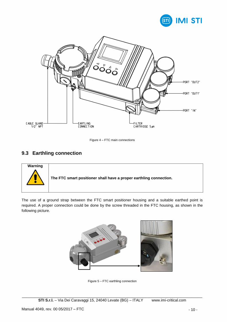
Figure 4 – FTC main connections
9.3 Earthling connection
Warning
The FTC smart positioner shall have a proper earthling connection.
The use of a ground strap between the FTC smart positioner housing and a suitable earthed point is
required. A proper connection could be done by the screw threaded in the FTC housing, as shown in the
following picture.
Figure 5 – FTC earthling connection

_____________________________________________________________________________________ STI S.r.l. – Via Dei Caravaggi 15, 24040 Levate (BG) – ITALY www.imi-critical.com
Manual 4049, rev. 00 05/2017 – FTC - 11 -
9.4 Pneumatic connections
Warning
Check that the values of pneumatic supply available are compatible with those reported on the label of the FTC smart positioner. User must consider and take all precautions to avoid that pressurized parts are not used out of specified range and to avoid exposure to fire.
Important
For easier maintenance, it is recommended to install a filter with five micron cartridge and shut-off valve on the supply connection.
It is recommended to follow these steps:
- the pressure line pipe has to be sized to avoid significant pressure drop during the actuator stroke;
- the piping between FTC smart positioner and actuator has to be ¼” and shorter as possible;
- during piping connection be careful to keep clean the internal side of piping and fittings, free from
threaded sealing material or any other contaminants;
- the FTC smart positioner is suitable for single acting actuators and double acting actuators (with or
without spring):
o for double acting actuators (without spring):
i. Port IN must be connected to the supply line;
ii. Port OUT2 (or M6 thread hole) must be connected to the actuator chamber that has to
vent at signal fail position (no power);
iii. Port OUT1 must be connected to the actuator chamber that has to be pressurized at
signal fail position (no power);
o for double acting actuators (with spring):
i. Port IN must be connected to the supply line;
ii. Port OUT2 (or M6 thread hole) must be connected to the actuator chamber that has to
vent at signal fail position (no power);
iii. Port OUT1 must be connected to the actuator chamber that has to be pressurized at
signal fail position (no power);
o for single acting actuators:
i. Port IN must be connected to the supply line;
ii. Port OUT2 (or M6 thread hole) must be connected to the actuator chamber that has to
vent at signal fail position (no power);
iii. Port OUT1 must be plugged with tight plug suitable for the pressure rating and area
classification;
- no load or bending moment are allowed on pneumatic connection;
- the supply pressure must be lower than actuator design pressure;
- to check the correct mounting of the pneumatic connections, pressurize the FTC smart positioner
without any power signal and check if the actuator moves to the 0% signal position.

_____________________________________________________________________________________ STI S.r.l. – Via Dei Caravaggi 15, 24040 Levate (BG) – ITALY www.imi-critical.com
Manual 4049, rev. 00 05/2017 – FTC - 12 -
9.5 Electrical connection
It is recommended to follow these steps:
- use shielded cables during the installation of the FTC smart positioner;
- observe ESD precautions during the handling of the electrical cables and connections inside the FTC
smart positioner;
- use an earthed wrist strap during the operations;
- the electrical connections must be done according to diagram and label;
- the signal current circuit and the input and output circuitry must meet the explosion protection
requirements stipulated in the certificates;
- close the lids during normal operation.
4-20 mA IN 4-20 mA OUT
L-
L+
AO+
AO-

_____________________________________________________________________________________ STI S.r.l. – Via Dei Caravaggi 15, 24040 Levate (BG) – ITALY www.imi-critical.com
Manual 4049, rev. 00 05/2017 – FTC - 13 -
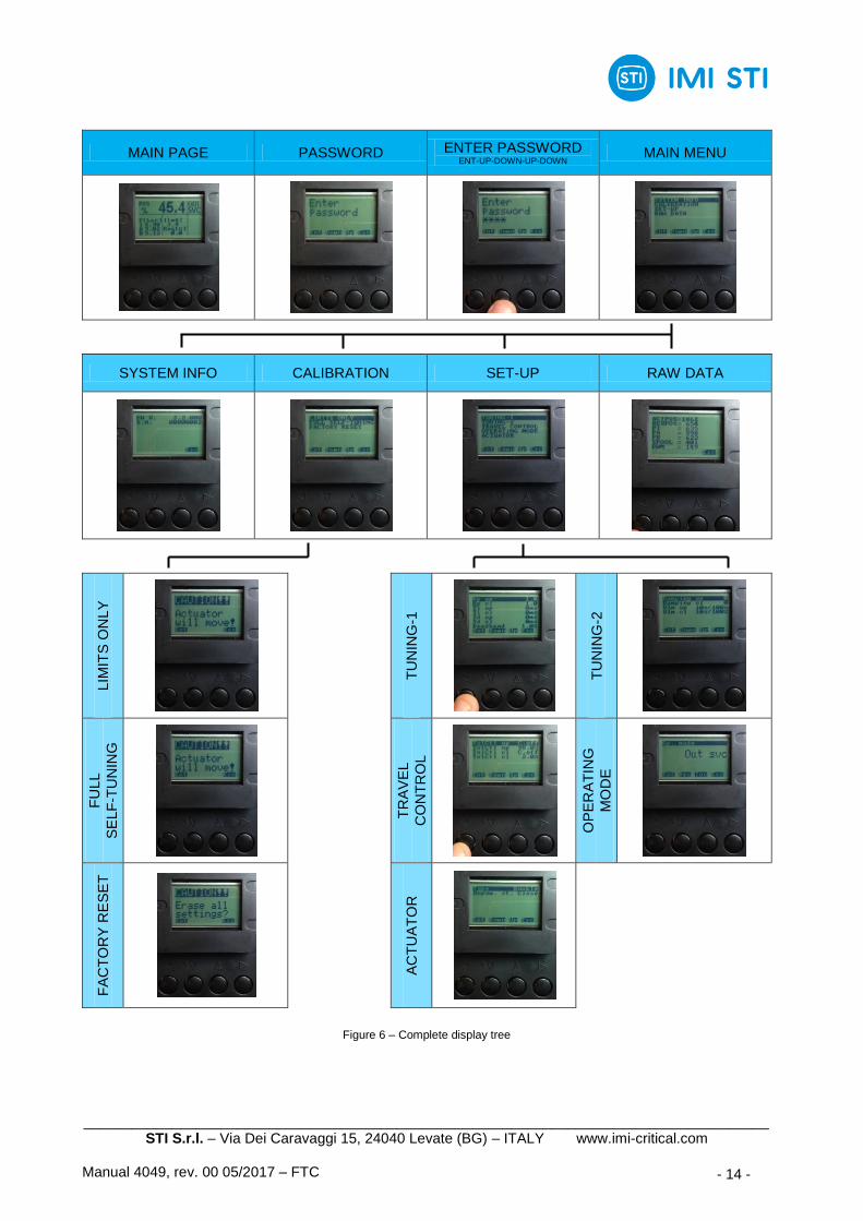
9.6 Self-tuning guide
Warning
The actuator will move during the self tuning.
Follow these steps using the display buttons (ENT, DOWN, UP, ESC):
- turn on the FTC smart positioner;
- push any button and then enter the password (ENT-UP-DOWN-UP-DOWN);
- select set-up from main menu;
- select operating mode menu from set-up menu;
- select “Out svc” in the operating mode menu;
- come back to set-up menu;
- select actuator menu from set-up menu;
- chose the actuator type;
- come back to main menu;
- select calibration menu from main menu;
- select full self-tuning menu from calibration menu;
- start the self-tuning.
_____________________________________________________________________________________ STI S.r.l. – Via Dei Caravaggi 15, 24040 Levate (BG) – ITALY www.imi-critical.com
Manual 4049, rev. 00 05/2017 – FTC - 14 -
MAIN PAGE PASSWORD ENTER PASSWORD ENT-UP-DOWN-UP-DOWN
MAIN MENU
SYSTEM INFO CALIBRATION SET-UP RAW DATA
LIM
ITS
ON
LY
TU
NIN
G-1
TU
NIN
G-2
FU
LL
SE
LF
-TU
NIN
G
TR
AV
EL
CO
NT
RO
L
OP
ER
AT
ING
MO
DE
FA
CT
OR
Y R
ES
ET
AC
TU
AT
OR
Figure 6 – Complete display tree

_____________________________________________________________________________________ STI S.r.l. – Via Dei Caravaggi 15, 24040 Levate (BG) – ITALY www.imi-critical.com
Manual 4049, rev. 00 05/2017 – FTC - 15 -
10 INSTRUCTION FOR THE OPERATORS
Warning
The following instructions must be respected: - operations must be carried out only by skilled operators who have the
required qualification and have read and understood this instruction manual. These operators shall be sufficiently trained and experienced and they shall know the relevant standards and regulations in order to be able to judge their assigned tasks and recognize potential hazards. Only qualified operators who have the required certificates are authorized to work on explosion-protected devices.
- always wear protective clothing, gloves, and eyewear to prevent personal injury. Check with your process or safety engineer for any additional measures that must be taken to protect against process media.
Important
Any repair work other than the operations outlines in this Instruction Manual is allowed only if STI S.r.l. authorises it.
10.1 Field activities
During the start-up of the FTC smart positioner:
- check that the pressure and quality of the supply fluid (filtering degree, dehydration, etcetera) are as
prescribed;
- check if the operating condition are as prescribed;
- check if the FTC is correctly mounted;
- check that there are no leak of the pneumatic connections;
- remove all rust on the FTC surfaces;
- perform a complete functional test of the entire system where the FTC is mounted.
10.2 Residual risks
Reasonably foreseeable misuse:
- risks due to movements of loads during transport and installation;
- installation in ambient with not planned conditions;
- high or very low FTC surface temperatures due to environment or other causes shall be considered as
a possible risk of person injury in case of contact;
- insert incorrect motive fluid into the system;
- supply pressure out the planned range;
- emissions of hazardous substances where dangerous gases are used as motive fluid.
_____________________________________________________________________________________ STI S.r.l. – Via Dei Caravaggi 15, 24040 Levate (BG) – ITALY www.imi-critical.com
Manual 4049, rev. 00 05/2017 – FTC - 16 -
11 MAINTENANCE
Warning
The following instructions must be respected: - operations must be carried out only by skilled operators (STI operators or
operators qualified by STI are recommended); - always wear protective clothing, gloves, and eyewear to prevent personal
injury. Check with your process or safety engineer for any additional measures that must be taken to protect against process media.
Before any type of operation and/or maintenance is performed, make sure that:
- actuator, accessories and all connected equipment are not under pressure and in safe conditions;
- fluid supply, power or other energy sources and signals are disconnected;
11.1 Periodic Inspections and maintenance
Periodic visual inspections are recommended. The user shall:
- plan and provide a periodic cleaning/maintenance program that will maintain the external surface of
the FTC smart positioner free from excessive layer of dust.
11.2 Extraordinary maintenance
In case of extraordinary maintenance proceed as written in Section 12.
_____________________________________________________________________________________ STI S.r.l. – Via Dei Caravaggi 15, 24040 Levate (BG) – ITALY www.imi-critical.com
Manual 4049, rev. 00 05/2017 – FTC - 17 -
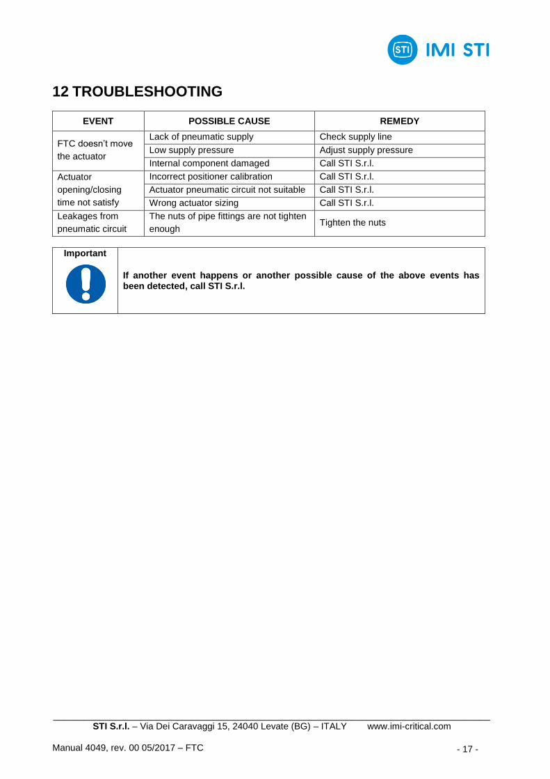
12 TROUBLESHOOTING
EVENT POSSIBLE CAUSE REMEDY
FTC doesn’t move
the actuator
Lack of pneumatic supply Check supply line
Low supply pressure Adjust supply pressure
Internal component damaged Call STI S.r.l.
Actuator
opening/closing
time not satisfy
Incorrect positioner calibration Call STI S.r.l.
Actuator pneumatic circuit not suitable Call STI S.r.l.
Wrong actuator sizing Call STI S.r.l.
Leakages from
pneumatic circuit
The nuts of pipe fittings are not tighten
enough Tighten the nuts
Important
If another event happens or another possible cause of the above events has been detected, call STI S.r.l.
_____________________________________________________________________________________ STI S.r.l. – Via Dei Caravaggi 15, 24040 Levate (BG) – ITALY www.imi-critical.com
Manual 4049, rev. 00 05/2017 – FTC - 18 -
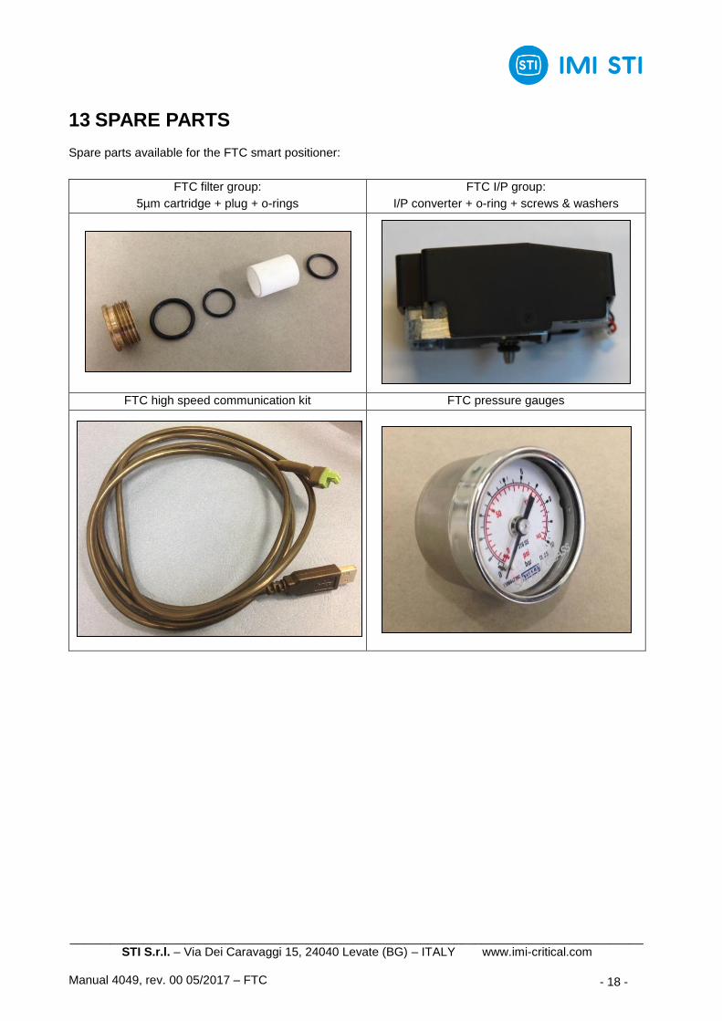
13 SPARE PARTS
Spare parts available for the FTC smart positioner:
FTC filter group:
5µm cartridge + plug + o-rings
FTC I/P group:
I/P converter + o-ring + screws & washers
FTC high speed communication kit FTC pressure gauges

_____________________________________________________________________________________ STI S.r.l. – Via Dei Caravaggi 15, 24040 Levate (BG) – ITALY www.imi-critical.com
Manual 4049, rev. 00 05/2017 – FTC - 19 -
14 DECOMMISSIONING
SUBJECT HAZARDOUS RECYCABLE DISPOSAL
Metals No Yes Use licensed recyclers
Plastics No Yes Use specialist recyclers
Rubber (seals, o-rings) Yes No May require special treatment before disposal, use specialist waste disposal companies
Warning
The following instructions must be respected: - operations must be carried out only by skilled operators; - always wear protective clothing, gloves, and eyewear to prevent personal
injury. Check with your process or safety engineer for any additional measures that must be taken to protect against process media.
Important
Check local authority regulation before disposal.