ftb-8115 transport blazer sonet/sdh test module · ftb-8115 sonet/sdh test module multiplatform...
TRANSCRIPT

SONET/SDH TEST MODULE
FTB-8115Transport Blazer
nETWoRK TESTing — TRAnSPoRT AnD DATAcoM
Fully integrated test solution supporting SonET/SDh test functions
DS0/E0 to OC-48/STM-16 testing in a single module
Supports SONET, SDH, DSn and PDH
SmartMode automatic signal structure discovery with real-time simultaneous monitoring of all discovered STS/AU and user-selected VT/TU channels
Intuitive, feature-rich user interface with available automated test scripting and multi-user remote management capabilities
EXFO Connect-compatible: automated asset management; data goes through the cloud and into a dynamic database
Platform compatibility FTB-200 Compact Platform
FTB-500 Platform
FTB-8115SONET/SDH Test Module
SONET/SDH NE
SONET/SDH NE
SONET/SDH NE
SONET/SDH NE
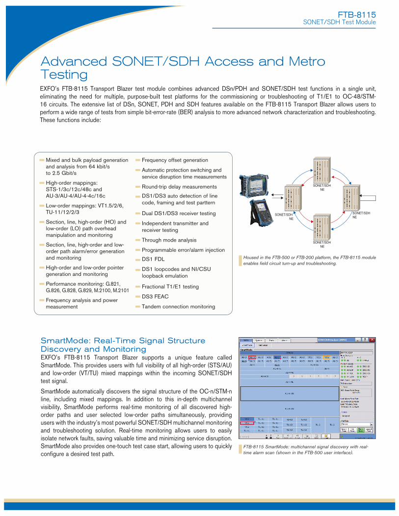
Advanced SONET/SDH Access and Metro TestingEXFO’s FTB-8115 Transport Blazer test module combines advanced DSn/PDH and SONET/SDH test functions in a single unit, eliminating the need for multiple, purpose-built test platforms for the commissioning or troubleshooting of T1/E1 to OC-48/STM-16 circuits. The extensive list of DSn, SONET, PDH and SDH features available on the FTB-8115 Transport Blazer allows users to perform a wide range of tests from simple bit-error-rate (BER) analysis to more advanced network characterization and troubleshooting. These functions include:
Mixed and bulk payload generation and analysis from 64 kbit/s to 2.5 Gbit/s
High-order mappings: STS-1/3c/12c/48c and AU-3/AU-4/AU-4-4c/16c
Low-order mappings: VT1.5/2/6, TU-11/12/2/3
Section, line, high-order (HO) and low-order (LO) path overhead manipulation and monitoring
Section, line, high-order and low-order path alarm/error generation and monitoring
High-order and low-order pointer generation and monitoring
Performance monitoring: G.821, G.826, G.828, G.829, M.2100, M.2101
Frequency analysis and power measurement
Frequency offset generation
Automatic protection switching and service disruption time measurements
Round-trip delay measurements
DS1/DS3 auto detection of line code, framing and test parttern
Dual DS1/DS3 receiver testing
Independent transmitter and receiver testing
Through mode analysis
Programmable error/alarm injection
DS1 FDL
DS1 loopcodes and NI/CSU loopback emulation
Fractional T1/E1 testing
DS3 FEAC
Tandem connection monitoring
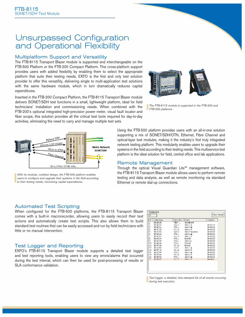
SmartMode: Real-Time Signal Structure Discovery and MonitoringEXFO’s FTB-8115 Transport Blazer supports a unique feature called SmartMode. This provides users with full visibility of all high-order (STS/AU) and low-order (VT/TU) mixed mappings within the incoming SONET/SDH test signal.
SmartMode automatically discovers the signal structure of the OC-n/STM-n line, including mixed mappings. In addition to this in-depth multichannel visibility, SmartMode performs real-time monitoring of all discovered high-order paths and user selected low-order paths simultaneously, providing users with the industry’s most powerful SONET/SDH multichannel monitoring and troubleshooting solution. Real-time monitoring allows users to easily isolate network faults, saving valuable time and minimizing service disruption. SmartMode also provides one-touch test case start, allowing users to quickly configure a desired test path.
Housed in the FTB-500 or FTB-200 platform, the FTB-8115 module enables field circuit turn-up and troubleshooting.
FTB-8115 SmartMode: multichannel signal discovery with real-time alarm scan (shown in the FTB-500 user interface).
FTB-8115SONET/SDH Test Module
Multiplatform Support and VersatilityThe FTB-8115 Transport Blazer module is supported and interchangeable on the FTB-500 Platform or the FTB-200 Compact Platform. This cross-platform support provides users with added fl exibility by enabling them to select the appropriate platform that suits their testing needs. EXFO is the fi rst and only test solution provider to offer this versatility, delivering single to multi-application test solutions with the same hardware module, which in turn dramatically reduces capital expenditures.
Inserted in the FTB-200 Compact Platform, the FTB-8115 Transport Blazer module delivers SONET/SDH test functions in a small, lightweight platform, ideal for fi eld technicians’ installation and commissioning needs. When combined with the FTB-200’s optional integrated high-precision power meter, visual fault locator and fi ber scope, this solution provides all the critical test tools required for day-to-day activities, eliminating the need to carry and manage multiple test sets.
Unsurpassed Confi guration and Operational Flexibility
Using the FTB-500 platform provides users with an all-in-one solution supporting a mix of SONET/SDH/OTN, Ethernet, Fibre Channel and optical-layer test modules, making it the industry’s fi rst truly integrated network testing platform. This modularity enables users to upgrade their systems in the fi eld according to their testing needs. This multiservice test platform is the ideal solution for fi eld, central offi ce and lab applications.
Remote Management Through the optical Visual Guardian Lite™ management software, the FTB-8115 Transport Blazer module allows users to perform remote testing and data analysis, as well as remote monitoring via standard Ethernet or remote dial-up connections.
Automated Test Scripting When confi gured for the FTB-500 platforms, the FTB-8115 Transport Blazer comes with a built-in macrorecorder, allowing users to easily record their test actions and automatically create test scripts. This also allows them to build standard test routines that can be easily accessed and run by fi eld technicians with little or no manual intervention.
Test logger and ReportingEXFO’s FTB-8115 Transport Blazer module supports a detailed test logger and test reporting tools, enabling users to view any errors/alarms that occurred during the test interval, which can then be used for post-processing of results or SLA conformance validation.
The FTB-8115 module is supported in the FTB-200 and FTB-500 platforms.
With its modular, multislot design, the FTB-500 platform enables users to confi gure and upgrade their systems in the fi eld according to their testing needs, minimizing capital expenditures.
Test logger: a detailed, time-stamped list of all events occurring during test execution.
SONET/SDH NE
SONET/SDH NE
SONET/SDH NE
SONET/SDH NE
FTB-8115SONET/SDH Test Module
EXpert Test Tools on the FTB-200 PlatformEXpert Test Tools is a series of platform-based software testing tools that enhance the value of the FTB-200 platform, providing additional testing capabilities without the need for additional modules or units.
AuToMATED ASSET MAnAgEMEnT. PuSh TEST DATA in the cloud. gET connEcTED.
EXFO Connect pushes and stores test equipment and test data content automatically in the cloud, allowing you to streamline test operation from build-out to maintenance.
EXFo connEcT
EXpert VoIP generates a voice-over-IP call directly from the test platform to validate performance during service turn-up and troubleshooting.
• Supports a wide range of signaling protocols, including SIP, SCCP, H.248/Megaco and H.323
• Supports MOS and R-factor quality metrics
• Simplifies testing with configurable pass/fail thresholds and RTP metrics
EXpert IP integrates six commonly used datacom test tools into one platform-based application to ensure that field technicians are prepared for a wide range of testing needs.
• Rapidly performs debugging sequences with VLAN scan and LAN discovery
• Validates end-to-end ping and traceroute
• Verifies FTP performance and HTTP availability
This powerful IPTV quality assessment solution enables set-top-box emulation and passive monitoring of IPTV streams, allowing quick and easy pass/fail verification of IPTV installations.
• Real-time video preview
• Analyzes up to 10 video streams
• Comprehensive QoS and QoE metrics including MOS score
EXpert TEST ToolS

FTB-8115SONET/SDH Test Module
Electrical InterfacesThe following section provides detailed information on all supported electrical interfaces.
DS1 E1/2M E2/8M E3/34M DS3/45M STS-1e/STM-0e/52M E4/140M STS-3e/STM-1e/155M
Tx Pulse Amplitude 2.4 to 3.6 V 3.0 V 2.37 V 2.37 V 1.0 ± 0.1 V 0.36 to 0.85 V 1.0 ± 0.1 Vpp 0.5 V
Tx Pulse Mask GR-499 G.703 G.703 G.703 G.703 GR-253 G.703 Figure 9.5 Figure 15 Figure 15 Figure 16 Figure 17 Figure 4-10/4-11 Figure 18/19
Tx LBO Preamplification Power dBdsx +0.6 dBdsx (0-133 ft) 0 to 225 ft 0 to 225 ft +1.2 dBdsx (133-266 ft) 225 to 450 ft 225 to 450 ft 0 to 225 ft +1.8 dBdsx (266-399 ft) +2.4 dBdsx (399-533 ft) +3.0 dBdsx (533-655 ft)
Cable Simulation Power dBdsx –22.5 dBdsx 450 to 900 (927) ft 450 to 900 (927) ft –15.0 dBdsx –7.5 dBdsx 0 dBdsx
Rx Level Sensitivity For 772 kHz: For 1024 kHz: For 1024 kHz: For 4224 kHz: For 17.184 MHz: For 22.368 MHz: For 25.92 MHz: For 70 MHz: For 78 MHz: TERM: ≤ 26 dB (cable TERM: ≤ 6 dB TERM: ≤ 6 dB TERM: ≤ 6 dB TERM: ≤ 12 dB TERM: ≤ 10 dB TERM: ≤ 10 dB TERM: ≤ 12 dB TERM: ≤ 12.7 dB loss only) at 0 dBdsx Tx (cable loss only) (cable loss only) (cable loss only) (coaxial cable loss only) (cable loss only) (cable loss only) (coaxial cable loss only) (coaxial cable loss only) DSX-MON: ≤ 26 dB MON: ≤ 25 dB MON: ≤ 26 dB MON: ≤ 26 dB MON: ≤ 26 dB DSX-MON: ≤ 26.5 dB MON: ≤ 25 dB MON: ≤ 26 dB MON: ≤ 26 dB (20 dB resistive loss + (20 dB resistive loss (20 dB resistive loss + (20 dB resistive loss + (20 dB resistive loss + (21.5 dB resistive loss (20 dB resistive loss (20 dB resistive loss (20 dB resistive loss cable loss ≤ 6 dB) + cable loss ≤ 6 dB) cable loss ≤ 6 dB) cable loss ≤ 6 dB) cable loss ≤ 6 dB) + cable loss ≤ 5 dB) + cable loss ≤ 5 dB) + cable loss ≤ 6 dB) + cable loss ≤ 6 dB) Bridge: ≤ 6 dB Bridge: ≤ 6 dB Bridge: ≤ 6 dB (cable loss only) (cable loss only) (cable loss only) Note: measurement units = dBdsx Note: measurement units = dBm Note: measurement units = dBm Note: measurement units = dBm Note: measurement units = dBm Note: measurement units = dBm Note: measurement units = dBm Note: measurement units = dBm Note: measurement units = dBm
Transmit Bit Rate 1.544 Mbit/s ± 4.6 ppm 2.048 Mbit/s ± 4.6 ppm 2.048 Mbit/s ± 4.6 ppm 8.448 Mbit/s ± 4.6 ppm 34.368 Mbit/s ± 4.6 ppm 44.736 Mbit/s ± 4.6 ppm 51.84 Mbit/s ± 4.6 ppm 139.264 Mbit/s ±4.6 ppm 155.52 Mbit/s ± 4.6 ppm
Receive Bit Rate 1.544 Mbit/s ± 140 ppm 2.048 Mbit/s ± 100ppm 2.048 Mbit/s ± 100ppm 8.448 Mbit/s ± 100 ppm 34.368 Mbit/s ± 100 ppm 44.736 Mbit/s ± 100 ppm 51.84 Mbit/s ± 100 ppm 139.264 Mbit/s ± 100 ppm 155.52 Mbit/s ± 100 ppm
Measurement Accuracy Frequency (ppm) ± 4.6 ±4.6 ±4.6 ± 4.6 ± 4.6 ±4.6 ±4.6 ±4.6 ±4.6(uncertainty)
Electrical Power DSX range: ± 1.0 NORMAL: ± 1.0 NORMAL: ± 1.0 NORMAL: ± 1.0 NORMAL: ±1.0 DSX range: ± 1.0 DSX range: ± 1.0 NORMAL: ±1.0 NORMAL: ± 1.0 (dB) DSX-MON range: ± 2.0 MONITOR: ± 2.0 MONITOR: ± 2.0 MONITOR: ± 2.0 MONITOR: ±2.0 DSX-MON range: ±2.0 DSX-MON range: ±2.0 MONITOR: ±2.0 MONITOR: ±2.0
Peak-to-Peak Voltage ±10 % down to 500 mVpp ±10% down to 500 mVpp ±10% down to 500 mVpp ±10% down to 400 mVpp ±10% down to 200 mVpp ±10% down to 200 mVpp ±10% down to 200 mVpp ±10% down to 200 mVpp ±10% down to 200 mVpp
Frequency Offset Generation 1.544 Mbit/s ± 140 ppm 2.048 Mbit/s ± 70 ppm 2.048 Mbit/s ± 70 ppm 8.448 Mbit/s ± 50 ppm 34.368 Mbit/s ± 50 ppm 44.736 Mbit/s ± 50 ppm 51.84 Mbit/s ± 50 ppm 139.264 Mbit/s ± 50 ppm 155.52 Mbit/s ± 50 ppm
Intrinsic Jitter (Tx) ANSI T1.403 section 6.3 G.823 section 5.1 G.823 section 5.1 G.823 section 5.1 G.823 section 5.1 GR-449 section 7.3 GR-253 section G.823 section 5.1 G.825 section 5.1 GR-499 section 7.3 G.751 section 2.3 (categories I and II) 5.6.2.2 (category II) GR-253 section 5.6.2.2
Input Jitter Tolerance AT&T PUB 62411 G.823 section 7.1 G.823 section 7.1 G.823 section 7.1 G.823 section 7.1 GR-449 section 7.3 GR-253 section 5.6.2.2 G.823 section 7.1 G.825 section 5.2 GR-499 section 7.3 (categories I and II) (category II) G.751 section 3.3 GR-253 section 5.6.2.3
Line Coding AMI and B8ZS AMI and HDB3 AMI and HDB3 HDB3 HDB3 B3ZS B3ZS CMI CMI
Input Impedance 100 ohms ± 5%, balanced 120 ohms ± 5%, balanced 75 ohms ± 5%, unbalanced 75 ohms ± 5%, unbalanced 75 ohms ± 5%, unbalanced 75 ohms ± 5%, unbalanced 75 ohms ± 5%, unbalanced 75 ohms ± 10%, unbalanced 75 ohms ± 5%, unbalanced (Resistive Termination)
Connector Type BANTAM and RJ-48C BANTAM and RJ-48C BNC BNC BNC BNC BNC BNC BNC
STS-3eGR-253Figure 4-12, 4-13, 4-14
STM-1e/155MG.703Figure 4-14/22, 23
45MG.703Figure 14
DS-3GR-499Figure 9-8
SynchRonizATion inTERFAcES
External Clock DS1/1.5M External Clock E1/2M External Clock E1/2M 2 MHz
Tx Pulse Amplitude 2.4 to 3.6 V 3.0 V 2.37 V 0.75 to 1.5 V
Tx Pulse Mask GR-499 figure 9.5 G.703 figure 15 G.703 figure 15 G.703 figure 20
Typical power dBdsx +0.6 dBdsx (0-133 ft) Tx LBO Preamplification +1.2 dBdsx (133-266 ft) +1.8 dBdsx (266-399 ft) +2.4 dBdsx (399-533 ft) +3.0 dBdsx (533-655 ft)
Rx Level Sensivity TERM: ≤ 6 dB (cable loss only) (at 772 kHz for T1) TERM: = ≤ 6 dB (cable loss only) TERM: = ≤ 6 dB (cable loss only) DSX-MON: ≤ 26 dB (20 dB resistive loss + cable loss ≤ 6 dB) MON: ≤ 26 dB (20 dB resistive loss + cable loss ≤ 6 dB) MON: ≤ 26 dB (resistive loss + cable loss ≤ 6 dB) ≤ 6 dB (cable loss only) Bridge: ≤ 6 dB (cable loss only) Bridge: ≤ 6 dB (cable loss only) Bridge: ≤ 6 dB (cable loss only)
Transmission Bit Rate 1.544 Mbit/s ± 4.6 ppm 2.048 Mbit/s ± 4.6 ppm 2.048 Mbit/s ± 4.6 ppm
Reception Bit Rate 1.544 Mbit/s ± 50 ppm 2.048 Mbit/s ± 50 ppm 2.048 Mbit/s ± 50 ppm
Intrinsic Jitter (Tx) ANSI T1.403 section 6.3 G.823 G.823 G.703
GR-499 section 7.3 section 6.1 section 6.1 table 11
Input Jitter AT&T PUB 62411 G.823 section 7.2 G.823 section 7.2
Tolerance GR-499 SECTION 7.3 G.813 G.813
Line Coding AMI and B8ZS AMI and HDB3 AMI and HDB3
Input Impedance 75 ohms ± 5%, unbalanced 75 ohms ± 5%, unbalanced 75 ohms ± 5%, unbalanced 75 ohms ± 5%, unbalanced (Resistive Termination)
Connector Type BNC a BNC a BNC BNC
Note
a. Adaptation cable required for BANTAM.
FTB-8115SONET/SDH Test Module
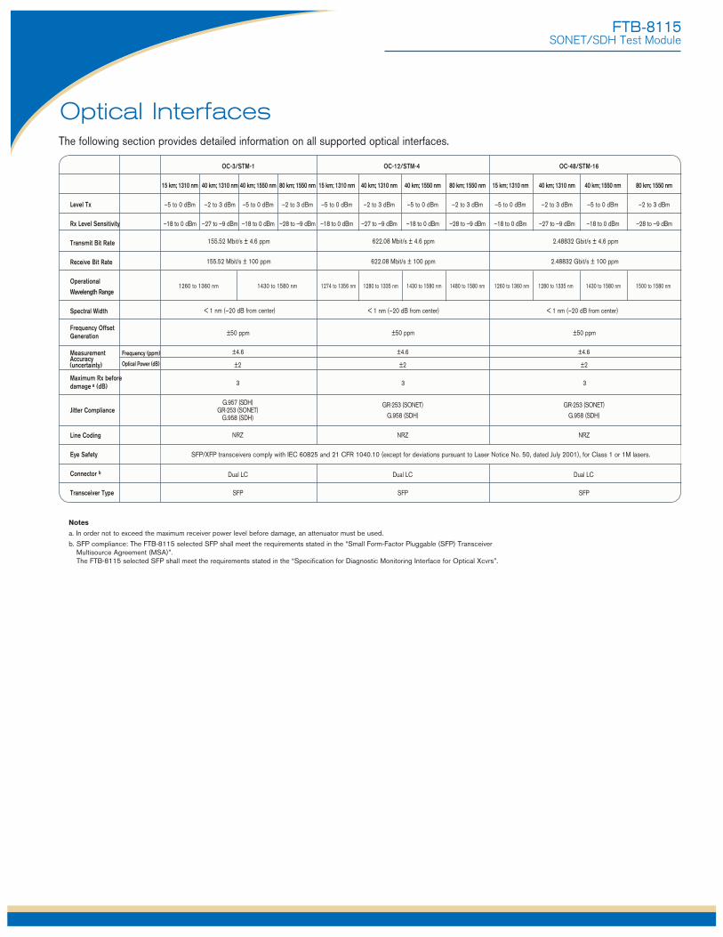
Optical InterfacesThe following section provides detailed information on all supported optical interfaces.
Notes
a. In order not to exceed the maximum receiver power level before damage, an attenuator must be used.
b. SFP compliance: The FTB-8115 selected SFP shall meet the requirements stated in the “Small Form-Factor Pluggable (SFP) Transceiver Multisource Agreement (MSA)”. The FTB-8115 selected SFP shall meet the requirements stated in the “Specification for Diagnostic Monitoring Interface for Optical Xcvrs”.
155.52 Mbit/s ± 4.6 ppm 622.08 Mbit/s ± 4.6 ppm 2.48832 Gbit/s ± 4.6 ppm
2.48832 Gbit/s ± 100 ppm622.08 Mbit/s ± 100 ppm155.52 Mbit/s ± 100 ppm
1260 to 1360 nm 1430 to 1580 nm 1430 to 1580 nm 1480 to 1580 nm1274 to 1356 nm 1280 to 1335 nm 1430 to 1580 nm 1500 to 1580 nm1260 to 1360 nm 1280 to 1335 nm
< 1 nm (–20 dB from center) < 1 nm (–20 dB from center) < 1 nm (–20 dB from center)
±50 ppm ±50 ppm ±50 ppm
±4.6 ±4.6 ±4.6
±2 ±2 ±2
3 3 3
G.957 (SDH) GR-253 (SONET)
G.958 (SDH)
GR-253 (SONET)
G.958 (SDH)
GR-253 (SONET)
G.958 (SDH)
NRZ NRZ NRZ
Dual LC Dual LC Dual LC
SFP SFP SFP
(uncertainty)
OC-3/STM-1 OC-12/STM-4 OC-48/STM-16
15 km; 1310 nm 40 km; 1310 nm 40 km; 1550 nm 80 km; 1550 nm 15 km; 1310 nm 40 km; 1310 nm 40 km; 1550 nm 80 km; 1550 nm 15 km; 1310 nm 40 km; 1310 nm 40 km; 1550 nm 80 km; 1550 nm
Level Tx –5 to 0 dBm –2 to 3 dBm –5 to 0 dBm –2 to 3 dBm –5 to 0 dBm –2 to 3 dBm –5 to 0 dBm –2 to 3 dBm –5 to 0 dBm –2 to 3 dBm –5 to 0 dBm –2 to 3 dBm
Rx Level Sensitivity –18 to 0 dBm –27 to –9 dBm –18 to 0 dBm –28 to –9 dBm –18 to 0 dBm –27 to –9 dBm –18 to 0 dBm –28 to –9 dBm –18 to 0 dBm –27 to –9 dBm –18 to 0 dBm –28 to –9 dBm
Transmit Bit Rate
Receive Bit Rate
Operational
Wavelength Range
Spectral Width
Frequency Offset Generation
Measurement Frequency (ppm) Accuracy Optical Power (dB)
Maximum Rx before damage a (dB)
Jitter Compliance
Line Coding
Eye Safety SFP/XFP transceivers comply with IEC 60825 and 21 CFR 1040.10 (except for deviations pursuant to Laser Notice No. 50, dated July 2001), for Class 1 or 1M lasers.
Connector b
Transceiver Type
FTB-8115SONET/SDH Test Module
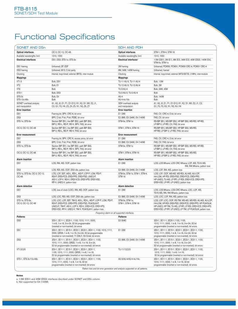
SonET AnD DSn SDh AnD PDhOptical interfaces OC-3, OC-12, OC-48 Optical interfaces STM-1, STM-4, STM-16Available wavelengths (nm) 1310, 1550 Available wavelengths (nm) 1310, 1550Electrical interfaces DS1, DS3, STS-1e, STS-3e Electrical interfacesa 1.5M (DS1), 2M (E1), 8M (E2), 34M (E3), 45M (DS3), 140M (E4),
STM-0e, STM-1eDS1 framing Unframed, SF, ESF 2M framing Unframed, PCM30, PCM31, PCM30 CRC-4, PCM31 CRC-4DS3 framing Unframed, M13, C-bit parity 8M, 34M, 140M framing Unframed, framedClocking Internal, loop-timed, external (BITS), inter-module Clocking Internal, loop-timed, external (MTS/SETS), 2 MHz, inter-moduleMappings Mappings
VT1.5 Bulk, DS1 TU-11-AU-3, TU-11-AU-4 Bulk, 1.5M VT2 Bulk, E1 TU-12-AU-3, TU-12-AU-4 Bulk, 2M VT6 Bulk TU-3-AU-4 Bulk, 34M, 45M STS-1 Bulk, DS3 TU-2-AU-3, TU-2-AU-4 Bulk STS-3c Bulk, E4 AU-4 Bulk, 140M STS-12c/48c Bulk AU-4-4c/16c Bulk SONET overhead analysis A1, A2, J0, E1, F1, D1-D12, K1, K2, S1, M0, E2, J1, SDH overhead analysis A1, A2, J0, E1, F1, D1-D12, K1, K2, S1, M0, E2, J1, C2, and manipulation C2, G1, F2, H4, Z3, Z4, Z5, N1, N2, Z6, Z7 and manipulation G1, F2, F3, K3, N1, N2, K4, H4Error insertion Error insertion
DS1 Framing bit, BPV, CRC-6, bit error E1 (2M) FAS, CV, CRC-4, E-bit, bit errorDS3 BPV, C-bit, F-bit, P-bit, FEBE, bit error E2 (8M), E3 (34M), E4 (140M) FAS, CV, bit errorSTS-1e, STS-3e Section BIP (B1), line BIP (B2), path BIP (B3), STM-0e, STM-1e RS-BIP (B1), MS-BIP (B2), HP-BIP (B3), MS-REI, HP-REI, BIP-2, REI-L, REI-P, REI-V, BPV, FAS, bit error LP-BIP-2, LP-REI, CV, FAS, bit errorOC-3, OC-12, OC-48 Section BIP (B1), line BIP (B2), path BIP (B3), STM-1, STM-4, STM-16 RS-BIP (B1), MS-BIP (B2), HP-BIP (B3), MS-REI, BIP-2, REI-L, REI-P, REI-V, FAS, bit error HP-REI, LP-BIP-2, LP-REI, FAS, bit errorError measurement Error measurement
DS1 Framing bit, BPV, CRC-6, excess zeros, bit error E1 (2M) FAS, CV, CRC-4, E-bit, bit errorDS3 BPV, C-bit, F-bit, P-bit, FEBE, bit error E2 (8M), E3 (34M), E4 (140M) FAS, CV, FAS, bit errorSTS-1e, STS-3e Section BIP (B1), line BIP (B2), path BIP (B3), STM-0e, STM-1e RS-BIP (B1), MS-BIP (B2), HP-BIP (B3), MS-REI, HP-REI, BIP-2, REI-L, REI-P, REI-V, BPV, FAS, bit error LP-BIP-2, LP-REI, CV, FAS, bit errorOC-3, OC-12, OC-48 Section BIP (B1), line BIP (B2), path BIP (B3), STM-1, STM-4, STM-16 RS-BIP (B1), MS-BIP (B2), HP-BIP (B3), MS-REI, BIP-2, REI-L, REI-P, REI-V, FAS, bit error HP-REI, LP-BIP-2, LP-REI, FAS, bit errorAlarm insertion Alarm insertion
DS1 LOS, RAI, AIS, OOF, pattern loss E1 (2M) LOS, LOS Mframe, LOS CRC Mframe, LOF, AIS, TS16 AIS, RAI, RAI Mframe, pattern loss
DS3 LOS, RDI, AIS, OOF, DS3 idle, pattern loss E2 (8M), E3 (34M), E4 (140M) LOS, LOF, RAI, AIS, pattern lossSTS-1e, STS-3e, OC-3, OC-12, LOS, LOF, SEF, AIS-L, RDI-L, AIS-P, LOP-P, LOM, PDI-P, STM-0e, STM-1e, STM-1, STM-4, LOS, LOF, OOF, MS-AIS, MS-RDI, AU-AIS, AU-LOP, OC-48 RDI-P, ERDI-PCD, ERDI-PPD, ERDI-PSD, UNEQ-P, STM-16 H4-LOM, HP-PDI, ERDI-PSD, ERDI-PCD, ERDI-PPD, AIS-V, LOP-V, RDI-V, ERDI-VCD, ERDI-VPD, ERDI-VSD, HP-UNEQ, TU-AIS, LP-RFI, LP-RDI, ERDI-VCD, ERDI-VPD, RFI-V, UNEQ-V, pattern loss ERDI-VSD, LP-RFI, LP-UNEQ, pattern lossAlarm detection Alarm detection
DS1 LOS, loss of clock (LOC), RAI, AIS, OOF, pattern loss E1 (2M) LOS, LOS Mframe, LOS CRC Mframe, LOC, LOF, AIS, TS16 AIS, RAI, RAI Mframe, pattern loss
DS3 LOS, LOC, RDI, AIS, OOF, DS3 idle, pattern loss E2 (8M), E3 (34M), E4 (140M) LOS, LOC, LOF, RAI, AIS, pattern lossSTS-1e, STS-3e, LOS, LOC, LOF, SEF, TIM-S, AIS-L, RDI-L, AIS-P, LOP-P, LOM, PDI-P, STM-0e, STM-1e, LOS, LOF, LOC, OOF, RS-TIM, MS-AIS, MS-RDI, AU-AIS, AU-LOP, OC-3, OC-12, OC-48 RDI-P, ERDI-PCD, ERDI-PPD, ERDI-PSD, PLM/SLM-P, STM-1, STM-4, STM-16 H4-LOM, HP-RDI, ERDI-PSD, ERDI-PCD, ERDI-PPD, HP-PLM/SLM, UNEQ-P, TIM-P, AIS-V, LOP-V, RDI-V, ERDI-VCD, ERDI-VPD, HP-UNEQ, HP-TIM, TU-AIS, LP-RFI, LP-RDI, ERDI-VCD, ERDI-VPD, ERDI-VSD, RFI-V, UNEQ-V, TIM-V, PLM/SLM-V, pattern loss ERDI-VSD, LP-RFI, LP-UNEQ, LP-TIM, LP-PLM/SLM, pattern loss
Frequency alarm on all supported interfaces.Patterns Patterns
DS0 2E9-1, 2E11-1, 2E20-1, 1100, 1010, 1111, 0000, E0 (64K) 2E9-1, 2E11-1, 2E20-1,1100, 1100, 1-in-8, 1-in-16, 3-in-24, 32 bit programmable 1010, 1111, 0000, 1-in-8, 1-in-16, 3-in-24, 32 bit (inverted or non-inverted), bit errors programmable (inverted or non-inverted), bit errorsDS1 2E9-1, 2E11-1, 2E15-1, 2E20-1, 2E23-1, 2E31-1, 1100, 1010, 1111, E1 (2M) 2E9-1, 2E11-1, 2E15-1, 2E20-1, 2E23-1, 2E31-1, 1100, 0000, QRSS, 1-in-8, 1-in-16, 3-in-24, 32 bit programmable 1010, 1111, 0000, 1-in-8, 1-in-16, 3-in-24, 32 bit (inverted or non-inverted), T1-DALY, 55-Octet, bit errors programmable (inverted or non-inverted), bit errorsDS3 2E9-1, 2E11-1, 2E15-1, 2E20-1, 2E23-1, 2E31-1, 1100, E2 (8M), E3 (34M), E4 (140M) 2E9-1, 2E11-1, 2E15-1, 2E20-1, 2E23-1, 2E31-1, 1100, 1010, 1111, 0000, QRSS, 1-in-8, 1-in-16, 3-in-24, 1010, 1111, 0000, 1-in-8, 1-in-16, 3-in-24b, 32 bit programmable (inverted or non-inverted), bit errors 32 bit programmable (inverted or non-inverted), bit errorsVT1.5/2/6 2E9-1, 2E11-1, 2E15-1, 2E20-1, 2E23-1, 2E31-1, TU-11/12/2/3 2E9-1, 2E11-1, 2E15-1, 2E20-1, 2E23-1, 2E31-1, 1100, 1100, 1010, 1111, 0000, QRSS, 1-in-8, 1-in-16, 1010, 1111, 0000, 1-in-8, 1-in-16, 32 bit programmable (inverted or non-inverted), bit errors 32 bit programmable (inverted or non-inverted), bit errorsSTS-1, STS-3c/12c/48c 2E9-1, 2E11-1, 2E15-1, 2E20-1, 2E23-1, 2E31-1, 1100, AU-3/AU-4/AU-4-4c/16c 2E9-1, 2E11-1, 2E15-1, 2E20-1, 2E23-1, 2E31-1, 1100, 1010, 1111, 0000, 1-in-8, 1-in-16, 32 bit 1010, 1111, 0000, 1-in-8, 1-in-16, 32 bit programmable (inverted or non-inverted), bit errors programmable (inverted or non-inverted), bit errors
Pattern loss and bit error generation and analysis supported on all patterns.
Notes
a. 1.5M (DS1) and 45M (DS3) interfaces discribed under SONET and DSn column. b. Not supported for E4 (140M).
Functional Specifications
FTB-8115SONET/SDH Test Module
ADDiTionAl TEST AnD MEASuREMEnT FuncTionS
Power measurements Supports power measurements, displayed in dBm (dBdsx for DS1), for optical and electrical interfaces.Frequency measurements Supports clock frequency measurements (i.e., received frequency and deviation of the input signal clock from nominal frequency), displayed
in ppm and b/s (bps), for optical and electrical interfaces.Frequency offset generation Supports offsetting the clock of the transmitted signal on a selected interface to exercise clock recovery circuitry on network elements. Dual DSn receivers Supports two DS1 or DS3 receivers, allowing users to simultaneously monitor two directions of a circuit under test in parallel, resulting in
quick isolation of the source of errors.Performance monitoringThe following ITU-T recommendations, and corresponding performance monitoring parameters, are supported on the FTB-8115.
ITU-T recommendation Performance monitoring statistics G.821 ES, EFS, EC, SES, UAS, ESR, SESR, DM G.826 ES, EFS, EB, SES, BBE, UAS, ERS, SESR, BBER G.828 ES, EFS, EB, SES, BBE, SEP, UAS, ESR, SESR, BBER, SEPI G.829 ES, EFS, EB, SES, BBE, UAS, ESR, SESR, BBER M.2100 ES, SES, UAS, ESR, SESR M.2101 ES, SES, BBE, UAS, ESR, SESR, BBERPointer adjustment and analysisGeneration and analysis of HO/AU and LO/TU pointer adjustments as per GR-253, and ITU-T G.703Generation • Pointer increment and decrement • Pointer jump with or without NDF • Pointer value
Programmable error/alarm injection Ability to inject errors/alarms in the following modes: Manual, Constant Rate, Burst, Periodic Burst and Continuous Service disruption time (SDT) measurements The service disruption time test tool measures the time during which there is a disruption of service due to the network switching
from the active channels to the backup channels. User-selectable triggers: All supported alarms and errors. Measurements: last disruption, shortest disruption, longest disruption, average disruption, total disruption, and service disruption count.Round-trip delay (RTD) measurements The round-trip delay test tool measures the time required for a bit to travel from the FTB-8115 transmitter back to its receiver after
crossing a far-end loopback. Measurements are supported on all supported FTB-8115 interfaces and mappings. Measurements: last RTD time, minimum, maximum, average, measurement count (no. of successful RTD tests), failed measurement count.APS message control and monitoring Ability to monitor and set up automatic protection switching messages (K1/K2 byte of SONET/SDH overhead).Synchronization status Ability to monitor and set up synchronization status messages (S1 byte of SONET/SDH overhead). Signal label control and monitoring Ability to monitor and set up payload signal labels (C2, V5 byte of SONET/SDH overhead).Through mode Ability to perform Through mode analysis of any incoming electrical (DSn, PDH) and optical line (OC-3/12/48, STM-1/4/16).M13 mux/demux Ability to multiplex/demultiplex a DS1 signal into/from a DS3 signal. (Note: E1 to DS3 mux/demux available with G.747 software option.)DS1 FDL Support for DS1 Facility Data Link testing. DS1 loopcodes Support for generation of DS1 in-band loopcodes with the availability of up to 10 pairs of user-defined loopcodes.NI/CSU loopback emulation Ability to respond to DS1 in-band/out-of-band loopcodes DS3 FEAC Support for DS3 far-end alarms and loopback codewords.DS1/DS3 auto detection Ability to automatically detect DS1/DS3 line coding, framing and test pattern.Tandem connection monitoring (TCM)a Tandem connection monitoring (TCM), option 2b, is used to monitor the performance of a subsection of a SONET/SDH path routed
via different network providers. The FTB-8115 supports transmitting and receiving alarms and errors on a TCM link; also, transmission and monitoring of the tandem connection (TC) trace can be generated to verify the connection between TCM equipment.
Error generation: TC-IEC, TC-BIP, TC-REI, OEI Error analysis: TC-IEC, TC-REI, OEI, TC-VIOL Alarm generation: TC-RDI, TC-UNEQ, ODI, TC-LTC, TC-IAIS Alarm analysis: TC-TIM, TC-RDI, TC-UNEQ, ODI, TC-LTC, TC-IAIS
Notes
a. HOP and LOP supported.
b. G.707 option 2.
ADDiTionAl FEATuRES
Scripting The built-in scripting engine and embedded macro-recorder provide a simple means of automating test cases and routines. Embedded scripting routines provide a powerful means of creating advanced test scripts. Available for the FTB-500 platform.
Reports Supports generation of test reports in .html, .csv, .txt, .pdf formats. Contents or reports are customizable by the user.Power-up and restore In the event of a power failure to the unit, the active test configuration and test logger are saved and restored upon bootup.Store and load configurations Ability to store and load test configurations to/from non-volatile memory.Alarm hierarchy Alarms are displayed according to a hierarchy based on root cause. Secondary effects are not displayed. This hierarchy serves to facilitate
alarm analysis.Configurable test views This allows users to customize their test views; i.e., to dynamically insert or remove test tabs/windows, in addition to creating new test
windows, so as to accurately match their testing needs.Configurable test timer Provides the ability for a user to set pre-defined test start and stop times.Remote control Remote management software. This allows users to remotely monitor and control the FTB-8115 module via standard Ethernet connection.
Analysis • Pointer increments • Pointer decrements • Pointer jumps (NDF, no NDF) • Pointer value and cumulative offset
FTB-8115SONET/SDH Test Module
2008
EXFO is certified ISO 9001 and attests to the quality of these products. This device complies with Part 15 of the FCC Rules. Operation is subject to the following two conditions: (1) this device may not cause harmful interference, and (2) this device must accept any interference received, including interference that may cause undesired operation. EXFO has made every effort to ensure that the information contained in this specification sheet is accurate. However, we accept no responsibility for any errors or omissions, and we reserve the right to modify design, characteristics and products at any time without obligation. Units of measurement in this document conform to SI standards and practices. In addition, all of EXFO’s manufactured products are compliant with the European Union’s WEEE directive. For more information, please visit www.EXFO.com/recycle. Contact EXFO for prices and availability or to obtain the phone number of your local EXFO distributor.
For the most recent version of this spec sheet, please go to the EXFO website at http://www.EXFO.com/specs
In case of discrepancy, the Web version takes precedence over any printed literature.
EXFO Corporate Headquarters > 400 Godin Avenue, Quebec City (Quebec) G1M 2K2 CANADA | Tel.: +1 418 683-0211 | Fax: +1 418 683-2170 | [email protected]
Toll-free: +1 800 663-3936 (USA and Canada) | www.EXFO.com
EXFO America 3400 Waterview Parkway, Suite 100 Richardson, TX 75080 USA Tel.: +1 972 761-9271 Fax: +1 972 761-9067 EXFO Asia 100 Beach Road, #22-01/03 Shaw Tower SINGAPORE 189702 Tel.: +65 6333 8241 Fax: +65 6333 8242EXFO China 36 North, 3rd Ring Road East, Dongcheng District Beijing 100013 P. R. CHINA Tel.: + 86 10 5825 7755 Fax: +86 10 5825 7722 Room 1207, Tower C, Global Trade CenterEXFO Europe Omega Enterprise Park, Electron Way Chandlers Ford, Hampshire S053 4SE ENGLAND Tel.: +44 23 8024 6810 Fax: +44 23 8024 6801EXFO Finland Elektroniikkatie 2 FI-90590 Oulu, FINLAND Tel.: +358 (0)403 010 300 Fax: +358 (0)8 564 5203EXFO Service Assurance 270 Billerica Road Chelmsford, MA 01824 USA Tel.: +1 978 367-5600 Fax: +1 978 367-5700
SPFTB8115.8AN © 2012 EXFO Electro-Optical Engineering Inc. All rights reserved. Printed in Canada 12/02
ORDERING INFORMATION
gEnERAl SPEciFicATionS
Model
Test optionsSONET = SONET-BASE-SWSDH = SDH-BASE-SWSONET-SDH = Option for combined
SONET/SDH functionality
FTB-8115-XX-XX-XX-XX
SPEciFicATionS
Rate options a
155 = 155 Mbit/s (OC-3/STM-1) c622 = 622 Mbit/s (OC-12/STM-4)2.5G = 2.5 Gbit/s (OC-48/STM-16)
FTB-8115Weight (without transceiver) 0.9 kg (2.0 lb)Size (H x W x D) 96 mm x 51 mm x 288 mm (3 3/4 in x 2 in x 11 3/8 in)Temperature operating 0 °C to 40 °C (32 °F to 104 °F) storage –40 °C to 60 °C (–40 °F to 140 °F)
Example:FTB-8115-SONET-155-622-8194-DUAL-RX
FTB-8080 Sync AnalyzerThe FTB-8080 Synch Analyzer is a comprehensive test solution for telecom network synchronization assurance, monitoring and troubleshooting applications. It offers a full range of wander and sync testing functionalities, including graphical display of TIE, MTIE and TDEV parameters, as well as comparison to ITU/ANSI/TS standards and user-definable masks. The companion Sync View software suite allows remote data retrieval and test case setup, eliminating the need to visit test sites during prolonged monitoring periods. The FTB-8080 can be used in conjunction with the FTB-8105, FTB-8115 and/or FTB-8120/8130 modules to provide wander measurements up to OC-192/STM-64 rates.
For more information on the FTB-8080, please refer to its detailed product specification sheet at http://documents.EXFO.com/specsheets/FTB-8080-ang.pdf
FTB-8120/8130 Transport Blazer Next-Generation SONET/SDH Test ModulesThe FTB-8120 (2.5/2.7 Gbit/s) and FTB-8130 (10/10.7 Gbit/s) Transport Blazer test modules combine advanced DSn/PDH, SONET/SDH, next-generation SONET/SDH and optical transport network (OTN) test functions, eliminating the need for multiple purpose-built test platforms when commissioning or troubleshooting SONET/SDH, OTN and new data-aware SONET/SDH circuits. These modules offer DS0/E0 to OC-192/STM-64 testing in a single unit, and they perform Ethernet-over-SONET/SDH (EoS) testing via optional support for GFP, VCAT and LCAS. Thanks to the SmartMode functionality, they also enable signal structure discovery for rates of up to 10 Gbit/s, with simultaneous monitoring of all discovered STS/AU and user selected VT/TU channels.
For details on the FTB-8120/8130 modules, please refer to the detailed product specification sheet at http://documents.EXFO.com/specsheets/FTB-8120-8130-ang.pdf
complementary Products
Options a
G.747 b
DS1-FDLDS3-FEACDUAL-RXTCM = Tandem connection monitoringSMART_MODE
Test options00 = Without SFP modules 8190 = SFP modules 155 Mbit/s to 2.7 Gbit/s at 1310 nm, 15 km 8191 = SFP modules 155 Mbit/s to 2.7 Gbit/s at 1310 nm, 40 km 8192 = SFP modules 155 Mbit/s to 2.7 Gbit/s at 1550 nm, 80 km 8193 = SFP modules 155 Mbit/s to 2.7 Gbit/s at 1550 nm, 40 km 8194 = SFP modules 155/622 Mbit/s at 1310 nm, 15 km d
8195 = SFP modules 155/622 Mbit/s at 1310 nm, 40 km d
8196 = SFP modules 155/622 Mbit/s at 1550 nm, 80 km d
Notes
a. Multiple options can be purchased to suit the required test application.
b. Enables E1/2M in DS3/45M analysis and generation, as per ITU-T G.747 recommendation.
c. Always included.
d. Not available with 2.5 Gbit/s.
FTB-8115SONET/SDH 155 Mbit/s, 622 Mbit/s and 2.5 Gbit/sAnalyzer module supporting up to OC-48/STM-16 optical rates, as well as electrical DSn/PDH interfaces
Test InterfacesSONET: STS-1e, STS-3e, OC-3, OC-12, OC-48SDH: STM-0e, STM-1e, STM-1, STM-4, STM-16DSn: DS1, DS3, Dual DS1 Rx, Dual DS3 RxPDH: E1, E2, E3, E4