fsa, foa, sep & hed series - adpnow.com · fsa, foa, sep & hed series unit heaters and duct...
TRANSCRIPT

FSA, FOA, SEP & HED Series Unit Heaters and Duct Furnaces
SG-UUH-04 February 2018
Specification Guide
2175 West Park Place Blvd., Stone Mountain, GA 30087 www.adpnow.com
Product improvement is a continuous process at Advanced Distributor Products. Therefore, product specifications are subject to change without notice and without obligation on our part. Please contact your ADP representative or distributor to verify details.
© by Advanced Distributor Products. All rights reserved.

2
PRODUCT NOMENCLATURE
SEP - 100 A - N
Series SEP = Unit heaters HED = Duct furnaces
Gas N = Natural gas P = Propane (SEP only)
Nominal Gas Heat Input SEP: 100, 115, 145, 175, 200, 230, 250, 300, 345, 400 HED: 75, 100, 125, 150, 200, 250, 300
Heat Exchanger A = Aluminized steel S = Stainless steel
Note: All heaters are 115V / 1ph / 60 Hz
FOA N - 75
Series FSA = Low profile unit heat FOA = Separated combustion unit heaters
Gas N = Natural gas P = Propane
FSA: 30, 45, 60, 75 FOA: 45, 100, 125, 150, 250, 300
Note: All heaters are 115V / 1ph / 60 Hz
FOA / FSA Nomenclature
SEP / HED Nomenclature
3
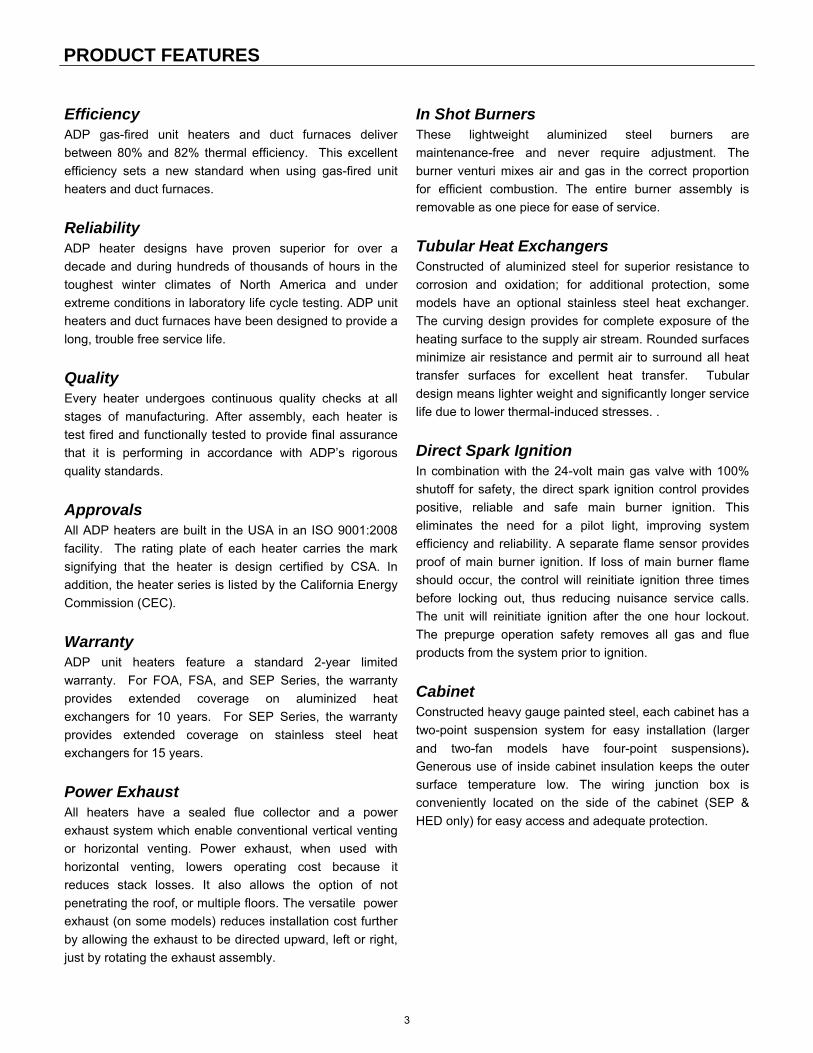
Efficiency ADP gas-fired unit heaters and duct furnaces deliver
between 80% and 82% thermal efficiency. This excellent
efficiency sets a new standard when using gas-fired unit
heaters and duct furnaces.
Reliability
ADP heater designs have proven superior for over a
decade and during hundreds of thousands of hours in the
toughest winter climates of North America and under
extreme conditions in laboratory life cycle testing. ADP unit
heaters and duct furnaces have been designed to provide a
long, trouble free service life.
Quality Every heater undergoes continuous quality checks at all
stages of manufacturing. After assembly, each heater is
test fired and functionally tested to provide final assurance
that it is performing in accordance with ADP’s rigorous
quality standards.
Approvals
All ADP heaters are built in the USA in an ISO 9001:2008
facility. The rating plate of each heater carries the mark
signifying that the heater is design certified by CSA. In
addition, the heater series is listed by the California Energy
Commission (CEC).
Warranty
ADP unit heaters feature a standard 2-year limited
warranty. For FOA, FSA, and SEP Series, the warranty
provides extended coverage on aluminized heat
exchangers for 10 years. For SEP Series, the warranty
provides extended coverage on stainless steel heat
exchangers for 15 years.
Power Exhaust All heaters have a sealed flue collector and a power
exhaust system which enable conventional vertical venting
or horizontal venting. Power exhaust, when used with
horizontal venting, lowers operating cost because it
reduces stack losses. It also allows the option of not
penetrating the roof, or multiple floors. The versatile power
exhaust (on some models) reduces installation cost further
by allowing the exhaust to be directed upward, left or right,
just by rotating the exhaust assembly.
In Shot Burners These lightweight aluminized steel burners are
maintenance-free and never require adjustment. The
burner venturi mixes air and gas in the correct proportion
for efficient combustion. The entire burner assembly is
removable as one piece for ease of service.
Tubular Heat Exchangers Constructed of aluminized steel for superior resistance to
corrosion and oxidation; for additional protection, some
models have an optional stainless steel heat exchanger.
The curving design provides for complete exposure of the
heating surface to the supply air stream. Rounded surfaces
minimize air resistance and permit air to surround all heat
transfer surfaces for excellent heat transfer. Tubular
design means lighter weight and significantly longer service
life due to lower thermal-induced stresses. .
Direct Spark Ignition In combination with the 24-volt main gas valve with 100%
shutoff for safety, the direct spark ignition control provides
positive, reliable and safe main burner ignition. This
eliminates the need for a pilot light, improving system
efficiency and reliability. A separate flame sensor provides
proof of main burner ignition. If loss of main burner flame
should occur, the control will reinitiate ignition three times
before locking out, thus reducing nuisance service calls.
The unit will reinitiate ignition after the one hour lockout.
The prepurge operation safety removes all gas and flue
products from the system prior to ignition.
Cabinet Constructed heavy gauge painted steel, each cabinet has a
two-point suspension system for easy installation (larger
and two-fan models have four-point suspensions).
Generous use of inside cabinet insulation keeps the outer
surface temperature low. The wiring junction box is
conveniently located on the side of the cabinet (SEP &
HED only) for easy access and adequate protection.
PRODUCT FEATURES
4
FSA SERIES
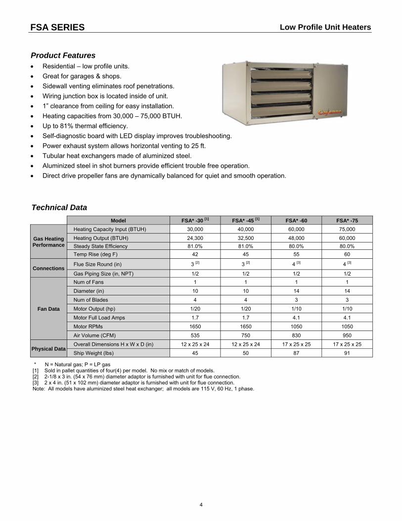
Product Features Residential – low profile units.
Great for garages & shops.
Sidewall venting eliminates roof penetrations.
Wiring junction box is located inside of unit.
1” clearance from ceiling for easy installation.
Heating capacities from 30,000 – 75,000 BTUH.
Up to 81% thermal efficiency.
Self-diagnostic board with LED display improves troubleshooting.
Power exhaust system allows horizontal venting to 25 ft.
Tubular heat exchangers made of aluminized steel.
Aluminized steel in shot burners provide efficient trouble free operation.
Direct drive propeller fans are dynamically balanced for quiet and smooth operation.
Model FSA* -30 [1] FSA* -45 [1] FSA* -60 FSA* -75
Gas Heating Performance
Heating Capacity Input (BTUH) 30,000 40,000 60,000 75,000
Heating Output (BTUH) 24,300 32,500 48,000 60,000
Steady State Efficiency 81.0% 81.0% 80.0% 80.0%
Temp Rise (deg F) 42 45 55 60
Connections Flue Size Round (in) 3 [2] 3 [2] 4 [3] 4 [3]
Gas Piping Size (in, NPT) 1/2 1/2 1/2 1/2
Fan Data
Num of Fans 1 1 1 1
Diameter (in) 10 10 14 14
Num of Blades 4 4 3 3
Motor Output (hp) 1/20 1/20 1/10 1/10
Motor Full Load Amps 1.7 1.7 4.1 4.1
Motor RPMs 1650 1650 1050 1050
Air Volume (CFM) 535 750 830 950
Physical Data Overall Dimensions H x W x D (in) 12 x 25 x 24 12 x 25 x 24 17 x 25 x 25 17 x 25 x 25
Ship Weight (lbs) 45 50 87 91
* N = Natural gas; P = LP gas [1] Sold in pallet quantities of four(4) per model. No mix or match of models. [2] 2-1/8 x 3 in. (54 x 76 mm) diameter adaptor is furnished with unit for flue connection. [3] 2 x 4 in. (51 x 102 mm) diameter adaptor is furnished with unit for flue connection. Note: All models have aluminized steel heat exchanger; all models are 115 V, 60 Hz, 1 phase.
Technical Data
Low Profile Unit Heaters

5
FSA SERIES
18−1/2(470)
18−1/2(470)
25(635)
6(152)
C
B
A
1(25)
1(25)
1(25)
ADJUSTABLELOUVERS
FLUEOUTLET
AIRFLOW
HANGINGBRACKETS (2)
DIRECTDRIVE FAN SIDE VIEW
BACK VIEW
TOP VIEW
GAS INLET
HEATEXCHANGER
SERVICEACCESSPANEL
MOUNTING SLOTS (Typical)5/16 x 3 Inches (8 x 76 mm)2−3/4
(70)
12−1/2(318)
6−1/2(165)
6−1/2(165)
12−1/2(318)
2−3/4(70)
1/2(13)
HANGINGBRACKETS (2)
ELECTRICALINLETS
NOTE − Unit may be rotated 180 top for bottomto change gas, electrical and flue positions.Hanging brackets may be installed oneither top or bottom of unit.
AIRFLOW
Model Size
A B C
in. mm in. mm in. mm
30 45
12 305 5-1/2 140 4-1/4 108
60 75
17 432 6-1/2 165 6-3/4 171
Dimensions
Low Profile Unit Heaters
NOTE: Unit may be rotated 180° top for bottom to change gas, electrical and flue positions. Hanging brackets may be installed on either top or bottom of unit.

6
FOA SERIES
Product Features Perfect for light commercial and greenhouse applications.
Introduces clean combustible outside air when required.
Wiring junction box is located outside of unit.
Ideal for hard-to-heat applications where excessive dust, dirt,
humidity, or negative pressure is a concern.
Heating capacities from 40,000 – 300,000 BTUH.
Up to 82% thermal efficiency.
Compact cabinet design on 40,000 – 75,000 BTUH models.
Hinged door allows easy access to components.
Sidewall venting eliminates roof penetrations.
Self-diagnostic board with LED display improves troubleshooting efficiency and accuracy.
Tubular heat exchangers made of aluminized steel.
Power exhaust system allows horizontal venting to 25 ft.
Direct drive propeller fans are dynamically balanced for quiet and smooth operation.
Model FOA* -45 FOA* -100 FOA* -125 FOA* -150 [1] FOA* -250 [1] FOA* -300 [1]
Gas Heating Performance
Heating Capacity Input (BTUH) 40,000 100,000 125,000 150,000 240,000 300,000
Output Natural Gas (BTUH) 32,400 81,000 101,500 120,000 194,400 240,000
Output LPG / Propane (BTUH) 32,400 82,700 101,500 121,500 196,800 243,000
Thermal Efficiency -- Natural Gas 81% 82% 81% 80% 81% 80%
Thermal Efficiency -- LPG / Propane 81% 81% 81% 81% 82% 81%
Temp Rise (deg F) 45 31 39 38 35 43
Connections
Flue Size Round (in) 3 5 5 5 5 6
Combustion Air Size Round (in) 3 4 4 4 4 4
Gas Piping Size (in, NPT)
1/2 1/2 1/2 1/2 3/4 3/4
Fan Data [2]
Number of Fans 1 1 1 1 2 2
Diameter (in) 10 16 16 18 16 16
Number of Blades 5 4 4 4 4 4
Motor Output (hp) 1/20 1/8 1/8 1/8 1/8 1/8
Motor Full Load Amps 1.7 2.7 2.7 2.7 2.7 2.7
Motor RPMs 1650 1075 1075 1075 1075 1075
Air Vol. (CFM) 750 2435 2435 2955 5215 5215
Physical Data
Overall Dimensions H x W x D (in)
12 x 26 x 24 21 x 36-1/2 x
39-5/8 21 x 36-1/2 x
39-5/8 27 x 36-1/2 x
39-5/8 39 x 36-1/2 x
39-5/8 39 x 36-1/2 x
39-5/8
Ship Weight (lbs) 84 188 204 261 307 323
* N = Natural gas; P = LP gas [1] Models not approved for residential applications. [2] Fan motor type: SP for models 45; PSC for models 100, 125, 150, 250, 300. Note: All models are 115 V, 60 Hz, 1 phase.
Technical Data
Separated Combustion Unit Heaters
7
045 MODEL
18-1/2(470)
HANGINGBRACKETS (2)
THUMBSCREW
SIDE VIEWADJUSTABLE
LOUVERS
HEATEXCHANGER
AIRFLOW
DIRECTDRIVE FAN
1(25)
FLUEOUTLET
5-3/4(146)
26(660)
GASINLET
ELECTRICALBOX
COMBUSTION AIRINLET
BACK VIEW
HANGINGBRACKETS
(2) 3(76)
13(330)
7(178)
7-1/4(184)
3-1/4(83)
1/2(13)
1(25)
18-1/2(470)
MOUNTING SLOTS (Typical)5/16 x 3 Inches (8 x 76 mm)
TOP VIEW
(25)1
13 (330)
BURNER VIEWING PORT
SERVICEACCESS
DOOR12
(305)4-1/4 (108)
1-3/4(44)
5-1/4 (133)
5-1/2 (140)
FOA SERIES
100 / 125 / 150 / 250 / 300 MODELS
7−3/4(197)
7 (178)
B
BACK VIEW
ELECTRICBOX
FLUEOUTLET
1 DIRECTDRIVE FAN
COMBUSTION AIR INLET
A
7−3/8(187)
36−1/2(927)
GAS INLET
32−3/8(822)
7−1/4 (184)1/2(13)
21−5/16(541)
5−1/2(140)
24−7/16(621)
TOP VIEW
HEATEXCHANGER
AIR FLOW
THREADED STUDS
SIDE VIEW
32−3/8(822)
THUMBSCREW
SERVICEACCESS
DOOR
BURNER VIEWINGPORT
ADJUSTABLELOUVERS
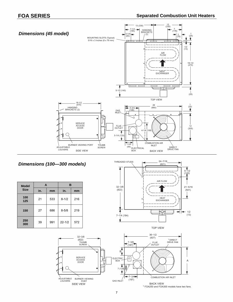
1 FOA250 and FOA300 models have two fans.
Dimensions (45 model)
Model Size
A B
in. mm in. mm
100 125
21 533 8-1/2 216
150 27 686 8-5/8 219
250 300
39 991 22-1/2 572
Separated Combustion Unit Heaters
Dimensions (100—300 models)

8
SEP SERIES
Product Features Heating capacities from 100,000 – 400,000 BTUH.
Up to 80.5% thermal efficiency.
Stainless steel heat exchanger is available for longer product life.
Heat exchangers are laboratory life-cycle tested.
Tubular heat exchangers made of aluminized steel or stainless steel.
Aluminized steel in shot burners provide efficient trouble free operation.
Sidewall venting eliminates roof penetrations.
Wiring junction box is located outside of unit.
Safe direct spark ignition. No standing pilot light.
Self-diagnostic board with LED display improves troubleshooting efficiency and accuracy.
3/8 x 16 rivet nuts are located on the top of cabinet for suspending unit using threaded rod.
Power exhaust system with a sealed flue collector allows conventional vertical or horizontal venting to 35 ft
(depends on unit size).
Direct drive propeller fans are dynamically balanced for quiet, smooth operation.
Commercial Unit Heaters
Model SEP
-100#-& SEP
-115#-& SEP
-145#-& SEP
-175#-& SEP
-200#-& SEP
-230#-& SEP
-250#-& SEP
-300#-& SEP
-345#-& SEP
-400#-&
Gas Heating Perfor-mance
Heating Capacity Input (BTUH)
100,000 115,000 145,000 172,500 195,000 230,000 250,000 300,000 345,000 390,000
Output Natural Gas (BTUH)
80,500 92,000 116,000 138,000 156,000 184,000 201,250 241,500 276,000 312,000
Output LPG/Propane (BTUH)
82,000 92,000 115,000 138,000 156,000 184,000 205,000 246,000 281,200 312,000
Steady State Efficiency -- Natural Gas
80.5% 80.0% 80.0% 80.0% 80.0% 80.0% 80.5% 80.5% 80.0% 80.0%
Steady State Efficiency -- LPG / Propane
82.0% 80.0% 80.0% 80.0% 80.0% 80.0% 82.0% 82.0% 81.5% 80.0%
Connec-tions
Flue Size Round (in) 4 [1] 4 [1] 4 [1] 5 [2] 5 [2] 5 [2] 5 [2] 5 [2] 6 [3] 6 [3]
Gas Piping Size (in, NPT)
1/2 1/2 1/2 1/2 1/2 3/4 3/4 3/4 3/4 3/4
Fan Data
Number of Fans 1 1 1 1 1 2 2 2 2 2
Diameter (in) 16 16 16 16 16 16 16 16 16 16
Number of Blades 4 4 4 4 4 4 4 4 4 5
Motor Output (hp) 1/8 1/8 1/8 1/8 1/8 1/8 1/8 1/8 1/8 1/8
Motor Full Load Amps 2.1 2.1 2.1 2.1 2.1 2.1 2.1 2.1 2.1 2.1
Motor RPMs 1075 1075 1075 1075 1075 1075 1075 1075 1075 1075
Air Volume (CFM) 1900 1900 1900 2200 2200 4400 4400 4400 4400 4400
Physical Data
Overall Dimensions H x W x D (in)
32-3/16 x 20-3/16 x 39-3/16
32-3/16 x 20-3/16 x 39-3/16
32-3/16 x 20-3/16 x 39-3/16
32-3/16 x 23-1/8 x 39-3/16
32-3/16 x 23-1/8 x
40
32-3/16 x 41-1/8 x
40
32-3/16 x 41-1/8 x
40
32-3/16 x 41-1/8 x
40
32-3/16 x 41-1/8 x 41-1/8
32-3/16 x 41-1/8 x 41-1/8
Ship Weight (lbs) 150 150 165 185 185 275 275 280 310 315
[1] 2-1/8 x 4 in. (54 x 102 mm) diameter adaptor is furnished with unit for flue connection. [2] 2-1/4 x 2-3/4 in. (57 x 70 mm) rectangular to 5 in. (127 mm) round adaptor is furnished with unit for flue connection. [3] 2-1/4 x 2-3/4 in. (57 x 70 mm) rectangular to 6 in. (152 mm) round adaptor is furnished with unit for flue connection. # A = Aluminized steel heat exchanger; S = Stainless steel heat exchanger; All models are 115 volts, 60 Hz, 1 phase. & N = Natural Gas; P = LP Gas Note: SEP unit heaters are not approved for residential applications.
Technical Data
9
1/2 (13)
TOP VIEW
SIDE VIEW
ADJUSTABLELOUVERS
GASVALVEHEAT
EXCHANGER
DIRECTDRIVE FAN
FLUEOUTLET
ELECTRICAL INLETS
3/8-16 RIVETNUTSFOR UNIT SUSPENSION
AIR
FLOW
COMBUSTION AIRINDUCER
FRONT VIEW
A
C
D
E
B*7-5/8(194) 1/2
(13)
F
32-3/16(817)
31-5/16(795)
SEP SERIES
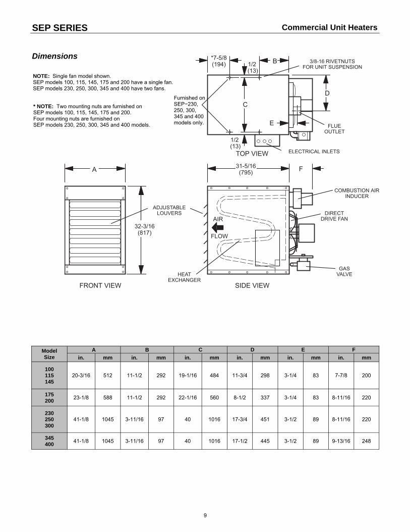
NOTE: Single fan model shown. SEP models 100, 115, 145, 175 and 200 have a single fan. SEP models 230, 250, 300, 345 and 400 have two fans.
* NOTE: Two mounting nuts are furnished on SEP models 100, 115, 145, 175 and 200. Four mounting nuts are furnished on SEP models 230, 250, 300, 345 and 400 models.
Furnished on SEP−230, 250, 300, 345 and 400 models only.
Model Size
A B C D E
in. mm in. mm in. mm in. mm in. mm in. mm
100 115 145
20-3/16 512 11-1/2 292 19-1/16 484 11-3/4 298 3-1/4 83 7-7/8 200
175 200
23-1/8 588 11-1/2 292 22-1/16 560 8-1/2 337 3-1/4 83 8-11/16 220
F
230 250 300
41-1/8 1045 3-11/16 97 40 1016 17-3/4 451 3-1/2 89 8-11/16 220
345 400
41-1/8 1045 3-11/16 97 40 1016 17-1/2 445 3-1/2 89 9-13/16 248
Commercial Unit Heaters
Dimensions
10
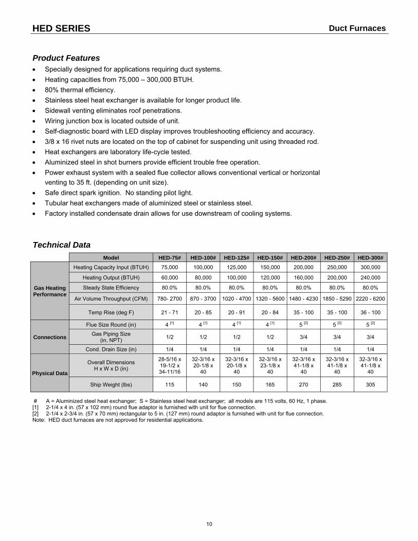
HED SERIES
Product Features Specially designed for applications requiring duct systems.
Heating capacities from 75,000 – 300,000 BTUH.
80% thermal efficiency.
Stainless steel heat exchanger is available for longer product life.
Sidewall venting eliminates roof penetrations.
Wiring junction box is located outside of unit.
Self-diagnostic board with LED display improves troubleshooting efficiency and accuracy.
3/8 x 16 rivet nuts are located on the top of cabinet for suspending unit using threaded rod.
Heat exchangers are laboratory life-cycle tested.
Aluminized steel in shot burners provide efficient trouble free operation.
Power exhaust system with a sealed flue collector allows conventional vertical or horizontal
venting to 35 ft. (depending on unit size).
Safe direct spark ignition. No standing pilot light.
Tubular heat exchangers made of aluminized steel or stainless steel.
Factory installed condensate drain allows for use downstream of cooling systems.
Model HED-75# HED-100# HED-125# HED-150# HED-200# HED-250# HED-300#
Gas Heating Performance
Heating Capacity Input (BTUH) 75,000 100,000 125,000 150,000 200,000 250,000 300,000
Heating Output (BTUH) 60,000 80,000 100,000 120,000 160,000 200,000 240,000
Steady State Efficiency 80.0% 80.0% 80.0% 80.0% 80.0% 80.0% 80.0%
Air Volume Throughput (CFM) 780- 2700 870 - 3700 1020 - 4700 1320 - 5600 1480 - 4230 1850 - 5290 2220 - 6200
Temp Rise (deg F) 21 - 71 20 - 85 20 - 91 20 - 84 35 - 100 35 - 100 36 - 100
Connections
Flue Size Round (in) 4 [1] 4 [1] 4 [1] 4 [1] 5 [2] 5 [2] 5 [2]
Gas Piping Size (in, NPT)
1/2 1/2 1/2 1/2 3/4 3/4 3/4
Cond. Drain Size (in) 1/4 1/4 1/4 1/4 1/4 1/4 1/4
Physical Data
Overall Dimensions H x W x D (in)
28-5/16 x 19-1/2 x 34-11/16
32-3/16 x 20-1/8 x
40
32-3/16 x 20-1/8 x
40
32-3/16 x 23-1/8 x
40
32-3/16 x 41-1/8 x
40
32-3/16 x 41-1/8 x
40
32-3/16 x 41-1/8 x
40
Ship Weight (lbs) 115 140 150 165 270 285 305
# A = Aluminized steel heat exchanger; S = Stainless steel heat exchanger; all models are 115 volts, 60 Hz, 1 phase. [1] 2-1/4 x 4 in. (57 x 102 mm) round flue adaptor is furnished with unit for flue connection. [2] 2-1/4 x 2-3/4 in. (57 x 70 mm) rectangular to 5 in. (127 mm) round adaptor is furnished with unit for flue connection. Note: HED duct furnaces are not approved for residential applications.
Technical Data
Duct Furnaces

11
HED SERIES
Unit Size Air
Volume (CFM)
Total Resistance
(inches W.C)
Temp Rise
(deg F)
75
780 0.01 71
1000 0.02 56
1300 0.05 43
1600 0.07 35
1900 0.10 29
2200 0.12 25
2500 0.17 22
2700 0.20 21
100
870 0.02 85
900 0.02 82
1300 0.03 57
1700 0.06 44
2100 0.09 35
2500 0.12 30
2900 0.15 26
3300 0.18 22
3700 0.23 20
125
1020 0.03 91
1100 0.03 84
1600 0.06 58
2100 0.11 44
2600 0.16 36
3100 0.21 30
3600 0.26 26
4100 0.31 23
4600 0.36 20
4700 0.37 20
150
1320 0.02 84
1400 0.03 79
2000 0.07 56
2600 0.12 43
3200 0.20 35
3800 0.28 29
4400 0.37 25
5000 0.45 22
5600 0.55 20
Unit Size Air
Volume (CFM)
Total Resistance
(inches W.C)
Temp Rise
(deg F)
200
1480 0.03 100
1500 0.03 99
2000 0.04 74
2500 0.07 59
3000 0.09 49
3500 0.13 42
4000 0.15 37
4230 0.16 35
250
1850 0.04 100
2000 0.05 93
2500 0.08 74
3000 0.11 62
3500 0.13 53
4000 0.17 46
4500 0.19 41
5000 0.23 37
5290 0.25 35
300
2220 0.07 100
2800 0.11 79
3400 0.14 65
4000 0.18 56
4600 0.23 48
5200 0.26 43
5800 0.31 38
6190 0.33 36
6200 0.33 36
Performance Ratings
Duct Furnaces
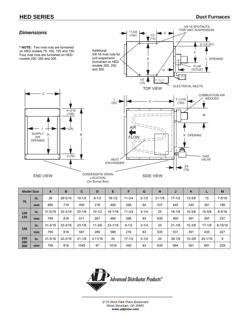
HED SERIES
Model Size A B C D E F G H J K L M
75 in. 26 28-5/16 19-1/2 8-1/2 18-1/2 11-3/4 2-1/2 21-1/8 17-1/2 13-3/8 15 7-5/16
mm 660 719 495 216 469 298 64 537 445 340 381 186
100 125
in. 31-5/16 32-3/16 20-1/8 10-1/2 19-1/16 11-3/4 3-1/4 25 18-1/8 15-3/8 15-5/8 9-5/16
mm 795 818 511 267 484 298 83 635 460 391 397 237
150 in. 31-5/16 32-3/16 23-1/8 11-3/8 23-1/16 8-1/2 3-1/4 25 21-1/8 15-3/8 17-1/8 8-15/16
mm 795 818 587 289 586 216 83 635 537 391 435 227
200 250 300
in. 31-5/16 32-3/16 41-1/8 3-11/16 40 17-1/2 3-1/4 25 39-1/8 15-3/8 35-1/16 9
mm 795 818 1045 97 1016 445 83 635 994 391 891 229
Duct Furnaces
Dimensions
* NOTE: Two rivet nuts are furnished on HED models 75, 100, 125 and 150. Four rivet nuts are furnished on HED models 200, 250 and 300
Additional 3/8-16 rivet nuts for unit suspension (furnished on HED models 200, 250 and 300.
COMBUSTION AIRINDUCER
1/2 (13)
7-11/16(195)
TOP VIEW
SIDE VIEW
GASVALVEHEAT
EXCHANGER
FLUEOUTLET
ELECTRICAL INLETS
AIR
FLOW
END VIEW
A
B
C
E
F
G
D*7-5/8(194) 1/2
(13)
3/8-16 SPOTNUTSFOR UNIT SUSPENSION
L
KH
J
OPENING
OPENINGSUPPLYAIR
OPENING
1(25)
3/4(19)
2−1/4 (57)
4−3/16(106)
3 (76)
1(25)
M
CONDENSATE DRAINLOCATION
(On Burner Box)