fry holding unit (fhu & fhuas) - duke burger king
TRANSCRIPT

Service Manual
FRY HOLDING UNIT (FHU & FHUAS)
This manual is Copyright © 2016 Duke Manufacturing Co. All rights reserved. Reproduction without written permission is prohibited. Duke is a registered
trademark of the Duke Manufacturing Co.
Duke Manufacturing Co.2305 N. Broadway
St. Louis, MO 63102Phone: 314-231-1130
Toll Free: 1-800-735-3853Fax: 314-231-5074
www.dukemfg.com
Please read this manual completely before attempting to install, operate or service this equipment.
This document is prepared for trained Duke service technicians. It is not to be used by anyone not properly qualified to perform these procedures.
This Service Manual is not all encompassing. If you have not been trained on servicing this product, be sure to read the manual completely before attempting servicing. Be sure all necessary tools, test equipment, and skills are available. Those procedures for which you do not have the proper skills and test equipment must be performed only by a qualified Duke trained service technician.
MODELS
FHU-1FHU-2FHUAS-2
10/31/2016SM-BK-FR-0004

Service Manual for Fry Station (FHU & FHUAS)
2 SM-BK-FR-000410/31/2016
APPLIANCES EquIPPED wITh A FLExIBLE ELECTRIC SuPPLy CORD, ARE PROvIDED wITh A tHree-Prong groUnDing PlUg. it iS imPerAtive tHAt tHiS PlUg Be connecteD into A ProPerly groUnDeD tHree-Prong recePtAcle. FAilUre to COMPLy wITh ThIS PROCEDuRE CAN CAuSE PROPERTy DAmAge, injUry or DeAtH.
IF ThE RECEPTACLE IS NOT ThE PROPER groUnDing tyPe, contAct An electriciAn. Do not remove tHe groUnDing Prong From tHe PlUg. FAILuRE TO COMPLy wITh ThIS PROCEDuRE CAN CAuSE ProPerty DAmAge, injUry or DeAtH.
BeFore PerForming Any Service T h AT I N vO Lv ES E L EC T R I C A L CO N N EC T I O N O R DISCONNECTION AND/OR ExPOSuRE TO ELECTRICAL COMPONENTS, ALwAyS PERFORM ThE ELECTRICAL locKoUt/tAgoUt ProceDUre. DiSconnect All CIRCuITS. FAILuRE TO COMPLy wITh ThIS PROCEDuRE cAn cAUSe ProPerty DAmAge, injUry or DeAtH.
BeFore removing Any SHeet metAl PAnelS or Servicing tHiS eqUiPment, AlwAyS PerForm tHe electricAl locKoUt/tAgoUt PROCEDuRE. BE SuRE ALL CIRCuITS ARE DISCONNECTED. FAILuRE TO COMPLy wITh ThIS PROCEDuRE CAN CAuSE ProPerty DAmAge, injUry or DeAtH.
DO NOT OPERATE ThIS EquIPMENT witHoUt ProPerly PlAcing AnD SecUring All COvERS AND ACCESS PANELS. FAILuRE TO COMPLy witH tHiS ProceDUre cAn cAUSe ProPerty DAmAge, injUry or DeAtH.
Do not USe or Store gASoline or OThER FLAMMABLE vAPORS OR LIquIDS IN ThE vICINITy OF ThIS OR ANy OThER APPLIANCE. FAILuRE TO COMPLy cAn cAUSe ProPerty DAmAge, injUry or DeAtH.
IN ThE EvENT OF A POwER FAILuRE, DO NOT ATTEMPT TO OPERATE ThIS APPLIANCE. FAILuRE to comPly cAn cAUSe ProPerty DAmAge, injUry OR DEATh.
imPortAnt wArning AnD SAFety inFormAtion ThIS MANuAL hAS BEEN PREPARED FOR PERSONNEL quALIFIED TO INSTALL ELECTRICAL EquIPMENT, whO ShOuLD PerForm tHe initiAl FielD StArtUP AnD ADjUStmentS oF tHe eqUiPment covereD By tHiS mAnUAl.
reAD tHiS mAnUAl tHoroUgHly BeFore oPerAting, inStAlling or PerForming mAintenAnce ON ThE EquIPMENT.
FAILuRE TO FOLLOw ALL ThE INSTRuCTIONS IN ThIS MANuAL CAN CAuSE ProPerty DAmAge, injUry or DeAtH.
I M P R O P E R I N S TA L L AT I O N , ADjUStment, AlterAtion, Service or mAintenAnce cAn cAUSe ProPerty DAmAge, injUry or DeAtH.
ELECTRICAL CONNECTIONS ShOuLD BE PERFORMED ONLy By A CERTIFIED PROFESSIONAL.
electricAl AnD groUnDing CONNECTIONS MuST COMPLy wITh ThE APPLICABLE PORTIONS OF ThE NATIONAL ELECTRIC CODE AND/OR ALL LOCAL ELECTRIC CODES. FAILuRE TO COMPLy wITh tHiS ProceDUre cAn cAUSe ProPerty DAmAge, injUry or DeAtH.
BeFore connecting tHe Unit to ThE ELECTRICAL SuPPLy, vERIFy ThAT ThE ELECTRICAL AnD groUnDing connectionS comPly witH tHe APPLICABLE PORTIONS OF ThE NATIONAL ELECTRIC CODE AND/OR OThER LOCAL ELECTRICAL CODES. FAILuRE TO COMPLy wITh ThIS PROCEDuRE CAN CAuSE PROPERTy DAmAge, injUry or DeAtH.
BeFore connecting tHe Unit to ThE ELECTRICAL SuPPLy, vERIFy ThAT ThE ELECTRICAL connection AgreeS witH tHe SPeciFicAtionS on tHe DATA PLATE. FAILuRE TO COMPLy wITh ThIS PROCEDuRE cAn cAUSe ProPerty DAmAge, injUry or DeAtH.
Ul73 groUnDing inStrUctionS: tHiS APPliAnce mUSt Be connecteD to A groUnDeD, metAl, PermAnent wiring SyStem. or An eqUiPment-groUnDing conDUctor mUSt Be rUn wITh ThE CIRCuIT CONDuCTORS AND CONNECTED to tHe eqUiPment-groUnDing terminAl or leAD ON ThE APPLIANCE. FAILuRE TO COMPLy wITh ThIS ProceDUre cAn cAUSe ProPerty DAmAge, injUry OR DEATh.

Service Manual for Fry Station (FHU & FHUAS)
3SM-BK-FR-0004 10/31/2016
TABLE OF CONTENTS
INTRODUCTION ..................................................................................................................................................................5
INSTALLATION ..............................................................................................................................................................5
OPERATION ..................................................................................................................................................................5
CLEANING ....................................................................................................................................................................5
SEQUENCE OF OPERATION ..........................................................................................................................................5
TOOLS ..........................................................................................................................................................................5
SPECIFICATIONS ..................................................................................................................................................................6
ELECTRICAL SPECIFICATIONS .......................................................................................................................................6
DIMENSIONS ...............................................................................................................................................................6
REMOVAL AND REPLACEMENT OF PARTS ..........................................................................................................................7
ELECTRICAL LOCKOUT/TAGOUT PROCEDURE ..............................................................................................................7
ESD WRIST STRAP ........................................................................................................................................................7
FHU ELECTRICAL COMPONENTS .................................................................................................................................8
AC INPUT VOLTAGE WIRING CONNECTIONS ........................................................................................................8
POWER ON/OFF SWITCHES ..................................................................................................................................8
CONTROLLERS ......................................................................................................................................................9
COOLING FANS .....................................................................................................................................................9
DC POWER SUPPLIES ..........................................................................................................................................10
SOLID STATE RELAYS (HEAT RELAYS) ...................................................................................................................11
CONTACTORS (POWER RELAYS) ..........................................................................................................................11
CONTROL COMPARTMENT .................................................................................................................................12
CRUMB TRAY INTERLOCK SWITCHES ..................................................................................................................13
CRUMB TRAY MAGNETS .....................................................................................................................................14
THERMOCOUPLES ..............................................................................................................................................14
HEATER/FAN ASSEMBLIES (CONTROL SIDE) .......................................................................................................15
HEATER/FAN ASSEMBLIES (REAR SIDE) ..............................................................................................................17
CALROD HEATERS (CONTROL SIDE) ....................................................................................................................19
CALROD HEATERS (REAR SIDE) ...........................................................................................................................20
FAN ASSEMBLIES (CONTROL SIDE w/CALROD HEATERS) ...................................................................................21
FAN ASSEMBLIES (REAR SIDE w/CALROD HEATERS) ..........................................................................................23
HIGH LIMIT THERMOSTATS (CONTROL SIDE w/CALROD-STYLE HEATER) ...........................................................25
HIGH LIMIT THERMOSTATS (REAR SIDE w/CALROD-STYLE HEATER) ..................................................................26
FHUAS ELECTRICAL COMPONENTS ...........................................................................................................................27
POWER ON/OFF SWITCHES ................................................................................................................................27
CAPACITORS .......................................................................................................................................................28
FANS ...................................................................................................................................................................29
HEATERS .............................................................................................................................................................31
HIGH LIMIT THERMOSTATS ................................................................................................................................33
(continued on following page)

Service Manual for Fry Station (FHU & FHUAS)
4 SM-BK-FR-000410/31/2016
FHU PROGRAMMING INSTRUCTIONS ..............................................................................................................................35
PROGRAMMING AND DISPLAYING PARAMETERS (FOUR RECIPES) ...........................................................................35
PROGRAMMING PARAMETERS .................................................................................................................................37
FHU TROUBLESHOOTING .................................................................................................................................................38
FHU TROUBLESHOOTING GUIDE ...............................................................................................................................39
FHUAS TROUBLESHOOTING GUIDE ...........................................................................................................................39
WIRING DIAGRAMS ..........................................................................................................................................................40
FHU-2 WITH CALROD HEATERS (229818) ..................................................................................................................40
FHU-2 WITH COIL HEATERS (229818) ........................................................................................................................41
FHU-1 WITH COIL HEATER (229817) ..........................................................................................................................42
FHU-1 WITH CALROD HEATER (229817) ....................................................................................................................43
FHU-2 WITH COIL HEATERS, FOR EMEA (229836) .....................................................................................................44
ELECTRICAL CHASE ....................................................................................................................................................45
FHU-2 ELECTRICAL CHASE, INLINE (229935) .............................................................................................................45
FHU-2 ELECTRICAL CHASE, STANDALONE (229938) ..................................................................................................45
FHU-2 Electrical Chase, Inline (229935) ....................................................................................................................46
FHU-2 Electrical Chase, Standalone (229938) ...........................................................................................................46
FHU-2 (CE) Electrical Chase, Inline (229816) .............................................................................................................47
FHU-2 (CE) Electrical Chase, Standalone (229815) ....................................................................................................47
FHU-2 (Japan) Electrical Chase, Standalone (229835) ...............................................................................................48
FHU-1 Electrical Chase, Inline (229939) ....................................................................................................................48
FHU-1 Electrical Chase, Standalone (229937) ...........................................................................................................49
FHU-1 (CE) Electrical Chase, Standalone (229834) ....................................................................................................49
FHU-1 (Japan) Electrical Chase, Standalone (229813) ...............................................................................................50
FHU-1 (China) Electrical Chase, Inline (229944) ........................................................................................................50
FHUAS (229014) ........................................................................................................................................................51
FHUAS Electrical Chase, Inline (229981) ...................................................................................................................52
FHUAS Electrical Chase, Standalone (229949) ..........................................................................................................52
Service Manual for Fry Station (FHU & FHUAS)
5SM-BK-FR-0004 10/31/2016
INTRODuCTION
INSTALLATIONFor detailed installation instructions, refer to the Owner’s Manual
OPERATIONFor specific operating instructions, refer to the Owner’s Manual
cleAningFor specific instructions, refer to the Owner’s Manual
SEquENCE OF OPERATIONFor specific instructions, refer to the Owner’s Manual
TOOLS• Standard set of hand tools.
• VOM with AC current tester. (Any quality VOM or DVM with a sensitivity of at least 20,000 Ohms per Volt can be used.)

Service Manual for Fry Station (FHU & FHUAS)
6 SM-BK-FR-000410/31/2016
SPECIFICATIONS US and Foreign Patent(s) Pending
ELECTRICAL SPECIFICATIONS
MODEL Ac voltAge hZ PhASE AmPerAge (mAX.) uNIT wT. SHiPPing wt.
FHU1208/230/240 50/60 1 18
310 lbs / 141 kg 370 lbs / 168 kg200 50/60 1 24
FHU2208/230/240 50/60 1 36
525 lbs / 238 kg 585 lbs / 265 kg200 50/60 1 48
FHUAS2120 60 1 32
310 lbs / 141 kg 370 lbs / 168 kg230 50 1 15
DIMENSIONS
16"
36"
20 1/2"
FHU1
36"
42"
FHU2
36"
42"
36"
16"
36"
FHUAS
34"
36"

Service Manual for Fry Station (FHU & FHUAS)
7SM-BK-FR-0004 10/31/2016
REMOvAL AND REPLACEMENT OF PARTS
electricAl locKoUt/tAgoUt ProceDUre
wArning
BEFORE PERFORMING ANY SERVICE THAT INVOLVES ELECTRICAL CONNECTION OR DISCONNECTION AND/OR ExPOSURE TO
ELECTRICAL COMPONENTS, ALWAYS FOLLOW THE ELECTRICAL LOCKOUT/TAGOUT PROCEDURE. DISCONNECT ALL CIRCUITS. FAILURE TO COMPLY
CAN CAUSE PROPERTY DAMAGE, INJURY OR DEATH.
The Electrical LOCKOUT/TAGOUT Procedure is used to protect personnel working on an electrical appliance. Before performing any maintenance or service that requires exposure to electrical components, follow these steps:
1. In electrical box, place appliance circuit breaker into OFF position.
2. Place a lock or other device on the electrical box cover to prevent someone from placing the circuit breaker ON.
3. Place a tag on electrical box cover to indicate that appliance has been disconnected for service and power should not be restored until tag is removed by maintenance personnel.
4. Disconnect the appliance power cord from the electrical outlet.
5. Place a tag on the cord to indicate that unit has been disconnected for service and power should not be restored until tag is removed.
ESD wRIST STRAPAn ESD Wrist Strap is required when replacing certain components.
1. Place both of the unit’s power ON/OFF Switches in the “OFF” position and follow the proper LOCKOUT/TAGOUT Procedure.
2. Remove and retain the screws securing the Control Panel to the unit.
3. Tilt the Control Panel down and away from unit far enough to access the component(s).
4. Depending on the component being replaced, properly connect the ESD Wrist Strap to the unit or Control Panel and secure it properly on the wrist.
AttachESD Strap
to unit

Service Manual for Fry Station (FHU & FHUAS)
8 SM-BK-FR-000410/31/2016
Ac inPUt voltAge wiring connectionS
The AC Input Voltage Wiring Connections are located behind the Lower Electrical Chase Cover. They control the power to all of the AC-powered equipment (lights, microwave, etc.) in the Fry Holding Unit (FHU), Overhead Refrigerated Merchandiser (OHRM), and/or Burger Station.
NOTE: The FHU Electrical Chase Wiring Diagram is located on page 34.
1. Place both of the unit’s power ON/OFF Switches in the “OFF” position and follow the proper LOCKOUT/TAGOUT Procedure.
2. To access the incoming power supply terminal block, open the control side cabinet doors.
3. Remove and retain the screws securing the Lower Electrical Chase Cover and remove the cover from the unit.
4. Use a voltmeter to check for the presence of voltage.
5. With AC power removed and LOCKOUT/TAGOUT Procedure applied, ensure that the contacts on the connect block are properly torqued as follows:
Center Terminal Blocks: 35 lb-in
Outer Terminal Blocks (varies depending on wire size):
MAIN (1) lb-in N.m.#3 – 2 AWG 50 5.6#6 – 4 45 5.1#8 40 4.5#14 – 10 35 4.0BRANCh (4) lb-in N.m.#18 – 10 AWG 7 0.8
6. Reinstall the Lower Electrical Chase Cover by reversing the previous steps.
7. Close the control side cabinet doors.
8. Restore power to the unit and test for proper function.
POwER ON/OFF SwITChES
There are two (2) Power ON/OFF Switches, one for each zone, located on the Control Panel.
1. Place both of the unit’s power ON/OFF Switches in the “OFF” position and follow the proper LOCKOUT/TAGOUT Procedure.
2. Remove and retain the screws securing the Control Panel to the Control Compartment.
3. Tilt the Control Panel down and away from unit far enough to access the Power ON/OFF Switch.
NOTE: Removing the crumb trays will allow for greater access.
4. Mark and disconnect wires to the affected Power ON/OFF Switch.
5. The Power ON/OFF Switch is secured to the Control Panel with spring clips. Depress the spring clips and slide the switch from the Control Panel.
Spring Clips
6. Install the replacement Power ON/OFF Switch by sliding it into its position in the Control Panel until secured with its spring clips. If necessary, repeat for the other switch.
7. Reattach the Power ON/OFF Switch wires.
8. Replace the Control Panel by tilting the panel inward and lifting up and securing with its screws.
9. Restore power to the unit and test for proper function.
NOTE: ThE FOLLOWING INSTrucTIONS arE WrITTEN FOr ThE Fhu2 MOdEL. AppropriAte modificAtions Are required for servicing the fhu1 (“the
mini") model, which is hAlf (1/2) the size of the fhu2.
Fhu ELECTRICAL COMPONENTS

Service Manual for Fry Station (FHU & FHUAS)
9SM-BK-FR-0004 10/31/2016
CONTROLLERS
There are two Controllers, one for each zone. They control the Solid State Relays and are operated from the Control Panel on the control side of the unit. They are located on the interior side of the Control Panel.
1. Place both of the unit’s power ON/OFF Switches in the “OFF” position and follow the proper LOCKOUT/TAGOUT Procedure.
2. Remove and retain the screws securing the Control Panel to the Control Compartment.
3. Tilt the Control Panel down and away from unit far enough to access the Controller(s).
NOTE: Removing the crumb trays will allow for greater access.
4. Using an ESD Strap (including remaining steps), mark and disconnect the wires to the affected Controller(s).
5. Remove and retain the 4 hex nuts securing the Controller(s) to the Control Panel.
6. Retain spacers on studs.
7. Install the replacement Controller by setting into place and securing with its nuts.
8. Reconnect the Controller wires.
9. Replace the Control Panel by tilting the panel inward and lifting up and securing with its screws.
10. Restore power to the unit and test for proper function.
cooling FAnS
There are two Cooling Fans. They provide ventilation to the electrical components in the Control Compartment and are located at each end of the Control Panel on the control side of the unit.
1. Place both of the unit’s power ON/OFF Switches in the “OFF” position and follow the proper LOCKOUT/TAGOUT Procedure.
2. Remove and retain the screws securing the Control Panel to the Control Compartment.
3. Tilt the Control Panel down and away from unit far enough to access the affected Cooling Fan(s).
NOTE: Removing the crumb trays will allow for greater access.
4. Remove and retain the 4 screws securing the affected Cooling Fan Louvered Housing to the Control Panel.

Service Manual for Fry Station (FHU & FHUAS)
10 SM-BK-FR-000410/31/2016
5. Mark and disconnect the wires to the affected Cooling Fan(s).
6. Remove and retain the four (4) 5/16" hex nuts securing each Cooling Fan to the Control Panel.
DisconnectFan Wires
7. Remove and retain the Control Panel wire bushing to allow the wires to be pulled through the opening.
8. Install the replacement Cooling Fan(s) into place by pulling its wires through the Control Panel opening, reinstalling the wire bushing, reconnecting its wires, and securing it in place with its screws.
9. Reinstall the Cooling Fan Louvered Housing and secure with its screws.
10. Replace the Control Panel by tilting the panel inward and lifting up and securing with its screws.
11. Restore power to the unit and test for proper function.
DC POwER SuPPLIES
There are two DC Power Supplies, one for each zone. They provide DC power to the Heater Fans and are located inside the Control Compartment.
1. Place both of the unit’s power ON/OFF Switches in the “OFF” position and follow the proper LOCKOUT/TAGOUT Procedure.
2. Remove and retain the screws securing the Control Panel to the Control Compartment.
3. Tilt the Control Panel down and away from unit far enough to access the DC Power Supplies.
NOTE: Removing the crumb trays will allow for greater access.
4. Using an ESD Strap (including remaining steps), mark and disconnect all wires and plugs attached to the affected DC Power Supply.
5. Remove and retain the four (4) 5/16” hex nuts securing the affected DC Power Supply to the Control Compartment and remove the DC Power Supply from the unit.
6. Retain spacers on studs.
7. Install the replacement DC Power Supply by setting into place and securing with its screws.
8. Reconnect the DC Power Supply wires and plugs.
9. Replace the Control Panel by tilting the panel inward and lifting up and securing with its screws.
10. Restore power to the unit and test for proper function.

Service Manual for Fry Station (FHU & FHUAS)
11SM-BK-FR-0004 10/31/2016
SOLID STATE RELAyS (hEAT RELAyS)
There are four Solid State Relays (“Heat Relays"), two for each zone. They control power to the heating elements and are located inside the Control Compartment.
1. Place both of the unit’s power ON/OFF Switches in the “OFF” position and follow the proper LOCKOUT/TAGOUT Procedure.
2. Remove and retain the screws securing the Control Panel to the Control Compartment.
3. Tilt the Control Panel down and away from unit far enough to access the Solid State Relays.
NOTE: Removing the crumb trays will allow for greater access.
4. Mark and disconnect all wires and plugs attached to the affected Solid State Relay(s).
5. Loosen the right side screw (it’s slotted) and remove and retain the left side screw for each affected Solid State Relay.
Loosenthisscrew
6. Remove the affected Solid State Relay(s) and clean the mounting surface of any residual heat transfer compound.
7. Apply heat transfer compound to the mounting surface of the replacement Solid State Relay(s).
8. Install the replacement Solid State Relay(s) and secure with its screws.
9. Reconnect the Solid State Relay wires and plugs.
10. Replace the Control Panel by tilting the panel inward and lifting up and securing with its screws.
11. Restore power to the unit and test for proper function.
CONTACTORS (POwER RELAyS)
There are two Contactors (“Power Relays"), one for each zone. They serve to interrupt power to the unit when the crumb tray is removed and are located inside the Control Compartment.
1. Place both of the unit’s power ON/OFF Switches in the “OFF” position and follow the proper LOCKOUT/TAGOUT Procedure.
2. Remove and retain the screws securing the Control Panel to the Control Compartment.
3. Tilt the Control Panel down and away from unit far enough to access the Contactors.
NOTE: Removing the crumb trays will allow for greater access.
4. Mark and disconnect all wires attached to the affected Contactor(s).
5. Remove and retain the two (2) 5/16" hex nuts securing each affected Contactor to the Control Compartment.
6. Remove the affected Contactor(s).
7. Install the replacement Contactor(s) and secure with its hex nuts.
8. Reconnect all of the Contactor wires.
9. Replace the Control Panel by tilting the panel inward and lifting up and securing with its screws.
10. Restore power to the unit and test for proper function.

Service Manual for Fry Station (FHU & FHUAS)
12 SM-BK-FR-000410/31/2016
CONTROL COMPARTMENT
The Control Compartment is located on the control side (front) of the unit, behind the Control Panel. It provides access to the control side Heater/Fan Assembly and contains the Power ON/OFF Switches, Cooling Fans, DC Power Supplies, Controllers, Contactors (Power Relays), and Solid State (Heat) Relays.
1. Place both of the unit’s power ON/OFF Switches in the “OFF” position and follow the proper LOCKOUT/TAGOUT Procedure.
2. Remove and retain the screws securing the Control Panel to the Control Compartment.
3. Tilt the panel down and away from unit far enough to access the wiring harnesses and components.
NOTE: Removing the crumb trays will allow for greater access.
4. Disconnect all molex plugs.
5. Cut all zip ties to release the compartment wires.
6. Mark and disconnect line voltage and ground wires to the terminal block.
7. Mark and disconnect the Thermocouple wires.
8. Remove and retain the screws securing the four (4) bushing covers (two towards each end).
9. Remove and retain the eight (8) screws along the bottom of the black rail that secures the black rail to the unit and Control Compartment.
Black Rail
10. Slide out the black rail that supports and holds the Control Compartment in the unit.
11. Remove the Control Compartment from the unit. If necessary, use partially opened cabinet doors as a place to help support it.
12. Replace the Control Compartment and black rail under the Control Compartment, securing with its screws.
13. Reattach all previously disconnected Control Compartment molex plugs and spade terminals.
NOTE: The terminal block connections in the Control Compartment must be torqued to 30 in-lb.
14. Tilt the Control Panel into place and secure with its screws.
15. Restore power to the unit and test for proper function.

Service Manual for Fry Station (FHU & FHUAS)
13SM-BK-FR-0004 10/31/2016
CRuMB TRAy INTERLOCK SwITChES
There are two Crumb Tray Interlock Switches, one for each tray. They prevent power from reaching the heaters or fans while the tray is removed from the unit and are located at the rear end of each tray, inside and above each rear Access Panel.
1. Place both of the unit’s power ON/OFF Switches in the “OFF” position and follow the proper LOCKOUT/TAGOUT Procedure.
2. The Carton Shelf is mounted with three keyholes. Lift the shelf up to disengage the studs and remove from the unit.
3. Remove the affected Interlock Switch’s crumb tray from the unit.
4. Remove the screws and hex nuts (under lip of unit) that secure the Upper Rear Panel to the back of unit and remove from the unit.
5. Open the rear cabinet doors of the unit.
6. On the horizontal surface behind and above the door, locate the appropriate Access Panel.
7. Remove and retain the sixteen (16) 9mm nuts securing the appropriate Access Panel and remove from the unit.
8. Remove and retain the two (2) 1/4" (6 or 7 mm) hex nuts that secure the switch shield and remove the shield.
Crumb Tray Interlock Switch
Switch Shield
9. Mark and disconnect the wiring to the affected Crumb Tray Interlock Switch.
10. Remove and retain the two (2) 1/4" (6 or 7 mm) hex nuts that secure the Crumb Tray Interlock Switch to the unit and remove the switch.
11. Install the replacement Crumb Tray Interlock Switch and its shield with their hex nuts.
12. Reinstall the Access Panel by reversing the previous steps.
IMPORTANT: Access Panels must be reinstalled correctly to ensure proper air flow to the product.
13. Reinstall the Upper Rear Panel by reversing the previous steps.
14. Replace the crumb tray.
15. Reinstall the Carton Shelf by reversing the previous steps.
16. Restore power to the unit and test for proper function.
Service Manual for Fry Station (FHU & FHUAS)
14 SM-BK-FR-000410/31/2016
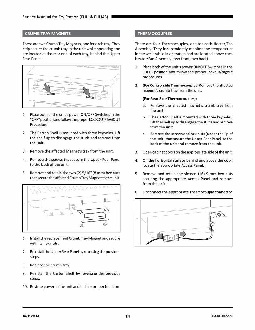
crUmB trAy mAgnetS
There are two Crumb Tray Magnets, one for each tray. They help secure the crumb tray in the unit while operating and are located at the rear end of each tray, behind the Upper Rear Panel.
1. Place both of the unit’s power ON/OFF Switches in the “OFF” position and follow the proper LOCKOUT/TAGOUT Procedure.
2. The Carton Shelf is mounted with three keyholes. Lift the shelf up to disengage the studs and remove from the unit.
3. Remove the affected Magnet’s tray from the unit.
4. Remove the screws that secure the Upper Rear Panel to the back of the unit.
5. Remove and retain the two (2) 5/16" (8 mm) hex nuts that secure the affected Crumb Tray Magnet to the unit.
6. Install the replacement Crumb Tray Magnet and secure with its hex nuts.
7. Reinstall the Upper Rear Panel by reversing the previous steps.
8. Replace the crumb tray.
9. Reinstall the Carton Shelf by reversing the previous steps.
10. Restore power to the unit and test for proper function.
ThERMOCOuPLES
There are four Thermocouples, one for each Heater/Fan Assembly. They independently monitor the temperature in the wells while in operation and are located above each Heater/Fan Assembly (two front, two back).
1. Place both of the unit’s power ON/OFF Switches in the “OFF” position and follow the proper lockout/tagout procedures.
2. (For Control side Thermocouples) Remove the affected magnet’s crumb tray from the unit.
(For Rear Side Thermocouples):
a. Remove the affected magnet’s crumb tray from the unit.
b. The Carton Shelf is mounted with three keyholes. Lift the shelf up to disengage the studs and remove from the unit.
c. Remove the screws and hex nuts (under the lip of the unit) that secure the Upper Rear Panel to the back of the unit and remove from the unit.
3. Open cabinet doors on the appropriate side of the unit.
4. On the horizontal surface behind and above the door, locate the appropriate Access Panel.
5. Remove and retain the sixteen (16) 9 mm hex nuts securing the appropriate Access Panel and remove from the unit.
6. Disconnect the appropriate Thermocouple connector.

Service Manual for Fry Station (FHU & FHUAS)
15SM-BK-FR-0004 10/31/2016
7. Remove and retain the two (2) 3/8” hex nuts securing the Thermocouple switch guard and remove from unit.
8. Compress the bracket to release the tension and carefully pull out the effected Thermocouple. NOTE: it is not necessary to remove the bracket.
9. Insert the replacement Thermocouple into the bracket. Make sure the Thermocouple extends 1-1/8" (28.6 mm) above the panel.
10. Reinstall Thermocouple switch guard with its hex nuts.
11. Reconnect the Thermocouple connector.
12. Reinstall the Access Panel.
IMPORTANT: Access Panels must be reinstalled correctly to ensure proper air flow to the product.
13. Replace the crumb tray; and if removed, the Upper Rear Panel and Carton Shelf.
14. Restore power to the unit and test for proper function.
hEATER/FAN ASSEMBLIES (CONTROL SIDE)
There are two control side Heater/Fan Assemblies, one for each side of the unit. They provide heated air flow over the products while operating and are located behind the Control Compartment.
1. Place both of the unit’s power ON/OFF Switches in the “OFF” position and follow the proper LOCKOUT/TAGOUT Procedure.
2. Remove and retain the screws securing the Control Panel to the Control Compartment.
3. Tilt the Control Panel down and away from unit far enough to access the wiring harnesses and components.
NOTE: Removing the crumb trays will allow for greater access.
4. Disconnect all molex plugs.
5. Cut all zip ties to release the compartment wires.
6. Mark and disconnect line voltage and ground wires to the terminal block.
7. Mark and disconnect the Thermocouple wires.
8. Remove and retain the four (4) bushing covers (two towards each end).
9. Remove and retain the eight (8) screws along the bottom of the black rail that secures the black rail to the unit and Control Compartment.
10. Slide out the black rail that supports and holds the Control Compartment in the unit.
11. Remove the Control Compartment from the unit. If necessary, use partially opened cabinet doors as a place to help support it.
12. Remove the four (4) screws securing the Fan Base to the unit.
13. Slide the Heater/Fan Assembly with its Fan Base out enough to access electrical connections.

Service Manual for Fry Station (FHU & FHUAS)
16 SM-BK-FR-000410/31/2016
14. Depending on Heater model:
a. (Coil-style Heater) Mark and disconnect the two (2) fan molex plugs and four (4) heater spade terminals.
b. (Calrod-style Heater) Mark and disconnect the two (2) fan molex plugs, two (2) heater spade terminals, and two (2) High Limit Thermostat spade terminals.
15. Remove the Heater/Fan Assembly from the unit.
16. Cut the tie wrap securing the motor guard to the affected end(s).
17. Remove and retain the screw securing the motor guard to the affected end(s).
18. Remove and retain the four (4) 11/32" (9mm) hex nuts/bolts securing the Fan Base to the assembly.
19. Remove and retain the two (2) bottom 11/32" (9mm) hex nuts/bolts holding the two (2) Heater/Fans together. May need to use a finger or screwdriver to assist in holding the hex nut.
20. With the two top hex nuts/bolts still installed, slightly separate, at an angle, the two Heater/Fans to allow for access to the two hex nuts/screws.
21. Remove and retain the remaining two (2) top 11/32" (9mm) hex nuts/screws holding the two (2) Heater/Fans together.
22. Install the replacement Heater/Fan by first reconnecting the two (2) top hex nuts/bolts securing the two Heater/Fans together, with the Heater/Fans at an angle.
NOTE: Torque to 18-20 in-lb.
23. Reinstall the bottom rear hex nut/bolt. Due to the space between the Heater/Fans, you may need to use a flathead screwdriver to hold up the hex nut while inserting and securing the bolt, then use the screwdriver as a wedge to prevent the hex nut from spinning.
NOTE 1: Torque to 18-20 in-lb.
NOTE 2: There is one empty hole that is not used.
This holeremainsempty
24. Reinstall the bottom front hex nut/bolt. Due to the space between the Heater/Fans, you may need to use a finger to hold up the hex nut while inserting and securing the bolt.
NOTE: Torque to 18-20 in-lb.

Service Manual for Fry Station (FHU & FHUAS)
17SM-BK-FR-0004 10/31/2016
25. Reinstall the reassembled Heater/Fan Assembly and fan guards into the fan base and unit by reversing the previous steps.
NOTE: it is very important that all nuts and screws are tightened to avoid rattling.
26. Insert the replacement Heater/Fan Assembly into position in the unit.
27. Reattach all previously disconnected Heater/Fan Assembly molex plugs and spade terminals.
28. Replace the Control Compartment and black rail under the Control Compartment, securing with its screws.
29. Reattach all previously disconnected Control Compartment molex plugs and spade terminals.
NOTE: The terminal block connections in the Control Compartment must be torqued to 30 in-lb.
30. Tilt the Control Panel into place and secure into place with its screws.
31. Restore power to the unit and test for proper function.
hEATER/FAN ASSEMBLIES (REAR SIDE)
There are two rear side Heater/Fan Assemblies, one for each side of the unit. They provide heated air flow over the products while operating and are located behind the Upper Rear Panel.
1. Place both of the unit’s power ON/OFF Switches in the “OFF” position and follow the proper LOCKOUT/TAGOUT Procedure.
2. The Carton Shelf is mounted with three (3) keyholes. Lift the shelf up to disengage the studs and remove from the unit.
3. Remove the screws and hex nuts (under lip of unit) that secure the Upper Rear Panel to the back of unit and remove from the unit.
4. Remove and retain the 4 screws securing the Fan Base to the unit.
5. Slide the entire Heater/Fan assembly with its Fan Base out enough to access electrical connections.
6. Depending on Heater model:
a. (Coil-style Heater) Mark and disconnect the two (2) fan molex plugs and four (4) heater spade terminals.
b. (Calrod-style Heater) Mark and disconnect the two (2) fan molex plugs, two (2) heater spade terminals, and two (2) High Limit Thermostat spade terminals.
7. Remove the Heater/Fan Assembly from the unit.
8. Cut the tie wrap securing the motor guard to the affected end(s).
9. Remove and retain the screw securing the motor guard to the affected end(s).

Service Manual for Fry Station (FHU & FHUAS)
18 SM-BK-FR-000410/31/2016
10. Remove and retain the four (4) 11/32" (9mm) hex nuts/bolts securing the Fan Base to the assembly.
11. Remove and retain the two (2) bottom 11/32" (9mm) hex nuts/bolts holding the two (2) Heater/Fans together. May need to use a finger or screwdriver to assist in holding the hex nut.
12. With the two (2) top hex nuts/bolts still installed, slightly separate, at an angle, the two (2) Heater/Fans to allow for access to the two (2) hex nuts/screws.
13. Remove and retain the remaining two (2) top 11/32" (9mm) hex nuts/screws holding the two (2) Heater/Fans together.
14. Install the replacement Heater/Fan by first reconnecting the two (2) top hex nuts/bolts securing the two (2) Heater/Fans together, with the Heater/Fans at an angle.
NOTE: Torque to 18-20 in-lb.
15. Reinstall the rear bottom hex nut/bolt. Due to the space between the Heater/Fans, you may need to use a flathead screwdriver to hold up the hex nut while inserting and securing the bolt, then use the screwdriver as a wedge to prevent the hex nut from spinning.
NOTE 1: Torque to 18-20 in-lb.
NOTE 2: There is one empty hole that is not used (see illustration).
This holeremainsempty
16. Reinstall the front bottom hex nut/bolt. Due to the space between the Heater/Fans, you may need to use a finger to hold up the hex nut while inserting and securing the bolt.
NOTE: Torque to 18-20 in-lb.
17. Reinstall the reassembled Heater/Fan Assembly and Motor Guards into the Fan Base and unit by reversing the previous steps.
NOTE: it is very important that all nuts and screws are tightened to avoid rattling.
18. Insert the replacement Heater/Fan Assembly into position in the unit.
19. Reattach all previously disconnected molex plugs and spade terminals.
20. Secure the replacement Heater/Fan Assembly in the unit with its screws.
21. Reinstall the Upper Rear Panel by reversing the previous steps.
22. Reinstall the Carton Shelf by reversing the previous steps.
23. Restore power to the unit and test for proper function.

Service Manual for Fry Station (FHU & FHUAS)
19SM-BK-FR-0004 10/31/2016
CALROD hEATERS (CONTROL SIDE)
note: this section is only applicable if calrod-style heaters are installed in the unit.
There are two control side Calrod Heaters, one for each side of the unit. They provide the heat that is blown by the Fan Assembly over the products while operating. They are attached to the Fan Assembly and are located behind the Control Compartment.
1. Place both of the unit’s power ON/OFF Switches in the “OFF” position and follow the proper LOCKOUT/TAGOUT Procedure.
2. Remove and retain the screws securing the Control Panel to the Control Compartment.
3. Tilt the Control Panel down and away from unit far enough to access the wiring harnesses and components.
NOTE: Removing the crumb trays will allow for greater access.
4. Disconnect all molex plugs.
5. Cut all zip ties to release the compartment wires.
6. Mark and disconnect line voltage and ground wires to the terminal block.
7. Mark and disconnect the Thermocouple wires.
8. Remove and retain the four (4) bushing covers (two towards each end).
9. Remove and retain the eight (8) screws along the bottom of the black rail that secures the black rail to the unit and Control Compartment.
10. Slide out the black rail that supports and holds the Control Compartment in the unit.
11. Remove the Control Compartment from the unit. If necessary, use partially opened cabinet doors as a place to help support it.
12. Remove the four (4) screws securing Fan Base to unit.
13. Slide the entire Heater/Fan Assembly, with its Fan Base, out enough to access electrical connections.
14. For the affected heater, mark and disconnect the two (2) heater spade terminals and two (2) High Limit Thermostat spade terminals.
15. Remove and retain the High Limit Thermostat, thermostat guard and jumper wire.
16. Remove and retain the four (4) screws securing the Calrod Heater to the Fan Assembly.
17. Attach the replacement Calrod Heater to the Fan Assembly with its screws.
note: it is very important that all screws are tightened to avoid rattling.
18. Apply heat transfer compound to the mounting surface of the High Limit Thermostat.
19. Reinstall the High Limit Thermostat, thermostat guard and jumper wire.
20. Insert Heater/Fan Assembly into position in the unit.
21. Reattach all previously disconnected molex plugs and spade terminals.
22. Replace the Control Compartment and black rail under the Control Compartment, securing with its screws.
23. Reattach all previously disconnected Control Compartment molex plugs and spade terminals.
NOTE: The terminal block connections in the Control Compartment must be torqued to 30 in-lb.
24. Tilt the Control Panel into place and secure into place with its screws.
25. Restore power to the unit and test for proper function.
Service Manual for Fry Station (FHU & FHUAS)
20 SM-BK-FR-000410/31/2016
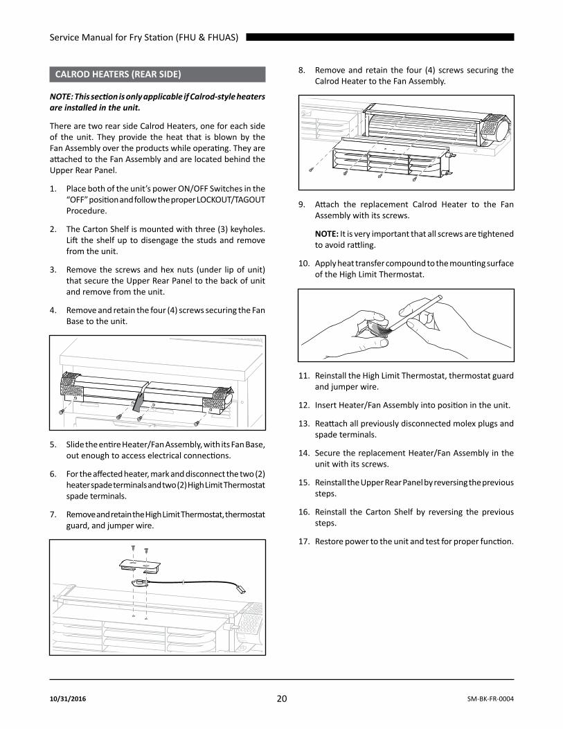
CALROD hEATERS (REAR SIDE)
note: this section is only applicable if calrod-style heaters are installed in the unit.
There are two rear side Calrod Heaters, one for each side of the unit. They provide the heat that is blown by the Fan Assembly over the products while operating. They are attached to the Fan Assembly and are located behind the Upper Rear Panel.
1. Place both of the unit’s power ON/OFF Switches in the “OFF” position and follow the proper LOCKOUT/TAGOUT Procedure.
2. The Carton Shelf is mounted with three (3) keyholes. Lift the shelf up to disengage the studs and remove from the unit.
3. Remove the screws and hex nuts (under lip of unit) that secure the Upper Rear Panel to the back of unit and remove from the unit.
4. Remove and retain the four (4) screws securing the Fan Base to the unit.
5. Slide the entire Heater/Fan Assembly, with its Fan Base, out enough to access electrical connections.
6. For the affected heater, mark and disconnect the two (2) heater spade terminals and two (2) High Limit Thermostat spade terminals.
7. Remove and retain the High Limit Thermostat, thermostat guard, and jumper wire.
8. Remove and retain the four (4) screws securing the Calrod Heater to the Fan Assembly.
9. Attach the replacement Calrod Heater to the Fan Assembly with its screws.
NOTE: It is very important that all screws are tightened to avoid rattling.
10. Apply heat transfer compound to the mounting surface of the High Limit Thermostat.
11. Reinstall the High Limit Thermostat, thermostat guard and jumper wire.
12. Insert Heater/Fan Assembly into position in the unit.
13. Reattach all previously disconnected molex plugs and spade terminals.
14. Secure the replacement Heater/Fan Assembly in the unit with its screws.
15. Reinstall the Upper Rear Panel by reversing the previous steps.
16. Reinstall the Carton Shelf by reversing the previous steps.
17. Restore power to the unit and test for proper function.

Service Manual for Fry Station (FHU & FHUAS)
21SM-BK-FR-0004 10/31/2016
FAN ASSEMBLIES (CONTROL SIDE w/CALROD hEATERS)
note: this section is only applicable if calrod-style heaters are installed in the unit.
There are two control side Fan Assemblies, one for each side of the unit. They blow the heat generated by the Calrod Heaters over the products while operating. They are attached to the Calrod Heaters and are located behind the Control Compartment.
1. Place both of the unit’s power ON/OFF Switches in the “OFF” position and follow the proper LOCKOUT/TAGOUT Procedure.
2. Remove and retain the screws securing the Control Panel to the Control Compartment.
3. Tilt the Control Panel down and away from unit far enough to access the wiring harnesses and components.
NOTE: Removing the crumb trays will allow for greater access.
4. Disconnect all molex plugs.
5. Cut all zip ties to release the compartment wires.
6. Mark and disconnect line voltage and ground wires to the terminal block.
7. Mark and disconnect the Thermocouple wires.
8. Remove and retain the four (4) bushing covers (two towards each end).
9. Remove and retain the eight (8) screws along the bottom of the black rail that secures the black rail to the unit and Control Compartment.
10. Slide out the black rail that supports and holds the Control Compartment in the unit.
11. Remove the Control Compartment from the unit. If necessary, use partially opened cabinet doors as a place to help support it.
12. Remove the four (4) screws securing the Fan Base to the unit.
13. Slide the entire Heater/Fan Assembly, with its Fan Base, out enough to access electrical connections.
14. For the affected fan, mark and disconnect the fan molex plug, two (2) heater spade terminals, and two (2) High Limit Thermostat spade terminals.
15. Remove the Heater/Fan Assembly from the unit.
16. Cut the tie wrap securing the motor guard to the affected end(s).
17. Remove and retain the screw securing the motor guard to the affected end(s).
18. Remove and retain the four (4) 11/32" (9mm) hex nuts/bolts securing the Fan Base to the assembly.
19. Remove and retain the two (2) bottom 11/32" (9mm) hex nuts/bolts holding the two (2) Heater/Fans together. May need to use a finger or screwdriver to assist in holding the hex nut.
20. With the two (2) top hex nuts/bolts still installed, slightly separate, at an angle, the two Heater/Fans to allow for access to the two hex nuts/screws.
Service Manual for Fry Station (FHU & FHUAS)
22 SM-BK-FR-000410/31/2016
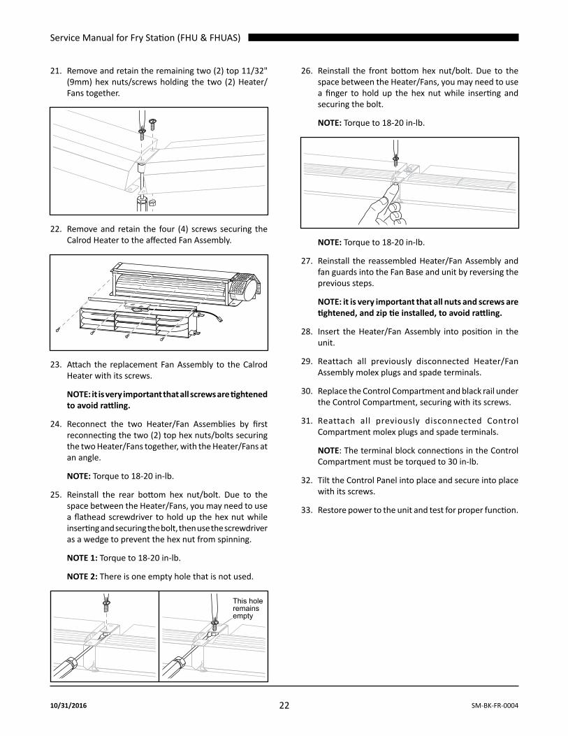
21. Remove and retain the remaining two (2) top 11/32" (9mm) hex nuts/screws holding the two (2) Heater/Fans together.
22. Remove and retain the four (4) screws securing the Calrod Heater to the affected Fan Assembly.
23. Attach the replacement Fan Assembly to the Calrod Heater with its screws.
note: it is very important that all screws are tightened to avoid rattling.
24. Reconnect the two Heater/Fan Assemblies by first reconnecting the two (2) top hex nuts/bolts securing the two Heater/Fans together, with the Heater/Fans at an angle.
NOTE: Torque to 18-20 in-lb.
25. Reinstall the rear bottom hex nut/bolt. Due to the space between the Heater/Fans, you may need to use a flathead screwdriver to hold up the hex nut while inserting and securing the bolt, then use the screwdriver as a wedge to prevent the hex nut from spinning.
NOTE 1: Torque to 18-20 in-lb.
NOTE 2: There is one empty hole that is not used.
This holeremainsempty
26. Reinstall the front bottom hex nut/bolt. Due to the space between the Heater/Fans, you may need to use a finger to hold up the hex nut while inserting and securing the bolt.
NOTE: Torque to 18-20 in-lb.
NOTE: Torque to 18-20 in-lb.
27. Reinstall the reassembled Heater/Fan Assembly and fan guards into the Fan Base and unit by reversing the previous steps.
NOTE: it is very important that all nuts and screws are tightened, and zip tie installed, to avoid rattling.
28. Insert the Heater/Fan Assembly into position in the unit.
29. Reattach all previously disconnected Heater/Fan Assembly molex plugs and spade terminals.
30. Replace the Control Compartment and black rail under the Control Compartment, securing with its screws.
31. Reattach all previously disconnected Control Compartment molex plugs and spade terminals.
NOTE: The terminal block connections in the Control Compartment must be torqued to 30 in-lb.
32. Tilt the Control Panel into place and secure into place with its screws.
33. Restore power to the unit and test for proper function.

Service Manual for Fry Station (FHU & FHUAS)
23SM-BK-FR-0004 10/31/2016
FAN ASSEMBLIES (REAR SIDE w/CALROD hEATERS)
note: this section is only applicable if calrod-style heaters are installed in the unit.
There are two rear side Fan Assemblies, one for each side of the unit. They blow the heat generated by the Calrod Heaters over the products while operating. They are attached to the Calrod Heaters and are located behind the Upper Rear Panel.
1. Place both of the unit’s power ON/OFF Switches in the “OFF” position and follow the proper LOCKOUT/TAGOUT Procedure.
2. The Carton Shelf is mounted with three (3) keyholes. Lift the shelf up to disengage the studs and remove from the unit.
3. Remove the screws and hex nuts (under lip of unit) that secure the Upper Rear Panel to the back of unit and remove from the unit.
4. Remove and retain the four (4) screws securing the Fan Base to the unit.
5. Slide the entire Heater/Fan Assembly with its Fan Base out enough to access electrical connections.
6. Mark and disconnect the two (2) fan molex plugs, two (2) heater spade terminals, and two (2) High Limit Thermostat spade terminals.
7. Remove the Heater/Fan Assembly from the unit.
8. Cut the tie wrap securing the motor guard to the affected end(s).
9. Remove and retain the screw securing the motor guard to the affected end(s).
10. Remove and retain the four (4) 11/32” (9mm) hex nuts/bolts securing the Fan Base to the assembly.
11. Remove and retain the two (2) bottom 11/32” (9mm) hex nuts/bolts holding the two (2) Heater/Fans together. May need to use a finger or screwdriver to assist in holding the hex nut.
12. With the two (2) top hex nuts/bolts still installed, slightly separate, at an angle, the two (2) Heater/Fans to allow for access to the two (2) hex nuts/screws.
13. Remove and retain the remaining two (2) top 11/32” (9mm) hex nuts/screws holding the two (2) Heater/Fans together.
14. Remove and retain the four (4) screws securing the Calrod Heater to the affected Fan Assembly.

Service Manual for Fry Station (FHU & FHUAS)
24 SM-BK-FR-000410/31/2016
15. Attach the replacement Fan Assembly to the Calrod Heater with its screws.
note: it is very important that all screws are tightened to avoid rattling.
16. Reconnect the two Heater/Fan Assemblies by first reconnecting the two (2) top hex nuts/bolts securing the two Heater/Fans together, with the Heater/Fans at an angle.
NOTE: Torque to 18-20 in-lb.
17. Reinstall the rear bottom hex nut/bolt. Due to the space between the Heater/Fans, you may need to use a flathead screwdriver to hold up the hex nut while inserting and securing the bolt, then use the screwdriver as a wedge to prevent the hex nut from spinning.
NOTE 1: Torque to 18-20 in-lb.
NOTE 2: There is one empty hole that is not used.
This holeremainsempty
18. Reinstall the front bottom hex nut/bolt. Due to the space between the Heater/Fans, you may need to use a finger to hold up the hex nut while inserting and securing the bolt.
NOTE: Torque to 18-20 in-lb.
19. Reinstall the reassembled Heater/Fan Assembly and motor guards into the Fan Base and unit by reversing the previous steps.
NOTE: it is very important that all nuts and screws are tightened, and zip tie installed, to avoid rattling.
20. Insert the Heater/Fan Assembly into position in the unit.
21. Reattach all previously disconnected molex plugs and spade terminals.
22. Secure the Heater/Fan Assembly in the unit with its screws.
23. Reinstall the Upper Rear Panel by reversing the previous steps.
24. Reinstall the Carton Shelf by reversing the previous steps.
25. Restore power to the unit and test for proper function.

Service Manual for Fry Station (FHU & FHUAS)
25SM-BK-FR-0004 10/31/2016
HigH limit tHermoStAtS (CONTROL SIDE w/CALROD-STyLE hEATER)
note: this section is only applicable if calrod-style heaters are installed in the unit.
There are two control side High Limit Thermostats, one for each side of the unit. They monitor the Calrod Heater temperature and serve as a circuit interrupter in case of Calrod Heater overheating. They are attached to each Calrod Heater behind the Control Compartment.
1. Place both of the unit’s power ON/OFF Switches in the “OFF” position and follow the proper LOCKOUT/TAGOUT Procedure.
2. Remove and retain the screws securing the Control Panel cover to the Control Compartment.
3. Tilt the Control Panel down and away from unit far enough to access the wiring harnesses and components.
NOTE: Removing the crumb trays will allow for greater access.
4. Disconnect all molex plugs.
5. Cut all zip ties to release the compartment wires.
6. Mark and disconnect line voltage and ground wires to the terminal block.
7. Mark and disconnect the Thermocouple wires.
8. Remove and retain the four (4) bushing covers (two towards each end).
9. Remove and retain the eight (8) screws along the bottom of the black rail that secures the black rail to the unit and Control Compartment.
10. Slide out the black rail that supports and holds the Control Compartment in the unit.
11. Remove the Control Compartment from the unit. If necessary, use partially opened cabinet doors as a place to help support it.
12. Remove the four (4) screws securing the Fan Base to the unit.
13. Slide the entire Heater/Fan Assembly, with its Fan Base, out enough to access the High Limit Thermostat.
14. Mark and disconnect the two (2) spade terminals to the affected High Limit Thermostat(s).
15. Remove the affected High Limit Thermostat(s), retain the Thermostat guard(s) and clean the mounting surface of any residual heat transfer compound.
16. Apply heat transfer compound to the mounting surface of the replacement High Limit Thermostat(s).
17. Attach the replacement High Limit Thermostat(s) and Thermostat guards to Calrod Heater(s) with its screws.
note: it is very important that all screws are tightened to avoid rattling.
18. Insert Heater/Fan Assembly into position in the unit.
19. Reattach all previously disconnected molex plugs, spade terminals, and jumper wire.
20. Replace the Control Compartment and black rail under the Control Compartment, securing with its screws.
21. Reattach all previously disconnected Control Compartment molex plugs and spade terminals.
NOTE: The terminal block connections in the Control Compartment must be torqued to 30 in-lb.
22. Tilt the Control Panel into place and secure into place with its screws.
23. Restore power to the unit and test for proper function.

Service Manual for Fry Station (FHU & FHUAS)
26 SM-BK-FR-000410/31/2016
HigH limit tHermoStAtS (REAR SIDE w/CALROD-STyLE hEATER)
note: this section is only applicable if calrod-style heaters are installed in the unit.
There are two rear side High Limit Thermostats, one for each side of the unit. They monitor the Calrod Heater temperature and serve as a circuit interrupter in case of Calrod Heater overheating. They are attached to each Calrod Heater behind the Upper Rear Panel.
1. Place both of the unit’s power ON/OFF Switches in the “OFF” position and follow the proper LOCKOUT/TAGOUT Procedure.
2. The Carton Shelf is mounted with three (3) keyholes. Lift the shelf up to disengage the studs and remove from the unit.
3. Remove the screws and hex nuts (under lip of unit) that secure the Upper Rear Panel to the back of unit and remove from the unit.
4. Remove and retain the four (4) screws securing the Fan Base to the unit.
5. Slide the entire Heater/Fan Assembly, with its Fan Base, out enough to access the High Limit Thermostat.
6. Mark and disconnect the two (2) spade terminals to the affected High Limit Thermostat(s).
7. Remove the affected High Limit Thermostat(s), retain the Thermostat guard(s) and clean the mounting surface of any residual heat transfer compound.
8. Apply heat transfer compound to the mounting surface of the replacement High Limit Thermostat(s).
9. Attach the replacement High Limit Thermostat(s) and Thermostat guard(s) to the Calrod Heater(s) with its screws.
note: it is very important that all screws are tightened to avoid rattling.
10. Insert Heater/Fan Assembly into position in the unit.
11. Reattach all previously disconnected spade terminals.
12. Secure Heater/Fan Assembly in the unit with its screws.
13. Reinstall the Upper Rear Panel by reversing the previous steps.
14. Reinstall the Carton Shelf by reversing the previous steps.
15. Restore power to the unit and test for proper function.

Service Manual for Fry Station (FHU & FHUAS)
27SM-BK-FR-0004 10/31/2016
FhuAS ELECTRICAL COMPONENTS
POwER ON/OFF SwITChES
There are two (2) Power ON/OFF Switches, located on the Front Housing panel.
TOOLS REQUIRED: Phillips screwdriver
1. Place both of the unit’s Power ON/OFF Switches in the “OFF” position and follow the proper lockout/tagout procedures.
2. Remove and retain the four (4) screws securing the Front Housing panel to the unit.
3. Slide down and tilt out the Front Housing panel away from unit.
NOTE: The Front Housing panel is attached to the unit with two (2) 8-inch lanyards that are designed to support the weight of the panel. These do not need to be removed for these instructions.
4. Mark and disconnect the four (4) spade terminals to the affected Power ON/OFF Switch.
5. The Power ON/OFF Switch is secured to the Front Housing with spring clips. Depress the spring clips and slide the switch from the Front Housing.
RESTORE:
6. Install the replacement Power ON/OFF Switch by sliding it into its position in the Front Housing panel until secured with its spring clips.
7. Reattach the Power ON/OFF Switch spade terminals.
8. Replace the Front Housing by tilting the panel inward and lifting up and securing with its screws.
9. Restore power to the unit and test for proper function.

Service Manual for Fry Station (FHU & FHUAS)
28 SM-BK-FR-000410/31/2016
CAPACITORS
There are two (2) Capacitors, one for each fan. They are located directly behind the Front Housing panel, attached to the Fan Bracket on the front of the Heater/Fan Assembly. It is used to keep the Fan running more efficiently.
TOOLS REQUIRED: Phillips screwdriver, 1/2-inch wrench
1. Place both of the unit’s Power ON/OFF Switches in the “OFF” position and follow the proper lockout/tagout procedures.
2. Remove and retain the four (4) screws securing the Front Housing panel to the unit.
3. Slide down and tilt out the Front Housing away from unit.
NOTE: The Front Housing panel is attached to the unit with two (2) 8-inch lanyards that are designed to support the weight of the panel. These do not need to be removed for these instructions.
4. Remove and retain the single screw securing the Capacitor Bracket to the Fan Bracket.
5. Mark and disconnect the affected Capacitor’s two (2) power wires from its wiring harness.
6. Safely discharge the capacitor.
7. Using a 1/2-inch wrench, remove and retain the 1/2-inch hex nut securing the affected Capacitor to the Capacitor Bracket.
RESTORE:
8. Install the replacement Capacitor to the Capacitor Bracket by securing it with its hex nut.
9. Reattach the Capacitor wires to its wiring harness.
10. Secure the Capacitor Bracket to the Fan Bracket with its screw.
11. Replace the Front Housing by tilting the panel inward and lifting up and securing with its screws.
12. Restore power to the unit and test for proper function.

Service Manual for Fry Station (FHU & FHUAS)
29SM-BK-FR-0004 10/31/2016
FANS
There are two (2) Fans, one for each side (channel) of the unit. They are part of the Return Box Assembly, directly behind the Front Housing panel. They blow the heat generated by the Heaters over the products while operating.
TOOLS REQUIRED: Phillips screwdriver; precision screwdriver; 11/32-inch Nut Driver; Flathead Screwdriver, zip ties
1. Place both of the unit’s Power ON/OFF Switches in the “OFF” position and follow the proper lockout/tagout procedures.
2. Remove and retain the four (4) screws securing the Front Housing panel to the unit.
3. Slide down and tilt out the Front Housing away from unit.
NOTE: The Front Housing panel is attached to the unit with two (2) 8-inch lanyards that are designed to support the weight of the panel. These do not need to be removed for these instructions.
4. Remove and retain the single screw securing the Capacitor Bracket to the Fan Bracket.
5. Remove the two (2) screws securing the Fan Bracket to the unit.
6. Carefully slide the entire Heater/Fan Assembly out enough to access its electrical connections.
NOTE: It will be easier to disconnect the entire Heater/Fan Assembly in order to successfully remove and replace a fan.
7. At each end of the Heater/Fan Assembly, note the location of and then cut the existing tie wraps, then mark and disconnect the black (High Limit Thermostat), white (Heater), and Fan (black with 5 separate leads) from their power harnesses. The fan leads are secured to its harness with a small precision screwdriver.
8. Remove the Heater/Fan Assembly from the unit.
9. At each end of the Heater/Fan Assembly, remove and retain the two (2) 11/32-inch hex nuts securing each Fan Bracket and Motor Guard to the Heater/Fan Assembly.

Service Manual for Fry Station (FHU & FHUAS)
30 SM-BK-FR-000410/31/2016
10. Remove and retain the two (2) bottom 11/32-inch hex nuts/bolts holding the two (2) Heater/Fans together. It may be required to use a finger or tool to assist in holding the hex nut.
11. With the two (2) top hex nuts/bolts still installed, slightly separate, at an angle, the two (2) Heater/Fans to allow for access to the two (2) hex nuts/screws.
12. Remove and retain the remaining two (2) top 11/32-inch hex nuts/screws holding the two (2) Heater/Fans together.
13. Remove and retain the four (4) screws securing the Calrod Heater to the affected Fan.
RESTORE:
14. Attach the replacement Fan to the Calrod Heater with its screws.
note: it is very important that all screws are tightened to avoid rattling.
15. Reconnect the two (2) Heater/Fan Assemblies by first reconnecting the two (2) top hex nuts/bolts securing the two (2) Heater/Fans together, with the Heater/Fans at an angle.
NOTE: Torque to 18-20 in-lb.
16. Reinstall the front bottom hex nut/bolt. Due to the space between the Heater/Fans, you may need to use a flathead screwdriver to hold up the hex nut while inserting and securing the bolt, then use the screwdriver as a wedge to prevent the hex nut from spinning.
NOTE 1: Torque to 18-20 in-lb.
NOTE 2: There is one empty hole that is not used.
This holeremainsempty
17. Reinstall the rear bottom hex nut/bolt. Due to the space between the Heater/Fans, you may need to use a finger to hold up the hex nut while inserting and securing the bolt.
NOTE: Torque to 18-20 in-lb.
18. Reinstall the reassembled Heater/Fan Assembly to the Fan Bracket and Motor Guard by reversing the previous steps.
NOTE: It is very important that all nuts and screws are tightened and the zip tie is reinstalled to avoid rattling.

Service Manual for Fry Station (FHU & FHUAS)
31SM-BK-FR-0004 10/31/2016
19. Reattach the Fan, Heater, and High Limit Thermostat wires to their respective wiring harnesses.
20. Carefully insert the Heater/Fan Assembly into position in the unit.
21. Reinstall the two (2) screws securing the Fan Bracket to the unit.
22. Secure the Capacitor Bracket to the Fan Bracket with its screw.
23. Replace the Front Housing by tilting the panel inward and lifting up and securing with its screws.
24. Restore power to the unit and test for proper function.
hEATERS
There are two (2) Heaters, one for each side (channel) of the unit. They are part of the Return Box Assembly, directly behind the Front Housing panel. They generate the heat that is blown by the Fan over the products while operating.
TOOLS REQUIRED: Phillips screwdriver; Heat Transfer compound
1. Place both of the unit’s Power ON/OFF Switches in the “OFF” position and follow the proper lockout/tagout procedures.
2. Remove and retain the four (4) screws securing the Front Housing panel to the unit.
3. Slide down and tilt out the Front Housing away from unit.
NOTE: The Front Housing panel is attached to the unit with two (2) 8-inch lanyards that are designed to support the weight of the panel. These do not need to be removed for these instructions.

Service Manual for Fry Station (FHU & FHUAS)
32 SM-BK-FR-000410/31/2016
4. Remove and retain the single screw securing the Capacitor Bracket to the Fan Bracket.
5. Remove the two (2) screws securing the Fan Bracket to the unit.
6. Carefully slide the entire Heater/Fan Assembly out enough to access its electrical connections.
NOTE: It is not required, but perfectly OK, if desired, to remove the entire Heater/Fan Assembly from the unit.
7. At the end of the Heater/Fan Assembly with the affected Heater, note the location of and cut any necessary tie wraps; then mark and disconnect the white (Heater) power wires, the two (2) heater spade terminals, and two (2) High Limit Thermostat spade terminals.
8. Remove and retain the High Limit Thermostat, thermostat guard, and jumper wire from the affected Heater.
9. Remove and retain the four (4) screws securing the Heater to the Fan.
RESTORE:
10. Attach the replacement Heater to the Fan with its screws.
note: it is very important that all screws are tightened to avoid rattling.
11. After applying heat transfer compound to the High Limit Thermostat, reattach the High Limit Thermostat, thermostat guard, and jumper wire to the replacement Heater.
12. Reattach the Fan, Heater, and High Limit Thermostat wires to their respective wiring harnesses.
13. Carefully reinsert the Heater/Fan Assembly into position in the unit.
14. Reinstall the two (2) screws securing the Fan Bracket to the unit.
15. Secure the Capacitor Bracket to the Fan Bracket with its screw.
16. Replace the Front Housing by tilting the panel inward and lifting up and securing with its screws.
17. Restore power to the unit and test for proper function.

Service Manual for Fry Station (FHU & FHUAS)
33SM-BK-FR-0004 10/31/2016
HigH limit tHermoStAtS
There are two (2) High Limit Thermostats, one for each side (channel) of the unit. They are attached to top of each Heater as part of the Return Box Assembly. They monitor the Heater temperature and serve as a circuit interrupter in case of Heater overheating.
TOOLS REQUIRED: Phillips screwdriver, Heat Transfer compound
1. Place both of the unit’s Power ON/OFF Switches in the “OFF” position and follow the proper lockout/tagout procedures.
2. Remove and retain the four (4) screws securing the Front Housing panel to the unit.
3. Slide down and tilt out the Front Housing away from unit.
NOTE: The Front Housing panel is attached to the unit with two (2) 8-inch lanyards that are designed to support the weight of the panel. These do not need to be removed for these instructions.
4. Remove and retain the single screw securing the Capacitor Bracket to the Fan Bracket.
5. Remove the two (2) screws securing the Fan Bracket to the unit.
6. Carefully slide the entire Heater/Fan Assembly out enough to access its electrical connections.
NOTE: It will be easier to disconnect the entire Heater/Fan Assembly in order to successfully remove and replace a fan.
7. Mark and disconnect the two (2) spade terminals to the affected High Limit Thermostat.
8. Remove the affected High Limit Thermostat and its thermostat guard and clean the mounting surface of any residual heat transfer compound.

Service Manual for Fry Station (FHU & FHUAS)
34 SM-BK-FR-000410/31/2016
RESTORE:
9. Apply heat transfer compound to the mounting surface of the replacement High Limit Thermostat.
10. Attach the replacement High Limit Thermostat and thermostat guards to the Heater with its screws.
note: it is very important that all screws are tightened to avoid rattling.
11. Reattach all previously disconnected spade terminals.
12. Carefully reinsert the Heater/Fan Assembly into position in the unit.
13. Reinstall the two (2) screws securing the Fan Bracket to the unit.
14. Secure the Capacitor Bracket to the Fan Bracket with its screw.
15. Replace the Front Housing by tilting the panel inward and lifting up and securing with its screws.
16. Restore power to the unit and test for proper function.

Service Manual for Fry Station (FHU & FHUAS)
35SM-BK-FR-0004 10/31/2016
FHU ProgrAmming inStrUctionSThe control contains 4 recipes (r1, r2, r3, and r4), each recipe contains 28 parameters. The parameters in each recipe (Default recipe = r1) can be viewed and/or changed via the control keys:
Down
Temperature
Time
Up
ProgrAmming AnD DiSPlAying PArAmeterS (FoUr reciPeS)
1. Upon power-up, the display will briefly show the model and version number of the control. After this short display, the control will then display “IdLE” indicating that the control is running in idle mode of the current default recipe or static condition.
2. From “IdLE” press and hold the “Temperature” and “Up” keys for 10 seconds.
Display will then show the current temperatures.
3. Enter program mode by pressing and holding the “Temp” key for 5 seconds.
The display then indicates the currently selected recipe.
a. Example: When the current recipe is 2, the display shows “r 2” flashing.
b. The current recipe can be changed by pressing the “Up” or “Down” key.
c. The parameters for the selected recipe can then be viewed and changed.
4. Pressing the “Temp” key steps through the parameters.

Service Manual for Fry Station (FHU & FHUAS)
36 SM-BK-FR-000410/31/2016
a. Change a parameter by pressing the “Up” or “Down” key.
Parameters are displayed flashing in the order shown in the table at the end of this section.
b. Zones will be indicated by flashing the heat LED as it currently does (one quick flash for zone 1 and two quick flashes for zone 2).
c. While displaying offset temperatures, digit 2 and 3 decimal points will illuminate.
d. While displaying idle parameters, all 4 decimal points will illuminate.
e. While displaying stage 1, only digit 1 (far left) decimal point will illuminate.
f. While displaying stage 2, digit 2 decimal point will illuminate.
g. While displaying stage 3, digit 3 decimal point will illuminate.
h. While displaying stage 4, digit 4 decimal point will illuminate.
i. The decimal point indicators will not flash to help avoid misinterpretation.
j. The speed parameters will be in 1% increments from 0 to 100. Values will be stored when stepping to the next item.
k. Stepping after the last item will go back to the current recipe number display. One can then select a new recipe for viewing or changing.
l. Exit the program mode at any time by pressing the “Time” key.
NOTE: The recipe just displayed or changed will be the active recipe.

Service Manual for Fry Station (FHU & FHUAS)
37SM-BK-FR-0004 10/31/2016
Other changes:
A. When changing a parameter, the flashing will stop and restart 1 second after last change.
B. There is a second acceleration (at least 10X faster) when holding the up or down key for setting a parameter. The second acceleration takes place after 5 seconds of initial acceleration.
C. The “Dual Heater Staged Cooking EEPROM Setup Utility” has been updated to incorporate the 4 recipes above.
ProgrAmming PArAmeterS
Item Zone/Stage LED Display Allowable Range Default
1. Zone 1 Max Fan Speed S L 7 0 0 – 99% 70%
2. Zone 2 Max Fan Speed S L 7 0 0 – 99% 70%
3. Zone 1 temperature offset _ _.0.˙F 0°F – 150°F 0
4. Zone 2 temperature offset _ _.0.˙F 0°F – 150°F 0
5. Zone 1 idle temperature set point 1.9.5.˙F. 100°F – 250°F 195°F
6. Zone 1 idle fan speed S._.5.0. 0 – 100% 50%
7. Zone 2 idle temperature set point 1.9.5.˙F. 100°F – 250°F 195°F
8. Zone 2 idle fan speed S._.5.0. 0 – 100% 50%
9. Stage 1 time _.0:1 4 * 0 min – 9h:59m 14 min
10. Stage 1 Zone 1 temperature set point 1.9 5˙F 100°F – 250°F 195°F
11. Stage 1 Zone 1 fan speed S._.5.0 0 – 100% 50%
12. Stage 1 Zone 2 temperature set point 1.9 5˙F 100°F – 250°F 195°F
13. Stage 1 Zone 2 fan speed S._.5.0 0 – 100% 50%
14. Stage 2 time _0.:0 0 * 0 min – 9h:59m 0
15. Stage 2 Zone 1 temperature set point 1 0.0˙F 100°F – 250°F 100°F
16. Stage 2 Zone 1 fan speed S_. 5 0 0 – 100% 50%
17. Stage 2 Zone 2 temperature set point 1 0.0˙F 100°F – 250°F 100°F
18. Stage 2 Zone 2 fan speed S_. 5 0 0 – 100% 50%
19. Stage 3 time _0:0.0 * 0 min – 9h:59m 0
20. Stage 3 Zone 1 temperature set point 1 0 0.˙F 100°F – 250°F 100°F
21. Stage 3 Zone 1 fan speed S_ 5.0 0 – 100% 50%
22. Stage 3 Zone 2 temperature set point 1 0 0.˙F 100°F – 250°F 100°F
23. Stage 3 Zone 2 fan speed S_ 5.0 0 – 100% 50%
24. Stage 4 time _0:0 0. * 0 min – 9h:59m 0
25. Stage 4 Zone 1 temperature set point 1 0 0˙F. 100°F – 250°F 100°F
26. Stage 4 Zone 1 fan speed S_ 5 0. 0 – 100% 50%
27. Stage 4 Zone 2 temperature set point 1 0 0˙F. 100°F – 250°F 100°F
28. Stage 4 Zone 2 fan speed S_ 5 0 0 – 100% 50%
* The total time for stages 1 thru 4 is 9hr:59min. When entering a time, the max time for a stage will be limited by the sum. For example, if stage 1 is 5 hours, and stages 3 and 4 are 0; when entering time into stage 2, the time will top out at 4hr:59min, then go to 0.

Service Manual for Fry Station (FHU & FHUAS)
38 SM-BK-FR-000410/31/2016
FHU troUBleSHootingPROBLEM POSSIBLE CAuSE SOLuTION
Switches ON, No Display or Lights Both Zones
No Power to Unit Check Supply Breaker
Faulty Wiring Repair Faulty Wiring
Switch ON, Switch Lit, No Display, One Zone
Faulty Power Relay Replace Relay
Faulty Wiring Repair Faulty Wiring
Faulty Power Switch Replace Switch
Crumb Tray not in Place Insert Crumb Tray Fully
Faulty Interlock Switch Replace Interlock Switch
Faulty Controller Replace Controller
No Heat, Controller Calling for Heat, One Zone, Front or Rear
Faulty Heat Relay Replace Relay
Faulty Fan/Heater Replace Fan/Heater
Faulty Wiring Repair Faulty Wiring
Faulty Thermocouple Replace Thermocouple
No Heat, Controller Calling for Heat, One Zone, Both Front and Rear Faulty Controller Replace Controller
No Blower, Controller Calling for Heat, One Zone, Front or Rear
Faulty Wiring Repair Faulty Wiring
Faulty Fan/Heater Replace Fan/Heater
No Blower, Controller Calling for Heat, One Zone, Both Front and Rear
Faulty 24V PC Power Board Replace 24V PC Power Board
Faulty Wiring Repair Faulty Wiring
Faulty Controller Replace Controller
Cooling Fan not TurningFaulty Cooling Fan Replace Cooling Fan
Faulty Wiring Repair Faulty Wiring
Temperature too High
Faulty Heat Relay Replace Relay
Faulty Controller Replace Controller
Faulty Thermocouple Replace Thermocouple
Temperature too Low
Faulty Heat Relay Replace Relay
Faulty Controller Replace Controller
Faulty Thermocouple Replace Thermocouple

Service Manual for Fry Station (FHU & FHUAS)
39SM-BK-FR-0004 10/31/2016
FHU troUBleSHooting gUiDe
FHUAS troUBleSHooting gUiDe

Service Manual for Fry Station (FHU & FHUAS)
40 SM-BK-FR-000410/31/2016
wiring DiAgrAmSFhu-2 with CALROD hEATERS (229818)

Service Manual for Fry Station (FHU & FHUAS)
41SM-BK-FR-0004 10/31/2016
Fhu-2 with COIL hEATERS (229818)

Service Manual for Fry Station (FHU & FHUAS)
42 SM-BK-FR-000410/31/2016
Fhu-1 with COIL hEATER (229817)

Service Manual for Fry Station (FHU & FHUAS)
43SM-BK-FR-0004 10/31/2016
Fhu-1 with CALROD hEATER (229817)-

Service Manual for Fry Station (FHU & FHUAS)
44 SM-BK-FR-000410/31/2016
Fhu-2 with COIL hEATERS, FOR EMEA (229836)

Service Manual for Fry Station (FHU & FHUAS)
45SM-BK-FR-0004 10/31/2016
ELECTRICAL ChASE
Fhu-2 ELECTRICAL ChASE, INLINE (229935, Rev. D)
Fhu-2 ELECTRICAL ChASE, STANDALONE (229938, Rev. B)
MARGAID GNIRIW ESAHC LACIRTCELE NOITATS YRF
:.ON TRAP / GWD
1 FO 1 TEEHS
ETADYB GNIWARD
LAIRETAM
HSINIF:ELIF TRAP
58.0:1 ELACS
SIHT NI DENIATNOC NOITAMROFNI EHT FO YTREPORP ELOS EHT SI GNIWARD
NOITCUDORPER YNA .OC .GFM EKUDNETTIRW TUOHTIW ELOHW RO TRAP NI
.DETIBIHORP SI NOISSIMREP
VER #OCE YB VER ETAD NOITPIRCSED
A - WEB 31-61-5 MARGAID WENB - WJK 31-91-7 STHGIL FLEHS UHP DEDDAC - WEJ 31-31-8 SRETAEH & STHGIL ROF SEHCTIWS DEDDAD WJK 31/01/9 PMA 51 OT REKAERB SHRI DEGNAHC-
MARGAID GNIRIWEWB 31/61/50ESAHC .CELE NOITATS YRF
1# NI
AM
2# NI
AM
D V
ER 539922
N/P
000.4
000.8
NOITATS YRF
SRETAEH
ROTAREGIRFER
SHRI
EVAWORCIM
3L
2L
1L
1#
2#
G
N
3L
2L
1L
N
G
P2 A05
P1 A01
P1 A51
TFELLANIMRET
KCOLB
1 2 3 4 G
P2 A51
P2 A02THGIR
LANIMRETKCOLB
539922
:SETON
DERIUQER SA :YTQ 847912 :N/P DES RALYM REVLIS EDIW "4.1DERIUQER SA :YTQ 657912 :N/P DES NOBBIR RETNIRP NOBRAC.2
FLEHS SHRISTHGIL
YLPPA GNIWOLLOF EHT LLA:DETON ESIWREHTO SSELNU
LYNIV DNA NOITCERID NIARG LACITIRC TON ERA EDIS
EDISTUO ERA SNOISNEMID LLA:SECNARELOT
"230. -\+ RAENIL 1 -\+ SELGNA
SELOH "200. -\+
539922
.OC GNIRUTCAFUNAM EKUD10356 .OM AILADES EVIRD EKUD 106
"RENTRAP SNOITULOS RUOY"
4.000
8.000
FRY STATION
IRHS SHELF LIGHTS IRHS
L2
L1
#1
#2
G
N
L2
L1
N
G
50A 2P
10A 1P
MA
IN #
1M
AIN
#2
LEFTTERMINAL
BLOCK
1 2 3 4 G
15A 2P
RIGHTTERMINAL
BLOCK
FRY STATION STAND ALONE ELECTRICAL CHASE WIRING DIAGRAM
P/N 229938
DUKE MANUFACTURING CO.
DWG / PART NO.:
SHEET 1 OF 1
DATEDRAWING BY
ALL THE FOLLOWING APPLYUNLESS OTHERWISE NOTED:
GRAIN DIRECTION AND VINYL SIDE ARE NOT CRITICAL ALL DIMENSIONS ARE OUTSIDETOLERANCES: LINEAR +\- .032" ANGLES +\- 1 HOLES +\- .002"
MATERIAL
FINISH
WIRING DIAGRAM
229938
KJW 07/05/13
PART FILE:
FRY STATION STAND ALONE
REV ECO# REV BY DATE DESCRIPTIONA
SCALE 1:0.85
THE INFORMATION CONTAINED IN THISDRAWING IS THE SOLE PROPERTY OF DUKE MFG. CO. ANY REPRODUCTION IN PART OR WHOLE WITHOUT WRITTENPERMISSION IS PROHIBITED.
601 DUKE DRIVE SEDALIA MO. 65301"YOUR SOLUTIONS PARTNER"
B 9/19/13KJW CHANGED FRY TO SINGLE PHASE

Service Manual for Fry Station (FHU & FHUAS)
46 SM-BK-FR-000410/31/2016
Fhu-2 Electrical Chase, Inline (229935)
Fhu-2 Electrical Chase, Standalone (229938)
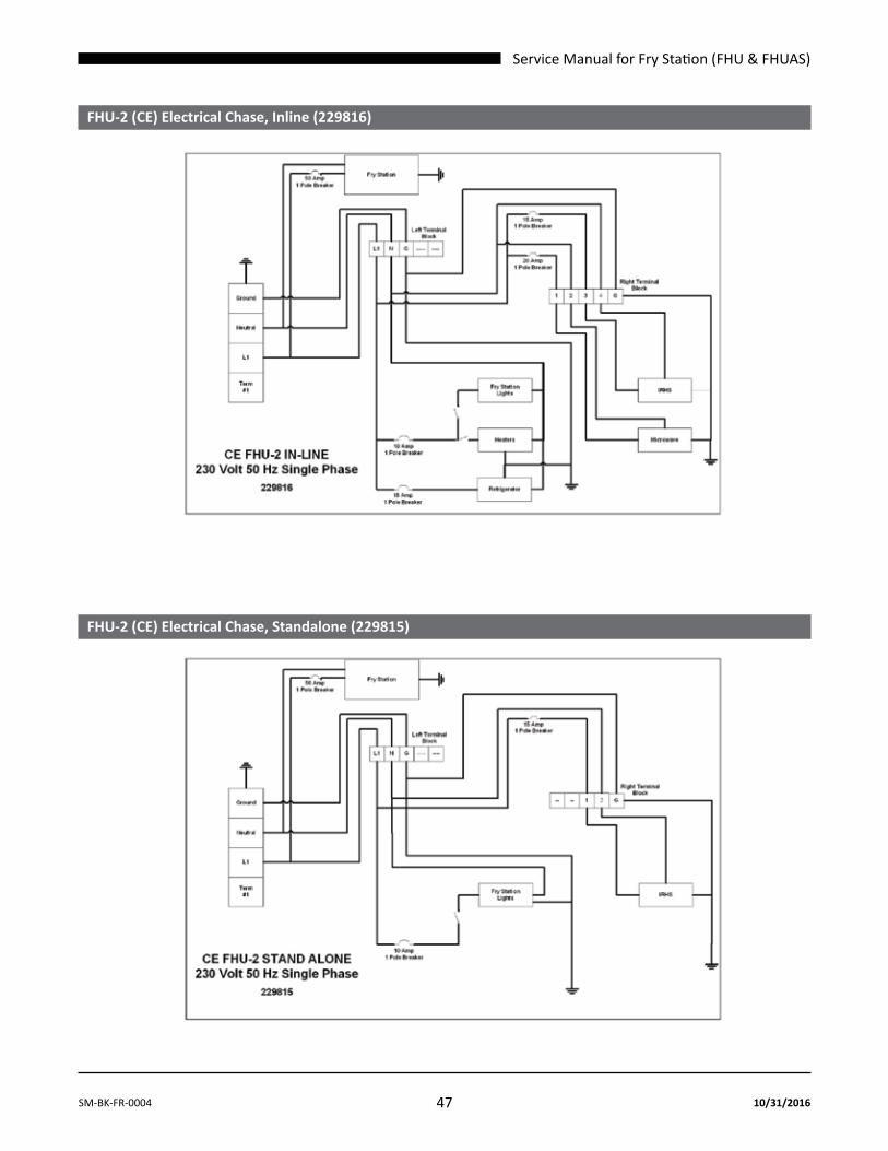
Service Manual for Fry Station (FHU & FHUAS)
47SM-BK-FR-0004 10/31/2016
Fhu-2 (CE) Electrical Chase, Inline (229816)
Fhu-2 (CE) Electrical Chase, Standalone (229815)

Service Manual for Fry Station (FHU & FHUAS)
48 SM-BK-FR-000410/31/2016
FHU-2 (japan) electrical chase, Standalone (229835)
Fhu-1 Electrical Chase, Inline (229939)
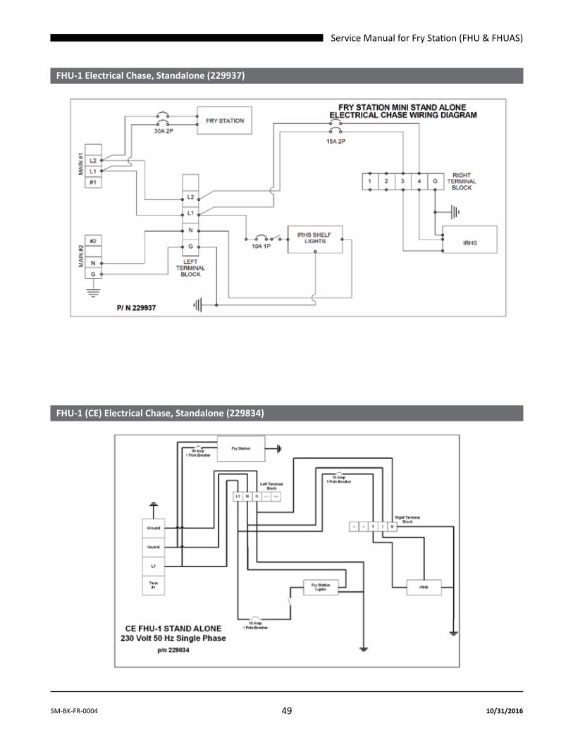
Service Manual for Fry Station (FHU & FHUAS)
49SM-BK-FR-0004 10/31/2016
Fhu-1 Electrical Chase, Standalone (229937)
Fhu-1 (CE) Electrical Chase, Standalone (229834)

Service Manual for Fry Station (FHU & FHUAS)
50 SM-BK-FR-000410/31/2016
FHU-1 (japan) electrical chase, Standalone (229813)
Fhu-1 (China) Electrical Chase, Inline (229944)

Service Manual for Fry Station (FHU & FHUAS)
51SM-BK-FR-0004 10/31/2016
FhuAS (229014)

Service Manual for Fry Station (FHU & FHUAS)
52 SM-BK-FR-000410/31/2016
FhuAS Electrical Chase, Inline (229981)
FhuAS Electrical Chase, Standalone (229949)

Service Manual for Fry Station (FHU & FHUAS)
53SM-BK-FR-0004 10/31/2016
NOTES

Service Manual for Fry Station (FHU & FHUAS)
54 SM-BK-FR-000410/31/2016