fruits of innovation - abb group · 2018-05-10 · 4 abb review 4/2008 abb review 4/2008 fruits of...
TRANSCRIPT
4 / 2008
The corporate technical journal of the ABB Group
www.abb.com/abbreview
ABBReview
Pioneering spirits
A revolution in high dc current measurement
page 6
Team-mates: MultiMove functionality heralds a new era in robot applications
page 26
Best innovations 2004page 43
a
Fruits of innovation
Innovation highlights of 2008page 6
Record breaker: switchgear for ultra-high-voltagepage 20
FlexPickerTM IRB 360: the pick-and-pack robotpage 29

The light bulb is a symbol, if not the archetype of innovation. Artificial light has given mankind unprec-edented flexibility in the scheduling of activities, and hence permitted huge breakthroughs ranging from personal freedom to industrial pro-ductivity. Electric light is possibly even the most visible man-made artifact when the Earth is viewed from Space.
Not all innovations must change the world in such a profound manner, but they do advance the cutting edge of technology in their own specific areas. This issue of ABB Review, Fruits of innovation, celebrates the brightest of the break throughs of 2008.

3ABB Review 4/2008
Editorial
Global society is rallying together to try to mitigate a number of major challenges currently facing mankind. The most prominent of these challenges are the rapid decline of fresh water resources, shortages of primary energy reserves and the negative consequences of global warming.
The media highlights these challenges, arguing that a dramatic change in people’s attitude is required and new technology breakthroughs must be made immediately to solve the problems. A revolutionary change in technology, however, is not always necessary. Frequently, the most effective solutions are made by adapting existing technolo-gies so that they evolve to solve new problems. Since these technologies already exist, they are rarely recognized by the media as groundbreaking, yet they can be very effec-tive. Innovations in industry have been evolving quietly, receiving very little media attention, yet the technology to help mitigate the challenges we face today are to a large extent already available. By taking existing technology and applying it to solve new problems, huge time-consuming leaps in technology development are not required. Small innovative steps frequently lead to the rapid development of solutions without attracting media attention.
Take, for example, the huge potential for energy savings that could be made in buildings, private houses, office suites and factories. By taking existing technologies and applying them to new problems and making small innova-tive breakthroughs, ABB has developed a user-friendly control system, called “Living Space,” to manage the energy used to operate a building efficiently.
ABB can now connect huge wind farms far out to sea to onshore grids through subsea DC cables at high voltage, and can connect hydropower plants to grids across inter-
national boundries, such as from Norway to the Nether-lands. These innovations have made it possible to exploit remote renewable energy resources that would otherwise have been out of reach.
Feeding the energy-hungry mega-cities of China’s east coast with power generated thousands of kilometers away in the west has required a step up to ultra-high voltages above 1 MV. This step was required to significantly reduce the transmission losses that would be incurred using conventional approaches. New challenges in switchgear technology, well proven in millions of lower-voltage level installations, was made to cope with these new ultra-high voltage levels. ABB is proud to have made this evolution-ary step and demonstrate the world’s first 1,100 kV gas-insulated switchgear in China.
The capabilities of robots are also evolving: The ABB Flex-Picker, the robot that was already able to sort small pieces in a production line at high speed, can now, in its second generation, perform 130 operations per minute, moving loads in the kilogram range to new locations with a preci-sion of less than a millimeter at acceleration speeds of more than 10 G.
These are only a few examples of the silent evolutionary changes that ABB has promoted. ABB will continue to im-prove technologies and develop new applications, providing a foundation for solutions to the challenges that lie ahead.
In this issue of ABB Review, we want to share with you some of our evolving technologies. The fruits of our annual investment of more than $1 billion in research and devel-opment are harvested by our customers, adding up to a rich table of improvements for society at large.
Enjoy your reading.
Peter TerwieschChief Technology OfficerABB Ltd.
A silent evolution

4 ABB Review 4/2008
ABB Review 4/2008Fruits of innovation
Contents
Innovation highlights
6An innovative 2008ABB Review highlights eight great innovations
of the year.
Product innovations
11Living SpaceSavings at your fingertips: Busch-Jaeger’s stylish Living
Space® concept makes saving energy more attractive
than ever.
15Getting it right the first timeThe RE_60_ family of relays is ready to take the baton in
distribution applications.
20Breaking newsABB is breaking records with its ultra-high-voltage
gas-insulated switchgear in China.
25Smarter platform, smarter processABB rolls out an improved quality control system for the
paper industry.
29Picking a winner and packing a punchThe second-generation FlexPickerTM is grabbing more
than headlines.
System innovations
34Taming the electric gridNetworking means power: Improved wide-area
monitoring is helping control grid stability.
40The future is nowA link buried beneath the sea bed: The world’s largest
offshore wind farm is going live with HVDC transmission.
44Integrated safetySafety shouldn’t be an afterthought. With System 800xA
High Integrity, it is an integral part of the control system.
R&D focus
49Fueling efficiencyFood for thought: ABB’s System 800xA is successfully
monitoring small bioethanol production plants.
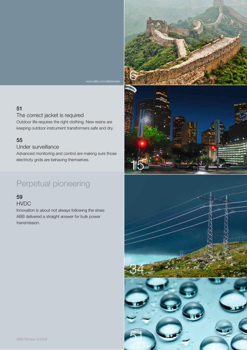
ABB Review 4/2008
6
15
34
51
51The correct jacket is requiredOutdoor life requires the right clothing: New resins are
keeping outdoor instrument transformers safe and dry.
55Under surveillanceAdvanced monitoring and control are making sure those
electricity grids are behaving themselves.
Perpetual pioneering
59HVDCInnovation is about not always following the sines:
ABB delivered a straight answer for bulk power
transmission.
www.abb.com/abbreview

6 ABB Review 4/2008
An innovative 20082008
In ABB labs and research centers across the world, more than 6,000 scientists and engineers are hard at work developing the technologies that will make the products of tomorrow possible.
Numerous successes are scored every year, and selecting the “greatest innovations” from among these is no easy task. The technologies presented here are but a small sample of the achievements worthy of note. They have been selected to give an insight into the various areas in which ABB’s research and development teams are active.
The features presented on these pages provide a brief overview of these innovations. They are discussed in more detail in full-length articles elsewhere in this edition of ABB Review.
7ABB Review 4/2008
An innovative 2008
Themenbereich
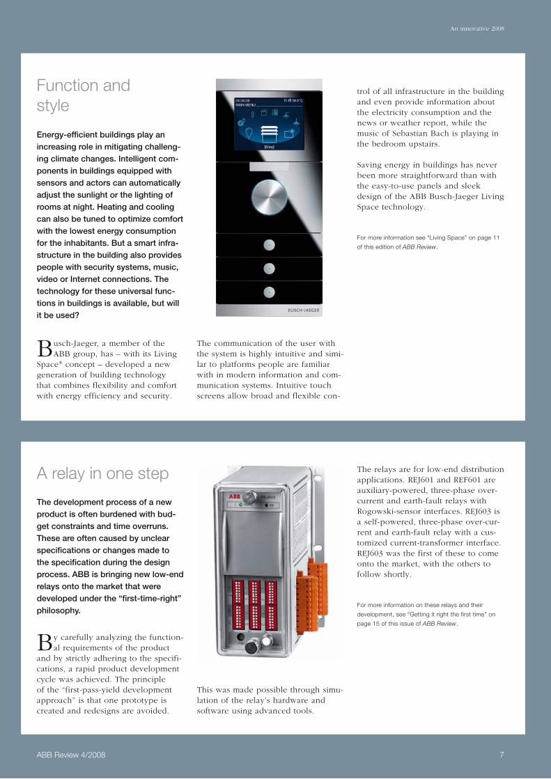
Function and style
Energy-efficient buildings play an increasing role in mitigating challeng-ing climate changes. Intelligent com-ponents in buildings equipped with sensors and actors can automatically adjust the sunlight or the lighting of rooms at night. Heating and cooling can also be tuned to optimize comfort with the lowest energy consumption for the inhabitants. But a smart infra-structure in the building also provides people with security systems, music, video or Internet connections. The technology for these universal func-tions in buildings is available, but will it be used?
Busch-Jaeger, a member of the ABB group, has – with its Living
Space® concept – developed a new generation of building technology that combines flexibility and comfort with energy efficiency and security.
The communication of the user with the system is highly intuitive and simi-lar to platforms people are familiar with in modern information and com-munication systems. Intuitive touch screens allow broad and flexible con-
trol of all infrastructure in the building and even provide information about the electricity consumption and the news or weather report, while the music of Sebastian Bach is playing in the bedroom upstairs.
Saving energy in buildings has never been more straightforward than with the easy-to-use panels and sleek design of the ABB Busch-Jaeger Living Space technology.
For more information see “Living Space” on page 11
of this edition of ABB Review.
A relay in one step
The development process of a new product is often burdened with bud-get constraints and time overruns. These are often caused by unclear specifications or changes made to the specification during the design process. ABB is bringing new low-end relays onto the market that were developed under the “first-time-right” philosophy.
By carefully analyzing the function-al requirements of the product
and by strictly adhering to the specifi-cations, a rapid product development cycle was achieved. The principle of the “first-pass-yield development approach” is that one prototype is created and redesigns are avoided.
This was made possible through simu-lation of the relay’s hardware and software using advanced tools.
The relays are for low-end distribution applications. REJ601 and REF601 are auxiliary-powered, three-phase over-current and earth-fault relays with Rogowski-sensor interfaces. REJ603 is a self-powered, three-phase over-cur-rent and earth-fault relay with a cus-tomized current-transformer interface. REJ603 was the first of these to come onto the market, with the others to follow shortly.
For more information on these relays and their
development, see “Getting it right the first time” on
page 15 of this issue of ABB Review.
Thema
Themenbereich
An innovative 2008
Themenbereich
8 ABB Review 4/2008
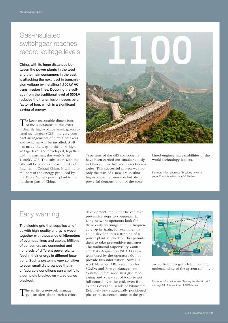
Early warning
The electric grid that supplies all of us with high-quality energy is woven together with thousands of kilometers of overhead lines and cables. Millions of consumers are connected and hundreds of different power plants feed in their energy in different loca-tions. Such a system is very sensitive to even small disturbances that in unfavorable conditions can amplify to a complete breakdown – a so-called blackout.
The earlier a network manager gets an alert about such a critical
development, the better he can take preventive steps to counteract it. Long-network operators look for these early warnings about a frequen-cy drop in Spain, for example, that could develop into a tripping of a power plant in Sweden. This permits them to take preventitive measures. The traditional Supervisory Control and Data Acquisition (SCADA) sys-tems used by the operators do not provide this information. Now Net-work Manager, ABB’s solution for SCADA and Energy Management Systems, offers wide-area grid moni-toring and a new set of tools to get full control over the grid, even if it extends over thousands of kilometers. Relatively few strategically positioned phasor measurement units in the grid
are sufficient to get a full, real-time understanding of the system stability.
For more information, see “Taming the electric grid”
on page 34 of this edition of ABB Review.
Gas-insulated switchgear reaches record voltage levels
China, with its huge distances be-tween the power plants in the west and the main consumers in the east, is attacking the next level in transmis-sion voltage by installing 1,100 kV AC transmission lines. Doubling the volt-age from the traditional level of 550 kV reduces the transmission losses by a factor of four, which is a significant saving of energy.
To keep reasonable dimensions of the substations at this extra-
ordinarily high-voltage level, gas-insu-lated switchgear (GIS), the very com-pact arrangements of circuit breakers and switches will be installed. ABB has made the leap to this ultra-high-voltage level and developed, together with its partners, the world’s first 1,100 kV GIS. The substation with this GIS will be installed near the city of Jingmen in Central China. It will trans-mit part of the energy produced by the Three Gorges power plant to the northern part of China.
Type tests of the GIS components have been carried out simultaneously in Chinese, Swedish and Swiss labora-tories. This successful project was not only the start of a new era in ultra-high-voltage transmission but also a powerful demonstration of the com-
bined engineering capabilities of the world technology leaders.
For more information see “Breaking news” on
page 20 of this edition of ABB Review.

9ABB Review 4/2008
An innovative 2008
Themenbereich
A new quality control system for papermakers
ABB’s new Network Platform, the key component of its quality control system (QCS) for papermakers, is helping to reduce costs and maintain ABB’s place as the number-one pro-vider of QCSs in the paper industry worldwide.
The modern production of paper involves an almost unimaginable
array of technology, of which the scanning platform is the focal point. The sensors in the platform measure conditions such as the moisture or fiber orientation of the paper as it is manufactured. The sensor data is then collated and fed into sophisticated control algorithms, which generate instructions for the paper machine.
Network Platform features state-of-the-art technology, is fully compliant with modern standards and has the capacity to accommodate many new technology advances.
New diagnostics tools and displays help increase customers’ access to the
paper process data. This, coupled with the overall simplicity and flexi-bility of the system, reduces training requirements and eases the configura-tion in the factory and during project delivery.
Building, installing and testing object code when the source is modified can now be done in just two to four hours. In addition, the de facto stan-dard application language C++ is used in the scanning platform for maximum portability and supportability.
For more on ABB’s Network Platform, see “Smarter
platform, smarter process” on page 25 of this issue of
ABB Review.
Stormy weather
With globally increasing requests for renewable energy, power generation with turbines are constantly on the increase. Meanwhile, wind farms with a total rating of more than 15,000 MW are being planned for the North and Baltic Seas, with the first of them already in the implementation phase. Germany, a pioneer in wind energy, is building the world’s largest wind farm far out in the North Sea. On comple-tion of the wind-farm projects current-ly underway in this area, the North Sea wind-farm network will have a rating of approximately 6,300 MW.
Now ABB is going to supply the first connections to the North Sea wind-farm network, featuring an HVDC Light system rated at 400 MW. 128 km of submarine cable and 75 km of under ground cable will transport energy from this first connection node for several wind farms to the trans-mission grid at the transformer sub-station on the German coast.
For more information, see “The future is now” on
page 40 of this edition of ABB Review.
To transport the electrical power over more than 100 km requires
HVDC transmission systems with cable connections. ABB had recently demonstrated how the appropriate HVDC Light® technology could pro-vide such a service, when it complet-ed the Estlink between Finland and Estonia in less than 20 months – a world record for the installation of such a system.

An innovative 2008
Themenbereich
10 ABB Review 4/2008
The new generation FlexPickerTM
The newly developed second-genera-tion FlexPickerTM will ensure that ABB remains at the forefront of robotic solutions, meeting the rapidly growing demands made by the picking and packing industry to improve produc-tivity.
The new FlexPicker IRB 360 takes advantage of the highly successful
design features of the IRB 340, allow-ing heavier payloads, reduced floor space usage, easier maintenance and improved operation flexibility. The basic delta robot design remains. It consists of three arms, each a parallel-ogram, connected by universal joints to the tool interface. The heavy motor components remain in the base box, so that the lightweight arms can move rapidly with reproducible accuracy.
A smaller version was developed to increase productivity within restricted factory floor space. Improvements in the QuickMoveTM and TrueMoveTM motion controller produce faster cycle times so that productivity can be maintained with fewer robots, again saving space. This improved motion controller, fitted to all FlexPicker IRB 360 generation robots, allows in-creased payloads due to its superior movement control and also reduces collision damage by detecting mal-functions and automatically stopping operations.
The high demands of the food indus-try led to the development of a ver-sion that is easily cleaned using hot, high-pressure water at close range. Further universal improvements in component durability ensure that the new generation FlexPicker is more robust and requires less maintenance.
For more information, see “Picking a winner and
packing a punch” on page 29 of this edition of
ABB Review.
Putting the safety into the control system
No matter whether we are at home or at work, a disregard for safety is an open door for accidents. In process plants, safety monitoring relies on sophisticated systems supporting humans in their vigilance. Whereas
traditionally these were typically add-ons, operating independently of the control system, the growing complex-ity of plants is making this option in-creasingly inflexible and costly. ABB’s response is the 800xA High Integrity safety system, which can be fully inte-grated into the company’s System 800xA control-system platform.
Because the 800xA High Integrity safety system is an integral part
of the System 800xA control platform, it has access to all necessary process data and is able to supply all safety-relevant information to the operator. Supported by a common sequence of event and alarm-handling functions, operators are able to analyze hazard-ous events as they unfold and make key decisions that can potentially prevent or significantly mitigate the consequences thereof.
With largely similar equipment and software tools in place for process-control and safety systems, the overall
operator training required is reduced, understanding is increased and com-plexities are removed.
In 2008, ABB’s 800xA High Integrity platform was awarded an SIL31) safety certificate.
For more information on the 800xA High Integrity
platform, see “Integrated safety” on page 44 of this
issue of ABB Review.
Footnote1) Safety integrity level (SIL) is a measure of the
r elative level of risk reduction, with SIL3 being the
highest level typically found in the process industry.

11ABB Review 4/2008
Product innovations
We live in a society where online access to all kinds of information has become the norm. Mobile phones, for example, combine a broad range of functions, ranging from “simply” making phone calls through taking photographs, recording videos and playing music in a very high quality to surfing the Internet and writing e-mails. A similarly universal platform has now become available for the first time in an area of huge practical importance: the control of buildings. With the Busch-Jaeger’s Living Space® concept, ABB has developed a new generation of building-system technol-ogy that allows a high level of flexibility, combining comfort with energy efficiency and security. Living Space not only fulfill, the need for comprehensive information, it also enables the much needed optimization of the energy consumption in buildings.
Living SpaceA new dimension of building controlBernhard Dörstel

12 ABB Review 4/2008
Living Space
Product innovations
Jaeger will play a pioneering role in the broad introduction of more energy efficiency and security in all kinds of buildings.
In this offering, it is the supposedly small details that make the difference. An example is the consistent color coding of particular functions such as illumination, blinds, heating or light scenes. All illumination functions are identified by the color yellow (sym-bolizing the sun and brightness), heat-ing functions are marked amber (for warmth and comfort), and the blind control is labeled in blue (symbolizing coolness and the color of the sky). Magenta, symbolizing extravagance, theatre and staging, is used for light scenes 1 . These codes are language-independent and can be internationally understood.
The user-control concept forms the basis of the new Busch-Jaeger product range and offers various solutions for modern building control, from a dis-tributed-control unit to a central multi-media panel.
The stylish presentation of hidden intelligence within a building under-lines a positive attitude towards life.
A single control unit for all rooms The new distributed room control unit, Busch-priOn, bridges the gap between the company’s classical switch program and modern panel solutions. It provides clear and intui-tive control of building-system tech-nology components such as illumina-tion, heating/air conditioning or blinds. A central aspect of its com-fortable use is the color-oriented control concept. And thanks to its modular structure, Busch-priOn can be individually adapted to the users’ needs 2 .
The variety of available functions opens up much room for individual freedom. Light, blinds, and consumer electronics can be controlled individu-ally or integrated into complete “living scenes”. This allows the desired back-
Another prerequisite for a widespread adoption of this technology is a so-phisticated design. As the intuitive user interface forms the only visible part of the underlying technology, it is particularly important for the user’s acceptance that the feeling of doing something sensible for the environ-ment is enhanced by elegance and style.
The use of comprehensive control schemes covering the illumination as well as the climate control of a building enables an energy saving potential of almost 60 percent.
For most people, the stylish presenta-tion of hidden intelligence within a building underlines a positive attitude towards life and should not be under-estimated as “door opener” for inno-vative technology.
ABB has recognized this need and taken its building technology products and systems onto a new level in terms of user friendliness and elegance. The innovative solutions Bush-priON and Bush-ComfortTouch from Busch-
Modern building-system technology plays a key role when it comes
to reducing the energy consumption of buildings. According to current studies, the use of comprehensive control schemes covering the illumi-nation as well as the climate control of a building enables an energy saving potential of almost 60 percent.
Although this potential has been iden-tified and the implementation of cor-responding measures is urgently need-ed, universal control systems are far from ubiquitous. Why? Even in highly industrialized countries, many people are afraid of using allegedly “compli-cated” technology. Negative experi-ences imprinted by exposure to non-ergonomic video recorders, television sets or even PCs, which typically de-manded the extensive study of a thick manual to permit use of even the most basic functions, linger on with many users. The consumer industry has rec-ognized this inhibition threshold and is striving to develop “fool-proof” controls for complicated devices.
To be more attractive for the user, energy-saving building-system tech-nology must therefore adequately present the options to the user, or integrate them into an intuitive user interface.
1 Example of a light scene atmosphere which can be switched on at the touch of a button

13ABB Review 4/2008
Living Space
Product innovations
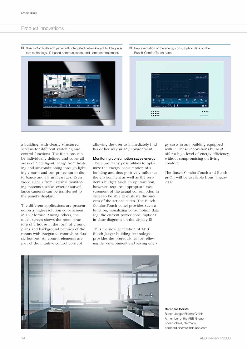
the first time, makes the Busch-Com-fortTouch panel an intelligent supple-ment to the private Internet PC, which it can even partially replace 4 . The Busch-ComfortTouch panel not only provides the occupants with a central control element for the entire building system technology, it also represents an intuitively controllable communica-tion center. Checking the current weather report or the stock ticker on the Internet, receiving e-mails, playing music, watching video clips – all this is possible with the Busch-Comfort-Touch panel.
The rotary control element represents a very distinc-tive and even style-form-ing design feature which will be familiar to many users from other applica-tions.
It goes without saying that the new Busch-ComfortTouch panel offers all possibilities that permit a comfortable control of the technical equipment in
Extra comfort and energy efficiency is provided by an optional infrared receiver and proximity sensor on the upper border strip of the Bush-priON. This combines design and function in an intelligent way: When an occupant comes close, it automatically activates the background illumination of the room control unit. Similarly, the lower cover strip can be combined with a temperature sensor and a room-tem-perature controller.
A window to the worldWith the new Busch-ComfortTouch, Busch-Jaeger extends its range of control panels by an exceptionally innovative variant. With its design and choice of material based on the award-winning Busch control panels, the Busch-ComfortTouch offers con-siderably more functions and a larger display, virtually dissolving the boundaries between building-system technology, home entertainment and IP-based communication.
All control elements of the system, including the TFT display, feature a switch-selectable day and night illumination allowing the level of brightness to be adapted accordingly.
The possibility to display and control IP- and LAN- or WLAN-based applica-tions from the fields of home enter-tainment and IP-based communica-tion, which has been implemented for
drop to be created at the touch of a button: The light is dimmed, blinds are closed, and the favorite music is played.
During the development of Bush-priOn, simplicity and ease of use were accord-ed top priority. The system is con-trolled via touch-sensitive or rotary control elements. The central module consists of a thin-film transistor (TFT) graphic display combined with a rotary control element. The fine-tuned rotary knob with colored backlighting and the clearly structured display allow intuitive and safe control of all functions 3 .
Each function can be selected and controlled quickly and comfortably. Individual lamps can be controlled and dimmed directly. Shutters and blinds can also be controlled with the rotary control element, and the climate in the building can be set for each room individually using the single-room temperature control function.
The rotary control element represents a very distinctive and even style-form-ing design feature which will be familiar to many users from other applications (eg, in cars) or from the iPod.
The rotary control element can be combined or extended with different modules. All control elements of the system, including the TFT display, feature a switch-selectable day and night illumination allowing the level of brightness to be adapted accord-ingly.
2 Single a and triple b control element with intuitive color coding and symbolsa b
3 Busch-priOn three gang combination in “glass black”
14 ABB Review 4/2008
Living Space
Product innovations
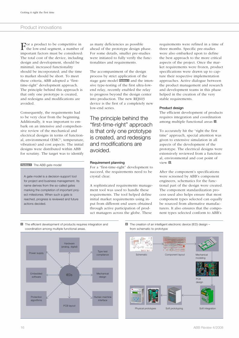
gy costs in any building equipped with it. These innovations by ABB offer a high level of energy efficiency without compromising on living comfort.
The Busch-ComfortTouch and Busch-priOn will be available from January 2009.
Bernhard Dörstel
Busch-Jaeger Elektro GmbH
A member of the ABB Group
Lüdenscheid, Germany
allowing the user to immediately find his or her way in any environment.
Monitoring consumption saves energy There are many possibilities to opti-mize the energy consumption of a building and thus positively influence the environment as well as the resi-dent’s budget. Such an optimization, however, requires appropriate mea-surement of the actual consumption in order to be able to evaluate the suc-cess of the actions taken. The Busch-ComfortTouch panel provides such a function, visualizing consumption data (eg, the current power consumption) in clear diagrams on the display 5 .
Thus the new generation of ABB Busch-Jaeger building technology provides the prerequisites for reliev-ing the environment and saving ener-
a building, with clearly structured screens for different switching and control functions. The functions can be individually defined and cover all areas of “intelligent living” from heat-ing and air-conditioning through light-ing control and sun protection to dis-turbance and alarm messages. Even video signals from external monitor-ing systems such as exterior surveil-lance cameras can be transferred to the panel’s display.
The different applications are present-ed on a high-resolution color screen in 16:9 format. Among others, the touch screen shows the room struc-ture of a house in the form of ground plans and background pictures of the rooms with integrated controls or clas-sic buttons. All control elements are part of the intuitive control concept
4 Busch-ComfortTouch panel with integrated networking of building sys-tem technology, IP-based communication, and home entertainment.
5 Representation of the energy consumption data on the Busch-ComfortTouch panel

As the demand for low-end intelligent electronic devices (IEDs) grows, ABB is responding by developing its own portfolio of low-end relays. In this context, the company initiated its RE_60_ program in late 2005. The immediate focus of this program was to address the development of the REJ601, REF601 and REJ603 relay types.
Getting it right the first timeInnovative development of low-end intelligent relays for distribution applicationsBernhard Deck, Vijay Shah, Kornel Scherrer, Gerhard Salge
15ABB Review 4/2008
Product innovations
REJ601 and REF601 are auxiliary-powered, three-phase over-current and earth-fault relays with Rogowski-sensor interfaces. REJ603 is a self-powered, three-phase over-current and earth-fault relay with customized CT interface. REJ603 was the first of these products to come onto the market. The launch of REF601 will follow shortly.
16 ABB Review 4/2008
Getting it right the first time
Product innovations
requirements were refined in a time of three months. Specific pre-studies were also embarked upon to define the best approach to the more critical aspects of the project. Once the mar-ket requirements were frozen, product specifications were drawn up to cap-ture their respective implementation approaches. Active dialogue between the product management and research and development teams in this phase helped in the creation of the very stable requirements.
Product designThe efficient development of products requires integration and coordination among multiple functional areas 1 .
To accurately hit the “right the first time” approach, special attention was given to extensive simulation in all aspects of the development of the prototype. The electrical designs were extensively reviewed from a function-al, environmental and cost point of view 2 .
After the component’s specifications were screened by ABB’s component engineers, schematics for the func-tional part of the design were created. The component standardization pro-cess used also helps ensure that most component types selected can equally be sourced from alternative manufac-turers. It also ensures that the compo-nent types selected conform to ABB’s
as many deficiencies as possible ahead of the prototype design phase. For some details, smaller pre-studies were initiated to fully verify the func-tionalities and requirements.
The accompaniment of the design process by strict application of the stage gate model Factbox 1 and the inten-sive type-testing of the first ultra-low-end relay, recently enabled the relay to progress beyond the design center into production. The new REJ603 device is the first of a completely new low-end series.
The principle behind the “first-time-right” approach is that only one prototype is created, and redesigns and modifications are avoided.
Requirement planningFor a “first-time-right” development to succeed, the requirements need to be crystal clear.
A sophisticated requirements manage-ment tool was used to handle these requirements. The tool helped define initial market requirements using in-put from different end users obtained through active participation of prod-uct managers across the globe. These
For a product to be competitive in the low-end segment, a number of
important factors must be considered: The total cost of the device, including design and development, should be minimal; increased functionality should be incorporated; and the time to market should be short. To meet these criteria, ABB adopted a “first-time-right” development approach. The principle behind this approach is that only one prototype is created, and redesigns and modifications are avoided.
Consequently, the requirements had to be very clear from the beginning. Additionally, it was important to em-bark on an intensive and comprehen-sive review of the mechanical and electrical designs in terms of function-al, environmental (EMC1), temperature, vibration) and cost aspects. The initial designs were distributed within ABB for scrutiny. The target was to identify
1 The efficient development of products requires integration and coordination among multiple functional areas.
Human machineinterface
Mechanicaldesign
Type testcompliance
Hardware(analog, digital)
Power supply
Embeddedsoftware
Protectionalgorithms
PCB layout
IEDs
Factbox 1 The ABB gate model
A gate model is a decision-support tool
for project and business management. Its
name derives from the so-called gates
marking the completion of important proj-
ect milestones. When such a gate is
reached, progress is reviewed and future
actions decided.
2 The creation of an intelligent electronic device (IED) design – from schematic to prototype
Schematic
Physical prototypes
Component layout
Soft prototyping
Mechanical modeling
Soft integration
PCBdesign

17ABB Review 4/2008
Getting it right the first time
Product innovations
modeling of the complete product helped optimize the internal product layout with efficient use of available volume. It also helped eliminate phys-ical issues related with inter-PCBA or PCBA-mechanics mismatches. This approach minimized iterative aspects and related conflicts that must typical-ly be dealt with in a traditional devel-opment cycle.
Following this soft modeling of the products, design for assembly (DFA) and design for manufacturing (DFM) analyses were performed on the inte-grated soft prototypes. This way, the critical aspects of the review were covered, while shorter cycles were achieved in the manufacturing line.
An automated test system enabling reduced product test cycles on the shop floor during production was also designed. This system helps to per-form the high quality functional check for each sample and ensures a com-mon product-test platform for the IEDs of ABB’s Distribution Automa-tion Product Group.
The profiling of the code in a simulated environ-ment facilitated in the estimation of the real-time performance of critical modules, reducing the post-integration effort.
REJ603 technical highlightsREJ603 is a self-powered three-phase non-directional overcurrent and earth-fault protection device with DMT4) and IDMT5) characteristics.
The relay offers two-stage, short-cir-cuit and time-over-current protection against phase-to-phase and earth-faults, being immune to magnetizing transformer inrush. It has extensive
broader requirements. This facilitates economies of scale for components used in common with other products of ABB’s Distribution Automation divi-sion.
Special attention was giv-en to extensive simulation in all aspects of the devel-opment of the prototype.
The selection of the digital core (mi-crocontroller) took into account the flexibility required of the architecture so that it could meet the product’s short- and long-term development requirements (with scalable features and reusability of code).
The schematics were subsequently translated for PCB2) layouts with the standard footprint/PCB decal libraries. The process followed common guide-lines for PCBA3) specifications so as to ensure reduction in the cycle time in PCBA manufacturing. PCB layouts were also reviewed for optimal immu-nity to electromagnetic interference.
Embedded code that was to become an integral part of the product was also handled in a high-level language (HLL) environment. The code is struc-tured so as to support maximum reus-ability of modules. The profiling of the code in a simulated environment also facilitated in the estimation of the real-time performance of critical mod-ules, reducing the post-integration effort.
Specialized hardware test code was also developed for the boards to be able to test basic hardware readiness immediately on the receipt of the PCBA.
The mechanical side was designed in parallel. This process also captured the 3-D models of the PCBA. Soft
3 Self-powered feeder protection relay REJ603 for secondary distribution protection
Factbox 2 Additional highlights of the REJ603 relay
Dual mode of earth-fault measurement:
internal calculation and external CBCT*)
input
Integrated IDMT curves (IEC and spe-
cial) in a single product to cover time
coordination needs of secondary distri-
bution protection
Capacitor discharge impulse output for
low-energy trip coil
Built-in manual-reset electromechanical
flag for trip indication
Easy setting by DIP switches, protected
by a transparent cover
Compact design and mounting arrange-
ment suitable for ring main unit (RMU)
applications
Test facility for testing entire scheme,
including primary CT, relay, and trip coil
External binary input, activated by an
external voltage input, which can be
utilized for remote tripping of the circuit
breaker
Footnote*) CBCT: core balance current transformer
Footnotes1) EMC: electro-magnetic compatibility2) PCB: printed circuit board.3) PCBA: PCB assembly4) DMT: definite minimum time (a DMT relay is designed so that the time needed for the relay to release is
approximately constant over the working current range of the relay)5) IDMT: inverse definite minimum time (an IDMT relay is designed so that the time needed for the relay to release
is inverse to the current over part of its working range)

18 ABB Review 4/2008
Getting it right the first time
Product innovations
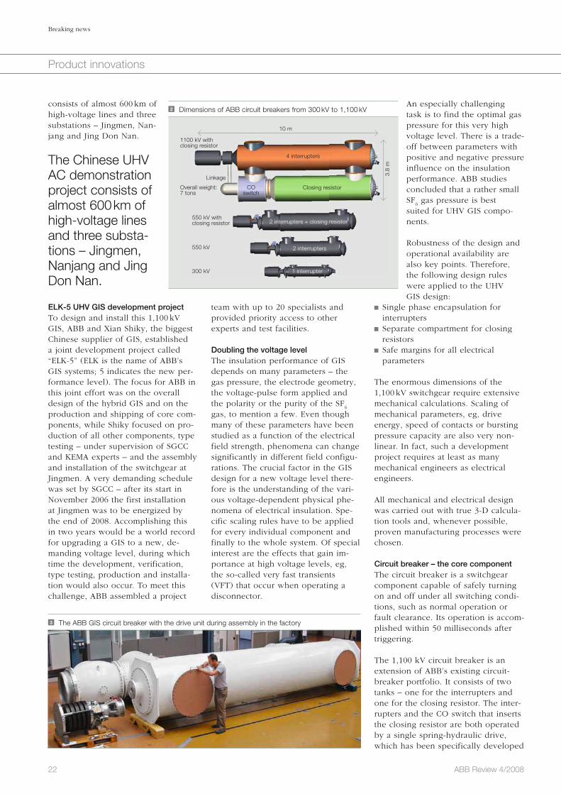
availability, compactness and safety of medium-voltage switchgears.The RE_ 601 relay has a user-friendly design. The pre-adapted inputs/out-puts and universal power supply allow the relay to suit to user needs easily. In addition, the LCD display and five dedicated LEDs clearly display online measurement data and faults, events / fault records allowing them to be rap-idly analyzed and dealt with.
Optional communication allows the relay to connect to control and moni-toring systems through serial commu-nication for remote control and moni-toring.
Some of the additional features of the RE_ 601 4 are listed in Factbox 3 .
Area of applicationRE_ 601 is a numerical feeder protec-tion relay, designed for the protection and control of utility and industrial
fault protection with DMT and IDMT characteristics. It uses Rogowsky cur-rent sensors for phase-current mea-surement.
With its compact size and unique technical features, the RE_ 601 series is an ideal solution for retrofits and implementations in restricted spaces.
The relay offers three-stage, short-cir-cuit and time overcurrent protection against phase-to-phase faults and two-stage protection against earth-faults, and is immune to magnetizing trans-former inrush. It has extensive self-super vision capabilities. The integrated protection of the RE_ 601 devices, along with the benefits of modern cur-rent sensors, provide the improved
self-diagnosis capabilities and a fail-safe feature that causes the circuit breaker to trip when the phase cur-rent exceeds 20 times the Is
max current
of interface CT and there is a critical failure of the internal relay.
Some of the additional highlights of the REJ603 3 are shown in Factbox 2 .
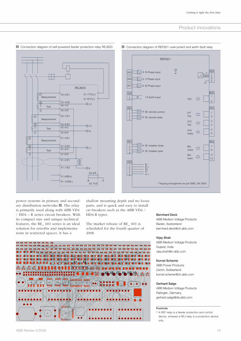
Area of application REJ603 is designed for the selective short-circuit and earth-fault protection of feeders in secondary distribution networks and for protection of trans-formers in utilities and industries. The device is a self-powered numerical relay, requiring no external supply voltage, making it an ideal choice for installation even in remote locations where auxiliary supplies are not avail-able. The relay is primarily used in ring-main units within distribution networks and it derives power from the primary current transformers 5 .
The REJ603 has been commercially released.
REJ601 / REF601The REJ601 / REF6016) is an auxiliary-powered relay providing three-phase non-directional overcurrent and earth-
Factbox 3 Additional highlights of the RE_ 601 relay
Integrated IDMT curves (IEC and spe-
cial) in a single product
Sensor interface eliminates need for
current transformers with different nomi-
nal values
Availability of four selectable current
ranges
Unit-ready/internal-relay failure, protec-
tion start and trip indications via LEDs
Phase overcurrent and earth-fault indi-
cation through separate LEDs
Universal-range power supply providing
compatibility to different conditions of
the installation’s supply-voltage
External input for remote trip and
remote reset
Local as well as remote breaker control
(only on REF601)
Optional remote serial communication
feature over MODBUS-RTU protocol
Test facility for relay hardware
4 ABB’s REF601 a and REJ601 b relaysa b
19ABB Review 4/2008
Getting it right the first time
Product innovations
Bernhard Deck
ABB Medium Voltage Products
Baden, Switzerland
Vijay Shah
ABB Medium Voltage Products
Gujarat, India
Kornel Scherrer
ABB Power Products
Zürich, Switzerland
Gerhard Salge
ABB Medium Voltage Products
Ratingen, Germany
Footnote6) A REF relay is a feeder protection and control
device, whereas a REJ relay is a protection device
only.
shallow mounting depth and no loose parts, and is quick and easy to install on breakers such as the ABB VD4 / HD4-R types.
The market release of RE_ 601 is scheduled for the fourth quarter of 2008.
power systems in primary and second-ary distribution networks 6 . The relay is primarily used along with ABB VD4 / HD4 – R series circuit breakers. With its compact size and unique technical features, the RE_ 601 series is an ideal solution for retrofits and implementa-tions in restricted spaces. It has a
6 Connection diagram of REF601 overcurrent and earth-fault relay
REF601
R-Phase inputUaux
+
-
XK5
XK6
XK7
XK8
XK9
XK2
XK2
XK10
XK4
XK1
XK3
12
1234
1
2
3
4
5
6
7
8
9
10
1
2
1234
1234
12345
Y-Phase input
B-Phase input
BI: remote control
BI: breaker close
BI: remote reset
BI: breaker open
B -B +IGA -A +
1A Earth inputTrip*
E/FTrip
O/CTrip
Unitready
Bkr.close
Bkr.open
* Tripping arrangement as per ENEL DK 5600
�
5 Connection diagram of self-powered feeder protection relay REJ603
REJ603
Measurement
Measurement
Measurement
Test
S1
S1
S1
S2
S2
S2
C
C
C
D
D
D
X2-3/S1 X1-7/TC(+)
X1-8/TC(-)X2-4/S2
L3
L2
N
L1
E
X2-1/C
X2-2/D
X2-7/S1
X2-8/S2X2-5/C
X2-6/D
X1-4/S1
X1-3/S2X1-5/C
X1-6/D
X1-2/S1
X1-1/S2
X2-9/E
X2-10/E
X1-9/BI(+)
X1-10/BI(-)
Test
Test

China is in urgent need of electrical power. Huge power plants are built all over the country and the enormous flow of electrical power to the large megacities has to cross several thousand kilometers from the source to the end user.
At those dimensions, losses of the power lines can be significant. The State Grid Corporation of China (SGCC) is thus aiming for 1,100 kV as the voltage level for AC transmission to keep losses as low as possible, a step into a new area of electrical grids.
ABB, together with its partners and suppliers, has developed the heart of such a system – a gas-insulated switchgear design – that could pass all the tests with this groundbreaking technology.
Breaking newsUltra-high-voltage switchgear to power ChinaWalter Holaus, Fredi Stucki
20 ABB Review 4/2008
Product innovations

21ABB Review 4/2008
Breaking news
Product innovations
finally determine the technical feasi-bility, a group of three Chinese and two Japanese GIS manufacturers and ABB were asked by SGCC to take part in the development of UHV GIS equipment for the Chinese UHV AC demonstration project. It was estab-lished in 2008 in central China and
The State Grid Corporation of China (SGCC) – one of ABB’s biggest cus-tomers – began designing an AC sys-tem with a rated voltage of 1,100 kV a few years ago [3]. This project initi-ated extensive research and develop-ment efforts in research institutes and at equipment manufacturers [4]. To
Reliable supply of electrical energy is one of the backbones of mod-
ern economies. Its safe and reliable operation mainly depends on high-voltage switchgear – the core part of an electrical power system. The high-voltage circuit breaker in this switch-gear is often the last line of defense when big systems must be protected in the event of a short circuit.
Electrical grids and the corresponding substations are well known as air-insulated systems in which the high voltage is kept away from both the ground and people by distances of tens of meters.
Another much more compact way of building high-voltage switchgear is the gas-insulated design – gas-insu-lated switchgear (GIS) Factbox 1 .
GIS technology was intro-duced to the market in 1966 with the first 170 kV GIS underground substa-tion delivered to the Zürich city center.
GIS technology was introduced to the market in 1966 with the first 170 kV GIS underground substation delivered to the Zürich city center 1 . In 1976, ABB delivered the first 500 kV GIS to Claireville, Canada. With the installa-tion of the first 800 kV GIS in South Africa in 1986, ABB has proven its technology leadership also at the ul-tra-high-voltage (UHV) level Factbox 2 . This so-called alpha substation has been in operation for more than 20 years without any failures or un-planned interruptions. The 500 kV GIS in Itaipu, Brazil is still the world’s largest installation but will soon be overtaken by the ABB GIS inside the Three Gorges Dam in China.
China and innovative GIS technologyChina is a huge country where electric power generation happens mainly in the western parts and load centers are typically found in the coastal region – thousands of kilometers apart. Both AC and DC UHV systems are neces-sary to handle the increase in electric energy consumption and to back up the existing transmission system [1,2].
Factbox 1 Gas-insulated switchgear (GIS)
Gas-insulated switchgear is widely used in
high-voltage transmission and distribution
systems. ABB is the leading supplier of GIS
at transmission voltage levels. ABB GIS
products range from 72 kV up to 800 kV rat-
ed voltage with rated currents up to 4,000 A
and a short-circuit current switching capabili-
ty up to 63,000 A. GIS is used in indoor and
outdoor applications. The functions provided
by GIS are switching, disconnecting, earth-
ing and measuring. As a system with many
components, each GIS is optimized for the
required application. GIS components have
a coaxial design with an inner and outer
conductor, filled with sulfur hexafluoride (SF6)
gas at several hundred kPA overpressure.
They are connected to each other by bolted
flanges – this is why GIS looks like pipelines
from outside. Substation designs are called
“hybrid GIS” if parts of it (eg, busbars or
connections to overhead lines) are air insu-
lated.
Factbox 2 Ultra-high voltage (UHV)
Electric power systems are operated at dif-
ferent voltage levels to optimize transmission
efficiency, minimize electrical losses and ma-
terial consumption, and maintain maximum
operational safety. The IEC standards pro-
vide standardized voltage levels up to
800 kV. Systems operated at a rated voltage
above 550 kV are called “ultra-high-voltage”
systems. They are used when several thou-
sand MW of electric energy have to be trans-
mitted over hundreds of kilometers. As
transmission losses are comparably lower at
higher voltages, a step from 550 kV to
1,100 kV reduces the losses by a factor of
four. Therefore, UHV systems are especially
suitable to efficiently transport bulk power
over large distances.
1 ABB’s GIS history: from first research projects to the world’s largest installation within 50 years
First 170 kV GISSemperteig (CH)
First 500 kV GISClaireville (CA)
Largest 500 kV GISItaipu (BR)
First 800 kV GISAlpha (ZA)
500 kV GISThree Gorges (CN)
First 500 kV GIS inChina, Jiangmen
First 1100 kV GISJingmen (CN)
First research
© A
BB
Pow
er T
echn
olog
y P
rodu
cts,
BU
PP
HV
-1
1956 1966 1976 1986 1996
> 170 kV
< 170 kV
2006 2010
22 ABB Review 4/2008
Breaking news
Product innovations
An especially challenging task is to find the optimal gas pressure for this very high voltage level. There is a trade-off between parameters with positive and negative pressure influence on the insulation performance. ABB studies concluded that a rather small SF
6 gas pressure is best
suited for UHV GIS compo-nents.
Robustness of the design and operational availability are also key points. Therefore, the following design rules were applied to the UHV GIS design:
Single phase encapsulation for interrupters
Separate compartment for closing resistors
Safe margins for all electrical parameters
The enormous dimensions of the 1,100 kV switchgear require extensive mechanical calculations. Scaling of mechanical parameters, eg, drive energy, speed of contacts or bursting pressure capacity are also very non-linear. In fact, such a development project requires at least as many mechanical engineers as electrical engineers.
All mechanical and electrical design was carried out with true 3-D calcula-tion tools and, whenever possible, proven manufacturing processes were chosen.
Circuit breaker – the core component The circuit breaker is a switchgear component capable of safely turning on and off under all switching condi-tions, such as normal operation or fault clearance. Its operation is accom-plished within 50 milliseconds after triggering. The 1,100 kV circuit breaker is an extension of ABB’s existing circuit-breaker portfolio. It consists of two tanks – one for the interrupters and one for the closing resistor. The inter-rupters and the CO switch that inserts the closing resistor are both operated by a single spring-hydraulic drive, which has been specifically developed
team with up to 20 specialists and provided priority access to other experts and test facilities.
Doubling the voltage levelThe insulation performance of GIS depends on many parameters – the gas pressure, the electrode geometry, the voltage-pulse form applied and the polarity or the purity of the SF
6
gas, to mention a few. Even though many of these parameters have been studied as a function of the electrical field strength, phenomena can change significantly in different field configu-rations. The crucial factor in the GIS design for a new voltage level there-fore is the understanding of the vari-ous voltage-dependent physical phe-nomena of electrical insulation. Spe-cific scaling rules have to be applied for every individual component and finally to the whole system. Of special interest are the effects that gain im-portance at high voltage levels, eg, the so-called very fast transients (VFT) that occur when operating a disconnector.
consists of almost 600 km of high-voltage lines and three substations – Jingmen, Nan-jang and Jing Don Nan.
The Chinese UHV AC demonstration project consists of almost 600 km of high-voltage lines and three substa-tions – Jingmen, Nanjang and Jing Don Nan.
ELK-5 UHV GIS development projectTo design and install this 1,100 kV GIS, ABB and Xian Shiky, the biggest Chinese supplier of GIS, established a joint development project called “ELK-5” (ELK is the name of ABB’s GIS systems; 5 indicates the new per-formance level). The focus for ABB in this joint effort was on the overall design of the hybrid GIS and on the production and shipping of core com-ponents, while Shiky focused on pro-duction of all other components, type testing – under supervision of SGCC and KEMA experts – and the assembly and installation of the switchgear at Jingmen. A very demanding schedule was set by SGCC – after its start in November 2006 the first installation at Jingmen was to be energized by the end of 2008. Accomplishing this in two years would be a world record for upgrading a GIS to a new, de-manding voltage level, during which time the development, verification, type testing, production and installa-tion would also occur. To meet this challenge, ABB assembled a project
2 Dimensions of ABB circuit breakers from 300 kV to 1,100 kV
1100 kV with closing resistor
Overall weight:7 tons
550 kV withclosing resistor
550 kV
300 kV
Linkage
4 interrupters
CO switch
Closing resistor
2 interrupters + closing resistor
2 interrupters
1 interrupter
10 m
3.8
m
3 The ABB GIS circuit breaker with the drive unit during assembly in the factory

23ABB Review 4/2008
Breaking news
Product innovations
nector is designed in a 90-degree setup with a visible gap of the inner conductor of less than 300 mm. This gap can withstand more than 3,400 kV
Extensive space requirements for the laboratory: The combined volt-age tests needed two bushings at a distance of more than 13 m, with each of them a distance of more than 10 m to the laboratory walls.
The power-switching tests were mostly performed on one-half of the circuit breaker only, as no suffi-ciently high voltage was available to stress the full-size breaker. This so-called half-pole testing requires a specific enclosure and voltage grad-ing calculations.
As a result of the careful design and manufacturing, the circuit breaker could be successfully tested during the first test series.
The UHV GIS disconnectorThe basic function of a disconnector is to disconnect parts of the GIS to safely do maintenance work on the disconnected and earthed parts.
The focus for ABB in this joint effort was on the overall design of the hybrid GIS and on the production and shipping of core components. Compared with a circuit breaker, it may operate rather slowly within a few seconds. ABB’s 1,100 kV discon-
by ABB for this application [5, 6, 7]. A comparison of ABB’s circuit break-ers for different voltage levels is given in 2 . The rated values of 1,100 kV, 4,000 A correspond to a rated power of 7,600 MW for the three phases. This is more than the average electric pow-er consumption of Switzerland.1) With this rating the circuit breaker would be capable of turning on and off the electrical power of Switzerland.
The total weight of this modern UHV circuit breaker is only 7.5 tons due to the optimized number of interrupters and the aluminum enclosures 3 .
Since it was the world’s first equip-ment rated at 1,100 kV, it had to be tested according to international and Chinese standards; the equipment suppliers and especially the test labo-ratories thus faced big challenges. Type testing for the circuit breaker was accomplished at Xihari test labo-ratories in Xian and at ABB in Switzer-land 4 .
Huge efforts were required to perform the power tests in Xihari at the 1,100 kV level. The most demanding topics were: Manufacturing and testing required the intercontinental transport of UHV equipment. Airfreight of com-plete circuit breakers and other equipment was required to meet the tight schedule of the project.
Factbox Ratings specified for the 1,100 kV GIS demonstration project
Rated voltage 1,100 kV
Rated lightning
impulse voltage 2,400 kV
Rated equipment current 4,000 A
Rated busbar current 8,000 A
Rated short-circuit curren 50 kA
4 Development team and test pole for the 1,100 kV circuit breaker at Baden Power Lab (Switzerland ) after T100s test
5 Cross-section of the UHV disconnector
a Driveb Moving contactc Fixed contactd Insulatore Insulator
a bc
d
e
a Bushingb Bushingc High-voltage AC test transformerd High-voltage DC test transformere Circuit breakerf UHV GIS busbarg Disconnector under test
better qualitypicture without text
6 Arrangement for disconnector switching tests at the STRI laboratory
a
c
e
f g
d
b
24 ABB Review 4/2008
Breaking news
Product innovations
ries. This project was not only the start of a new era in ultra-high-voltage transmis-sion but also a powerful demonstration of the com-bined engineering capabili-ties of the world’s technology leaders.
Walter Holaus
Fredi Stucki
ABB Switzerland Ltd.
Zürich, Switzerland
The on-site workload is small and allows for fast installation.
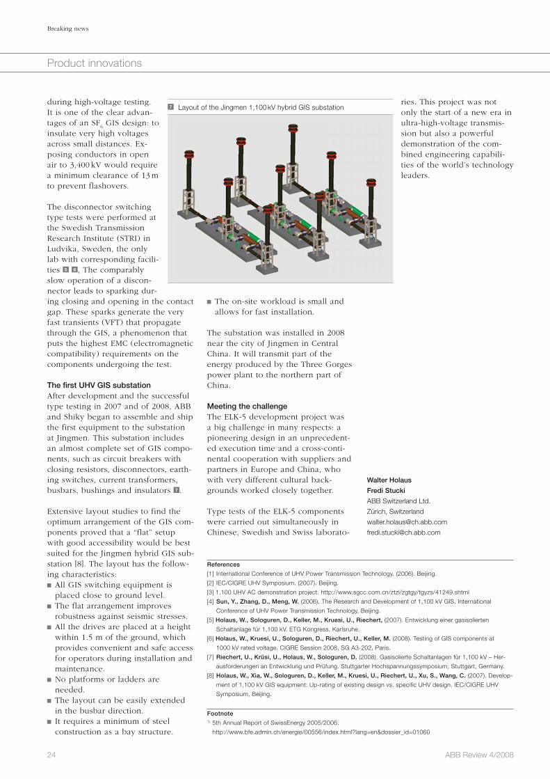
The substation was installed in 2008 near the city of Jingmen in Central China. It will transmit part of the energy produced by the Three Gorges power plant to the northern part of China.
Meeting the challengeThe ELK-5 development project was a big challenge in many respects: a pioneering design in an unprecedent-ed execution time and a cross-conti-nental cooperation with suppliers and partners in Europe and China, who with very different cultural back-grounds worked closely together.
Type tests of the ELK-5 components were carried out simultaneously in Chinese, Swedish and Swiss laborato-
during high-voltage testing. It is one of the clear advan-tages of an SF
6 GIS design: to
insulate very high voltages across small distances. Ex-posing conductors in open air to 3,400 kV would require a minimum clearance of 13 m to prevent flashovers.
The disconnector switching type tests were performed at the Swedish Transmission Research Institute (STRI) in Ludvika, Sweden, the only lab with corresponding facili-ties 5 6 , The comparably slow operation of a discon-nector leads to sparking dur-ing closing and opening in the contact gap. These sparks generate the very fast transients (VFT) that propagate through the GIS, a phenomenon that puts the highest EMC (electromagnetic compatibility) requirements on the components undergoing the test.
The first UHV GIS substationAfter development and the successful type testing in 2007 and of 2008, ABB and Shiky began to assemble and ship the first equipment to the substation at Jingmen. This substation includes an almost complete set of GIS compo-nents, such as circuit breakers with closing resistors, disconnectors, earth-ing switches, current transformers, busbars, bushings and insulators 7 .
Extensive layout studies to find the optimum arrangement of the GIS com-ponents proved that a “flat” setup with good accessibility would be best suited for the Jingmen hybrid GIS sub-station [8]. The layout has the follow-ing characteristics: All GIS switching equipment is placed close to ground level.
The flat arrangement improves robustness against seismic stresses.
All the drives are placed at a height within 1.5 m of the ground, which provides convenient and safe access for operators during installation and maintenance.
No platforms or ladders are needed.
The layout can be easily extended in the busbar direction.
It requires a minimum of steel construction as a bay structure.
7 Layout of the Jingmen 1,100 kV hybrid GIS substation
References
[1] International Conference of UHV Power Transmission Technology. (2006). Beijing.
[2] IEC/CIGRE UHV Symposium. (2007). Beijing.
[3] 1,100 UHV AC demonstration project. http://www.sgcc.com.cn/ztzl/zgtgy/tgyzs/41249.shtml
[4] Sun, Y., Zhang, D., Meng, W. (2006). The Research and Development of 1,100 kV GIS. International
Conference of UHV Power Transmission Technology, Beijing.
[5] Holaus, W., Sologuren, D., Keller, M., Kruesi, U., Riechert, (2007). Entwicklung einer gasisolierten
Schaltanlage für 1,100 kV. ETG Kongress, Karlsruhe.
[6] Holaus, W., Kruesi, U., Sologuren, D., Riechert, U., Keller, M. (2008). Testing of GIS components at
1000 kV rated voltage. CIGRE Session 2008, SG A3-202, Paris.
[7] Riechert, U., Krüsi, U., Holaus, W., Sologuren, D. (2008). Gasisolierte Schaltanlagen für 1,100 kV – Her-
ausforderungen an Entwicklung und Prüfung. Stuttgarter Hochspannungssymposium, Stuttgart, Germany.
[8] Holaus, W., Xia, W., Sologuren, D., Keller, M., Kruesi, U., Riechert, U., Xu, S., Wang, C. (2007). Develop-
ment of 1,100 kV GIS equipment: Up-rating of existing design vs. specific UHV design. IEC/CIGRE UHV
Symposium, Beijing.
Footnote1) 5th Annual Report of SwissEnergy 2005/2006.
http://www.bfe.admin.ch/energie/00556/index.html?lang=en&dossier_id=01060

25ABB Review 4/2008
Product innovations
For some 20 years, ABB’s Smart Platform has been the workhorse of its quality control system (QCS) for papermakers and has helped maintain ABB’s place as the number-one QCS provider in the paper industry world-wide. ABB has renewed this technology platform by introducing the Network Platform. This new product represents a significant advance on many fronts and provides a base upon which further exciting features can be built.
Smarter platform, smarter processNetwork Platform: a new quality control system for the paper industry Robert Byrne, Anthony Byatt
26 ABB Review 4/2008
Smarter platform, smarter process
Product innovations
the air in the sensor gap is very care-fully temperature controlled.
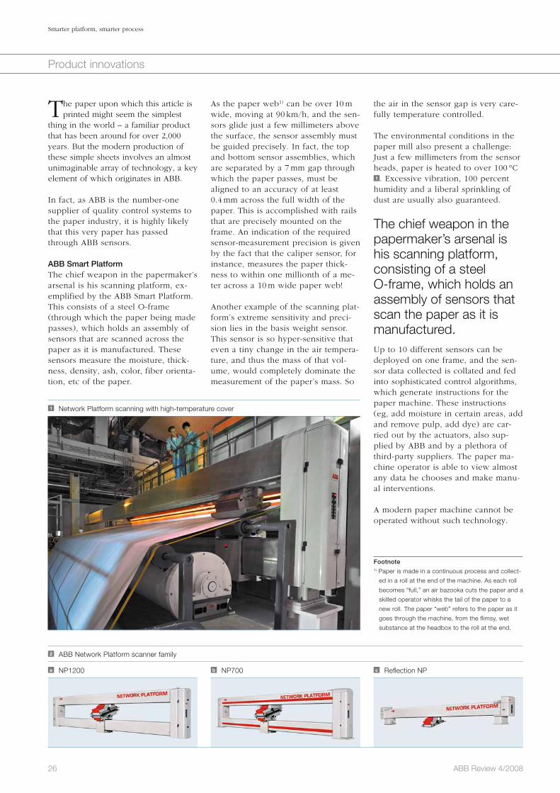
The environmental conditions in the paper mill also present a challenge: Just a few millimeters from the sensor heads, paper is heated to over 100 °C 1 . Excessive vibration, 100 percent humidity and a liberal sprinkling of dust are usually also guaranteed.
The chief weapon in the papermaker’s arsenal is his scanning platform, consisting of a steel O-frame, which holds an assembly of sensors that scan the paper as it is manufactured.Up to 10 different sensors can be deployed on one frame, and the sen-sor data collected is collated and fed into sophisticated control algorithms, which generate instructions for the paper machine. These instructions (eg, add moisture in certain areas, add and remove pulp, add dye) are car-ried out by the actuators, also sup-plied by ABB and by a plethora of third-party suppliers. The paper ma-chine operator is able to view almost any data he chooses and make manu-al interventions.
A modern paper machine cannot be operated without such technology.
As the paper web1) can be over 10 m wide, moving at 90 km/h, and the sen-sors glide just a few millimeters above the surface, the sensor assembly must be guided precisely. In fact, the top and bottom sensor assemblies, which are separated by a 7 mm gap through which the paper passes, must be aligned to an accuracy of at least 0.4 mm across the full width of the paper. This is accomplished with rails that are precisely mounted on the frame. An indication of the required sensor-measurement precision is given by the fact that the caliper sensor, for instance, measures the paper thick-ness to within one millionth of a me-ter across a 10 m wide paper web!
Another example of the scanning plat-form’s extreme sensitivity and preci-sion lies in the basis weight sensor. This sensor is so hyper-sensitive that even a tiny change in the air tempera-ture, and thus the mass of that vol-ume, would completely dominate the measurement of the paper’s mass. So
The paper upon which this article is printed might seem the simplest
thing in the world – a familiar product that has been around for over 2,000 years. But the modern production of these simple sheets involves an almost unimaginable array of technology, a key element of which originates in ABB.
In fact, as ABB is the number-one supplier of quality control systems to the paper industry, it is highly likely that this very paper has passed through ABB sensors.
ABB Smart PlatformThe chief weapon in the papermaker’s arsenal is his scanning platform, ex-emplified by the ABB Smart Platform. This consists of a steel O-frame (through which the paper being made passes), which holds an assembly of sensors that are scanned across the paper as it is manufactured. These sensors measure the moisture, thick-ness, density, ash, color, fiber orienta-tion, etc of the paper.
1 Network Platform scanning with high-temperature cover
2 ABB Network Platform scanner family
a NP1200 b NP700 c Reflection NP
Footnote1) Paper is made in a continuous process and collect-
ed in a roll at the end of the machine. As each roll
becomes “full,” an air bazooka cuts the paper and a
skilled operator whisks the tail of the paper to a
new roll. The paper “web” refers to the paper as it
goes through the machine, from the flimsy, wet
substance at the headbox to the roll at the end.
27ABB Review 4/2008
Smarter platform, smarter process
Product innovations
tral design paradigm Factbox 2 . This tool allows developers to create complex state machines by using simple mod-eling constructs. These constructs can then be extended by the developers with customized code that applies to any given problem domain. In the case of Network Platform, this domain is the measurement of paper proper-ties.
In addition to Rational Rose, other IBM products were utilized by the Network Platform development team to ensure a seamless tool integration, from software inception to application
At any paper mill in the world, there is a good chance that ABB’s Smart Platform is scanning the paper as it rolls – literally – off the machine. Several thousand of these systems have been installed in the field.
ABB continually strives to enhance its products and bring the latest tech-nologies to its customers, thereby enabling cost reduction, greater reli-ability and increased performance.
Factbox 1 Network Platform advantages
Improved visibility and diagnostics
Modern platform to enable continued
product development for the next 10 to
15 years
Improved ease of use for the customer
and service engineers (tools, software
updates, reduced training)
Facilitates addition of new sensors and
sensor complements
Easier factory configuration and project
delivery
Faster scanning at 600 mm/s
(1,000 mm/s is planned)
Improved integration with System 800xA
Asset Optimization and remote diagnos-
tics
Increased capability to accommodate
new technologies
Better use of RAM and CPU real-time
capabilities, at 25 percent and less than
5 percent, respectively
Rapid integration of new sensor devel-
opments
Factbox 2 Benefits of using UML
Distributed development
– Using configuration management
tools, each software component can
be managed independently of the
complete solution.
– Black boxes with defined inputs and
outputs can be used early in the de-
velopment life cycle for undeveloped
components.
Portability of solution
– The same code base can be used to
deliver a solution on multiple operat-
ing-system platforms.
Self-documenting code
– The tight coupling of code with the
design model ensures that design
documents always reflect the current
code state.
4 Network Platform configuration utility3 Network Platform diagnostics tool
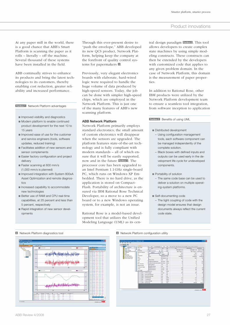
Through this ever-present desire to “push the envelope,” ABB developed its new QCS product, Network Plat-form, helping keep the company at the forefront of quality control sys-tems for papermakers 2 .
Previously, very elegant electronics boards with elaborate, hard-wired logic were required to handle the huge volume of data produced by high-speed sensors. Today, the job can be done with simpler high-speed chips, which are employed in the Network Platform. This is just one of the many features of ABB’s new scanning platform.
ABB Network PlatformNetwork Platform primarily employs standard electronics; the small amount of custom electronics will disappear when the sensors are upgraded. The platform features state-of-the-art tech-nology and is fully compliant with modern standards – all of which en-sure that it will be easily supported, now and in the future Factbox 1 . The processor core has been upgraded to an Intel Pentium 1.1 GHz single-board PC, which runs on Windows XP Em-bedded. There is no hard drive, as the application is stored on Compact-Flash. Portability of architecture is en-sured via IBM Rational Rose Technical Developer, so a move to a new PC board or to a new Windows operating system, for example, is not an issue.
Rational Rose is a model-based devel-opment tool that utilizes the Unified Modeling Language (UML) as its cen-

28 ABB Review 4/2008
Smarter platform, smarter process
Product innovations
in Columbus, Ohio (United Sates), Bangalore (India) and Dundalk (Ire-land), pooling many man years of effort to complete the project. Huge emphasis was placed on the test man-agement, and the zero-defect rate in the first product shipments has proven the value of the stringent test strategy.
Future perfectThis new modern platform will enable continued QCS product development for the next 10 to 15 years and will accommodate many new technology advances, such as flexible scan pat-terns, wireless technology, ultra-fast scanning and the integration of very high-speed sensors. With only 25 per-cent of the RAM capability and about 2 to 5 percent of the CPU real-time capability currently being used, there is enough reserve horsepower to drive many new ideas!
Already, advanced testing is taking place on two new core sensors that both have a performance specification far in advance of any comparable sensor from the competition. Only the Network Platform could provide the processing muscle to deal with the very high-speed raw data and the very advanced diagnostics offered by these new sensors.
The first production systems have already been shipped and are per-forming very well indeed. Deliveries are ramping up and dozens of ABB Network Platforms will be running in paper mills all over the world within the year.
Robert Byrne
Anthony Byatt
ABB Pulp and Paper QCS CoE
Dundalk, Ireland
dramatically increased the customers’ access to the paper process data 3 . This, coupled with the overall simplic-ity and flexibility of the system, reduc-es training requirements and eases the configuration in the factory and dur-ing project delivery 4 . For example, sensor-complement assignment, in which the system is set up for its par-ticular permutation of sensors (almost every system is different), was previ-ously a complex task but is now very simple, as is integration with System 800xA Asset Optimization and remote diagnostics features.
Substantially improved diagnostic tools and displays have dramatically increased the customers’ access to the paper process data.
ABB’s Network Platform also provides a lower cost of ownership for the cus-tomer through: Improved ease of use for the install-er and maintainer of the system
Support for remote connectivity Enhanced support for sensor additions in the field
Better support for software upgrades in the field
Improved support for external safety I/O
The development project itself was an excellent example of successful inter-national cooperation with teams based
deployment. These include Rational RequisitePro for requirements capture, Rational Test RealTime for black-box testing, and Rational TestManager for the control and recording of system tests. The use of these integrated tools ensured that the difficulties normally associated with pan-continental devel-opment teams (in this case from Europe, Asia and North America), such as disparate times zone, cultural differences and physical distance between team members, could be managed with the minimum amount of effort.
The new software brings a host of new features Factbox 3 . It now takes a mere two to four hours to build, in-stall and test object code when the source is modified. A single DVD contains all the manuals and docu-mentation. And the de facto standard application language C++ has been chosen for maximum portability and supportability.
In addition, substantially improved diagnostic tools and displays have
Service Workstation
Factbox 3 Design features
Software architecture ensures operat-
ing-system-platform independence
Use of commercial off-the-shelf
electronics aided in reducing design
life cycle
Simplified cooling of end-column
electronics by use of air cooling

Picking a winner and packing a punchThe second-generation FlexPickerTM
Klas Bengtsson
29ABB Review 4/2008
Product innovations
The demand for new automation solutions in indus-try is great and nowhere more so than in the packaging industry. Traditionally, picking and packing has been labor intensive. Often, a range of assorted products are packed at high speed into boxes, trays or blisters. The high pace of the pro-cess using manual labor can result in production bottlenecks affecting throughput. Employee health problems can also develop as a result of the highly repetitive nature of the work.
Automation is an attractive alternative and picking and packing robotic solutions represents one of the fastest growing markets in the automation industry. ABB already has an installed base of over 2,500 delta robots, specifically designed for this type of ap-plication, and it is a world-leader in picking and packing technology. The newly developed second-generation FlexPickerTM will ensure that ABB remains at the forefront of this industry, helping customers to improve their productivity.

fragmented. There are more than 25,000 food plants globally and large multinational food companies like KRAFT Foods and Nestle, despite their size, hold less than 5 percent of the market share. The companies selling packaging solutions are also numer-ous and fragmented, which presents an obvious obstacle to ABB, when seeking efficient sales channels to the customer.
From the outset, ABB’s strategy was to sell products rather than complete solutions or installations. It was per-ceived that the most effective strategy would be to sell products to existing system integrators and machine build-ers who were already active in the packaging industry. The objective was to create a demand for ABB’s robot-based automation within a market that already had well-established alterna-tive solutions. The challenge was not only to sell ABB robots to system inte-grators, but also to create market awareness, so that the end customer would demand robot-based solutions. This endeavor started to yield returns in 2003, five years after the initiative was launched, and now grows annual-ly by 30 to 40 percent. Today, the FlexPicker robot is sold mainly to the food, pharmaceutical and solar-cell industries.
Second-generation FlexPickerTen years after the introduction of IRB 340, ABB has launched the IRB 360 – a second-generation high-speed picking robot 3 . The timing for this launch was good, since the market was eager for a new picking robot. The new model satisfied this demand and even provided solutions for new applications, creating new markets, which in turn have boosted sales.
An important factor influencing the timing of the launch was that the original patent, which prevented com-petitors using parallel arms in their robots, was no longer valid. The Euro-pean patent expired at the end of
The ABB FlexPickerABB launched the FlexPicker IRB 340 in 1998. The FlexPicker is a delta ro-bot1) uniquely designed for the pick-ing industry, to pick and pack small lightweight objects such as chocolates. The design principle was quite simple: All the moving parts were made of lightweight materials, such as carbon fibers, anodized aluminum and plas-tics. The heavy motor components were all placed in a rigid, non-moving base box. All the arms were linked in parallel with three degrees of freedom and joined at the delta plate. A theta axis was added through the delta plate to give the robot an additional degree of freedom. With such a con-figuration, the FlexPicker was aptly nicknamed “the spider robot” 2 . Even though the arm system is lightweight and looks fragile, it is extremely ro-bust thanks to the high mechanical strength-to-weight ratio of the con-struction material. The lightweight arms of the robot can accelerate up to 15 m/s2 and reproducibly achieve an accuracy of 0.1 mm.
ABB is the market leader in delta robots with a well established reputation for quality and reliability, satisfying the needs of the picking and packing industry.
Although the robot had a simple design and was easy to build, control-ling it was altogether more difficult. High-speed movement was achieved relatively easily with small motors. Far more challenging was moving the robot at such speeds without causing jerky movements or destroying the manipulator. ABB was well placed to overcome such a challenge, since its advanced motion controller was supe-rior to its competitors’ for standard robots and this technology was capi-talized upon during the development of the picker. The result was the high-ly successful IRB 340, which can pick and place products quicker and more gently than any other robot.
Developing a marketThe packaging industry is huge and
30 ABB Review 4/2008
Picking a winner and packing a punch
Product innovations
1 Picking line with manual labor
2 IRB 340, a parallel arm design
The packaging industry has for de-cades used manual labor for pick-
ing and packing products into boxes, trays and blisters. A typical applica-tion is packing mixed chocolate pra-lines into blisters, a repetitive task that is performed at very high speed. This type of work is tedious and generally poorly paid, which makes it increas-ingly difficult to find and retain labor 1 . Additionally, growing concerns about food safety have encouraged the industry to seek alternative ways to pick and pack food, so that human contact is minimized. For these rea-sons, the industry has shown a great deal of interest in automation.
In the late 1990s, robots were general-ly designed in a serial manner. One part of the robot was attached to an-other in a sequential fashion and each part carried the weight of its own motor. This resulted in robots with heavy arms and slow product han-dling speeds, unable to compete with laborers capable of accomplishing 60 to 100 cycles a minute.
Footnote1) A delta robot consists of three arms connected by
universal joints to the tool interface. The arms form
a parallelogram, which maintains the orientation of
the tool interface.

31ABB Review 4/2008
Picking a winner and packing a punch
Product innovations
The benefits of advanced motion con-trol were illustrated when ABB won an order made by a Swiss pretzel pro-ducing company. ABB beat the com-petition, winning the order because the ABB delta robot could pick and place the pretzels at high speed, while reducing the scrap rate from 12 per-cent to 4 percent. The ABB motion control is suitably named Quick-MoveTM and TrueMoveTM. The IRB 360 has been developed using the newly released second-generation Quick-Move and TrueMove motion control-ler, which have allowed significant cycle-time improvements. On average, the IRB 360 is 20 percent faster than the IRB 340, with the best results for payloads of between 1.5 and 3 kg.
2006 and the US patent at the end of 2007. Now anyone can build a delta robot and compete with ABB. In this highly competitive industry it seemed obvious that other companies would immediately start building delta ro-bots. ABB’s competitive advantage would now have to rely on its long experience building these robots, its well-established reputation for quality and its large market share reflected by its large sales volume. To remain mar-ket leader in this technology, ABB’s strategy was to improve upon the ad-vantages of the old FlexPicker, so that the new FlexPicker could carry higher payloads and target new branches of the packing industry. Improvements in the design and strength of compo-nents created a more durable and robust robot that required minimal maintenance to achieve maximal operating time.
Additional design features have made the new-generation delta robots more versatile; a smaller version taking up less space on the factory floor and a new version for the food industry that allows thorough cleaning using stan-dard industrial methods. Of course the simple delta robot concept is relative-ly easy to recreate and now many companies have designed their own prototypes. The question is, how good are these new competing delta robots? Could they be good enough to reduce ABB’s market share and cause the potential loss of ABB cus-tomers?
One of the most important features of the ABB delta robot is its advanced motion control, which is fundamental to the overall performance of the machine. It is easy to build a delta design robot and incorporate a high-torque motor to move it very quickly. The challenge is to make it fast and accurate, while maintaining a long lifespan. The problem is that it is not possible to compensate for poor motion control with a “stronger” mechanical design, since the weight of the robot slows its movement. High performance comes from advanced motion control. The control loop in the ABB robot controller plans the movement of the manipulator, taking account of its dynamic behavior to reduce mechanical stress.
3 FlexPicker IRB 360 launch at PackExpo, October 2007 in the USA
Inevitably, during the picking and packing process, products occasionally appear on a picking line in unexpected places. Sometimes frozen products, for example, can be frozen together and then separate during movement, or products can be repositioned during a sudden conveyor belt shutdown. Such product relocation can cause problems for a robot, resulting in unexpected collisions. With the FlexPicker, the lightweight arm system detaches dur-ing a heavy collision. The arm system is held in place by a spring unit that protects the arm from damage during a mechanical impact, even when fully accelerating. This safety feature pro-tects the robot, but customer feedback suggested that a robot that stops mov-
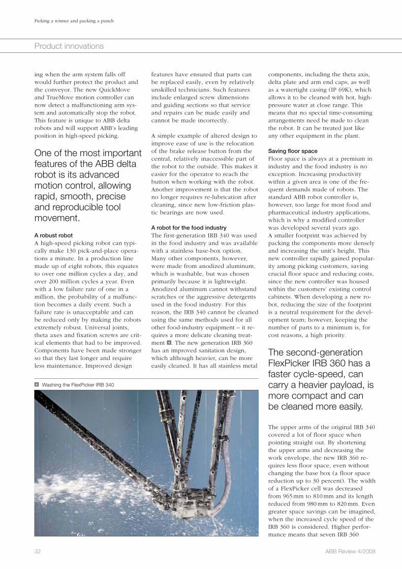
32 ABB Review 4/2008
Picking a winner and packing a punch
Product innovations
components, including the theta axis, delta plate and arm end caps, as well as a watertight casing (IP 69K), which allows it to be cleaned with hot, high-pressure water at close range. This means that no special time-consuming arrangements need be made to clean the robot. It can be treated just like any other equipment in the plant.
Saving floor spaceFloor space is always at a premium in industry and the food industry is no exception. Increasing productivity within a given area is one of the fre-quent demands made of robots. The standard ABB robot controller is, however, too large for most food and pharmaceutical industry applications, which is why a modified controller was developed several years ago. A smaller footprint was achieved by packing the components more densely and increasing the unit’s height. This new controller rapidly gained popular-ity among picking customers, saving crucial floor space and reducing costs, since the new controller was housed within the customers’ existing control cabinets. When developing a new ro-bot, reducing the size of the footprint is a neutral requirement for the devel-opment team; however, keeping the number of parts to a minimum is, for cost reasons, a high priority.
The second-generation FlexPicker IRB 360 has a faster cycle-speed, can carry a heavier payload, is more compact and can be cleaned more easily.
The upper arms of the original IRB 340 covered a lot of floor space when pointing straight out. By shortening the upper arms and decreasing the work envelope, the new IRB 360 re-quires less floor space, even without changing the base box (a floor space reduction up to 30 percent). The width of a FlexPicker cell was decreased from 965 mm to 810 mm and its length reduced from 980 mm to 820 mm. Even greater space savings can be imagined, when the increased cycle speed of the IRB 360 is considered. Higher perfor-mance means that seven IRB 360
features have ensured that parts can be replaced easily, even by relatively unskilled technicians. Such features include enlarged screw dimensions and guiding sections so that service and repairs can be made easily and cannot be made incorrectly.
A simple example of altered design to improve ease of use is the relocation of the brake release button from the central, relatively inaccessible part of the robot to the outside. This makes it easier for the operator to reach the button when working with the robot. Another improvement is that the robot no longer requires re-lubrication after cleaning, since new low-friction plas-tic bearings are now used.
A robot for the food industryThe first-generation IRB 340 was used in the food industry and was available with a stainless base-box option. Many other components, however, were made from anodized aluminum, which is washable, but was chosen primarily because it is lightweight. Anodized aluminum cannot withstand scratches or the aggressive detergents used in the food industry. For this reason, the IRB 340 cannot be cleaned using the same methods used for all other food-industry equipment – it re-quires a more delicate cleaning treat-ment 4 . The new generation IRB 360 has an improved sanitation design, which although heavier, can be more easily cleaned. It has all stainless metal
ing when the arm system falls off would further protect the product and the conveyor. The new QuickMove and TrueMove motion controller can now detect a malfunctioning arm sys-tem and automatically stop the robot. This feature is unique to ABB delta robots and will support ABB’s leading position in high-speed picking.
One of the most important features of the ABB delta robot is its advanced motion control, allowing rapid, smooth, precise and reproducible tool movement. A robust robotA high-speed picking robot can typi-cally make 130 pick-and-place opera-tions a minute. In a production line made up of eight robots, this equates to over one million cycles a day, and over 200 million cycles a year. Even with a low failure rate of one in a million, the probability of a malfunc-tion becomes a daily event. Such a failure rate is unacceptable and can be reduced only by making the robots extremely robust. Universal joints, theta axes and fixation screws are crit-ical elements that had to be improved. Components have been made stronger so that they last longer and require less maintenance. Improved design
4 Washing the FlexPicker IRB 340

33ABB Review 4/2008
Product innovations
robots can replace eight IRB 340 robots, providing total floor-space savings of as much as 40 percent.
From picking to packingThe FlexPicker IRB 340 delta robot was first developed for picking and packing small lightweight objects, which are easily relocated, using a simple vacuum cup pickup tool. Once the IRB 340 was released to the market, a large number of different product picking and packing applications were attempted. A popular application today is unloading a flow wrapper and packing products into boxes. This is typically done by grabbing eight to 12 piec-es at a time using a large multi-vacuum gripper. Of course such increased pay-loads, to some extent, slow down the FlexPicker, but worse still they can impact the inertia of the tool. The larger the offset from the center point of the robot tool, the lower the FlexPick-er’s performance. This can make the robot’s operations uneconomical, especially if the opera-tor reconfigures the system incorrect-ly. If the robot performs outside its design limits, its lifespan and mainte-nance costs may be affected.
The goal when developing the IRB 360 was to allow an increased payload by increasing the torque on the fourth (theta) axis in the middle, so that the robot would be more versatile, in-creasing its scope for new applica-tions without reducing the lifespan of the robot. Case packing with a Flex-Picker is a very common application, yet by expanding the payload from 2 to 3 kg, the number of packing applications was dramatically in-creased. The IRB 360 robot can pick up heavier products, handling sausage packs of 2 kg with a 1 kg gripper, as compared to the IRB 340 robot, which can only pick up 1.3 kg sausage packs with a 0.7 kg gripper. This im-proved performance presents the possibility of doubling production throughput.
completely phased out in October 2008. The smooth transition from IRB 340 to the IRB 360 was possible because the machines are very similar, except that the IRB 360 can outperform the IRB 340 in all aspects. Future sales are pre-dicted to grow thanks to an expanding picking market, despite the recent entry of new competitors to this mar-ket. There have already been some significant sales for the high payload variant, outper-forming standard robot solu-tions from competitors. A promising future for the stain-less FlexPicker version is also predicted in the meat indus-try. In fact, in all parts of the world, there is great interest from industries with large picking lines to install reli-able robots within a limited amount of floor space. The market is ready and there is a demand for automation with high-speed delta robots. In-stallations and requests are coming from Turkey, Latvia, Russia, India, Saudi Arabia and other nations with rapid-ly growing industries. ABB is
well positioned to meet this demand with its second-generation FlexPicker and applications experience.
Klas Bengtsson
ABB Robotics
Västerås, Sweden
5 IRB 340 case-packing coffee at Löfbergs Lila, Sweden
Earlier discussions about payload in-creases focused on redesigning the arm system. By separating the parallel arm, the new robot could be made stronger, but this would also affect its weight. A further drawback would be an increase in the number of required components, since different arm systems would be needed for different payloads. Again these problems were solved by the new motion controller. The improve-ments made in robot movement control actually made it possible to handle 3 kg payloads using the same arm system as before with even shorter cycle times. Smoother robot movement and a great-er understanding of the robot’s limita-tions have given the IRB 360 a 30 per-cent performance improvement with a 2 kg payload as compared with the IRB 340 model. Throughput can be in-creased from 30 to 50 percent in case-packing applications 5 .
The sales launchThe sale of the IRB 360 started in April 2008, and its IRB 340 predecessor was
Picking a winner and packing a punch
Taming the electric gridContinuous improvement of wide-area monitoring for enhanced grid stability Albert Leirbukt, Ernst Scholtz, Sergiu Paduraru
Several catastrophic power blackouts during the last decade have exposed a need for early warning systems in the transmission system control centers. Network ManagerTM, ABB’s solution for Supervisory Control and Data Acquisition (SCADA) and Energy Management Systems (EMS) has, since 2008, offered wide-area monitoring and a new set of tools to get full control of the grid, even when it extends over thousands of kilometers.
34 ABB Review 4/2008
System innovations
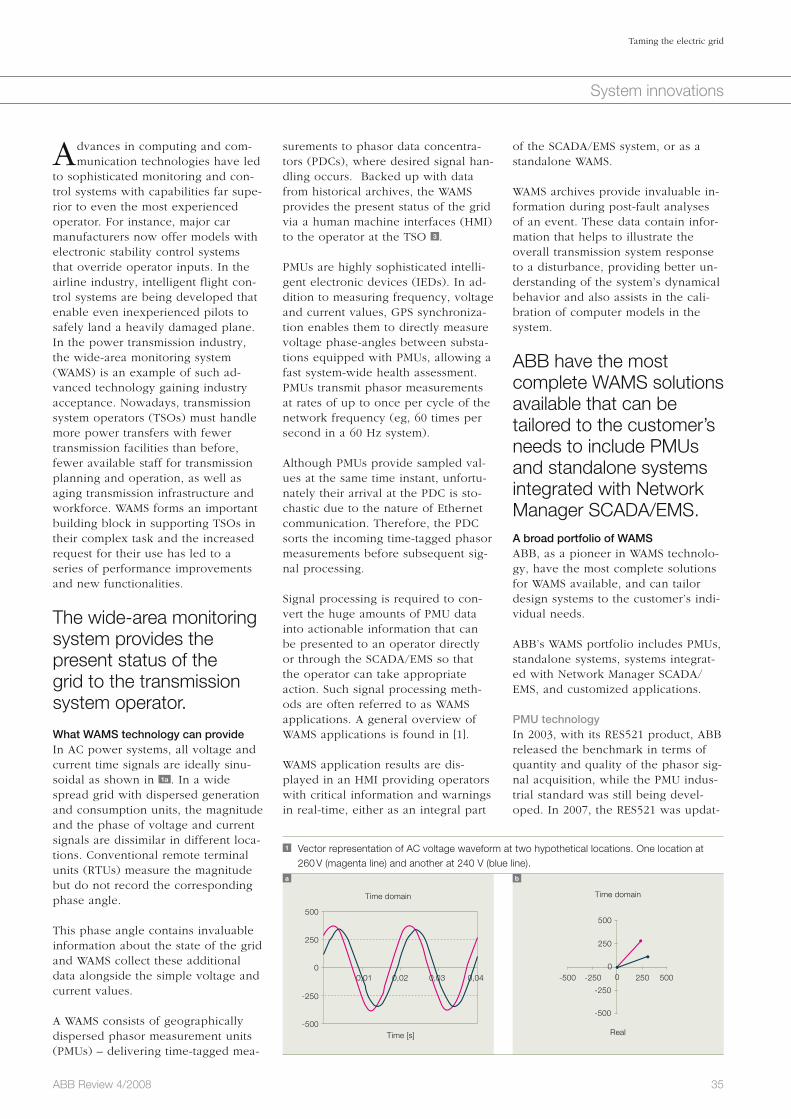
35ABB Review 4/2008
Taming the electric grid
System innovations
of the SCADA/EMS system, or as a standalone WAMS.
WAMS archives provide invaluable in-formation during post-fault analyses of an event. These data contain infor-mation that helps to illustrate the overall transmission system response to a disturbance, providing better un-derstanding of the system’s dynamical behavior and also assists in the cali-bration of computer models in the system.
ABB have the most complete WAMS solutions available that can be tailored to the customer’s needs to include PMUs and standalone systems integrated with Network Manager SCADA/EMS.A broad portfolio of WAMSABB, as a pioneer in WAMS technolo-gy, have the most complete solutions for WAMS available, and can tailor design systems to the customer’s indi-vidual needs.
ABB’s WAMS portfolio includes PMUs, standalone systems, systems integrat-ed with Network Manager SCADA/EMS, and customized applications.
PMU technologyIn 2003, with its RES521 product, ABB released the benchmark in terms of quantity and quality of the phasor sig-nal acquisition, while the PMU indus-trial standard was still being devel-oped. In 2007, the RES521 was updat-
surements to phasor data concentra-tors (PDCs), where desired signal han-dling occurs. Backed up with data from historical archives, the WAMS provides the present status of the grid via a human machine interfaces (HMI) to the operator at the TSO 3 .
PMUs are highly sophisticated intelli-gent electronic devices (IEDs). In ad-dition to measuring frequency, voltage and current values, GPS synchroniza-tion enables them to directly measure voltage phase-angles between substa-tions equipped with PMUs, allowing a fast system-wide health assessment. PMUs transmit phasor measurements at rates of up to once per cycle of the network frequency (eg, 60 times per second in a 60 Hz system).
Although PMUs provide sampled val-ues at the same time instant, unfortu-nately their arrival at the PDC is sto-chastic due to the nature of Ethernet communication. Therefore, the PDC sorts the incoming time-tagged phasor measurements before subsequent sig-nal processing.
Signal processing is required to con-vert the huge amounts of PMU data into actionable information that can be presented to an operator directly or through the SCADA/EMS so that the operator can take appropriate action. Such signal processing meth-ods are often referred to as WAMS applications. A general overview of WAMS applications is found in [1].
WAMS application results are dis-played in an HMI providing operators with critical information and warnings in real-time, either as an integral part
Advances in computing and com-munication technologies have led
to sophisticated monitoring and con-trol systems with capabilities far supe-rior to even the most experienced operator. For instance, major car manufacturers now offer models with electronic stability control systems that override operator inputs. In the airline industry, intelligent flight con-trol systems are being developed that enable even inexperienced pilots to safely land a heavily damaged plane. In the power transmission industry, the wide-area monitoring system (WAMS) is an example of such ad-vanced technology gaining industry acceptance. Nowadays, transmission system operators (TSOs) must handle more power transfers with fewer transmission facilities than before, fewer available staff for transmission planning and operation, as well as aging transmission infrastructure and workforce. WAMS forms an important building block in supporting TSOs in their complex task and the increased request for their use has led to a series of performance improvements and new functionalities.
The wide-area monitoring system provides the present status of the grid to the transmission system operator.
What WAMS technology can provide In AC power systems, all voltage and current time signals are ideally sinu-soidal as shown in 1a . In a wide spread grid with dispersed generation and consumption units, the magnitude and the phase of voltage and current signals are dissimilar in different loca-tions. Conventional remote terminal units (RTUs) measure the magnitude but do not record the corresponding phase angle.
This phase angle contains invaluable information about the state of the grid and WAMS collect these additional data alongside the simple voltage and current values.
A WAMS consists of geographically dispersed phasor measurement units (PMUs) – delivering time-tagged mea-
1 Vector representation of AC voltage waveform at two hypothetical locations. One location at 260 V (magenta line) and another at 240 V (blue line).
a b
Time domain Time domain
Real
500500
500
-500-500
-500
250 250
250
-250-250
-2500
Time [s]
000,01 0,02 0,03 0,04
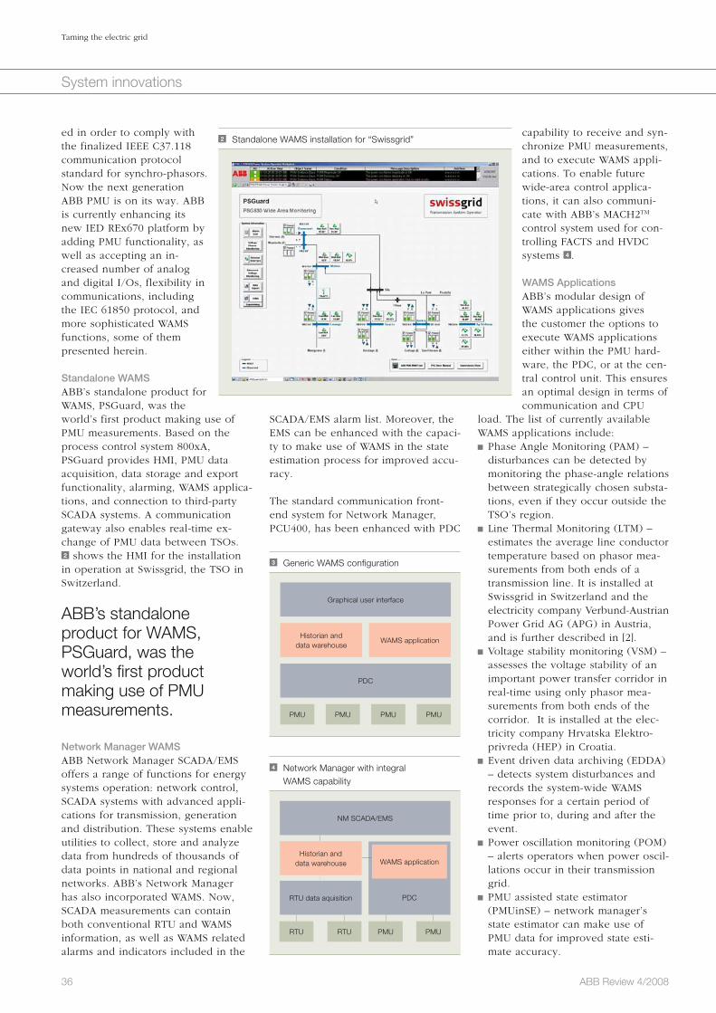
36 ABB Review 4/2008
Taming the electric grid
System innovations
capability to receive and syn-chronize PMU measurements, and to execute WAMS appli-cations. To enable future wide-area control applica-tions, it can also communi-cate with ABB’s MACH2TM control system used for con-trolling FACTS and HVDC systems 4 .
WAMS ApplicationsABB’s modular design of WAMS applications gives the customer the options to execute WAMS applications either within the PMU hard-ware, the PDC, or at the cen-tral control unit. This ensures an optimal design in terms of communication and CPU
load. The list of currently available WAMS applications include: Phase Angle Monitoring (PAM) – disturbances can be detected by monitoring the phase-angle relations between strategically chosen substa-tions, even if they occur outside the TSO’s region.
Line Thermal Monitoring (LTM) – estimates the average line conductor temperature based on phasor mea-surements from both ends of a transmission line. It is installed at Swissgrid in Switzerland and the electricity company Verbund-Austrian Power Grid AG (APG) in Austria, and is further described in [2].
Voltage stability monitoring (VSM) – assesses the voltage stability of an important power transfer corridor in real-time using only phasor mea-surements from both ends of the corridor. It is installed at the elec-tricity company Hrvatska Elektro-privreda (HEP) in Croatia.
Event driven data archiving (EDDA) – detects system disturbances and records the system-wide WAMS responses for a certain period of time prior to, during and after the event.
Power oscillation monitoring (POM) – alerts operators when power oscil-lations occur in their transmission grid.
PMU assisted state estimator (PMUinSE) – network manager’s state estimator can make use of PMU data for improved state esti-mate accuracy.
SCADA/EMS alarm list. Moreover, the EMS can be enhanced with the capaci-ty to make use of WAMS in the state estimation process for improved accu-racy.
The standard communication front-end system for Network Manager, PCU400, has been enhanced with PDC
ed in order to comply with the finalized IEEE C37.118 communication protocol standard for synchro-phasors. Now the next generation ABB PMU is on its way. ABB is currently enhancing its new IED REx670 platform by adding PMU functionality, as well as accepting an in-creased number of analog and digital I/Os, flexibility in communications, including the IEC 61850 protocol, and more sophisticated WAMS functions, some of them presented herein.
Standalone WAMSABB’s standalone product for WAMS, PSGuard, was the world’s first product making use of PMU measurements. Based on the process control system 800xA, PSGuard provides HMI, PMU data acquisition, data storage and export functionality, alarming, WAMS applica-tions, and connection to third-party SCADA systems. A communication gateway also enables real-time ex-change of PMU data between TSOs. 2 shows the HMI for the installation in operation at Swissgrid, the TSO in Switzerland.
ABB’s standalone product for WAMS, PSGuard, was the world’s first product making use of PMU measurements.
Network Manager WAMSABB Network Manager SCADA/EMS offers a range of functions for energy systems operation: network control, SCADA systems with advanced appli-cations for transmission, generation and distribution. These systems enable utilities to collect, store and analyze data from hundreds of thousands of data points in national and regional networks. ABB’s Network Manager has also incorporated WAMS. Now, SCADA measurements can contain both conventional RTU and WAMS information, as well as WAMS related alarms and indicators included in the
2 Standalone WAMS installation for “Swissgrid”
3 Generic WAMS configuration
Graphical user interface
PDC
Historian and data warehouse
PMU PMU PMU PMU
WAMS application
4 Network Manager with integral WAMS capability
PDC
RTU RTU PMU PMU
WAMS application
NM SCADA/EMS
Historian and data warehouse
RTU data aquisition
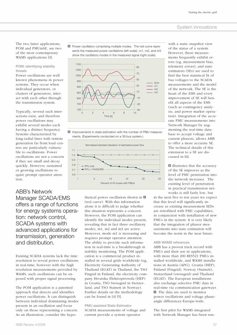
37ABB Review 4/2008
Taming the electric grid
System innovations
with a static snapshot view of the status of a system. However, these measure-ments frequently exhibit er-rors (eg, measurement bias, telemetry errors), and state estimators (SEs) are used to find the best statistical fit of bus voltages to the SCADA measurements and the model of the network. The SE is the heart of the EMS and every improvement of SE will ben-efit all aspects of the EMS (such as contingency analy-sis, and power market opera-tion). Integration of the accu-rate PMU measurements into Network Manager by aug-menting the real-time data-base to accept voltage and current phasors, allows ABB to offer a more accurate SE. The technical details of this extension to a SE are dis-cussed in [6].
6 illustrates that the accuracy of the SE improves as the level of PMU penetration into the network increases. The existing level of penetration in practical transmission net-works is still fairly low, but
in the next five to ten years we expect that this level will significantly in-crease as existing measurement IEDs are retrofitted with PMU capabilities, in conjunction with installation of new PMUs in the system. It is very likely that the integration of phasor mea-surements into state estimation will become the norm in the near future.
ABB WAMS referencesABB has a proven track record with PMUs and their use in applications, with more than 200 RES521 PMUs in-stalled worldwide, and WAMS installa-tions in Austria (APG), Croatia (HEP), Finland (Fingrid), Norway (Statnett), Switzerland (swissgrid) and Thailand (EGAT). The European installations also exchange selective PMU data in real-time via communication gateways 7 . The data are used to monitor power oscillations and voltage phase-angle differences Europe-wide.
The first pilot for WAMS integrated with Network Manager has been run-
thetical power oscillation shown in 5 (red curve). With this information alone it is difficult to judge whether this situation represents a concern. However, the POM application can identify the individual modes present, revealing that in fact three oscillatory modes, m1, m2 and m3 are active. Moreover, mode m1 is increasing and requires prompt operator attention. The ability to provide such informa-tion in real-time is a breakthrough in stability monitoring. The POM appli-cation is a commercial product in-stalled in several grids worldwide (eg, Electricity Generating Authority of Thailand (EGAT) in Thailand, the TSO Fingrid in Finland, the electricity com-pany Hrvatska Elektroprivreda (HEP) in Croatia, TSO Swissgrid in Switzer-land, and TSO Statnett in Norway). Further details on the methodology can be found in [4] [5].
PMU assisted State EstimatorSCADA measurements of voltage and current provide a system operator
The two latter applications, POM and PMUinSE, are two of the most contemporary WAMS applications [3].
POM: identifying stability threatsPower oscillations are well known phenomena in power systems. They occur when individual generators, or clusters of generators, inter-act with each other through the transmission system.
Typically, several such inter-actions exist, and therefore power oscillations may exhibit several modes each having a distinct frequency. Systems characterized by long-radial lines with remote generation far from load cen-ters are particularly vulnera-ble to oscillations. Power oscillations are not a concern if they are small and decay quickly. However, sustained or growing oscillations re-quire prompt operator atten-tion.
ABB’s Network Manager SCADA/EMS offers a range of functions for energy systems opera-tion: network control, SCADA systems with advanced applications for trans mission, generation and distribution.
Existing SCADA systems lack the time resolution to reveal power oscillations in real-time, however with the high resolution measurements provided by WAMS, such oscillations can be ex-posed with proper signal processing.
The POM application is a patented approach that detects and identifies power oscillations. It can distinguish between individual dominating modes present in an oscillation and focus only on those representing a concern. As an illustration, consider the hypo-
5 Power oscillation comprising multiple modes. The red curve repre-sents the measured power oscillations (left scale). m1, m2, and m3 show the oscillatory modes in the measured signal (right scale).
1100
1050
1000
950
900
850
800
750
7000 2 4 6 8 10
-50
-30
-10
10
30
50Summ1m2m3
70
90
Time [s]
6 Improvements in state estimation with the number of PMU measure-ments. (Experiments conducted on a 39 bus system.)
1.1
1.0
0.9
0.8
0.7
0.6
1 5 10 15 20 25
Percent of HV buses with PMUs
Normalized standard deviation of estimated power flow
RTU only RTU + PHASORS

38 ABB Review 4/2008
Taming the electric grid
System innovations
fault analyses. Further details on the Network Manager WAMS pilot at Statnett can be found in [7].
In Europe, the SmartGrids initiative is developing a road map to deploy the electricity networks of the future, and WAMS is one of the key technologies considered.
Oscillation incidentA very illustrative case of power oscil-lations was recorded by the WAMS in operation at Statnett on August 14, 2007. On this day, a combination of line outage and unfavorable genera-tion dispatch led to sustained power oscillations in the Norwegian trans-mission system. The corresponding POM signals are shown in 8 . 8a shows the measured power flow from Nor-way to Sweden. The frequency of the most significant oscillatory mode detected is shown in 8c . It shows that the 0.5 Hz mode, which is a well known characteristic mode for the Nordic power system, has been excit-ed and is dominant in the signal. 8b shows the amplitude of this mode. The amplitude increases drastically, approximately 35 seconds into the sequence, when the oscillations ap-peared. The damping of this mode is shown in 8d , and drops from a satis-factory value to a negative value, then stays very low while the oscillations are present. The POM output signals can be combined in SCADA to gener-ate simple operator signaling when oscillations appear.
It is also worth noting that even though the cause of the power oscilla-tions was in a location approximately midway between the Fardal and Nedre Røssåga stations, ie, quite far away from the southern interface to Sweden, they are easily seen by the POM application. The stability of the entire grid can therefore be observed by strategic deployment of PMUs and POM applications monitoring key sub-stations. A more detailed discussion of this event can be found in [8].
the lines emanating from the Hasle substation towards Sweden. Using National Instruments Labview soft-ware, Statnett have also developed their own analysis application to simultaneously access SCADA, WAMS and transient fault recorder data, pro-viding a very powerful tool for post
ning at the Norwegian TSO (Statnett) since 2007, where PMUs are installed at four different substations, as shown in 9 . In addition, PMU measurements from Finland are collected via the communication gateway running at Fingrid. The PDC at Statnett applies POM analysis of the power flow on
7 WAMS data exchange in Europe
Switzerland Austria
Croatia
Additional European PMUs
Slovenia
LegendPSGuard 830/850Phasor DataConcentrator
PSGuard CommunicationGateway
CommunicationGateway
CommunicationGateway
PDC 1PDC 1
PDC 1
PDC 2PDC 2
CommunicationGateway
ABB PhasorMeasurementUnit RES 521
Italy
Greece
Secure Inter-TSOCommunication Network
PMU protocols IEEE 1344-1995and IEEE C37.118
8 POM responses to August 14, 2007 power oscillation event.
Power flow Hasle towards Sweden2200 80
400.8
2100 60
300.7
2000 40
200.6
1900 20
100.5
1800 0
0
0.4
-10
0.3
0.20 0
00
50 50
5050
100 100
100100
150 150
150150
(WM
) pow
er
(WM
) pow
er
Freq
uenc
y (H
z)
Dam
ping
(%)
Damping of 0.5 Hz mode
3% alarm limit
Frequency of main oscilatory mode (0.5 Hz)
Amplitude of 0.5 Hz mode
Time (seconds)
Time (seconds)Time (seconds)
Time (seconds)
a
c
b
d

39ABB Review 4/2008
Taming the electric grid
System innovations
through continued research and de-velopment to push the envelope of technologies, such as WAMS, that can facilitate enhanced monitoring and control of electric transmission sys-tems. Due to this early and ongoing commitment, ABB offers the most complete portfolio, providing PMUs, PDCs and WAMS – all integrated with Network Manager SCADA – as well as standalone systems, and solutions integrated with third-party SCADA systems.
Albert Leirbukt
ABB Power Systems
Oslo, Norway
Ernst Scholtz
ABB Corporate Research
Raleigh, NC, USA
Sergiu Paduraru
ABB Power Systems
Västeras, Sweden
(NASPI) is another U.S. led initiative that aims to increase the deployment of WAMS and accelerate the develop-ment of new applications in order to improve operational reliability.
ABB’s complete portfolio offers PMUs, PDCs, and WAMS both integrated with Network Manager SCADA, standalonesystems or solutions integrated with third-party SCADA systems.ABB have long been pioneers in the WAMS arena, and are committed
The way forwardThe industry has started to realize the benefits and hence started to embrace WAMS technology. Thus, there is still tremendous development potential in the use of synchronized measure-ments in electric transmission system operation. Several ongoing broad ini-tiatives will help to advance this tech-nology. In Europe, the SmartGrids initiative is developing a roadmap to deploy the electricity networks of the future, and WAMS is one of the key technologies considered. In the U.S., the Electric Power Research Institute (EPRI) runs an initiative aiming to provide a technical foundation to enable massive deployment of such concepts (Intelligrid). The North American Synchro-phasor Initiative
Acknowledgment
The authors would like to thank Mats Larsson, Petr Korba, Reynaldo Nuqui, Neela Mayur, Michael Geiger, Hugo Meier for their contribution to this article.
References
[1] Novosel, D., Madani, V., Bhargava, B., Vu, K., Cole J. (2008) Dawn of the Grid Synchronization. IEEE power & energy magazine January/February.
[2] Weibel, M., Sattinger, W., Steinegger, U., Zima, M., Biedenbach G. (2006) Overhead Line Temperature Monitoring Pilot Project. CIGRE Session.
[3] North American Synchro-Phasor Initiative Meeting June 11–12, 2008, Bellevue, Washington, http://www.naspi.org/meetings/workgroup/workgroup.stm
[4] Korba, P. (2007) Real-Time Monitoring of Electromechanical Oscillations in Power Systems. IEE Proceedings of Generation Transmission and Distribution. 1/80-88.
[5] Turunen, J., Larsson, M., Korba, P., Jyrinsalo, J., Haarla, L. (2008) Experiences and Future Plans in Monitoring the Inter-area Power Oscillation Damping.
IEEE PES General Meeting.
[6] Scholtz, E., Nuqui, R. F., Finney, J. D., Larsson, M., Subramanian, M., Lin G. Estimation of Real-Time Power System Quantities using Time-Synchronized
Measurements. US Patent Application 11/609,393
[7] Leirbukt, A., BreidablikJ, Ø., Gjerde, O., Korba, P., Naccarino, J., Uhlenand, K., Vormedal, L. K. (2008) Deployment of a SCADA Integrated Wide Area Monitoring
System. IEEE T&D Latin America.
[8] Uhlen, K., Warland, L., Gjerde, J. O., Breidablik, Ø., Uusitalo, M., Leirbukt, A., Korba P. (2008) Monitoring Amplitude, Frequency and Damping of Power System
Oscillations with PMU Measurements. IEEE PES General Meeting.
8 PMU substations

40
System innovations
ABB Review 4/2008
The future is nowLinking up the world’s largest offshore wind-farm area with HVDC transmission Jochen Kreusel
Renewable energies that provide electricity without emitting any CO2 are rapidly advancing all over the globe. As one of the major industrialized nations, Germany is pursuing a highly ambitious strategy: The target is to increase the proportion of renewable energies from today’s 13 percent to as much as 25 to 30 percent by 2030. There is still a long way to go, and the key to achieving this target is out at sea – in Germany this means the high seas. Offshore wind energy has been earmarked to fill a large portion of the gap. In late 2006, a vital statutory precondition for this was put in place; meanwhile wind farms with a total rating of more than 15,000 MW are being planned for the North and Baltic Seas, with the first of them already in the implementation phase. But how is the electricity going to reach dry land and the actual consumers?

41ABB Review 4/2008
The future is now
System innovations
tor, or SVC). In the case of wind-farm links, this means that reactive power can be provided for the offshore network inside a wind farm, and that the voltage stability at the connection point can be supported. This enables the high power levels of the offshore wind farms to be fed into the network (which in coastal regions is often weak) without impairing system compatibility.
Black-start capabilityThe transmission system can be started from the de-ener-gized state, eg, if the wind
has not blown at all.
Reduced filter requirement with concomitant space savingsIn comparison to traditional HVDC transmission, the offshore platform can be significantly smaller in size and designed for considerably less weight.
For an offshore wind farm, the lack of what is called “black-start capability” constitutes a fundamental problem.
A world recordAnother advantage of self-commutated HVDC transmission is that it can be combined with simple, lightweight, eco-friendly polymer cables, since the voltage peaks in the DC link encoun-tered in traditional HVDC transmission
The power transistors used in self-commutated HVDC applications are, in contrast to the thyristors used in traditional systems, able to not only switch electricity on, but also off again. This means they can be utilized for pulse-width modulation, which in comparison to traditional HVDC tech-nology leads to much better approxi-mation of the sinusoidal voltage char-acteristics and thus to a much reduced filter requirement. Three properties combine to make it an ideal solution for linking up offshore wind farms:
Unrestricted reactive power provisionThe converters of an HVDC Light sys-tem can provide any active/reactive power combination within their design limits, swiftly and without the gradations required in traditional systems 2 . They therefore offer the full functionality of a controllable compensator at both ends of a trans-mission system (static VAR compensa-
With this question, Ger-many is entering virgin
territory, since the offshore wind farms already installed in other countries are all sig-nificantly nearer to the coast than the areas selected in the North Sea. Because of the need to protect the tidal shal-lows, distances of more than 100 km must in some cases be overcome using subma-rine cables 1 . The use of three-phase cables is finan-cially and technically unsuit-able for distances of this magnitude. Thus, the subma-rine cable links installed in Scandinavia, for example, and between Scandinavia and Conti-nental Europe, are executed as high-voltage direct current (HVDC) sys-tems. However, it is not possible sim-ply to adopt this field-proven solution for network linkage of offshore wind farms.
Classical thyristor-based HVDC trans-mission needs short-circuit power for commutation (ie, turning off the thy-ristors), which has to be provided by the surrounding networks. This is in-dubitably assured when it comes to linking up the interconnected net-works of Scandinavia and Continental Europe, and for large-scale long-dis-tance power transmission in China and South America, the most impor-tant HVDC applications hitherto. For an offshore wind farm, which firstly does not possess a powerful network and secondly also has to be capable of starting up from a de-energized state, the lack of what is called “black-start capability” constitutes a fundamental problem.
HVDC Light® for offshore wind energy The technical innovation that solves this problem is called self-commutated HVDC transmission. It is based on state-of-the-art power transistors (insulated -gate bipolar transistors, or IGBTs), and was premiered in the mid-1990s by ABB under the name of HVDC Light; it is meanwhile being used in numerous projects with steadily increasing ratings. Today, system ratings of up to 1,100 MW can be implemented using this tech-nology.
1 Planned offshore wind farms in the German North Sea
Offshore wind farms
Approved
External data sourceElsam A/S (Denmark)
Planned
The Netherlands
Denmark
2 P-Q diagram showing a traditional HVDC system a and the self-commutated HVDC Light b . HVDC Light is able to control every point of the four quadrants swiftly and continuously.
HVDC classic HVDC Light
-1.0 -1.01.0 1.0
P
Filterconverter total
Filterconverter totalP
Q Q
a b

42 ABB Review 4/2008
The future is now
System innovations
fer platform, on which the 30 kV ca-bles arriving from the wind-energy in-stallations are grouped together. Using relatively short high-voltage three-phase cables, these platforms are in turn connected to the E.ON platforms – the power sockets – where the cur-rent is converted into DC. At the same time, the converter station is able to cover the reactive-power requirements of the offshore network. Several of the E.ON platforms and several HVDC Light systems can be connected at sea using a three-phase busbar, which en-ables additional transmission systems to be successively integrated in paral-lel to the present one as the network link is expanded in the future.
On completion of the wind-farm projects currently underway in the Borkum 2 cluster, the North Sea wind-farm network will have a rating of approximately 6,300 MW.
Network design enhancement on land The solution has thus been found for transporting the electricity generated at sea to the mainland. But this does not yet mean that all impediments to achieving the German federal govern-
responsibility for network linkage of the offshore wind farms with the transmission network operators, the network link can be optimized irre-spective of the particular wind farms involved [2]. Several “seaborne power sockets,” to which the completed wind farms can be connected, will ac-cordingly be provided for the Borkum 2 cluster. ABB has been asked to sup-ply the first of these power sockets, featuring an HVDC Light system rated at 400 MW. 128 km of submarine cable and 75 km of underground cable will connect this first joint node for several wind farms to the transmission grid at the Diele transformer substation 3 .
In June 2008, work began on laying the underground cables, dimensioned for a DC link voltage of ± 150 kV 4 . The very small diameter of the cables – about 8 cm, typical for HVDC Light systems – can be clearly seen. The cables are laid on land in 750 m sec-tions at a depth of about 90 cm in existing soil material, and are protect-ed by a plastic cover.
By 2009, the network link will already have gone into operation. This means it will have been completed just as swiftly as the Estlink between Finland and Estonia. The plan is to gradually expand this initial link as the wind-farm area is upsized in the future. 5 shows the basic concept involved for network linkage of the wind-farm area pursued by the network operator E.ON in its own sphere of responsibil-ity. Each wind farm has its own trans-
do not occur. In addition, the HVDC converters are nowadays designed in a modularized, largely prefabricated construction, enabling the network links required for the planned off-shore wind farms to be implemented with sufficient celerity. This has most recently been demonstrated with the Estlink between Finland and Estonia inaugurated in late 2006, which was completed in just under 20 months – a world record for an HVDC transmis-sion system [1].
Self-commutated HVDC transmission is based on state-of-the-art power transistors and was pre-miered in the mid-1990s by ABB under the name of HVDC Light.
Green light for the North Sea network By the summer of 2007, all technical preconditions for beginning construc-tion of the offshore network in the North Sea had been met. E.ON Netz then put the first stage out to tender for the first link to a commercial off-shore wind-farm area in the North Sea – the Borkum 2 cluster. On comple-tion of the wind-farm projects current-ly underway in this area, the North Sea wind-farm network will have a rating of approximately 6,300 MW.
Since the German Infrastructure Plan-ning Acceleration Act1) places the
3 Network link between the cluster Borkum 2 offshore wind-farm area and the German grid
Rating 400 MW
Wind-farm clusterBorkum 2
Offshore wind-park clusterBorkum 2
Largest offshore wind park in the world
Largest distance from mainland
First grid connection with direct current in Germany
Sylt DENMARK
128 km sea cable
BorkumNorden
Emden
Substation Diele
Bremer-haven
CuxhavenScharhörn
Helgoland
Wilhelms-haven
75 kmland cable
NETHERLANDS
Tailwind for grid reliability
4 Laying the first sections of cable (operating voltage 150 kV, transmis-sion rating 400 MW) in Aurich County, Germany in June 2008
Footnote1) Infrastrukturplanungsbeschleunigungsgesetz
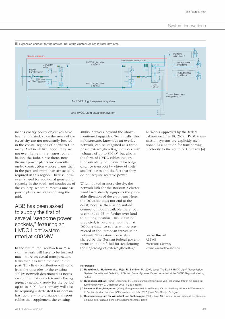
43ABB Review 4/2008
The future is now
System innovations
networks approved by the federal cabinet on June 18, 2008, HVDC trans-mission systems are explicitly men-tioned as a solution for transporting electricity to the south of Germany [4].
Jochen Kreusel
ABB AG
Mannheim, Germany
400 kV network beyond the above-mentioned upgrades. Technically, this infrastructure, known as an overlay network, can be imagined as a three-phase extra-high-voltage network with voltages of up to 800 kV, but also in the form of HVDC cables that are fundamentally predestined for long-distance transport by virtue of their smaller losses and the fact that they do not require reactive power.
When looked at more closely, the network link for the Borkum 2 cluster wind farm already signposts the prob-able direction of development: Here, the DC cable does not end at the coast, because there is no suitable connection point available there, but is continued 75 km further over land to a fitting location. This, it can be predicted, is precisely how the first DC long-distance cables will be pre-miered in the European transmission network. This estimation is also shared by the German federal govern-ment: In the draft bill for accelerating the upgrading of extra-high-voltage
ment’s energy policy objectives have been eliminated, since the users of the electricity are not necessarily located in the coastal regions of northern Ger-many. And in all likelihood, they are not even living in the nearest conur-bation, the Ruhr, since there, new thermal power plants are currently under construction – more plants than in the past and more than are actually required in this region. There is, how-ever, a need for additional generating capacity in the south and southwest of the country, where numerous nuclear power plants are still supplying the grid.
ABB has been asked to supply the first of several “seaborne power sockets,” featuring an HVDC Light system rated at 400 MW.
In the future, the German transmis-sion network will have to be focused much more on actual transportation tasks than has been the case in the past. This first contribution will come from the upgrades to the existing 400 kV network determined as neces-sary in the first dena (German Energy Agency) network study for the period up to 2015 [3]. But Germany will also be requiring a dedicated transport in-frastructure – long-distance transport cables that supplement the existing
5 Expansion concept for the network link of the cluster Borkum 2 wind-farm area
AC filterPhase reactor
Convertervalve
HVDC Light cable+ 150 kV
HVDC Light cable+ 150 kV GIS
154 kV
Three-phase high- voltage busbar
2nd additionalwind farm
1st additionalwind farm
Platform wind farm 1
Power transformator
Scope of delivery
Offshore converter station I
1st HVDC Light expansion system
2nd HVDC Light expansion system
References
[1] Ronström, L., Hoffstein M.L., Pajo, R., Lahtinen M. (2007, June). The Estlink HVDC Light® Transmission
System, Security and Reliability of Electric Power Systems. Paper presented at the CIGRÉ Regional Meeting,
Tallinn.
[2] Bundesgesetzblatt. (2006, December 9). Gesetz zur Beschleunigung von Planungsverfahren für Infrastruk-
turvorhaben vom 9. Dezember 2006. I, 2833, Berlin.
[3] Deutsche Energie-Agentur. (2004). Energiewirtschaftliche Planung für die Netzintegration von Windenergie
in Deutschland an Land und Offshore bis zum Jahr 2020 (dena Grid Study), Cologne.
[4] Bundesministerium für Wirtschaft und Technologie. (2008, June 18). Entwurf eines Gesetzes zur Beschle-
unigung des Ausbaus der Höchstspannungsnetze. Berlin.

44 ABB Review 4/2008
System innovations
Safety is paramount in the operation of any plant. It goes without saying that any threat to humans is unac-ceptable. The implications of safety can, however, reach beyond the basic protection of people and equipment. For example the negative publicity over a safety-related incident can have far-reaching repercussions for the company involved and in some cases even for the entire industry.
With the increasing complexity of pro-cesses, and different manufacturers
Integrated safetyIntegrated safety systems: keeping it safe Kristian Olsson
supplying different systems within the plant, ensuring an overall high level of safety can be challenging. ABB believes that the safety system of the future is no longer an “add-on”, that is designed and supplied separately from the rest of the plant or process, but an integral part of it.
ABB’s Industrial IT System 800xA High Integrity safety system is an integral part of the company’s System 800xA offering of control s ystems.

45ABB Review 4/2008
Integrated safety
System innovations
ABB in safety systemsHaving begun development of its first safety system in 1978 (which went online at the Statfjord B platform in the North Sea in 1979), ABB has gained almost 30 years of experience with safety systems. ABB enjoys a unique position among safety suppli-ers due to an early strong presence on the Norwegian continental shelf, where national safety standards were developed and implemented long before more recent international stan-dards were formulated and accepted.
During its long presence in the mar-ket, ABB has produced several gener-ations of safety systems characterized by varying technical solutions. These range from the Safeguard family of systems developed in Norway, through the triple modular redundan-cy (TMR) type Plantguard system to the most recent addition: the modular and scalable 800xA High Integrity sys-tem, which is part of the System 800xA portfolio.
The 800xA High Integrity system be-longs to the latest generation of inte-grated safety systems, ie, a safety sys-tem capable of being tightly integrated to a regular process-control system. ABB is proud to have been delivering integrated safety systems for close to 25 years, with experience dating back to the implementation of an integrated safety system on the Gullfaks A plat-form which went online in 1984.
By nature, a safety system constitutes a critical part of any plant-automation system and as such can require access to qualified support at any time – re-gardless of its location in the world. ABB’s highly developed local pres-ence on all continents with skilled safety engineers offers end users criti-cal around-the-clock support that helps maximize plant uptime. Addi-tional customer confidence is gained through a global process to achieve third-party accredited certification by TÜV Rheinland, for compliance to IEC 61508 and IEC 61511, currently underway at 16 local ABB system delivery and support organizations worldwide [3]. ABB safety system installations in well over 45 countries around the world are a further testi-mony to a strong local presence and
boiler/burner management systems to hazardous-materials handling and as-set-protection applications.
By nature, a safety system constitutes a critical part of any plant-automation system.
Besides the overall drive towards more stringent regulations and the growing acceptance of the IEC 61508 / IEC 61511 standards, broader de-ployment of safety systems is primari-ly motivated by increasing concern in the public domain for safety and envi-ronmental aspects (resulting in reputa-tional risk for the operator) and as a means to reduce premiums (when in-surance companies use such standards to evaluate and benchmark a plant’s risk-reduction measures).
Growth projections by the ARC advisory group indicate that the
global safety systems market will continue to grow by approximately 12.5 percent annually until 2012 [1]. The booming demand comes primarily from the oil & gas and petrochemical segments, and is further augmented by the tightening of safety regulations and the worldwide adoption of IEC 61508 and IEC 61511 as “best practices” in non-traditional safety industry segments.
Safety systems are no longer exclu-sively deployed in traditional markets and applications such as fire and gas applications or in emergency shut-down systems in the oil & gas and the chemical industry. Demand is increas-ing in other sectors such as the power generation, pulp & paper, mining and even semiconductor industries, with applications ranging from traditional

46 ABB Review 4/2008
Integrated safety
System innovations
guidelines and best practices on developing and optimiz-ing their safety offering. It also offers end-users the means to efficiently bench-mark system risk reduction capabilities, albeit without absolving them from their final responsibility for the safe operation of the plant. By requesting an SIL2- or SIL3-rated safety system, an end-user is getting a clearly defined level of risk reduc-tion.2)
Safety systems were histori-cally designed as completely standalone systems in which risk reduction was ensured
by hardware redundancies and the independence of the process control and safety systems. Progress in soft-ware and hardware design, as well as manufacturing techniques, provides increased hardware reliability as well as a near 100 percent diagnostic cov-erage. Safety products can today be designed to achieve reliability levels meeting specifications set by interna-tional standards without resorting to complex hardware-redundancy schemes. As a result, simplex and duplex 1 modular and scalable inte-grated control and safety systems
and end users have begun to fully appreciate the possibilities and limita-tions of such systems, the pressure for their further enhancement has risen. End users in pursuit of such goals as reduced cost of ownership, improved operational excellence and increased engineering efficiencies are driving a transition from traditional stand-alone safety system practices towards an inte grated approach, seemingly in agreement with independent research bureaus such as ARC [4]. Simultane-ously, a strong influence from interna-tional standards and a growing safety concern among various third-party in-terest groups is driving safety-product and system suppliers to incorporate new ideas and requirements, while maintaining a vigilant approach to compliance issues.
The framework of IEC 61508 and IEC61511 provide suppliers with clear
well-distributed competence throughout the organization.
As a supplier of safety prod-ucts, ABB is facing a chal-lenging balancing act in striv-ing to further develop its safety-systems offering to better meet customer demand and enhance customer value while at the same time main-taining a stern view on com-pliance issues. For ABB, safe-ty remains paramount. Devel-opment techniques utilizing the V-model1) , strict coding guidelines, separate develop-ment teams (ie, diverse im-plementation) and a strategy of diverse technologies en-sure a structured approach throughout the entire development process.
Safety products can today be designed to achieve reliability levels meeting specifications set by international stan-dards without resorting to complex hardware-redundancy schemes.
Continuous supervision by the third-party independent certification organi-zation TÜV provides additional end-user confidence.
Converging market requirements Over recent years, as the implementa-tion of safety systems has become in-creasingly frequent – or mainstream –
1 Simplex and duplex safety systems
Simplex SIL 2 Safety System
Duplex SIL 2 High Avail-ability Safety SystemS880 I/O
Footnotes1) The V-model is a project management structure for
IT-system development. The name derives from the
commonly used V-shaped depiction, with definition
steps along one leg and the corresponding testing
steps on the other.2) Safety integrity level (SIL) is a relative level of risk-
reduction, with SIL3 being the highest level typically
found in the process industry

47ABB Review 4/2008
Integrated safety
System innovations
units have been delivered to date in more than 35 coun-tries.
Based on further develop-ments released during 2008, the 800xA High Integrity platform is now SIL3 compli-ant, with certification being expected in late 2008. This will further enhance its range of application in the market-place. Although the majority of safety-system applications only require a SIL2 rating, it is common practice among end-users to nevertheless specify an SIL3-certified system to ensure flexibility should a SIL3 requirement arise in the future. The 800xA High Integrity belongs to the newest generation of scalable and modular safety systems.
The latest SIL3-compliant version is based on a system configuration known as a 1oo2D system where the “D” stands for diagnostic, indicating the significant internal diagnostic mea-sures in place to detect failures. The system is SIL3 compliant in a single configuration. Redundant configura-tions are used to increase availability, and safety is ensured regardless of the configuration.
It should be noted that while 800xA High Integrity is an integrated safety system, this is only one of several possible configurations. The system has been designed from the outset to be able to operate as a standalone safety system, and integration to a process-control system is only one of the possible options available to an end-user. Based on current market trends, more and more end-users are moving towards integrated systems and looking to tap into the potential benefits. Based on the large common-alities to – and true integration with – the process-control portions of the overall System 800xA product family, end users of 800xA High Integrity are able to enjoy significantly reduced cost of ownership as several key cost drivers are removed or reduced when implementing integrated safety systems.
tional safety policies. Properly inte-grated safety systems can offer ways to not only reduce cost of ownership, but also, more importantly, to ensure safe operation of the system. Engi-neering efficiencies, improved under-standing of the system and support can have a direct impact on bottom-line performance and safe plant oper-ation.
Despite increased depen-dence on ever more powerful process-control and safety systems, the human aspect remains an integral part of any plant’s operation.
Many suppliers of major process con-trol systems offer integrated safety systems to complement their DCS3) offering. However, there are subtle, but important, differences in the levels of integration that are supported [7]. Some solutions are more integrated than others, offering a differing scope for reduction in cost of ownership.
System 800xA High IntegrityThe SIL2-certified 800xA High Integri-ty controller (logic solver) and associ-ated I/O subsystem was released in late 2004. More than 1,000 controller
have been developed that do not compromise safety or continuous plant operation [5]. While still fully compliant to international safety standards, these systems have greater commonalities with regular process-control systems and are hence well suited to inte-grated solutions. As a result, safety systems are now less likely to be purchased sepa-rately but are rather becom-ing critical and integrated components of complete automation solutions. This market trend is a prime dif-ferentiator setting suppliers of integrated safety systems apart from more traditional providers of separate offer-ings.
Despite increased depen-dence on ever more powerful pro-cess-control and safety systems, the human aspect remains an integral part of any plant’s operation. Operators, engineers and maintenance personnel constitute important contributors to overall plant risk reduction [6]. Conse-quently, the operational aspects of safety systems is an area currently being scrutinized. One business driver for this effort is a focus on reductions in operational costs throughout the system’s lifecycle. However, while po-tential savings in operational cost are substantial, it is often easy to forget that there are also real safety concerns fueling this discussion. In an industry struggling with increasing complexity in its systems, a large number of sup-pliers contributing to any given plant combined with an aging competence pool, imply an increase in the risk of safety-critical mistakes. An obvious countermeasure is a reduction in both system complexity and the number of systems employed – enter integrated and similar process-control and safety systems. Many new safety systems offer an in-creased level of integration and scal-ability. These are designed to facilitate optimized system design, efficient engineering, operations and mainte-nance while also allowing the user to tailor system design and integration concepts to meet plant-specific func-
Footnote3) DCS: distributed control system
48 ABB Review 4/2008
Integrated safety
System innovations
and processes in all phases from plan-ning, through operation to decommis-sioning. Consulting capabilities cover all project and product phases and the full scope of safety issues from the management level to the shop floor Factbox .
A truly integrated solutionABB, with its almost 30 years of expe-rience in the industry and a highly competitive safety systems offering, is ideally placed to meet customer re-quirements and expectations for the new generation of integrated safety systems. System 800xA, featuring the 800xA High Integrity safety system constitutes a comprehensive and cohesive plant automation solution for all applications; a truly-integrated safety system where functionality and safety have been perfectly balanced to allow end-users to minimize overall cost of ownership without compromis-ing safety.
Kristian Olsson
ABB AS, Safety Center of Excellence
Oslo, Norway
References
[1] Safety and Critical Control System Worldwide
Outlook, Market Analysis and Forecast Through
2012, 2008, ARC Advisory Group.
[2] Complete Control And Safety For Statoil Sleipner
Platform, ABB Project Profile 3BNP000565R0001.
[3] Nunns, S. R., Prew, R. W. (2008). Safe and
sound. ABB Review Special Report Process Auto-
mation Services & Capabilities, 30–34.
[4] Business Issues Driving Safety Systems Integra-
tion, 2006, ARC White Paper, ARC Advisory
Group.
[5] Reduce Risk With A State-of-the-Art Safety Instru-
mented System, 2004, ARC White Paper, ARC
Advisory Group.
[6] Out Of Control: Why Control Systems Go Wrong
And How To Prevent Failure, UK Health and Safety
Executive.
[7] Business Issues Driving Safety Systems Integra-
tion, 2006, ARC White Paper, ARC Advisory
Group.
An area increasingly being explored is the possibility of leveraging top-level capabilities such as the information management or asset management functionality on System 800xA, and implementing these powerful tools in a safety context. Furthermore, it should not be forgotten that safety is part of any automation life-cycle plan where an existing process-control sys-tem is gradually upgraded and evolved to use more System 800xA components. Many existing plants are coming under pressure to implement risk-reduction measures in line with current standards, or can benefit from lowered insurance premiums by in-cluding safety systems into their over-all automation solution. 800xA High Integrity is ideally suited to be added to existing plant automation solutions whenever System 800xA is introduced.
A one-stop shopWhile controllers and I/O subsystems typically come to mind when discuss-ing a safety system, it is important to remember the many other compo-nents that are involved in any safety-critical loop; from the initiating ele-ment (the instrument) to the final ele-ment (the actuator) and everything in between.
ABB’s total offering includes safety-certified instruments, positioners as well as expertise built during decades of safety-system implementations.
ABB can provide a wide range of SIL-rated sensors, valve positioners and actuators. Various solutions are avail-able: These range from high-integrity transmitters with full redundancy de-signed and certified by TÜV according to IEC 61508 requirements, to stan-dard transmitters with enhanced inter-nal diagnostics to improve reliability. The positioners are available with a shutdown module allowing the con-trol action to be overruled if required. All of these possibilities include third-party calculations and evaluations of safety performance to enable loop risk reduction assessments.
The growing ABB Global Consulting organization considers safety consult-ing a key offering and is continuously working to meet customer require-ments, addressing industrial plants
Engineering time and cost is lowered through a common engineering envi-ronment for process control and safety, enabling more efficient work proce-dures throughout the system’s life cycle. These range from initial system and application engineering to commis-sioning and subsequent modifications as the system is tuned and possibly expanded to meet future requirements.
Supported by a common sequence of event- and alarm-handling functions, operators are able to analyze hazard-ous events as they unfold and make key decisions that can potentially pre-vent or significantly mitigate the con-sequences thereof. Should an event actually take place, the same function-ality, with its millisecond accuracy, constitutes a powerful tool during post-mortem analysis.
An extensive array of built-in and con-figurable access and by-pass manage-ment functionalities allows tailored solutions for any plant to manage the interaction of both operators and maintenance crews with the safety system, without unduly influencing safe plant operation or causing un-wanted tripping.
With largely similar equipment and software tools being in place for process control and safety systems, overall training required is reduced, understanding increased and com-plexities removed – again resulting in reduced total cost of ownership throughout the lifetime of the system.
Factbox Safety-related areas covered by ABB Global Consulting
Process safety
HAZOP
Process hazard review (PHR)
Hazardous area management –
ATEX/DSEAR
Human factors
Alarm management
Functional safety
Functional safety management systems
(certified by TÜV)
SIL determination and achievement
Legacy system evolution
Safety instrumented systems (SIS)
implementation
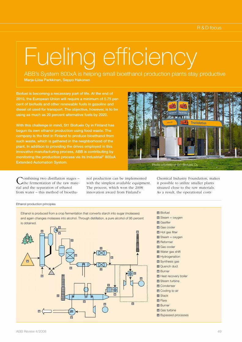
49ABB Review 4/2008
R & D focus
Combining two distillation stages – the fermentation of the raw mate-
rial and the separation of ethanol from water – this method of bioetha-
Fueling efficiencyABB’s System 800xA is helping small bioethanol production plants stay productiveMarja-Liisa Parkkinen, Seppo Hakonen
Ethanol production principles
a Biofuel
b Steam + oxygen
c Gasifier
d Gas cooler
e Hot gas filter
f Steam + oxygen
g Reformer
h Gas cooler
i Water gas shift
j Hydrogenation
k Synthesis gas
l Quench duct
m Burner
n Heat recovery boiler
o Steam turbine
p Condenser
q Cooling to air
r Stack
s Flare
t Burner
u Gas turbine
v Bypassed processes
a
b
c
d
e
f
g
h
i
j
k
l
m
no
p
q
r
s
t
u
v
Ethanol is produced from a crop fermentation that converts starch into sugar (molasses)
and again changes molasses into alcohol. Through distillation, a pure alcohol of 95 percent
is obtained.
Biofuel is becoming a necessary part of life. At the end of 2010, the European Union will require a minimum of 5.75 per-cent of biofuels and other renewable fuels in gasoline and diesel oil used for transport. The objective, however, is to be using as much as 20 percent alternative fuels by 2020.
With this challenge in mind, St1 Biofuels Oy in Finland has begun its own ethanol production using food waste. The company is the first in Finland to produce bioethanol from such waste, which is gathered in the neighborhood of the plant. In addition to providing the drives employed in this innovative manufacturing process, ABB is contributing by monitoring the production process via its IndustrialIT 800xA Extended Automation System.
nol production can be implemented with the simplest available equipment. The process, which won the 2008 innovation award from Finland’s
Chemical Industry Foundation, makes it possible to utilize smaller plants situated close to the raw materials. As a result, the operational costs
Photo courtesy of St1 Biofuels Oy
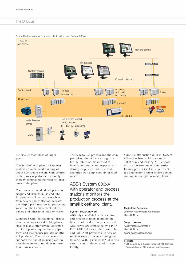
A simplified overview of a process plant built around System 800xA
System servers
Workplaces
Remote clients
Variable-speed drives
Process automation
S800 I/O
S900 I/O (Ex)
Safety
Client/server level
Control level
Device level
Fieldbus high-speed linking devices (FF HSE/HI, PB DP/PA)
MCC
Process automation and safety
Control network
Since its introduction in 2004, System 800xA has been sold to more than 4,000 new and existing ABB custom-ers in a diverse range of industries. Having proven itself in larger plants, the automation system is also demon-strating its strength in small plants.
Marja-Liisa Parkkinen
(formerly) ABB Process Automation
Helsinki, Finland
Seppo Hakonen
ABB Process Automation
Helsinki, Finland
Footnote1) St1 Biofuels Oy is the joint venture of VTT Technical
Research Center of Finland and private owners.
The easy-to-use process and the com-pact plant size make a strong case for the future of this method of bioethanol production, especially in densely populated industrialized countries with ample supply of food waste.
ABB’s System 800xA with operator and process stations monitors the production process at the small bioethanol plant.
System 800xA at workABB’s System 800xA with operator and process stations monitors the bioethanol production process, and ABB drives are connected by a PRO-FIBUS DP fieldbus to the system. In addition, ABB provides a variety of services such as commissioning and training. With System 800xA, it is also easy to control the ethanol process locally.
50 ABB Review 4/2008
Fueling efficiency
R & D focus
are smaller than those of larger plants.
The St1 Biofuels1) plant in Lappeen-ranta is an unmanned building of about 500 square meters, with control of the process performed remotely, thereby eliminating the need for oper-ators at the plant.
The company has additional plants in Närpiö and Hamina in Finland. The Lappeenranta plant produces ethanol from bakery and confectionery waste, the Närpiö plant uses potato-processing waste and the Hamina plant utilizes bakery and other food-industry waste.
Compared with the traditional distilla-tion technologies used in big plants, smaller plants offer several advantag-es. Small plants require less equip-ment and less energy per liter of etha-nol produced. The plant concept also supports the aim of reducing carbon dioxide emissions, and does not use fossil raw materials.

51ABB Review 4/2008
R & D focus
The correct jacket is requiredThe next step in outdoor instrument transformers Hoan Le
Instrument transformers convert voltage or current from high values, which are carried by the transmission and distribution networks, to lower values, which can be used by low-voltage devices. They are used for metering (energy billing and transaction purposes), protec-tion (protective relays and system protection), control (system control functions) and load surveying (economic management of industrial loads). The design and construction of the instrument transformer can be quite different depending on the applications it is used for. Generally, metering instrument transformers require high accuracy in the range of normal operating voltage and current, while protection instrument transformers require linearity in a wide range of voltages and currents.
During disturbances, such as system faults or transient over-voltages (surges or spikes), the output of the instrument transformer can be used, via a protective relay, to initiate an appropriate response. This may be to open or close a breaker, or reconfigure the system so that the disturbance is mitigated and the rest of the system remains pro-tected. Instrument transformers are the most common and economic means of detecting such disturbances. This they must do, even when subjected to a variety of outdoor environmental stresses such as ultra-violet radiation, pollutants, humidity, rain, temperature variations and salt fog. To perform well in these tough environments, ABB constantly reviews the materials used to protect its instrument transformers.

ing processes. Fully cured outdoor-grade PUR elasto-mers are easy to manufac-ture, have very good insulat-ing properties and adequate outdoor performance.
Advanced outdoor insulation Silicone rubber is widely rec-ognized today as the premier insulation material for out-door equipment due to its light weight, high-voltage resistance and superior per-formance in heavily polluted environments. Its very good outdoor performance is due to its hydrophobicity (water repelling properties). Hydrophilic (water attracting) insulating material, when
wet, tends to form a continuous film on its surface that allows conductive airborne contaminants (eg, salts, inor-ganic and organic acids) to collect and dissolve, which leads to the formation of impervious conductive films. These electrolytic films lead directly to dry-band arcing2). If the insulation is poly-meric in nature, the very high temper-atures (> 1,000 °C) of the arc thermally degrade the polymer and cause ero-sion of the insulating surface, which leads to an increase in current leak-age. With time, the dry bands propa-gate and subsequent elongation of the arc eventually leads to flashovers. The long-term performance of outdoor equipment is therefore severely affect-ed by the choice of insulating material used for encapsulation.
Water beading occurs on the surface of hydropho-bic insulating material so that conductive contami-nants roll off the surface.
Hydrophobic insulating materials pre-vent water forming a surface film. Droplets of water form beads that roll
radiation, outdoor pollutants and chemicals. Globally, CEP is the most popular outdoor insulation for medi-um-voltage equipment.
In the 1980s, outdoor-grade polyure-thane (PUR) elastomers (elastic poly-mers) were found to be an alternative cost-effective insulator for medium-voltage electrical equipment. These resins were mainly processed by vac-uum liquid casting. Among all liquid-casting resins, PUR has the least intru-sive process, with lower molding tem-peratures and faster cycle times than alternative epoxy resin vacuum cast-
In the late 1960s, butyl rub-ber was the prevailing dry-
type insulating medium for medium-voltage (up to about 40 kV) instrument transform-ers. Properly compounded outdoor-grade butyl rubber is a very good insulator and proprietary formulations of butyl rubber are still used by some instrument transformer manufacturers today. The high processing pressures (more than 15 times atmo-spheric pressure) required for rubber molding and cur-ing are not, however, ideally suited to the preservation of exact dielectric clearances and geometries of the core-coil assembly that are re-quired for the proper perfor-mance of the transformer1) 1 . This limitation has motivated continued in-vestigations into alternative insulating materials for outdoor instrument trans-formers (OIT).
Liquid casting resins were evaluated and found to be excellent alternatives to butyl rubber dielectrics. Their starting ingredients can be pumped, metered, mixed and dispensed either under moderate vacuum pressures during vacuum casting, or under slightly elevated injection pressures (about twice atmospheric pressure) during automated pressure gelation (APG) processes. The curing step can be carried out at or slightly above atmospheric pressure (two to three times atmospheric pressure). These more forgiving processing conditions are better able to preserve the exact spacing and geometry of the core-coil assembly and to produce consistently high quality products.
One such resin, cycloaliphatic epoxy (CEP), was first used for outdoor insu-lators in the late 1970s. It has very good resistance to degradation and tracking erosion and can withstand exposure to humidity, ultraviolet (UV)
52 ABB Review 4/2008
The correct jacket is required
R & D focus
1 Typical temperatures and pressures associated with butyl rubber molding of instrument transformers.
Infrared preheat
1 hour incure oven
Moldopened
2 hours incure oven
Time of start of extrusion (hours) Internal P (psi) Rubber T (°C)
0 0.7 1.2 1.7 2.2 2.7 3.2
350
300
250
200
150
100
50
0
-50
150
140
130
120
110
100
90
Rub
ber
tem
pera
ture
(°C
)
Inte
rnal
P (p
si)
Internal pressure and temperature profile of rubber molding of potential transformer
Note that pressure (P) peaks briefly at 300 psi during the extrusion step and later at 250 psi during the curing (vulcanization) of the rubber. (Courtesy of Westinghouse Electric Corp.)
2 Water beading on the vertical surface of the HCEP cast OVR after two years in Kitty Hawk, North Carolina (Courtesy of Dominion Virginia Power).
Footnotes1) Molding (or casting) refers to the process in which a liquid material is poured into a hollow and allowed to solidify. Curing refers to the toughening or hardening of a polymer
by cross-linking polymer chains. In rubber, the curing process is called vulcanization. It involves the application of high temperatures and the addition of curatives like sulfur.2) Dry-band arcing: Environmental aging (moisture, heat, UV radiation, dust blasting, etc) degrades the polymer surface, causing it to become wettable by water and allows
a electrolytic film of moisture and contaminants to form on its surface. This alters the designed electric field distribution and current leakage occurs. Ohmic heating raises
the local surface temperature and evaporates the water film. Dry bands form, across which arcing occurs.
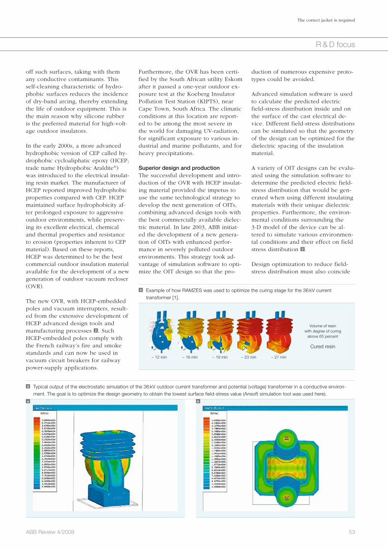
53ABB Review 4/2008
The correct jacket is required
R & D focus
duction of numerous expensive proto-types could be avoided.
Advanced simulation software is used to calculate the predicted electric field-stress distribution inside and on the surface of the cast electrical de-vice. Different field-stress distributions can be simulated so that the geometry of the design can be optimized for the dielectric spacing of the insulation material.
A variety of OIT designs can be evalu-ated using the simulation software to determine the predicted electric field-stress distribution that would be gen-erated when using different insulating materials with their unique dielectric properties. Furthermore, the environ-mental conditions surrounding the 3-D model of the device can be al-tered to simulate various environmen-tal conditions and their effect on field stress distribution 3 . Design optimization to reduce field-stress distribution must also coincide
Furthermore, the OVR has been certi-fied by the South African utility Eskom after it passed a one-year outdoor ex-posure test at the Koeberg Insulator Pollution Test Station (KIPTS), near Cape Town, South Africa. The climatic conditions at this location are report-ed to be among the most severe in the world for damaging UV-radiation, for significant exposure to various in-dustrial and marine pollutants, and for heavy precipitations. Superior design and productionThe successful development and intro-duction of the OVR with HCEP insulat-ing material provided the impetus to use the same technological strategy to develop the next generation of OITs, combining advanced design tools with the best commercially available dielec-tric material. In late 2003, ABB initiat-ed the development of a new genera-tion of OITs with enhanced perfor-mance in severely polluted outdoor environments. This strategy took ad-vantage of simulation software to opti-mize the OIT design so that the pro-
off such surfaces, taking with them any conductive contaminants. This self-cleaning characteristic of hydro-phobic surfaces reduces the incidence of dry-band arcing, thereby extending the life of outdoor equipment. This is the main reason why silicone rubber is the preferred material for high-volt-age outdoor insulators.
In the early 2000s, a more advanced hydrophobic version of CEP called hy-drophobic cycloaliphatic epoxy (HCEP; trade name Hydrophobic Araldite®) was introduced to the electrical insulat-ing resin market. The manufacturer of HCEP reported improved hydrophobic properties compared with CEP. HCEP maintained surface hydrophobicity af-ter prolonged exposure to aggressive outdoor environments, while preserv-ing its excellent electrical, chemical and thermal properties and resistance to erosion (properties inherent to CEP material). Based on these reports, HCEP was determined to be the best commercial outdoor insulation material available for the development of a new generation of outdoor vacuum recloser (OVR).
The new OVR, with HCEP-embedded poles and vacuum interrupters, result-ed from the extensive development of HCEP advanced design tools and manufacturing processes 2 . Such HCEP-embedded poles comply with the French railway’s fire and smoke standards and can now be used in vacuum circuit breakers for railway power-supply applications.
3 Typical output of the electrostatic simulation of the 36 kV outdoor current transformer and potential (voltage) transformer in a conductive environ-ment. The goal is to optimize the design geometry to obtain the lowest surface field-stress value (Ansoft simulation tool was used here).
a b
4 Example of how RAMZES was used to optimize the curing stage for the 36 kV current transformer [1].
Volume of resinwith degree of curing
above 65 percent
Cured resin
~ 12 min ~ 16 min ~ 19 min ~ 23 min ~ 27 min
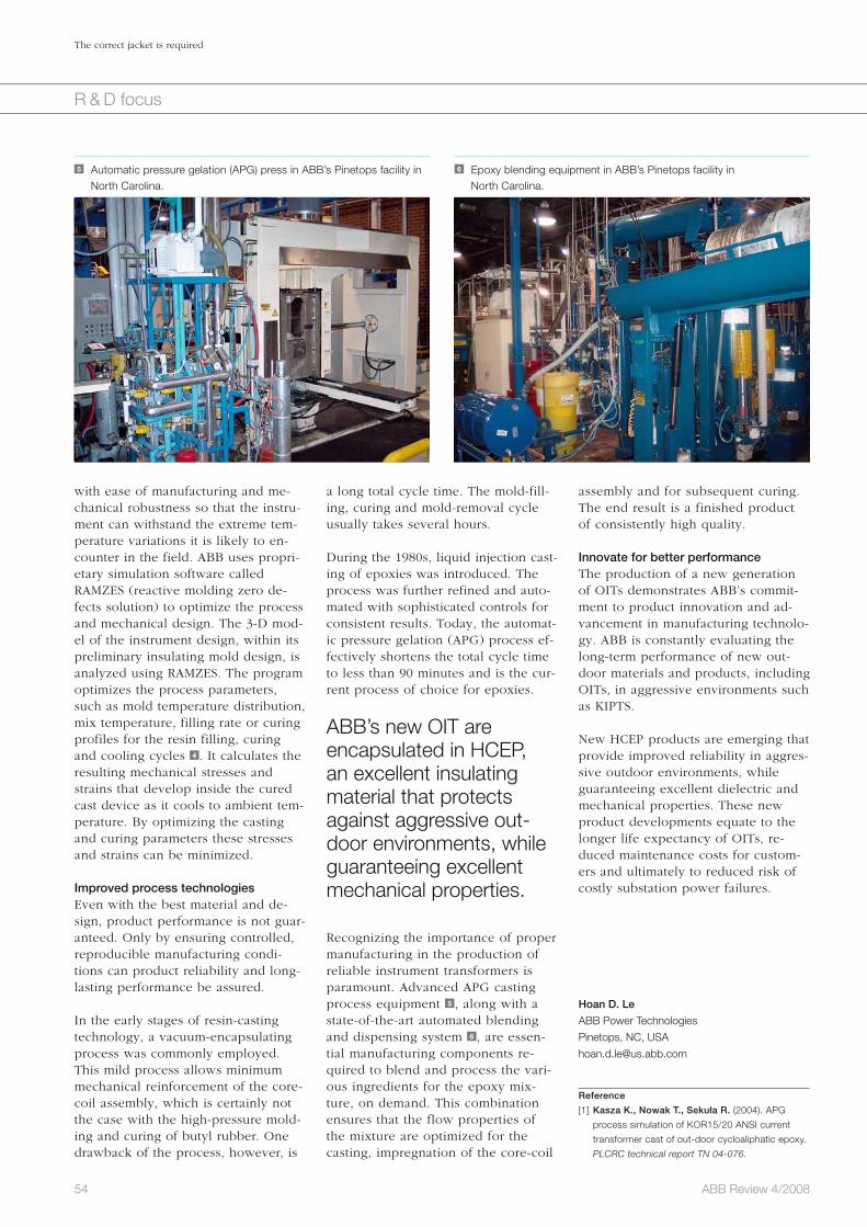
54 ABB Review 4/2008
The correct jacket is required
R & D focus
assembly and for subsequent curing. The end result is a finished product of consistently high quality.
Innovate for better performance The production of a new generation of OITs demonstrates ABB’s commit-ment to product innovation and ad-vancement in manufacturing technolo-gy. ABB is constantly evaluating the long-term performance of new out-door materials and products, including OITs, in aggressive environments such as KIPTS.
New HCEP products are emerging that provide improved reliability in aggres-sive outdoor environments, while guaranteeing excellent dielectric and mechanical properties. These new product developments equate to the longer life expectancy of OITs, re-duced maintenance costs for custom-ers and ultimately to reduced risk of costly substation power failures.
Hoan D. Le
ABB Power Technologies
Pinetops, NC, USA
Reference
[1] Kasza K., Nowak T., Sekuła R. (2004). APG
process simulation of KOR15/20 ANSI current
transformer cast of out-door cycloaliphatic epoxy.
PLCRC technical report TN 04-076.
a long total cycle time. The mold-fill-ing, curing and mold-removal cycle usually takes several hours.
During the 1980s, liquid injection cast-ing of epoxies was introduced. The process was further refined and auto-mated with sophisticated controls for consistent results. Today, the automat-ic pressure gelation (APG) process ef-fectively shortens the total cycle time to less than 90 minutes and is the cur-rent process of choice for epoxies.
ABB’s new OIT are encapsulated in HCEP, an excellent insulating material that protects against aggressive out-door environments, while guaranteeing excellent mechanical properties.
Recognizing the importance of proper manufacturing in the production of reliable instrument transformers is paramount. Advanced APG casting process equipment 5 , along with a state-of-the-art automated blending and dispensing system 6 , are essen-tial manufacturing components re-quired to blend and process the vari-ous ingredients for the epoxy mix-ture, on demand. This combination ensures that the flow properties of the mixture are optimized for the casting, impregnation of the core-coil
with ease of manufacturing and me-chanical robustness so that the instru-ment can withstand the extreme tem-perature variations it is likely to en-counter in the field. ABB uses propri-etary simulation software called RAMZES (reactive molding zero de-fects solution) to optimize the process and mechanical design. The 3-D mod-el of the instrument design, within its preliminary insulating mold design, is analyzed using RAMZES. The program optimizes the process parameters, such as mold temperature distribution, mix temperature, filling rate or curing profiles for the resin filling, curing and cooling cycles 4 . It calculates the resulting mechanical stresses and strains that develop inside the cured cast device as it cools to ambient tem-perature. By optimizing the casting and curing parameters these stresses and strains can be minimized.
Improved process technologiesEven with the best material and de-sign, product performance is not guar-anteed. Only by ensuring controlled, reproducible manufacturing condi-tions can product reliability and long-lasting performance be assured.
In the early stages of resin-casting technology, a vacuum-encapsulating process was commonly employed. This mild process allows minimum mechanical reinforcement of the core-coil assembly, which is certainly not the case with the high-pressure mold-ing and curing of butyl rubber. One drawback of the process, however, is
5 Automatic pressure gelation (APG) press in ABB’s Pinetops facility in North Carolina.
6 Epoxy blending equipment in ABB’s Pinetops facility in North Carolina.

55ABB Review 4/2008
R & D focus
The demands on modern power networks are very different from those for which they were originally designed. Tradi-tional power networks were built around large, centralized power plants, supplying power to the grid in a predictable manner. The one-way flow of power was maintained in these grids, despite hourly fluctuations in demand, thanks to the careful management of each section of the grid.
Today, modern power networks must cope with energy trading, which allows adjacent networks to exchange power, and renewable power sources, which are, by their nature, erratic.
This increased unpredictability in the grid creates an ever-greater demand for high quality surveillance to detect and
Under surveillanceThe world power struggleVladimir Brandwajn, Magnus Johansson, Marina Öhrn
report disturbances in the network. Poor visibility in the power system hampered network operators during the blackouts in Canada, the US and Europe in 2003. These disturbances spread more widely and lasted longer than necessary because operators were sometimes unaware of the scale of the problem.
The economic and social effects of such blackouts clearly demonstrate the need for improved monitoring systems that allow operators to know when and how to act to avoid a system failure. ABB’s Network ManagerTM Supervi-sory Control and Data Acquisition (SCADA)/ Energy Man-agement System (EMS) are tried and tested technologies that can help manage the changing demands of today’s power networks.
SCADA and EMS are the primary building blocks for a modern pow-
er grid control system 1 . SCADA con-sists of measuring devices, communi-cations and control systems, while EMS comprises various power system analysis functions. By working hand in hand, SCADA and EMS can create a highly visible transmission system for power system operators, allowing them to collect, store and analyze data from hundreds of thousands of data points in national or regional net-works, to perform network modeling, simulate power operation, pinpoint faults, pre-empt blackouts and partici-pate in energy trading markets.
EMS comprises of a series of processes that must be performed in a pre-de-fined sequence. An example of the real-time sequence is shown schemati-cally in 2 . For transmission operators, the two most important components of this scheme are the state estimator (SE) and the contingency analysis (CA).
The SE provides information about the state of the power system at any given
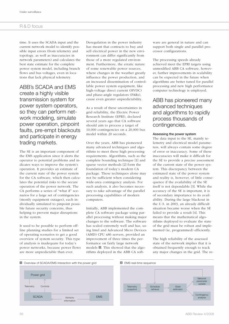
ware are general in nature and can support both single and parallel pro-cessor configurations.
The processing speeds already achieved meet the EPRI targets using unmodified ABB CA software, howev-er, further improvements in scalability can be expected in the future when algorithms are better tuned for parallel processing and new high performance computer technology is employed.
ABB has pioneered many advanced techniques and algorithms to rapidly process thousands of contingencies.
Assessing the power systemThe data input to the SE, mainly te-lemetry and electrical model parame-ters, will always contain some degree of error or inaccuracy. Some of these inaccuracies will make it difficult for the SE to provide a precise assessment of the current state of the power sys-tem. This discrepancy between the estimated state of the power system and reality is, however, of little conse-quence if the availability of the SE itself is not dependable [3]. While the accuracy of the SE is important, it is of secondary importance to its avail-ability. During the large blackout in the U.S. in 2003, an already difficult situation became worse when the SE failed to provide a result [4]. This means that the mathematical algo-rithms deployed to evaluate the state of the grid must be robust and imple-mented (ie, programmed) efficiently.
The high reliability of the assessed state of the network implies that it is obtained frequently enough to track any major changes in the grid. The re-
Deregulation in the power industry has meant that contracts to buy and sell electrical power in the new envi-ronment can differ significantly from those of a more regulated environ-ment. Furthermore, the erratic nature of some renewable power sources, where changes in the weather greatly influence the power production, and an increased dissemination of control-lable power system equipment, like high-voltage direct current (HVDC) and phase-angle regulators (PARs), cause even greater unpredictability.
As a result of these uncertainties in grid reliability, the Electric Power Research Institute (EPRI), declared several years ago that CA software should aim to process a target of 10,000 contingencies on a 20,000 bus model within 20 seconds.
Over the years, ABB has pioneered many advanced techniques and algo-rithms to meet these high processing requirements. Algorithms, such as the complete bounding technique [1] and sparse vector methods [2] form the foundation of today’s modern CA package. These techniques alone may not be sufficient when considering wide-area contingency analysis. For such analysis, it also becomes neces-sary to take advantage of the parallel processing capabilities of modern computers.
Initially, ABB implemented the com-plete CA software package using par-allel processing without making major changes to the software. The software has scaled extremely well and has, us-ing Intel and Advanced Micro Devices (AMD) CPU x86 servers, provided an improvement of three times the per-formance on fairly large network models 3 . This showed that the algo-rithms deployed in the ABB CA soft-
56 ABB Review 4/2008
Under surveillance
R & D focus
1 Overview of SCADA/EMS interaction with the power grid
Power grid
SCADA EMS
Telemetry Controls
Advisoryinformation
2 EMS real-time sequence
Telemetrysnapshot
Scheduleretrieval
State estimator
Networkparameter
update
Contingencyanalysis
time. It uses the SCADA input and the current network model to identify pos-sible input errors (from telemetry and topology, as well as inaccuracies in network parameters) and calculates the best state estimate for the complete power system model, including branch flows and bus voltages, even in loca-tions that lack physical telemetry.
ABB’s SCADA and EMS create a highly visible transmission system for power system operators, so they can perform net-work modeling, simulate power operation, pinpoint faults, pre-empt blackouts and participate in energy trading markets.
The SE is an important component of the EMS application since it alerts the operator to potential problems and in-dicates ways to improve the system’s operation. It provides an estimate of the current state of the power system for the CA software, which then calcu-lates the potential risks to the secure operation of the power network. The CA performs a series of “what if” sce-narios for a large set of contingencies (mostly equipment outages), each in-dividually simulated to pinpoint possi-ble future security concerns, thus helping to prevent major disruptions in the system.
It used to be possible to perform off-line planning studies for a limited set of operating scenarios to get a good overview of system security. This type of analysis is inadequate for today’s power networks, because power flows are more unpredictable than ever.

57ABB Review 4/2008
Under surveillance
R & D focus
and power exchange schedule) exactly
2. 100 percent of the market was to be dispatched (re-scheduled) every 5 minutes
3. Erroneous SE results needed to be identified before they were trans-mitted to market applications – the primary objective being security of the power grid
demands on the functionality of the CA, including the ability to accurately process approximately 3,000 “what if” scenarios, every minute, on computers purchased in 1999.
There were four main IESO require-ments for the SE.1. SCADA/EMS was expected to moni-
tor market dispatch (generation
liability of this SE software is not only a function of the SE software and te-lemetry from SCADA, but also of the supporting software, like the network parameter update (NPU) that is used to maintain set patterns necessary to generate data, eg, load or generation patterns. The SE solution is used as an input to NPU and the NPU output is in turn, used as an input to SE for locations lacking adequate physical telemetry. It is, therefore, unwise, to consider these as separate and inde-pendent functions because they form a single interdependent system.
The reliability of the entire system is dependent on its components and their ability to work together. This, to-gether with customized operator inter-faces, is extremely important if high-level surveillance of the transmission grid is to be maintained so that opera-tors can make appropriate, timely de-cisions to prevent a network failure.
Meeting customer’s needsSeveral years ago, ABB received a large order for a complete SCADA/EMS and market applications system for the independent electricity system operator (IESO) in Ontario, Canada Factbox 1 .
The IESO had very high reliability re-quirements in view of the fact that the results of the SE were going to sup-port not only the EMS applications, but also the market operations sys-tems that involve financial transac-tions [5]. There were also very high
3 Initial parallel scalability of the contingency analysis
1.2
1.0
0.8
0.6
0.4
0.2
0
Number of CPUs
1 2 3 4
Application scalability
4 Recent SE solution reliability (data supplied by the IESO)
12 month availability
June 2007 – May 2008
Monthly availability
Average
100.0
99.8
99.6
99.4
99.2
99.0
98.8
98.6
98.4
98.2
98
Nor
mal
ized
exe
cutio
n tim
e
Rel
iabi
lity
(per
cent
)
Factbox 1 IESO transmission system characteristics
Ontario's internal zones, internal interfaces and external interconnections
Northwestzone
Westzone
Niagarazone
Northeastzone
Essazone
Ottawazone
Eastzone
Manitobainterconnection(PAR controlled)
Minnesotainterconnection(PAR controlled)
Michiganinterconnection(PAR controlled)
New Yorkinterconnection(free flowing)
New Yorkinterconnection(PAR controlled)
Quebecinterconnection(Radial)
Quebecinterconnection(Radial)
Quebecinterconnection(Radial)
Quebecinterconnection(HVDC)
EWTE
TEC
EWTW
Torontozone
Brucezone
FETT
Southwestzone
The IESO network model has a size of roughly 4,000 buses and a peak load of around 25,000 MW. The IESO’s transmission system is divided into 10 different zones with different characteristics with respect to the availability of telemetry, level of stress, generation mix and external interfaces. There are external connections that use PARs to control the tie-line flows so as to avoid exceeding thermal limits.

58 ABB Review 4/2008
Under surveillance
R & D focus
With the introduction of ABB’s upgrad-ed surveillance system based on the improved EMS, the operators of the Ontario power grid are confident that they have taken an important step to minimize the risk of future blackouts.
Vladimir Brandwajn
ABB Network Management
Santa Clara, CA, USA
Magnus Johansson
ABB Network Management
Västerås, Sweden
Marina Öhrn
ABB Network Management
Mannheim, Germany
SE improved over time as a direct result of these cooperative efforts.
ABB has deployed its expertise in the area of network solutions, as well as research and development, often directly resulting from joint IESO-ABB analysis, identifying the source of in-accuracies or reasons for non-conver-gence. The recent significant increase in SE availability can be directly attrib-uted to the latest NPU and SE soft-ware enhancements [6].
It should be pointed out that the SE availability numbers achieved on the IESO system are much higher than those in other systems Factbox 2 . The SE analysis is performed every minute as part of the real-time sequence 2 . Therefore, a shift in the reliability from 99.7 to 99.8 percent has reduced the number of unavailable SE solutions by more than 40 each month.
The SCED identifies the least expensive generat-ing and demand manage-ment resources required to meet the power needs of the region, while con-sidering the overall securi-ty of the transmission system.
The iterative SE solution provides very high accuracy, which is required to support the CA as well as market ap-plications. This is achieved through the Business Management Systems (BMS) network-security-constrained economic dispatch (SCED). The SCED identifies the least expensive generat-ing and demand management resourc-es required to meet the power needs of the region, while considering the overall security of the transmission system. The interaction between the EMS and BMS (market applications) is shown schematically 5 . The SCADA/EMS sends the current state of the power system to the BMS market ap-plications, which then perform the economic dispatch based on predic-tions, five minutes into the future and returns new generation base points to the SCADA/EMS.
4. Initial conditions (base case) were needed for real-time system security monitoring and contingency analysis
ABB’s CA softwareis general in nature and can support both single and parallel processorconfigurations.
To meet the customer’s requirements, ABB has significantly enhanced its EMS product. Improvements were made to the availability and quality of the SE solution, together with the speed and accuracy of CA and all supporting functions.
During the implementation of the project, ABB worked closely with the customer, discussing and evaluating their needs and delivering the best possible solutions. This required the IESO to improve the quality of the power system data and ABB to en-hance the software so that a highly reliable grid surveillance system could be achieved 4 . The availability of the
Factbox 2 SE reliability requirements
According to [7], “the average reliability of
the state estimator in the US industry is
95 percent.” In [8], more specific numbers
are provided by a North American utility:
93.2 percent in 2001
97.3 percent in 2005
The SE reliability requirements for the
Midwest Independent Systems Operator
(MISO) have been set to 97 percent. The
same level is also favored by the Electric
Reliability Council of Texas (ERCOT).
References
[1] Brandwajn, V., Lauby, M. G. (1989). Complete
bounding method for AC contingency screening.
IEEE Trans. Power Syst., 4(2), 724–729.
[2] Tinney, W. F., Brandwajn, V., Chan, S. M. (1985).
Sparse vector methods. IEEE Trans. Power App.
Syst., PAS-104(2), 295–301.
[3] Wollenberg, B. (2004). Power system state esti-
mators: Designed for reliability or accuracy? 8th
International conference on probabilistic methods
applied to power systems.
[4] http://www.iwar.org.uk/cip/resources/blackout-03/
index.htm (April 2004). Chapter 4 of Final report on
the August 14, 2003 blackout in the United States
and Canada: Causes and recommendations.
US-Canada power system outage task force.
[5] Danai, B., Kim, J., Cohen, A. I., Brandwajn, V.,
Chang, S. K. (2001). Scheduling energy and an-
cillary service in the new Ontario electricity mar-
ket. Proc. Institute of Electrical and Electronics
Engineers Power Industry Computer Application
Conference.
[6] Brandwajn, V., Jiang, X., Liu, G., Johansson,
M. L., Fahmy, G.G. (2006). State Estimation for
Ontario Market System. IEEE PES General Meet-
ing
[7] http://www.oe.energy.gov/DocumentsandMedia/
Distribution_State_Estimation_Meliopoulos.pdf
(June, 2008) Distributed state estimation. Georgia
Institute of Technology.
[8] Lefebvre, S., Prévost, J., Crainic, E., St-Arnaud,
R., Horisberger, H., Lambert, B. (2006). Practical
experience with state estimation. RTE Workshop
on robust state estimation and load forecasting.
5 SCADA/EMS – BMS interaction (AGC – Automatic Generation Control).
SCADA/EMS
Marketapplications
AGC basepoints
SE solutions
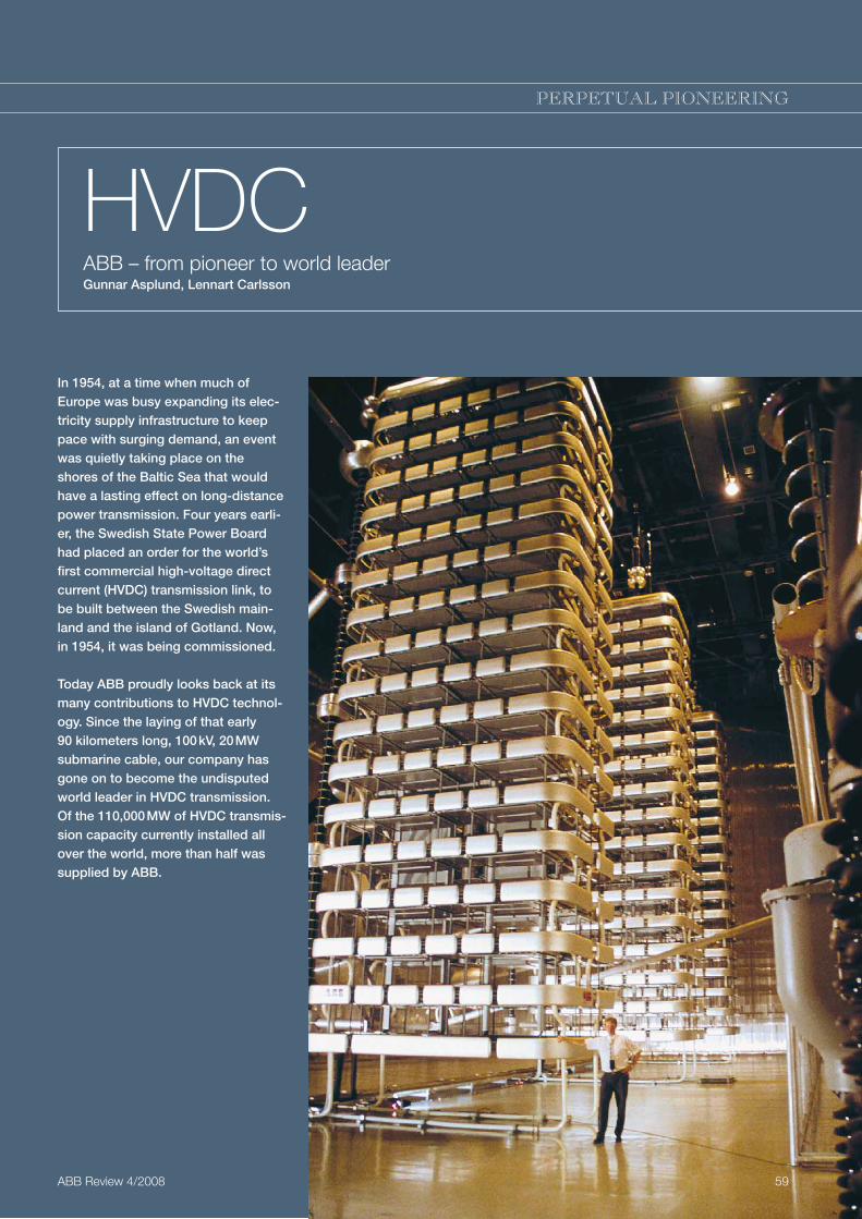
Thema
HVDCABB – from pioneer to world leaderGunnar Asplund, Lennart Carlsson
PERPETUAL PIONEERING
In 1954, at a time when much of Europe was busy expanding its elec-tricity supply infrastructure to keep pace with surging demand, an event was quietly taking place on the shores of the Baltic Sea that would have a lasting effect on long-distance power transmission. Four years earli-er, the Swedish State Power Board had placed an order for the world’s first commercial high-voltage direct current (HVDC) transmission link, to be built between the Swedish main-land and the island of Gotland. Now, in 1954, it was being commissioned.
Today ABB proudly looks back at its many contributions to HVDC technol-ogy. Since the laying of that early 90 kilometers long, 100 kV, 20 MW submarine cable, our company has gone on to become the undisputed world leader in HVDC transmission. Of the 110,000 MW of HVDC transmis-sion capacity currently installed all over the world, more than half was supplied by ABB.
ABB Review 4/2008 59

1000 V, the possibility of developing valves for even higher voltages had been continually investigated.
This necessitated the study of new fields in which only a limited amount of existent technical experience could be applied. In fact, for some years it was debated whether it would be possible at all to find solutions to all the vari-ous problems. When HVDC transmission finally proved to be technically feasible there still remained uncertainty as to whether it could success-fully compete with HVAC in the marketplace.
Whereas rotating electrical machines and transformers can be designed very precisely with the aid of mathe-matically formulated physical laws, mercury-arc valve design depends to a large degree on knowledge acquired empirically. As a result, attempts to increase the voltage in the mercury-vapor-filled tube by enlarging the gap between the anode and cathode invariably failed.
The problem was solved in 1929 by a proposal to insert grading electrodes between the anode and cathode. Sub-sequently patented, this innovative solution can in some ways be consid-ered as the cornerstone of all later development work on the high-volt-age mercury-arc valve. It was during this time that Dr. Uno Lamm, who led the work, earned his reputation as the “father” of HVDC’.
The Gotland linkThe time was now ripe for service trials at higher powers. Together with the Swedish State Power Board, the company set up, in 1945, a test station at Trollhättan, where there was a major power plant that could provide energy. A 50 km power line was also made available.
Trials carried out over the following years led to the Swedish State Power Board placing, in 1950, an order for equipment for the world’s first HVDC transmission link. This was to be built between the island of Gotland
lived and worked, long overhead lines were built, over which AC at ever-higher voltages flowed. To bridge expanses of water, submarine cable was developed.
Neither of these transmission media was without its problems, however. Specifically, they were caused by the reactive power that oscillates between the capacitances and inductances in the systems. As a result, power system planners began once again to look at the possibility of transmitting direct current.
Even when HVDC trans-mission finally proved technically feasible, it was doubted for a long time whether it could compete with HVAC in the market-place.
Back to DCWhat had held up high-voltage direct current transmission in the past was, first and foremost, the lack of reliable and economic valves that could con-vert HVAC into HVDC, and vice versa.
The mercury-arc valve offered, for a long time, the most promising line of development. Ever since the end of the 1920s, when the Swedish ASEA – a founding company of ABB – began making static converters and mercury-arc valves for voltages up to about
With the arrival of the electric light bulb in
the homes and factories of late 19th century Europe and the USA, demand for electric-ity grew rapidly and engi-neers and entrepreneurs alike were soon busily searching for efficient ways to generate and transmit it. The pioneers of this new technology had already made some progress – just being able to transmit power a few kilometers was regarded as something fan-tastic – when an answer to growing demand was found: hydroelectric power. Almost immediately, interest turned to finding ways of transmit-ting this cheap electricity to consum-ers over longer distances.
First direct, then alternating currentThe first power stations in Europe and the USA supplied low-voltage, direct current (DC) electricity, but the trans-mission systems they used were inef-ficient. This was because much of the generated power was lost in the cables. Alternating current (AC) of-fered much better efficiency, since it could easily be transformed to higher voltages, with far less loss of power. The stage was thus set for long-dis-tance high-voltage AC (HVAC) trans-mission.
In 1893, HVAC got another boost with the introduction of three-phase trans-mission. Now it was possible to en-sure a smooth, non-pulsating flow of power.
Although direct current had been beaten at the starting gate in the race to develop an efficient transmission system, engineers had never com-pletely given up the idea of using DC. Attempts were still being made to build a high-voltage transmission sys-tem with series-connected DC genera-tors and, at the receiving end, series-connected DC motors – all on the same shaft. This worked, but it was not commercially successful.
AC dominatesAs the AC systems grew and power increasingly was being generated far from where most of its consumers
60 ABB Review 4/2008
Analog simulator used in the design of the early HVDC transmission systems
PERPETUAL PIONEERINGPERPETUAL PIONEERING
HVDC
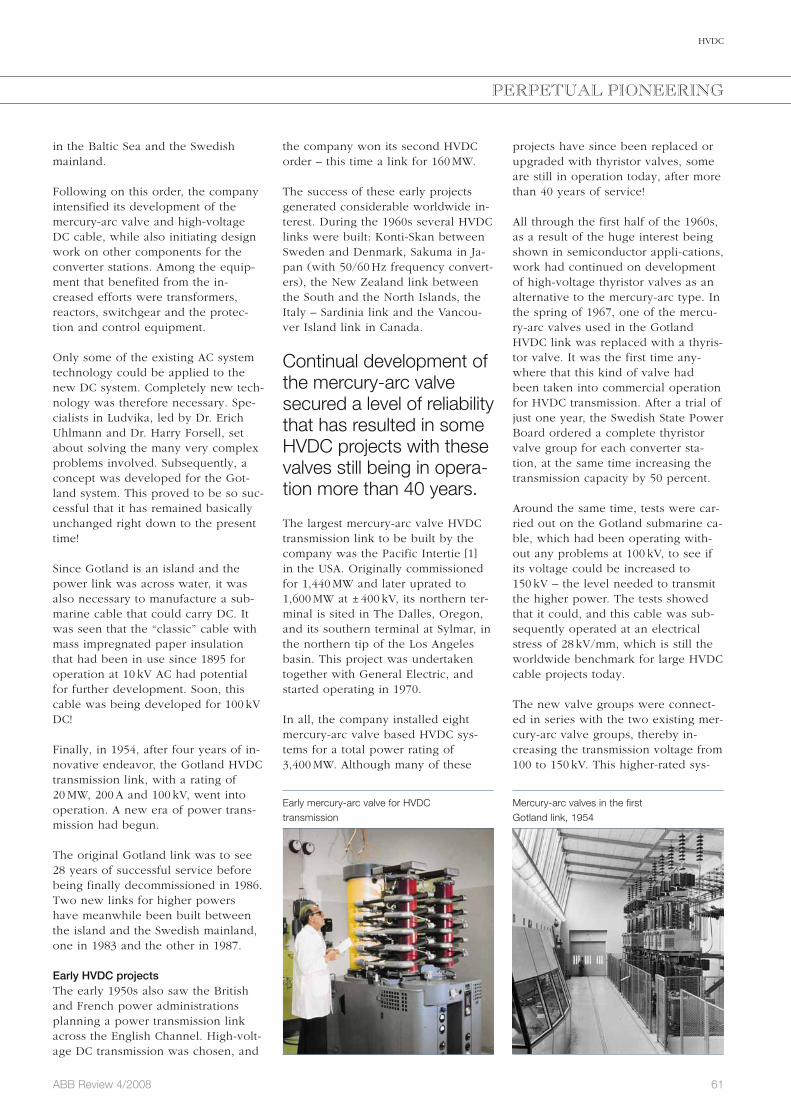
61ABB Review 4/2008
HVDC
PERPETUAL PIONEERING
projects have since been replaced or upgraded with thyristor valves, some are still in operation today, after more than 40 years of service!
All through the first half of the 1960s, as a result of the huge interest being shown in semiconductor appli-cations, work had continued on development of high-voltage thyristor valves as an alternative to the mercury-arc type. In the spring of 1967, one of the mercu-ry-arc valves used in the Gotland HVDC link was replaced with a thyris-tor valve. It was the first time any-where that this kind of valve had been taken into commercial operation for HVDC transmission. After a trial of just one year, the Swedish State Power Board ordered a complete thyristor valve group for each converter sta-tion, at the same time increasing the transmission capacity by 50 percent.
Around the same time, tests were car-ried out on the Gotland submarine ca-ble, which had been operating with-out any problems at 100 kV, to see if its voltage could be increased to 150 kV – the level needed to transmit the higher power. The tests showed that it could, and this cable was sub-sequently operated at an electrical stress of 28 kV/mm, which is still the worldwide benchmark for large HVDC cable projects today.
The new valve groups were connect-ed in series with the two existing mer-cury-arc valve groups, thereby in-creasing the transmission voltage from 100 to 150 kV. This higher-rated sys-
the company won its second HVDC order – this time a link for 160 MW.
The success of these early projects generated considerable worldwide in-terest. During the 1960s several HVDC links were built: Konti-Skan between Sweden and Denmark, Sakuma in Ja-pan (with 50/60 Hz frequency convert-ers), the New Zealand link between the South and the North Islands, the Italy – Sardinia link and the Vancou-ver Island link in Canada.
Continual development of the mercury-arc valve secured a level of reliability that has resulted in some HVDC projects with these valves still being in opera-tion more than 40 years.
The largest mercury-arc valve HVDC transmission link to be built by the company was the Pacific Intertie [1] in the USA. Originally commissioned for 1,440 MW and later uprated to 1,600 MW at ± 400 kV, its northern ter-minal is sited in The Dalles, Oregon, and its southern terminal at Sylmar, in the northern tip of the Los Angeles basin. This project was undertaken together with General Electric, and started operating in 1970.
In all, the company installed eight mercury-arc valve based HVDC sys-tems for a total power rating of 3,400 MW. Although many of these
in the Baltic Sea and the Swedish mainland.
Following on this order, the company intensified its development of the mercury-arc valve and high-voltage DC cable, while also initiating design work on other components for the converter stations. Among the equip-ment that benefited from the in-creased efforts were transformers, reactors, switchgear and the protec-tion and control equipment.
Only some of the existing AC system technology could be applied to the new DC system. Completely new tech-nology was therefore necessary. Spe-cialists in Ludvika, led by Dr. Erich Uhlmann and Dr. Harry Forsell, set about solving the many very complex problems involved. Subsequently, a concept was developed for the Got-land system. This proved to be so suc-cessful that it has remained basically unchanged right down to the present time!
Since Gotland is an island and the power link was across water, it was also necessary to manufacture a sub-marine cable that could carry DC. It was seen that the “classic” cable with mass impregnated paper insulation that had been in use since 1895 for operation at 10 kV AC had potential for further development. Soon, this cable was being developed for 100 kV DC!
Finally, in 1954, after four years of in-novative endeavor, the Gotland HVDC transmission link, with a rating of 20 MW, 200 A and 100 kV, went into operation. A new era of power trans-mission had begun.
The original Gotland link was to see 28 years of successful service before being finally decommissioned in 1986. Two new links for higher powers have meanwhile been built between the island and the Swedish mainland, one in 1983 and the other in 1987.
Early HVDC projectsThe early 1950s also saw the British and French power administrations planning a power transmission link across the English Channel. High-volt-age DC transmission was chosen, and
Early mercury-arc valve for HVDC transmission
Mercury-arc valves in the first Gotland link, 1954

62 ABB Review 4/2008
HVDC
HVDC todayThe majority of HVDC converter sta-tions built today are still based on the principles that made the original Got-land link such a success back in 1954. Station design underwent its first big change with the introduction of thyris-tor valves in the early 1970s. The first of these were air-cooled and designed for indoor use, but soon outdoor oil-cooled, oil-insulated valves were also being used. Today, all HVDC valves are water-cooled [2].
Good examples of modern bulk pow-er HVDC transmission are the links ABB is installing for the Three Gorges hydroelectric power plant project in China.
In 1995 ABB presented a new genera-tion of HVDC converter stations: HVDC 2000 [3]. HVDC 2000 was developed to meet stricter electrical disturbance requirements, to provide better dynamic stability where there was insufficient short-circuit capacity, to overcome space limitations, and to shorten delivery times.
A key feature of HVDC 2000 was the introduction of capacitor commutated converters (CCC). This was, in fact, the first fundamental change to have been made to the basic HVDC system technology since 1954!
HVDC 2000 also includes other ABB innovations, such as continuously tuned AC filters (ConTune), active DC filters, outdoor air-insulated HVDC valves, and the fully digital MACH2™ control system.
role in the Brazilian power scheme, supplying a large portion of the elec-tricity for the city of São Paulo.
The scale and technical complexity of the Itaipu project presented a consid-erable challenge, and it can be con-sidered as the start of the modern HVDC era. The experience gained in the course of its completion has been in no small way responsible for the many HVDC orders awarded to ABB in the years since.
The scale and complexity of the Itaipu project pre-sented a considerable challenge, and it can be considered as the start of the modern HVDC era.
The most challenging HVDC project in the late 1980s and in the early 1990s was undoubtedly the 2,000 MW Qué-bec – New England link. This was the first large multi-terminal HVDC trans-mission system to be built anywhere in the world.
HVDC cables have kept paceAs the converter station ratings in-creased, so too did the powers and voltage levels for which the HVDC cables had to be built.
The most powerful HVDC submarine cables to date are rated 700 to 800 MW at 450 to 500 kV. The longest of these are the the 580 km NorNed link be-tween Norway and The Netherlands taken in service in 2008.
tem was taken into service in the spring of 1970 – another world’s “first” for the Gotland transmission link.
With the advent of thyristor valves it became possible to simplify the con-verter stations, and semiconductors have been used in all subsequent HVDC links. Other companies were now entering the field. Brown Boveri (BBC) – which later merged with ASEA to form ABB – teamed up with Siemens and AEG in the mid-1970s to build the 1,920 MW Cahora Bassa HVDC link between Mozambique and South Africa. The same group then went on to build the 2,000 MW Nelson River 2 link in Canada. This was the first project to employ water-cooled HVDC valves.
The late 1970s also saw the comple-tion of new projects. These were the Skagerrak link between Norway and Denmark, Inga-Shaba in the Congo, and the CU Project in the USA.
The Pacific Intertie was also extended twice in the 1980s, each time with thyristor converters, to raise its capac-ity to 3,100 MW at ± 500 kV. The Syl-mar terminal is since 2004 equipped with thyristor converters for the full power capacity.
Itaipu – the new benchmark The contract for the largest of all HVDC transmission schemes in the 20th century, the 6,300 MW Itaipu HVDC link in Brazil, was awarded to the ASEA-PROMON consortium in 1979. This project was completed and put into operation in several stages between 1984 and 1987. It plays a key
Foz do Iguaçu converter station with the Itaipu 12,600 MW power stationin the background
Baltic Cable HVDC converter station
PERPETUAL PIONEERING

63ABB Review 4/2008
HVDC
PERPETUAL PIONEERING
making series connection possible. However, for HVDC a large number of IGBTs have to be connected in series, something industrial drives do not need.
In 1994, ABB concentrated its devel-opment work on VSC converters in a project that aimed at putting two con-verters based on IGBTs into operation for small-scale HVDC. An existing 10-km-long AC line in central Sweden was made available for the project.
At the end of 1996, after comprehen-sive synthetic tests, the equipment was installed in the field for testing under service conditions. In 1997 the world’s first VSC HVDC transmission system, HVDC Light® [4], began trans-mitting power between Hellsjön and Grängesberg in Sweden.
In the meantime, eleven such systems have been ordered, and eight of them are now in commercial operation around the world.
longest power transmission link in China: Xiangjiaba – Shanghai ± 800 kV UHVDC transmission project, rated 6,400 MW. This 2,071 km long trans-mission will be commissioned in 2010 to 2011.
HVDC Light®
HVDC technology has become a ma-ture technology over the past 50 years and reliably transmits power over long distances with very low losses. This begs the question: where is development work likely to go in the future?
It was conceived that HVDC develop-ment could, once again, take its cue from industrial drives. Here, thyristors were replaced a long time ago by voltage source converters (VSC), with semiconductors that can be switched off as well as on. These have brought many advantages to the control of industrial drive systems and it was realized that they could also apply to transmission systems. Adapting the technology of voltage source convert-ers to HVDC, however, is no easy matter. The entire technology has to change, not just the valves.
As development of its VSC converter got under way, ABB realized that the insulated gate bipolar transistor, or IGBT, held more promise than all the other available semiconductor compo-nents. Above all else, the IGBT needs only very little power for its control,
The first project to employ HVDC 2000 with CCC and outdoor valves was the Garabi 2,200 MW HVDC back-to-back station in the Brazil – Argenti-na HVDC Interconnection. The Apollo converter station (South Africa) in the Cahora Bassa transmission was equipped with new outdoor air-insu-lated HVDC valves in 2008.
The most powerful HVDC submarine cables to date are rated 700 to 800 MW at 450 to 500 kV.
UHVDCUntil now, the majority of the largest HVDC transmissions rated 2,000 MW or more have been designed for volt-ages in the ± 500 to 600 kV range. But these levels were not sufficient for the transmissions of around 2,000 km from the giant hydro power stations now being in built China and India. Be-tween 5,000 and 8,000 MW has to be sent over a single bipole in these transmissions. Ultra High Voltage DC (UHVDC) of ± 800 kV proved to be the optimal choice considering invest-ments, losses and technical limita-tions. This called for major develop-ments for the converter station equip-ment. ABB has developed equipment for the new DC voltage level and has performed long term tests on them. ABB is currently delivering ultrahigh-voltage technology for the world’s
Submarine cable for the 600 MW BalticCable HVDC link between Germany and Sweden
HVDC Light land cable
Laying the cable for the Gotland HVDC link in 1954
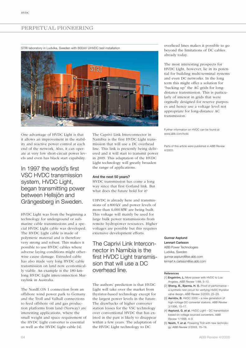
64 ABB Review 4/2008
HVDC
The Caprivi Link Interconnector in Namibia is the first HVDC Light trans-mission that will use a DC overhead line. This link is presently being deliv-ered and it will start to transmit power in 2009. This adaptation of the HVDC Light technology will greatly broaden the range of applications.
And the next 50 years?HVDC transmission has come a long way since that first Gotland link. But what does the future hold for it?
UHVDC is already here and transmis-sions of ± 800 kV and power levels of more than 6,000 MW are being built. This voltage will mainly be used for large bulk power transmissions from remote hydropower resources. Higher voltages are possible but this requires extensive development efforts.
The Caprivi Link Intercon-nector in Namibia is the first HVDC Light transmis-sion that will use a DC overhead line.
The authors’ prediction is that HVDC Light will take over the market from thyristor-based technology except for the largest power levels in the future. The drawbacks of higher converter station losses for the VSC technology over conventional HVDC that has ex-isted in the past is likely to disappear within a few years. The adaptation of the HVDC Light technology to DC
One advantage of HVDC Light is that it allows an improvement in the stabil-ity and reactive power control at each end of the network. Also, it can oper-ate at very low short-circuit power lev-els and even has black start capability.
In 1997 the world’s first VSC HVDC transmission system, HVDC Light, began transmitting power between Hellsjön and Grängesberg in Sweden.
HVDC Light was from the beginning a technology for underground or sub-marine cable transmissions and a spe-cial HVDC Light cable was developed. The HVDC Light cable is made of polymeric material and is therefore very strong and robust. This makes it possible to use HVDC cables where adverse laying conditions might other-wise cause damage. Extruded cable has also made very long HVDC cable transmission on land now economical-ly viable. An example is the 180-km-long HVDC Light interconnection Mur-raylink in Australia.
The NordE.ON 1 connection from an offshore wind power park to Gemany and the Troll and Valhall connections to feed offshore oil and gas produc-tion platforms from land (Norway) are interesting applications, where the small weight and space requirement of the HVDC Light converter is essential as well as the HVDC Light cable [4].
STRI laboratory in Ludvika, Sweden with 800 kV UHVDC test installation
PERPETUAL PIONEERING
overhead lines makes it possible to go beyond the limitations of DC cables already today.
The most interesting prospects for HVDC Light, however, lie in its poten-tial for building multi-terminal systems and even DC networks. In the long term this might offer a solution for “backing up” the AC grids for long-distance transmission. This is particu-larly of interest in grids that were orginally designed for reserve purpos-es and hence use a voltage level not appropriate for long-distance AC transmission.
Further information on HVDC can be found at
www.abb.com/hvdc
Parts of this article were published in ABB Review
4/2003.
Gunnar Asplund
Lennart Carlsson
ABB Power Technologies
Ludvika, Sweden
References
[1] Engström, L. More power with HVDC to Los
Angeles. ABB Review 1/88, 3–10.
[2] Sheng, B., Bjarma, H. O. Proof of performance –
a synthetic test circuit for verifying HVDC thyristor
valve design. ABB Review 3/2003, 25–29.
[3] Aernlöv, B. HVDC 2000 – a new generation of
high-voltage DC converter stations. ABB Review
3/1996, 10–17.
[4] Asplund, G. et al. HVDC Light – DC transmission
based on voltage sourced converters. ABB
Review 1/1998, 4–9.
[5] Nestli, T. et al. Powering Troll with new technolo-
gy. ABB Review 2/2003, 15–19.

65ABB Review 4/2008
Index
ABB Review 1/2008 Behind the plug
Plugging in Taking a trip behind the electrical outlet 6
Electrical energy The challenge of the next decades 8
Intelligent energy efficiency How KNX bus systems control our buildings 14
A matter of timing An active protection device that reacts quickly to internalarcing enhances operator safety and equipment availability 18
Surviving a short-circuit Short-circuit withstand capability of power transformers 24
Transformer challenges Condition monitoring is becoming a strategic tool for utilities 29
Substation evolution Substation design in the 1900s and modern substations today 34
At the pulse of power ABB is never short of solutions for operating and controlling the grid 39
When grids get smart Intelligent automation for distribution networks 44
Transport or transmit? Should we transport primary energy resources or transmit them as electricity? 48
Powering platforms Connecting oil and gas platforms to mainland power grids 52
Starting the boiler Startup optimization for steam boilers in E.ON power plants 57
To the last drop How wireless communication supports the lifetime extension of oil and gas production 63
“Lady of Victories” This self-contained power generation barge is right at home in the Caspian sea 67
Strictly no admittance Keeping an eye on IT security in the plant 71
A secure future ABB’s Remote Monitoring and Operation Services are changing the way process automation systems are controlled 76
125 years running From the very beginning, ABB has been a pioneer in electrical motors and machines 81
… for a better world
2 / 2008
The corporate technical journal of the ABB Group
www.abb.com/abbreview
ABBReview
a
Tackling water shortages page 19
Weather forecasting page 39
Electrical transmission of the future page 52
1 / 2008
The corporate technical journal of the ABB Group
www.abb.com/abbreview
ABBReview
Pioneering spirits
A revolution in high dc current measurement
page 6
Team-mates: MultiMove functionality heralds a new era in robot applications
page 26
Best innovations 2004page 43
a
Behind the plug
KNX: intelligent bus systems for buildings page 14
Moving energy: transport or transmit? page 48
Motors: 125 years running page 81
ABB Review 2/2008 . . . for a better world
Better technology for a better world Electricity makes life more comfortable – all around the globe 6
Value-added comfort Intelligent electrical installation technology makes living safer, life easier and the use of energy more efficient 10
Invisible safety Electrical installations in buildings 15
Breathing new life Water supply technology is used to tackle the critical global problem of decreasing fresh water supplies 19
Performance on track Electric power products on trains – designed by ABB to make journeys more comfortable 25
Going up! Elevator manufacturer reaches new heights with ABB’s high performance machinery drive 30
Smooth operator Cranes with brains make life comfortable for one and all 34
Watching the weather Better weather forecasting for more safety and comfort 39
Moving more than goalposts ABB drives open and close the giant panels of a stadium roof – and motor starters move the playing field 43
The sound of silence Designing and producing silent transformers 47
Light, safe and effective HVDC Light® cable systems are the future of power transmission 52
Success story Looking back at ABB’s contribution to industrial robotics 56

66 ABB Review 4/2008
Index
ABB Review 3/2008 Power electronics
Conducting business ABB’s power semiconductor business in Lenzburg is making its mark on the energy industry 6
Performance-enhancing packaging Designing an IGBT module packaging for high-quality and reliable operation 9
A tiny dot can change the world High-Power Technology for IGCTs 15
Switching to higher performance The evolution of IGBT technology 19
The workhorse and its jockey Combined with electric motors of any power rating, ABB’s AC drives are winning the race in terms of energy efficiency and process control 25
A team of drives Multidrives with active front-end technology in the cement and minerals industry 30
The compact controller PP D104: A low-end extension to the AC 800PEC Control Platform 35
AC excitation with ANPC ANPC converter technology tailored to the needs of AC excitation equipment for pump storage plants 40
Clean and invisible New transmission technologies are a valuable link to a clean and sustainable future 44
The railway connection Frequency converters for railway power supply 49
Offshore but online PCS6000 wind converter for 5 MW offshore wind turbines 56
Enabling the power of wind HVDC Light® for large-scale offshore wind integration 62
Expedited problem solving A new software diagnostics tool is keeping plant control systems on track 67
Safe landing with pulsed power ABB semiconductor switches are improving radar control systems at US airports 70
The winning chips History of power semiconductors at ABB 72
3 / 2008
The corporate technical journal of the ABB Group
www.abb.com/abbreview
ABBReview
Pioneering spirits
A revolution in high dc current measurement
page 6
Team-mates: MultiMove functionality heralds a new era in robot applications
page 26
Best innovations 2004page 43
a
Powerelectronics
IGBT: a tiny chip with a huge impact page 19
Drives: more performance using less energypage 30
Wind converters: making electricity from air page 56
ABB Review 4/2008Fruits of innovation
An innovative 2008 6
Living Space A new dimension of building control 11
Getting it right first time Innovative development of low-end intelligent relays for distribution applications 15
Breaking news Ultra-high voltage switchgear to power China 20
Smarter platform, smarter process Network Platform: a new quality control system for the paper industry 25
Picking a winner and packing a punch The second-generation FlexPickerTM 29
Taming the electric grid Continuous improvement of wide-area monitoring for enhanced grid stability 34
The future is now Linking up the world’s largest offshore wind-farm area with HVDC transmission 40
Integrated safety Integrated safety systems: keeping it safe 44
Fueling efficiency ABB’s System 800xA is helping small bioethanol production plants stay productive 49
The correct jacket is required The next step in outdoor instrument transformers 51
Under surveillance The world power struggle 55
HVDC ABB – from pioneer to world leader 59
4 / 2008
The corporate technical journal of the ABB Group
www.abb.com/abbreview
ABBReview
Pioneering spirits
A revolution in high dc current measurement
page 6
Team-mates: MultiMove functionality heralds a new era in robot applications
page 26
Best innovations 2004page 43
a
Fruits of innovation
Innovation highlights of 2008page 6
Record breaker: switchgear for ultra-high-voltagepage 20
FlexPickerTM IRB 360: the pick-and-pack robotpage 29
67ABB Review 4/2008
Preview 1/2009
Industrial productivity
The issue of ABB Review you are now reading is dedicated to innovations. An innovation is a breakthrough that supplies better solutions to old prob-lems, or great solutions to new prob-lems. The effect of such an innovation is that more can be achieved with less, ie, improved productivity. Productvity will hence be the focus of the next edition of ABB Review.
One area where productivity is of prime importance is energy and raw material extraction. ABB technologies ranging from drives to process moni-toring are boosting productivity in mining and oil.
Although manufacturing industry has long supplied the textbook examples for gains in productivity, this does not mean the potential for further gains is
exhausted. From a defect analyzer in the paper industry to a cleaning robot, ABB Review will provide glimpses of the productivity of tomorrow.
In terms of connectivity and software, examples discussed will highlight asset verification, asset management and device communications.
However, not all productivity gains are made through the installation of physical products. Looking after these products correctly is just as important. ABB Review will look at the company’s offerings in the service sector, and show how they are making a differ-ence to customers.
These examples are just a selection of the topics that will be covered in the 1/2009 edition of ABB Review.
Editorial BoardPeter TerwieschChief Technology OfficerGroup R&D and Technology
Clarissa HallerHead of Corporate Communications
Ron PopperManager of Sustainability Affairs
Axel KuhrHead of Group Account Management
Friedrich PinnekampChief Editor, ABB [email protected]
Andreas MoglestueDeputy Chief Editor, ABB [email protected]
PublisherABB Review is published by ABB Group R&D and Technology.
ABB Asea Brown Boveri Ltd.ABB Review/REVCH-8050 ZürichSwitzerland
ABB Review is published four times a year in English, French, German, Spanish, Chinese and Russian. ABB Review is free of charge to those with an interest in ABB’s technology and objectives. For a sub scription, please contact your nearest ABB representative or subscribe online at www.abb.com/abbreview
Partial reprints or reproductions are per-mitted subject to full acknowledgement. Complete reprints require the publisher’s written consent.
Publisher and copyright ©2008ABB Asea Brown Boveri Ltd. Zürich/Switzerland
PrinterVorarlberger Verlagsanstalt GmbHAT-6850 Dornbirn/Austria
LayoutDAVILLA Werbeagentur GmbHAT-6900 Bregenz/Austria
DisclaimerThe information contained herein reflects the views of the authors and is for informa-tional purposes only. Readers should not act upon the information contained herein without seeking professional advice. We make publications available with the under-standing that the authors are not rendering technical or other professional advice or opinions on specific facts or matters and assume no liability whatsoever in connec-tion with their use. The companies of the ABB Group do not make any warranty or guarantee, or promise, expressed or im-plied, concerning the content or accuracy of the views expressed herein.
ISSN: 1013-3119
www.abb.com/abbreview
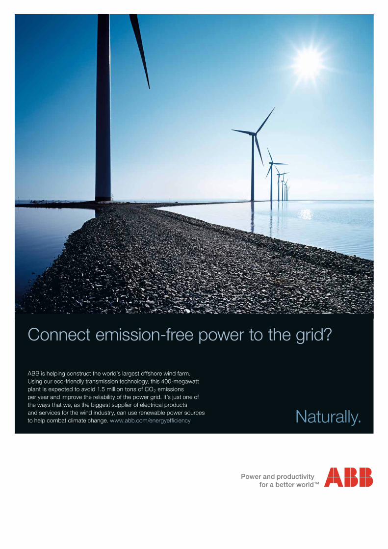
Connect emission-free power to the grid?
Naturally.
ABB is helping construct the world’s largest offshore wind farm. Using our eco-friendly transmission technology, this 400-megawatt plant is expected to avoid 1.5 million tons of CO2 emissions per year and improve the reliability of the power grid. It’s just one of the ways that we, as the biggest supplier of electrical products and services for the wind industry, can use renewable power sources to help combat climate change. www.abb.com/energyeffi ciency
a