frontier 1 direct observation of vortices in superconductors · 3. observation of vortices in...
TRANSCRIPT

4 JSAP International No.2 (July 2000)
Direct Observation ofVortices in Superconductorsby Using a Field-Emission Electron Microscope
havior at pinning centers was a dream of elec-
tron microscopists for almost 40 years.1-3), and
was finally realized4) by utilizing the phase in-
formation provided by a bright field-emission
electron beam.5-7)
2. Observation PrincipleThe principle behind the observation of
vortices is based on the use of the phase infor-
mation of an electron wave transmitted
through magnetic fields of vortices.8) The phase
shift of electron waves due to electromagnetic
fields can be derived using the Schrödinger
equation. When the effect of electromagnetic
fields on electron waves is weak, the relative
phase shift ∆S between two beams starting
from the same point, passing through points A
and B in electromagnetic fields (A, V), and com-
bining at another point is calculated as follows.
S = (1/ h) o (mv - eA)ds = (1/ h) o ( 2meV - etA)ds....(1)
Here t is the unit tangent vector of the
electron trajectory and the integration is car-
ried out along a closed loop connecting the
two electron trajectories. This equation shows
that the phase shift in an electron beam is de-
termined by electromagnetic potentials (A, V)
rather than electromagnetic fields (E, B).
Aharonov and Bohm asserted that an elec-
tron beam can be affected physically (phase-
shifted) by potentials even when it passes
through field-free regions on both sides of an
infinitely long solenoid and is therefore subjected
to no forces.9) This Aharonov-Bohm effect was
confirmed by using toroidal ferromagnets.10)
Akira TONOMURAAdvanced Research Laboratory, Hitachi, Ltd.
Hatoyama, Saitama 350-0395, Japan
CREST, Japan Science and Technology Corporation
Kawaguchi, Saitama 332-0012, Japan
perconductivity due to the dissipation. To in-
crease the critical current at which vortices be-
gin to move, we need to fix them in place. The
mechanism of the vortex pinning, however, is
not well understood because it is both micro-
scopic and complicated. The efforts to develop
practical superconducting materials with large
critical currents have, therefore, largely been
processes of trial and error.
The direct observation of the vortex be-
1. IntroductionVortices are closely related not only to the
fundamentals of superconductors but also to
their practical applications of superconductors.
When we want to use a type II superconduc-
tor, for example, as a dissipation-free conduc-
tor of a large electric current, we need to keep
vortices from moving due to the Lorentz force
exerted on them by the current. Otherwise, the
voltage difference induced by the movement
of magnetic flux eventually breaks down su-
Fig. 1. Phase shift of electron beams enclosing magnetic fluxA relative phase shift between two electron beams starting from a source point, passing through points A and B in amagnetic field, and combining at an observation point is proportional to the magnetic flux enclosed by the two beampaths.
Frontier 1
AbstractA dissipation-free current can be obtained in a superconductor only when the tiny magnetic vortices,which penetrate a superconductor
when a magnetic field is applied, are pinned down against the current-induced force. These vortices in superconductors have become dynamically
observable by Lorentz microscopy using a 300-kV field-emission transmission electron microscope. As material defects can be observed while the
vortices are being observed, the vortex pinning phenomena critical to the practical applications of superconductors can now be microscopically
and dynamically observed.
Source
Lens
Magnetic field
Prism
A B
4 JSAP International No.2 (July 2000)
JSAP International No.2 (July 2000) 5
This principle has been used to observe
the microscopic distributions of electromagnetic
fields. To be more specific, the thickness distri-
bution of a specimen uniform in material can
in principle be observed because the phase of
an electron wave is shifted by the inner poten-
tial of the specimen when the wave passes
through it. For thickness changes in the atomic
range, though, the phase shift calculated from
Eq. (1) is smaller than 2π. More precise mea-
surements of the electron phase became fea-
sible with the development of a “coherent”
field-emission electron beam and electron ho-
lography.8) In fact, thickness changes due to
monatomic steps11) and carbon nanotubes12)
have actually been detected as phase shifts of
the order of 1/100 of 2π.
In the case of pure magnetic fields, the
phase shift ∆S due to vector potentials can also
be calculated from the magnetic flux Φ pass-
ing through the closed loop connecting the two
trajectories:
S = - o Ads = - BdS = -he
he
h e ....(2)
When the phase distribution due to mag-
netic fields is displayed as an interference mi-
crograph obtained through the electron holog-
raphy process,8) it can be interpreted in the fol-
lowing straightforward way.
1. Contour fringes in the interference micro-
graph indicate magnetic lines of force, since
there is no relative phase shift (∆S) between
two beams passing through two points
along a magnetic line (see Fig. 1).
2. Contour fringes show magnetic flux in units
of h/e, since the phase difference between
two beams enclosing a magnetic flux of h/e
is 2π.
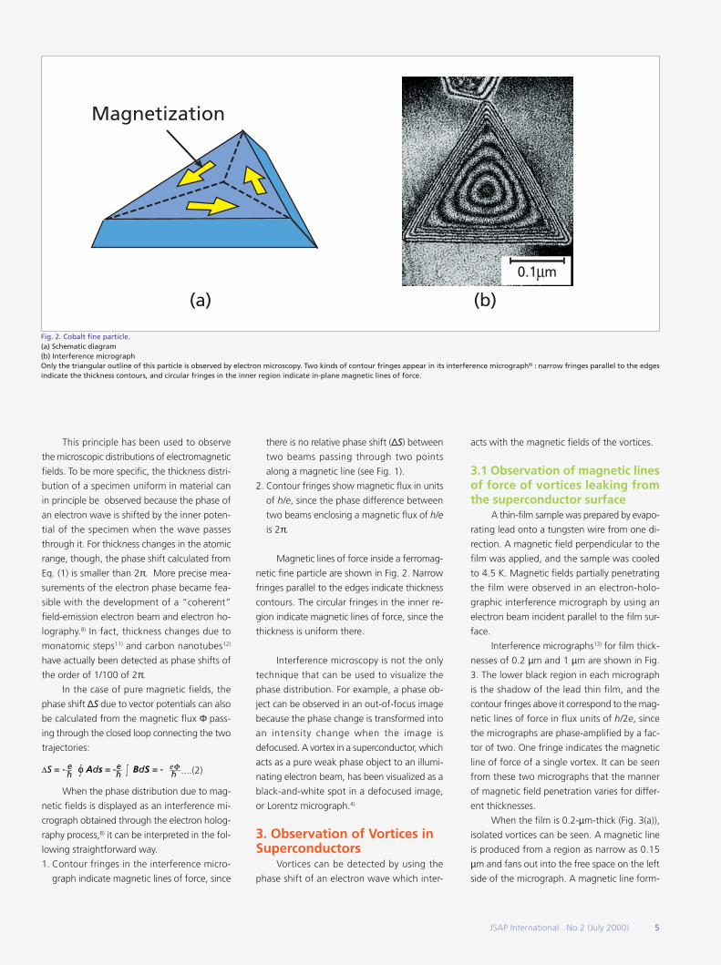
Magnetic lines of force inside a ferromag-
netic fine particle are shown in Fig. 2. Narrow
fringes parallel to the edges indicate thickness
contours. The circular fringes in the inner re-
gion indicate magnetic lines of force, since the
thickness is uniform there.
Interference microscopy is not the only
technique that can be used to visualize the
phase distribution. For example, a phase ob-
ject can be observed in an out-of-focus image
because the phase change is transformed into
an intensity change when the image is
defocused. A vortex in a superconductor, which
acts as a pure weak phase object to an illumi-
nating electron beam, has been visualized as a
black-and-white spot in a defocused image,
or Lorentz micrograph.4)
3. Observation of Vortices inSuperconductors
Vortices can be detected by using the
phase shift of an electron wave which inter-
acts with the magnetic fields of the vortices.
3.1 Observation of magnetic linesof force of vortices leaking fromthe superconductor surface
A thin-film sample was prepared by evapo-
rating lead onto a tungsten wire from one di-
rection. A magnetic field perpendicular to the
film was applied, and the sample was cooled
to 4.5 K. Magnetic fields partially penetrating
the film were observed in an electron-holo-
graphic interference micrograph by using an
electron beam incident parallel to the film sur-
face.
Interference micrographs13) for film thick-
nesses of 0.2 µm and 1 µm are shown in Fig.
3. The lower black region in each micrograph
is the shadow of the lead thin film, and the
contour fringes above it correspond to the mag-
netic lines of force in flux units of h/2e, since
the micrographs are phase-amplified by a fac-
tor of two. One fringe indicates the magnetic
line of force of a single vortex. It can be seen
from these two micrographs that the manner
of magnetic field penetration varies for differ-
ent thicknesses.
When the film is 0.2-µm-thick (Fig. 3(a)),
isolated vortices can be seen. A magnetic line
is produced from a region as narrow as 0.15
µm and fans out into the free space on the left
side of the micrograph. A magnetic line form-
Fig. 2. Cobalt fine particle.(a) Schematic diagram(b) Interference micrographOnly the triangular outline of this particle is observed by electron microscopy. Two kinds of contour fringes appear in its interference micrograph8) : narrow fringes parallel to the edgesindicate the thickness contours, and circular fringes in the inner region indicate in-plane magnetic lines of force.
JSAP International No.2 (July 2000) 5
Magnetization
(a) (b)
0.1 m

6 JSAP International No.2 (July 2000)
Fig. 4. Principle behind vortex observation.An incident electron wave is phase-shifted, or deflected, by the magnetic fields of vortices. In the defocusedimage, a vortex appears as a spot consisting of black-and-white contrast (Lorentz microscopy).
Fig. 3. Interference micrographs of magnetic lines of force leaking outside from vortices in a thin film of lead (phaseamplification: A× 2).(a) Film thickness = 0.2µm(b) Film thickness = 1.0µmOne contour fringe corresponds to the magnetic flux of one vortex, or h/2e. Individual vortices penetrate the film thinnerthan 0.5µm (mixed state), but bundles of vortices penetrate the thicker film (intermediate state).
Electron Wave
Vortices
Defocused image
ing an arc is also seen on the right. It is a mag-
netic line connecting an antiparallel pair of vor-
tices. This vortex and antivortex pair was pre-
sumably created by thermal excitation due to
the Kosterlitz-Thouless transition and is thought
to be frozen to be pinned.
Magnetic lines of force penetrate a thicker
film not as individual vortices but as bundles of
vortices. No vortex pairs are seen in Fig. 3(b).
This can be interpreted as follows: when a
strong magnetic field is applied to a thick film
of lead, which is a type I superconductor, the
film is divided into normal and superconduct-
ing domains (intermediate state). Magnetic lines
of force can pass through normal regions. Since
a normal region is surrounded by a supercon-
ducting region, the total flux is quantized to
an integral multiple of h/2e. An extremely thin
film, however, looks as if it were a type II su-
perconductor.
3.2 Observation of vortices insidesuperconductors
Vortices inside a superconductor can be
observed when an electron beam passes
through a thin-film sample.14) The experimen-
tal arrangement for observing vortices in a su-
perconductor is shown in Fig. 4. When a su-
perconducting thin film is tilted and a magnetic
field is applied horizontally, electrons passing
through vortices in the film are phase-shifted,
or deflected, by the magnetic fields of the vor-
tices. Consequently, when the phase distribu-
tion is observed as an interference micrograph,
projected magnetic lines of force can be ob-
served.15) However, by using this method it is
not easy to observe dynamics of vortices. This
can be done more easily by using Lorentz mi-
croscopy, in which vortices can be observed by
simply defocusing the electron microscopic
image. That is, when the intensity of electrons
is observed in a out-of-focus plane, a vortex
appears as a pair of bright and dark contrast
features ( Fig. 4).
A. Vortex depinning at differentdefects
Lorentz microscopy can reveal when and
how vortices are depinned when a driving force
is applied and increased. An example is shown
in Fig. 5. Lines of point defects (black dots in
Fig. 5) in a thin film of Nb were produced by
irradiating it with a focused Ga-ion beam and
changing the irradiation dose from line to line.
The dependence of the pinning force on the
ion doses producing the defects was investi-
gated by observing behavior of the vortices
when the driving force was increased by chang-
ing the applied magnetic field.
When a magnetic field of 100 G was ap-
plied, vortices were produced so close together
that the vortices pinned at the defects could
not be distinguished from unpinned vortices.
When the magnetic field was decreased, only
unpinned vortices began to leave the film but
weakly pinned vortices also began to move:
vortices hopped from one defect to another
along a defect line as if they were jumping over
stepping stones.
6 JSAP International No.2 (July 2000)
2 m
2 m
(a)
(b)

JSAP International No.2 (July 2000) 7
It can be seen from the Lorentz micro-
graph that all the unpinned vortices left the
film during this experiment and that vortices
pinned at defects produced by the ion irradia-
tion with the dose of 1000 times larger than
the unit dose did not move at all. No vortices
remained trapped at defects produced by irra-
diation with less than 10 times the unit dose.
For the defects produced by irradiation with
20- and 70 times doses, some of the pinned
vortices were trapped at the defects depend-
ing on the ion dose.
If the critical current is to be increased, all
the vortices have to be pinned. When there are
many defects, vortices are pinned by them. Too
many defects lead to the destruction of the su-
perconductivity, but there are other factors in-
fluencing the vortex pinning effect. The inter-
action between vortices, for example, plays an
important role in increasing critical current, es-
pecially when the magnetic field is strong.
B. Effect of vortex-vortex interac-tion on vortex pinning
When a weak magnetic field (< 7 G) was
applied to a thin film of Nb containing widely
spaced defects with fairly strong pinning forces
(ion dose of 70 times the unit dose), vortices
pinned at the defects did not begin to move
easily, while unpinned vortices far from defects
began to move freely. Vortices passing near the
defects at which other vortices were pinned,
however, were deflected by the magnetic re-
pulsive force between the pinned vortices and
the moving ones. Even unpinned vortices in
general did not move smoothly but hopped
from one point to another due to the exist-
ence of weak pinning centers inherent in Nb
samples, making the chance of vortices to col-
lide with the vortices trapped at the defects at
a high speed. In that case, an additional vortex
sometimes entered a defect. However, two
trapped vortices were unstable since the de-
fect radius (150 Å) was smaller than that of a
vortex (300 Å) and consequently in a few sec-
onds one escaped from the defect. On rare oc-
casions, vortices were even bounced from the
vortex trapped at a defect.
Very interesting phenomena were found
to occur when vortices were densely packed.
Vortices in general repel each other because of
their magnetic fields. When they are squeezed
by an external magnetic field, however, they
tend to form a closely packed lattice. In a ma-
terial containing strong pinning centers (e.g.
defects), vortices cannot form a single lattice
but instead form domains of lattices ( Fig. 6).
Fig. 5. Vortices trapped at lines of defects.The numbers below the micrograph indicate the Ga-ion doses in units of 10-10 C. Vortices are trapped more strongly atdefects produced by irradiation with larger doses.
Fig. 6. Vortex configuration near artificial point defects.Red spots indicate point defects produced by irradiation with a focused Ga-ion beam, and green spots indicate vortices.Vortices cannot form a single lattice since they are strongly trapped at the defects. When you look at this micrograph ata grazing angle, you can see domain boundaries of vortex lattices.
JSAP International No.2 (July 2000) 7
1 m
1 m
Frontier 1Direct Observation ofVortices in Superconductorsby Using a Field-Emission Electron Microscope

8 JSAP International No.2 (July 2000)
Fig. 7. Video frame during river flow.When a driving force is exerted on vortices that form domains of lattices due to the existence of point defects, thevortices begin to flow in rivers along the domain boundaries. The images of vortices in the rivers are blurred becausethose vortices moved while this frame was being shot.
Fig. 8. Lorentz micrographs of vortices.(a) H = 4H1 (H1: matching magnetic field)(b) H = H1
(c) H = 1/4H1
Purple vortices form a regular and rigid lattice at these specific magnetic fields. If one of these vortices is thermally depinned from its redsite by any chance, it cannot find a stable vacant site to hop to, thus producing a strong pinning effect.
When a force was exerted on such a con-
figuration of vortices and then increased, the
vortices flowed intermittently along the domain
boundaries.16) Each defect strongly pinned not
only a single vortex but also a domain of vorti-
ces. When the force reached a critical value,
the weakest regions of the vortex configura-
tion near the domain boundaries collapsed and
vortices in those regions flowed in rivers.
A video frame of such a vortex river is
shown in Fig. 7. The images of vortex inside
the river are blurred because those vortices
moved during the exposure time (1/30 sec) for
one frame. This flow stopped in less than a
second, forming a new domain structure. When
the increasing force reached another critical
value, they flowed again along new domain
boundaries. This process was repeated, result-
ing in intermittent vortex rivers here and there.
This was the first direct observation of vortices
flowing in the form of plastic flows.17), which
was confirmed by numerical simulations made
by Nori and his colleagues.18, 19)
C. Peculiar vortex pinning in anarray of pinning centers
The vortex pinning behaved completely
differently when the pinning centers were
densely arranged. This change in behavior oc-
curred especially for a regular array of artificial
point defects produced in a Nb thin film, where
vortices formed regular and rigid configurations
at specific values of magnetic fields. The net
pinning force increased at these specific mag-
netic fields, which is known as the peak effect
or the matching effect of the critical current,
found by macroscopic measurements.
Lorentz micrographs showing the configu-
rations of vortices relative to defect positions
are shown in Fig. 8. At the matching magnetic
field H1 (Fig. 8(b)), all the defects are occupied
by vortices and the lattice formed is a rigid
square one. The peak effect of the critical cur-
rent observed macroscopically can be explained
microscopically: when vortices form a stable
8 JSAP International No.2 (July 2000)
(a) (b) (c)
1 m

JSAP International No.2 (July 2000) 9
and regular lattice without vacancies, even if a
vortex is depinned from one pinning site due
to thermal excitation, it can find no vacant site
to move to. As a result, a stronger force is re-
quired to move the vortices.
Regular lattices were formed not only at
H = H1 (matching magnetic field, see Fig. 8(b))
but also at H = mH1/n (n and m; integers) as in
the case of H = 4H1 (Fig. 8(a)). In this vortex
configuration, defect positions forming a
square lattice were first occupied by vortices.
Then two vortices aligned in the vertical direc-
tion were inserted at every interstitial site, and
finally an additional vortex was inserted in the
middle of two adjacent defects located verti-
cally. Figure 8(c) shows the case at H = 1/4H1.
Vortices occupy every fourth site in the hori-
zontal direction, thus forming a centered (4 ×2) rectangle lattice. The reason the pinning force
as a whole becomes stronger at the specific
values of magnetic fields comes from the fact
that vortices form rigid and regular lattices.
When “excess” or “deficient” vortices
were produced at magnetic fields different from
the specific ones, such vortices could hop un-
der a weaker force (see Fig. 9), just like “elec-
trons” and “holes” that flow in a semiconduc-
tor. On the other hand, when a stronger force
was applied to vortices forming a regular lat-
tice, we observed a quite different flow of vor-
tices such as a simultaneous movement of vor-
tices along a lattice line.
D. Effect of antivortices on vortexpinning
We found unexpectedly during our ob-
servation experiments of vortices that
antivortices were often produced and had a
great influence on vortex pinning through the
processes of creation and annihilation of
antivortices.20) This happened in commonplace
processes, such as magnetization measure-
ments. When the magnetic field applied to a
Nb thin film was suddenly switched off, 90%
of the vortices left the film instantly, 10% are
pinned at weak pinning centers for a while,
and then gradually left the film by hopping.
When the magnetic field was then ap-
plied in the opposite direction and gradually
increased, the speed of the vortices increased.
Before they left the film, however, antivortices
appeared at the edges of the film and moved
towards the inner region of the film. Where
streams of vortices and antivortices collided
head-on, the antiparallel pairs at the heads of
the two streams annihilated each other.
Figure 10 shows two video frames, one
just before the annihilation of such a pair and
the other just after. When this pair annihilated
each other, the next vortex and antivortex ap-
proached by hopping and annihilated each
other. The results of macroscopic measure-
ments, such as magnetization measurements
of this state, provided no evidence of this phe-
nomenon because the total magnetic flux in
this field of view is zero as long as the sample
contains equal numbers of vortices and
antivortices. The annihilation process was re-
vealed only when the vortices and antivortices
were individually observed in real time.
Antivortices have a dramatic effect on
vortex pinning in the case where strong pin-
ning centers exist locally. In fact, when the mag-
netic field applied to a film was decreased, only
the unpinned vortices left the film. Then,
antivortices were produced from the film edges
even though the magnetic field was not ap-
plied in the opposite direction. The produced
antivortices approached the trapped vortices at
the pinning centers, collided head-on with them
and disappeared. The cause of the antivortices
is as follows: the magnetic lines of a trapped
vortex produced from the top surface of the
film went the long way beyond the film edge
and returned to the original vortex from the
back surface. Therefore, the direction of the
magnetic field was opposite at the film edge,
thus producing antivortices at the edge.
The mutual annihilation of a trapped vor-
tex and an incoming antivortex is equivalent to
the depinning of the trapped vortex. Therefore
when such an event occurs, the effective vor-
tex depinning can take place easily.
E. Unconventional vortex move-ments in high-Tc superconductors
The critical current of high-Tc supercon-
ductors is, in general, very low because both
the high temperature and the layered structure
of the materials make it easy for vortices in them
to move. When the vortex movement at the
depinning threshold was investigated by gradu-
ally increasing the magnetic field applied to
vortices in a high-Tc Bi2Sr2CaCu2O8+δ(Bi-2212)
superconductor, it was found that vortices
moved in quite different manners depending
on the applied magnetic field and the sample
temperature.21) In particular, the vortex move-
ment above 25 K was quite different from that
below this temperature.
Below 25 K all the vortices migrated slowly
at almost the same speed (Fig. 11(a)). Their
speed was 1.5 µm/s at 20 K, and decreased
rapidly when the temperature was lowered.
Above 25 K, however, vortices moved in differ-
ent forms of plastic flow depending on the
strength of the magnetic field. When it was
Fig. 9. Hopping interstitial vortex.When the applied magnetic field is different from the specific values, “excess” or “deficient”vortices are produced and can easily hop from one site to another just like the “electrons” or“holes” in a semiconductor when a driving force is applied to them.
JSAP International No.2 (July 2000) 9
1 m
Frontier 1Direct Observation ofVortices in Superconductorsby Using a Field-Emission Electron Microscope

10 JSAP International No.2 (July 2000)
Fig. 11. Movement of vortices in a thin film of Bi-2212(a) Migration movement below 25 K(b) Hopping movement above 25 KAt temperatures below 25 K a single vortex line is collectively pinned by a great number of oxygen defects and migratesslowly, assisted by thermal activation, when a driving force is applied. Above 25 K the oxygen defects no longer have apinning effect strong enough to withstand the increased thermal vibration of the vortices, and the pinning effect atlarger defects, which predominates at higher temperatures, results in hopping movement.
less than 1 G, the extremely sparse vortices
trapped at preferential points suddenly hopped,
one by one, from one point to another (Fig.
11(b)). The hopping was so frequent and sud-
den that the vortex image on video looked as
if it were blinking on and off.
When the magnetic field was increased,
the slow migration movement evident below
25 K remained the same but the individual hop-
ping movement above 25 K changed. The
forms of movement depended on how closely
the vortices were packed, and such forms as
filamentary flow, river flow, and lattice-domain
flow were observed as the magnetic field in-
creased.
This temperature-dependent change in
the kinds of vortex movement seen in high-Tc
superconductors can be interpreted as a result
of vortices being pinned at extremely tiny de-
fects, perhaps oxygen defects. The coherence
length (the radius of the normal core of the
vortex) is as small as 10Å in Bi-2212, whereas
in niobium it is 300 Å. Therefore, below 25 K
vortices are trapped by oxygen defects, which
act as densely distributed pinning centers. Since
a single vortex line penetrating a film 2000 Å
thick may be collectively pinned by more than
100 oxygen defects, it would appear to move
smoothly in the direction of the applied force.
Fig. 10. Annihilation of vortices and antivortices in a thin film of niobium.(a) Before annihilation(b) After annihilationWhen the magnetic field applied to the film is suddenly reversed, some vortices remain at weaklypinning defects while others begin to leave them. Antivortices begin to move in from the edges ofthe film. Where streams of vortices and antivortices collide head-on, the vortex-antivortex pairs ofthe heads of the two streams annihilate each other.
10 JSAP International No.2 (July 2000)
2 m
(a) (b)
(a)
(b)

JSAP International No.2 (July 2000) 11
This is because the thermally activated vortex
line would begin to be depinned from these
defects one by one on one side of the line and
to become pinned at new defects on the other
side. This would result in a migration that re-
sembles the movement of an object through a
viscous fluid.
Increased thermal vibration, however,
causes the vortices to be easily depinned from
small defects, and above 25 K the pinning ef-
fect of the oxygen defects practically vanishes.
The pinning at other larger and sparser defects,
which below 25 K is hidden by the strong pin-
ning at oxygen defects, predominates above
25 K because the pinning at larger defects is
less influenced by thermal vibration.
Since these larger defects are distributed
more sparsely, vortices depinned from one de-
fect hop to another. When vortices become
more abundant and form a closely packed lat-
tice, it becomes difficult for them to move in-
dividually. The specific forms of movement are
determined by the competition between ran-
dom pinning forces and vortex-vortex forces.
4. ConclusionVortices in superconducting thin films
were directly observed by monitoring the phase
of an electron beam passing through them. This
became possible after a bright electron beam
and phase-imaging techniques were developed.
The microscopic mechanism of vortex pinning
was investigated by using these techniques to
observe vortices depinned from material defects
by applying an increasing force. A 1000 kV
field-emission transmission electron micro-
scope22) has just been developed (Fig.12) and
will be used to explore many interesting fea-
tures of vortices in high-Tc superconductors. Ap-
plications of this new microscope are not lim-
ited to superconductivity. A bright electron
beam having an extremely short wavelength
will bring to the nanoscopic region in science
and technology new possibilities, especially in
high-precision measurements and in funda-
mental experiments in quantum mechanics, just
as other bright sources such as synchrotron
radiation sources and neutron sources now do.
Fig. 12. 1000-kV field-emission transmission electron microscope.
References1) H. Yoshioka: J. Phys. Soc. Jpn 21, 948 (1966).
2) D. Wohlleben: J. Appl. Phys. 38, 3341 (1967).
3) C. Colliex, B. Jouffrey and M. Kleman: Acta Crystallogr. A24, 692 (1968).
4) K. Harada, T. Matsuda, J. Bonevich, M. Igarashi, S. Kondo, G. Pozzi, U. Kawabe and A. Tonomura: Nature 360,
51 (1992).
5) A. V. Crewe, D. N. Eggenberger, D. N. Wall and L. N. Welter: Rev. Sci. Instrum. 39, 576 (1968).
6) A. Tonomura, T. Matsuda and J. Endo: Jpn. J. Appl. Phys. 18, 9 (1979).
7) T. Kawasaki, T. Matsuda, J. Endo and A. Tonomura: Jpn. J. Appl. Phys. 29, L5089 (1990).
8) A. Tonomura: Electron Holography - 2nd Edition, Springer, Heidelberg (1999).
9) M. Peshkin and A. Tonomura: Lecture Notes in Physics, 340 (Springer-Verlag, 1989).
10) A. Tonomura, N. Osakabe, T. Matsuda, T. Kawasaki, J. Endo, S. Yano and H. Yamada: Phys. Rev. Lett. 56, 792
(1986).
11) A. Tonomura, T. Matsuda, T. Kawasaki, J. Endo and N. Osakabe: Phys. Rev. Lett. 54, 60 (1985).
12) Q. Ru, G. Lai, K. Aoyama, J. Endo and A. Tonomura: Ultramicroscopy 55, 209 (1994).
13) T. Matsuda, S. Hasegawa, M. Igarashi, T. Kobayashi, M. Naito, H. Kajiyama, J. Endo, N. Osakabe, A. Tonomura
and R. Aoki: Phys. Rev. Lett. 62, 2519 (1989).
14) T. Hirayama, N. Osakabe, Q. Ru, T. Tanji and A. Tonomura: Jpn. J. Appl. Phys. 34, 3294 (1995).
15) J. E. Bonevich, K. Harada, T. Matsuda, H. Kasai, T. Yoshida, G. Pozzi and A. Tonomura: Phys. Rev. Lett. 70, 2952
(1993).
16) T. Matsuda, K. Harada, H. Kasai, O. Kamimura and A. Tonomura: Science 271, 1393 (1996).
17) G. W. Crabtree and D. R. Nelson: Phys. Today April, 38 (1997).
18) C. Reichhardt, J. Groth, C. J. Olson, S. B. Field and F. Nori: Phys. Rev. B 54, 16108 (1996).
19) C. Reichhardt, C. J. Olson and F. Nori: Phys. Rev. Lett. 78, 2648 (1997).
20) K. Harada, H. Kasai, T. Matsuda, M. Yamasaki and A. Tonomura: J. Electron Microsc. 46, 227 (1997).
21) A. Tonomura, H. Kasai, O. Kamimura, T. Matsuda, K. Harada, J. Shimoyama, K. Kishio and K. Kitazawa: Nature
397, 308 (1999).
22) T. Kawasaki, T. Yoshida, T. Matsuda, N. Osakabe, A. Tonomura, I. Matsui and K. Kitazawa: Appl. Phys. Lett. 76,
1342 (2000).
JSAP International No.2 (July 2000) 11
Frontier 1Direct Observation ofVortices in Superconductorsby Using a Field-Emission Electron Microscope