from sketch to sketchup - wordpress.com · fig. 10 conceptual sketchup model (author, 2013) fig. 11...
TRANSCRIPT

From Sketch to SketchUp
--- Reflecting the application of drawing and computer
aided architecture design (CAAD) on studio work
Course: ARC 6989 Reflections on Architectural Design
Tutor: Carolyn Butterworth,
Student: Yujiao Xia (MAAD)
Registration No: 120185469
Date: April 9, 2013

ARC 6989 Reflections on Architectural Design Yujiao Xia
1
List of figures
Fig. 1 Main line of communication……………………………………………………….6
Fig. 2 First impression: canal and bridges…………………………………………...……7
Fig. 3 Network of leisure area in Shipley……………………………………………....…8
Fig. 4 Site collage…………………………………………………………………………9
Fig. 5 Site………………………………………………………………………………...10
Fig. 6 Section of the site…….……………………………………………….…………..11
Fig. 7 Bridges on site………………………………………………………………….....12
Fig. 8 Conceptual sketch: slope and bridge…………………………………………..….12
Fig. 9 Conceptual sketch: roof………………………………………………………..….12
Fig. 10 Conceptual SketchUp model………………………………………………….…13
Fig. 11 Comparison of three conceptual SketchUp model………………………………13
Fig. 12 SketchUp model………………………………………………………………....14
Fig. 13 Eco-bridge 1………………………………………………………………..……14
Fig. 14 Section of eco-bridge 1……………………………………………….…………15
Fig. 15 Sketch of the eco-bridge structure………………………………………....…….15
Fig. 16 Eco-bridge 2………………………………………………………………….…..16
Fig. 17 Eco-bridge 3………………………………………………………………….…..16
Fig. 18 Perspective of eco-bridge 3……………………………………………………….17
Fig. 19 SketchUp model of eco-bridge 3…………………………………………………17
Fig. 20 Model of eco-bridge 3……………………………………………………...…….17
Fig. 21 Relationship between drawing and CAAD………………………………………18

ARC 6989 Reflections on Architectural Design Yujiao Xia
2
Contents
1. Introduction…………………………………………………………………………....3
2. Drawing and Computer aided architecture design (CAAD)……………..……………3
2.1 Drawing……………………………….…………………………………………3
2.2 Computer aided architecture design (CAAD)…………..……………………….4
3. Three aspects………………………………………………………………………..…5
3.1 Site perceiving…………………………………………………………………..5
3.2 Conceptual design...…………………………………………………………..…9
3.3 Design concept………………………………………………………………….13
4. Conclusion…………………………………………………………………………….18
5. Bibliography…………………………………………………………………………..20
6. List of figures……………………………………………………………………….…21

ARC 6989 Reflections on Architectural Design Yujiao Xia
3
1. Introduction
As architects, drawing is the first thing that they should learn. They inspire architects with visual
images, guide designers across confused thoughts, and finally present people beautiful and functional
buildings. The wide utilization of computers broadens the way of design. After the first use in 1960s,
Computer aided architecture design (CAAD) experienced a rapid developing. For instance, SketchUp,
a computer aided software, almost covered all aspects of architecture design, from the conceptual
design, drawing, modelling and rending.
Compare with traditional drawings, the outcomes of computers are orderly, clear, appearing to be
accurate or real and the process of architecture design is more efficient. From this angle, computer
aided architecture design injects vigor into conventional design and architectural education. However,
it also brings negative influence. The vivid rending by computer always covers the shortages in
architecture design.
After a brief introduction of drawing and computer aided architecture design, with the reflection
of my own experience of studio work, this essay will compare and contrast the applications of drawings
and CAAD in three aspects --- site perceiving, conceptual design and structure design, trying to find
their own advantages in different areas which can guide designers to design more effectively.
2. Drawing and Computer aided architecture design (CAAD)
2.1 Drawing
As people begin to design, drawing is an essential starting position (Edwards, 2008). The role of
drawing changes in different periods. In the Middle Ages, the drawings acted a double role which
combined plan and the elevation in rigid geometric layout. The design drawing and construction

ARC 6989 Reflections on Architectural Design Yujiao Xia
4
drawing are coincident. However, this situation changed in the Renaissance with the emergence of
study drawing which focused on schematic way and became a crucial method to analyze building
(Herbert, 1993). In that time, drawing also allowed architectural designers to experiment with the
expressive quality of building than did the Middle Ages (Robbins, 1994). Including schemata, in
modern architecture design, drawing infiltrates the whole process of design and construction. It is a
medium to communicate an idea with clients, a way to analyze building typology, a tool to represent a
magnificent building.
In total, Straightforwardness is the value of drawing because it brings a method to express
designer’s abstract and uncertain thought in a visual and clear way (Frascari & Starkey, 2007).
Potentially, graphic thinking (Laseau, 2000), which depends on these drawings or schemata to express
architects’ ideas, analyze the buildings and communicate with each other, is the essence of drawing.
2.2 Computer aided architecture design (CAAD)
As the name shows, computer aided architecture design, computer will help architects to design
buildings in an efficient way in the new century. Compare with the long history of architectural drawing,
the history of computer aided architecture design is short. The first application of CAAD is in 1963,
Ivan Sutherland’s work on the Sketchpad drawing system (Sutherland, 1963).
After that, with the speedy development of computer graphics, numerous software is invented
(Giddings & Horne, 2002). For example, SketchUp give a new way to explore the shape and layout of
the buildings; CAD improves efficiency of drawing various kinds of plans, sections and construction
drawings; V-ray benefit the representation of building; Photoshop helps to depict an outstanding view;
Illustrator makes diagrams clearer. They reform the way of design and make the process more efficient
not only in the design phase but also the construction period.

ARC 6989 Reflections on Architectural Design Yujiao Xia
5
It should be accepted that computer aided architecture design solve many problems that usually
happen in hand drawing, such as the accuracy and efficiency. However, it can not replace drawings in
design. The following three aspects will discuss how those two methods work in architectural design.
3. Three aspects
3.1 Site perceiving
Many architects consider that drawings are preconceived images which are the results of certain
ideas (Herbert, 1993). That is unilateral. In the period of site perceiving, when we do not familiar with
the site, drawings are the sources of the following design. Taking my studio project as an example,
hand drawings provide large information.
The topic of studio is architecture and ageing which is focusing on the elderly people’s life and
the relationship between the elder and the building. The site is in Shipley --- a small town in Bradford
in West Yorkshire, England.
After researching the basic information of Shipley, drawing the communication system (Fig. 1) on
a tracing paper that covered the master plan provide a convenient means to understand the layout of
the town: the green one is the railway, the brown one is the main road and the two blue lines are the
river and the Leeds – Liverpool Canal from above to below.

ARC 6989 Reflections on Architectural Design Yujiao Xia
6
Fig. 1 Main line of communication (Author, 2012)
Some people may question that this drawing is just tracing the fixed lines without thinking.
However, this work is the foundation stone of the next research. Drawing is a combination of different
elements, including the existing factors which are rigid like the medieval sketches and some schemata
which are thoughtful as the Renaissance drawings. Based on the traffic system, the designer got
familiar with Shipley. After visiting the small town, the designer was attracted by the canal area
because this was the energetic region which had diverse activities that can integrate the elder with the
youth. The various bridges along the canal offered different types of links between two sides (Fig. 2).
The map below (Fig. 2) tells people the functional zoning, the main traffic system and the first
impression about the town. Combining notes and schemata, graphic thinking penetrates the whole
development (Laseau, 2000). In this period, hand drawing is more convenient than computer to record
and analyze data.
ARC 6989 Reflections on Architectural Design Yujiao Xia
7
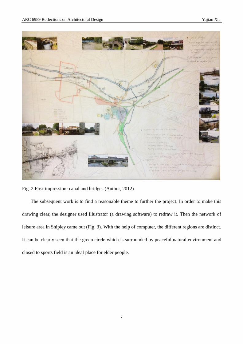
Fig. 2 First impression: canal and bridges (Author, 2012)
The subsequent work is to find a reasonable theme to further the project. In order to make this
drawing clear, the designer used Illustrator (a drawing software) to redraw it. Then the network of
leisure area in Shipley came out (Fig. 3). With the help of computer, the different regions are distinct.
It can be clearly seen that the green circle which is surrounded by peaceful natural environment and
closed to sports field is an ideal place for elder people.

ARC 6989 Reflections on Architectural Design Yujiao Xia
8
Fig. 3 Network of leisure area in Shipley (Author, 2013)
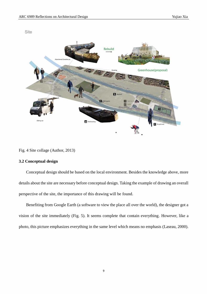
The next picture (Fig. 4) is the investigation of that area. With some small notable symbols, the
whole district is appearing. Considering the red part is previously greenhouse which was closed to the
sports field and surrounded by natural landscape, this area is worthy to transform into a nature center
that could attract people of all ages to be closed to the nature and enjoy the leisure time along the canal.
With the help of computer, the collage present the existing activities, facilities and environment
straightly.
ARC 6989 Reflections on Architectural Design Yujiao Xia
9
Fig. 4 Site collage (Author, 2013)
3.2 Conceptual design
Conceptual design should be based on the local environment. Besides the knowledge above, more
details about the site are necessary before conceptual design. Taking the example of drawing an overall
perspective of the site, the importance of this drawing will be found.
Benefiting from Google Earth (a software to view the place all over the world), the designer got a
vision of the site immediately (Fig. 5). It seems complete that contain everything. However, like a
photo, this picture emphasizes everything in the same level which means no emphasis (Laseau, 2000).

ARC 6989 Reflections on Architectural Design Yujiao Xia
10
Fig. 5 Site (Google Earth, 2013)
With careful observation and analysis of photos which were token from the site, a perspective
sketch (Fig. 6) about the site would present useful data. The section below present clearly of the
existing situation of the site in different colors --- blue canal and river, green abandoned greenhouse,
orange residential area and three purple rowing house. Besides, there are three meters of altitude
difference on site. Additionally, many bridges go across this region which makes it accessible.
Compare with the picture from Google Earth, the information on this sketch could be noticed (Fig. 6).

ARC 6989 Reflections on Architectural Design Yujiao Xia
11
Fig. 6 Section of the site (Author, 2013)
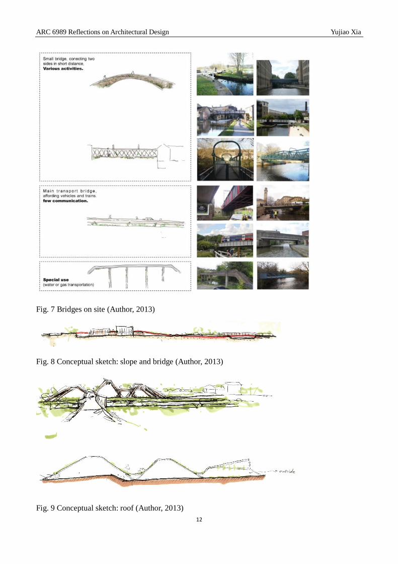
Considering the various bridges along the river, three types (Fig. 7) of bridges could be sorted.
The draft (Fig. 7), associated with the photos, shows the bridges act a vital role in that direct. Furthering
the research about the bridges, respecting the height difference on the site and considering the site as
a part of Shipley walk way, the concept (Fig. 8, Fig. 9) came out: extracting the image of the bridge as
the main pedestrian line which connects the two sides in three meters of height difference, surrounded
by the buildings which extend the roofs to the landscape. The vague lines and the different colors
represent the process of designer’s thoughts, and finally show a rational direction with vivid image.
The conceptual drawing and sketch are creative works that help designer sort out effective data
logically and trace the progress of the design immediately.
ARC 6989 Reflections on Architectural Design Yujiao Xia
12
Fig. 7 Bridges on site (Author, 2013)
Fig. 8 Conceptual sketch: slope and bridge (Author, 2013)
Fig. 9 Conceptual sketch: roof (Author, 2013)
ARC 6989 Reflections on Architectural Design Yujiao Xia
13
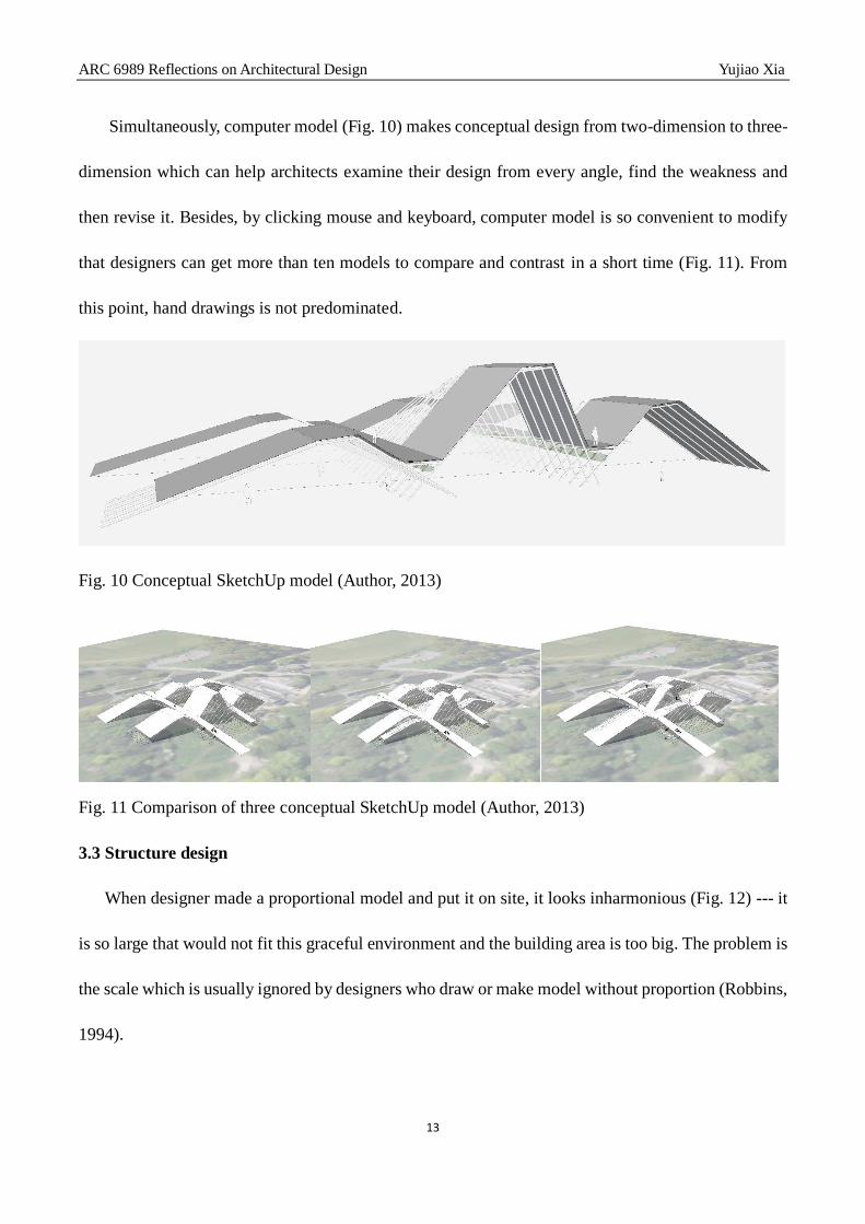
Simultaneously, computer model (Fig. 10) makes conceptual design from two-dimension to three-
dimension which can help architects examine their design from every angle, find the weakness and
then revise it. Besides, by clicking mouse and keyboard, computer model is so convenient to modify
that designers can get more than ten models to compare and contrast in a short time (Fig. 11). From
this point, hand drawings is not predominated.
Fig. 10 Conceptual SketchUp model (Author, 2013)
Fig. 11 Comparison of three conceptual SketchUp model (Author, 2013)
3.3 Structure design
When designer made a proportional model and put it on site, it looks inharmonious (Fig. 12) --- it
is so large that would not fit this graceful environment and the building area is too big. The problem is
the scale which is usually ignored by designers who draw or make model without proportion (Robbins,
1994).

ARC 6989 Reflections on Architectural Design Yujiao Xia
14
Fig. 12 SketchUp model (Author, 2013)
Why the construction is massive? The reason is that the eco-bridge (pedestrian line) which links
two parts with three meters of altitude difference is too high. If the structure is constructed as Fig. 13
shows, the height of the bridge would be more than three meters, including the corridor (Fig. 14) under
the bridge (more than 2.4M) and the growing media (more than 1M). In that case, the bridge would be
higher and the slope (Fig. 8) which conducts the people to the bridge would be longer. Consequently,
the building would become huge.
Fig. 13 Eco-bridge 1 (Author, 2013)

ARC 6989 Reflections on Architectural Design Yujiao Xia
15
Fig. 14 Section of eco-bridge 1 (Author, 2013)
Fig. 15 Sketch of the eco-bridge structure (Author, 2013)

ARC 6989 Reflections on Architectural Design Yujiao Xia
16
Computer model provides an apparent view of the shortage of this proposal (Fig. 14) while the
diagrams illustrate why it is not suitable (Fig. 13). Combining CAAD and drawing in design could
achieve maximum results with comparatively little effort. From the various draft of the eco-bridge
structure, the second idea (Fig. 16) came out. Although the space under the bridge is expanded, the
height of the bridge is still not changed. The essential problem does not be solved.
Fig. 16 Eco-bridge 2 (Author, 2013) Fig. 17 Eco-bridge 3 (Author, 2013)
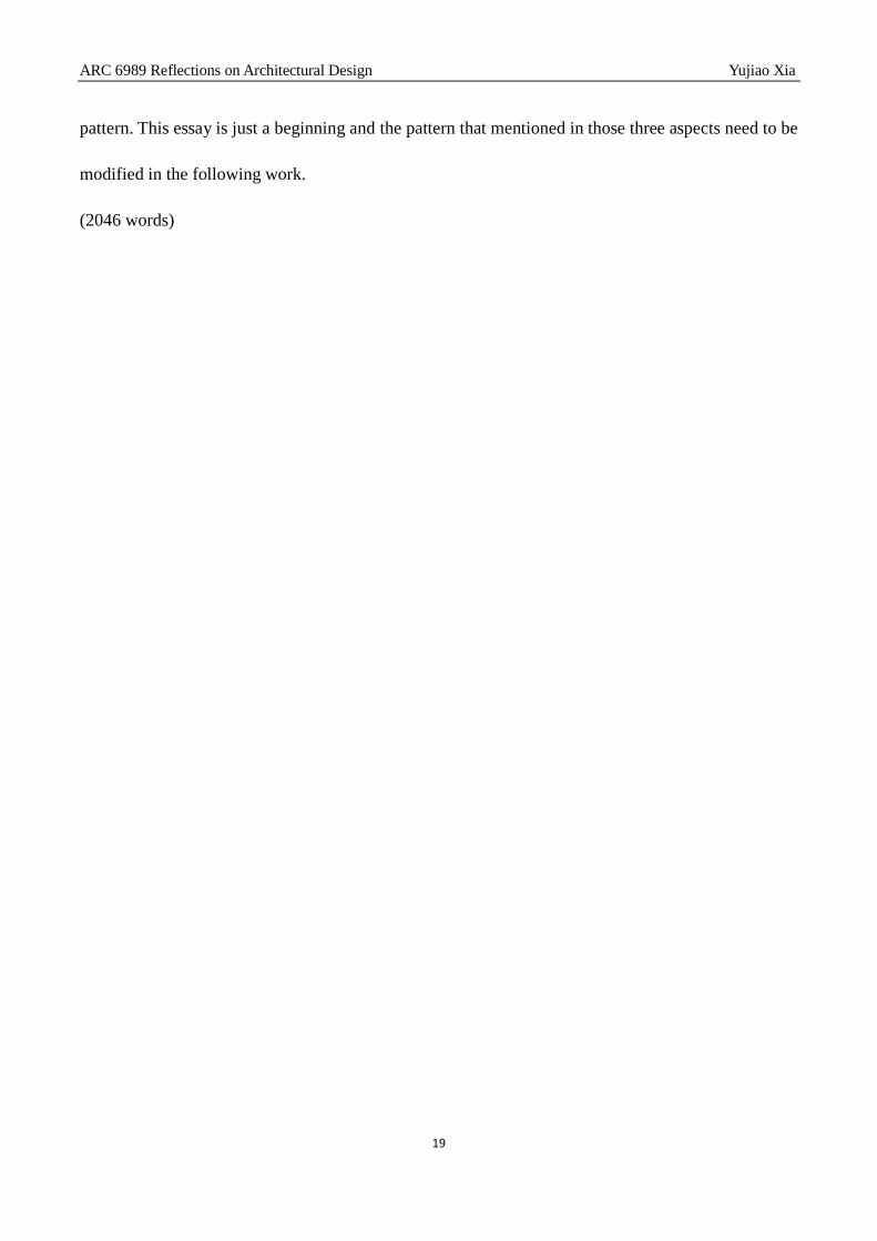
If the growing media could be moved, the height of the bridge would be reduced. With this concept,
designer tried to put two crossed structures which can hold the plants along the passage (Fig. 17). So
the previously green roof (Fig. 13, Fig. 16) which covered the corridor would be shifted to the sides.
Additionally, the space of the aisle under the bridge would be widened, and the bridge would be
spacious.
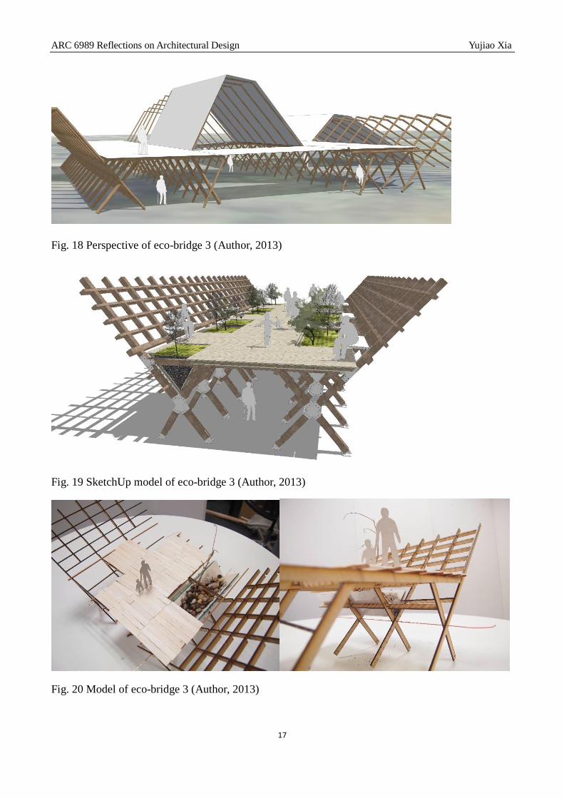
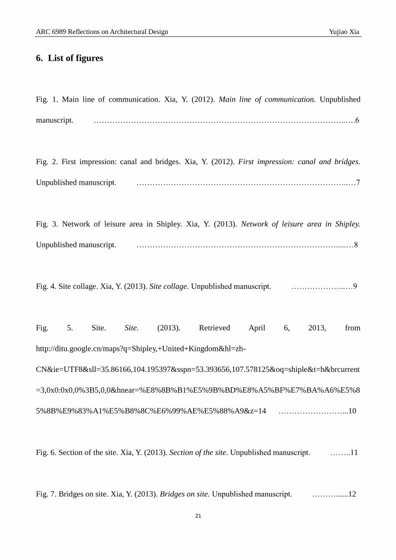
By making computer model (Fig. 18, Fig. 19) or physical model (Fig. 19), designer could check
to what extent their concept could be completed. From Fig. 18, the construction also seems a bit large,
the reason is that the width (3.6M) of the corridor is too wide. After reducing to 2.7M, on Fig. 19, the
whole structure looks more harmonious. Furthermore, when architects finish their model on the
computer, it is easy to get an exquisite representation of the building (Fig. 19).
ARC 6989 Reflections on Architectural Design Yujiao Xia
17
Fig. 18 Perspective of eco-bridge 3 (Author, 2013)
Fig. 19 SketchUp model of eco-bridge 3 (Author, 2013)
Fig. 20 Model of eco-bridge 3 (Author, 2013)

ARC 6989 Reflections on Architectural Design Yujiao Xia
18
4. Conclusion
After comprehensive reflection of my studio work, the methods of drawing and computer aided
architecture design cooperate with each other, permeating the whole design process (Fig. 21). The
abilities to instill complexity into a simple sketch and imbue an ordinary diagram with the nuances of
a design, such as extracting the image bridge to develop an eco-bridge, have significant meaning that
can help designers learn how to observe carefully, analyze deeply and think creatively (Jones, 2011).
In terms of CAAD, it is an effective tool to further architecture design which can analyze design factors,
check uncertain data, make accurate models and represent admirable pictures. Some of those
advantages could not be replaced by drawings, such as making precise models not to mention the mass
drawing or modelling of the building efficiently.
Fig. 21 Relationship between drawing and CAAD (Author, 2013)
In conclusion, comprehensive utilization of drawing and CAAD would make design efficiently. As
different architect has different habit, there is no particular standard to define the best way of applying
those two methods. With graphic thinking, designer need more and more practice to find an efficient
ARC 6989 Reflections on Architectural Design Yujiao Xia
19
pattern. This essay is just a beginning and the pattern that mentioned in those three aspects need to be
modified in the following work.
(2046 words)

ARC 6989 Reflections on Architectural Design Yujiao Xia
20
5. Bibliography
Edwards, B. (2008). Understanding architecture through drawing. Taylor and Francis.
Frascari, M., Hale, J., & Starkey, B. (Eds.). (2007). From models to drawings: imagination and
representation in architecture. London: Routledge.
Giddings, B., & Horne, M. (2002). Artists’ impressions in architectural design. London: Spon Press.
Herbert, D. (1993). Architectural study drawings. New York: Van Nostrand Reinhold.
Jones, W. (Eds.). (2011). Architects’ sketchbooks. London: Thames & Hudson.
Laseau, P. (2000). Graphic Thinking for architects and designers. New York: Wiley.
Robbins, E. (1994). Why Architects Draw. London: The MIT Press.
Sutherland, I. (1963). Sketchpad: a man-machine graphical communications system. Baltimore:
Spartan Books.
ARC 6989 Reflections on Architectural Design Yujiao Xia
21
6. List of figures
Fig. 1. Main line of communication. Xia, Y. (2012). Main line of communication. Unpublished
manuscript. …………………………………………………………………………………..….6
Fig. 2. First impression: canal and bridges. Xia, Y. (2012). First impression: canal and bridges.
Unpublished manuscript. ……………………………………………………………………..…7
Fig. 3. Network of leisure area in Shipley. Xia, Y. (2013). Network of leisure area in Shipley.
Unpublished manuscript. ………………………………………………………………….....…8
Fig. 4. Site collage. Xia, Y. (2013). Site collage. Unpublished manuscript. ………………...…9
Fig. 5. Site. Site. (2013). Retrieved April 6, 2013, from
http://ditu.google.cn/maps?q=Shipley,+United+Kingdom&hl=zh-
CN&ie=UTF8&sll=35.86166,104.195397&sspn=53.393656,107.578125&oq=shiple&t=h&brcurrent
=3,0x0:0x0,0%3B5,0,0&hnear=%E8%8B%B1%E5%9B%BD%E8%A5%BF%E7%BA%A6%E5%8
5%8B%E9%83%A1%E5%B8%8C%E6%99%AE%E5%88%A9&z=14 ……………………...10
Fig. 6. Section of the site. Xia, Y. (2013). Section of the site. Unpublished manuscript. ……..11
Fig. 7. Bridges on site. Xia, Y. (2013). Bridges on site. Unpublished manuscript. ………......12

ARC 6989 Reflections on Architectural Design Yujiao Xia
22
Fig. 8. Conceptual sketch: slope and bridge. Xia, Y. (2013). Conceptual sketch: slope and bridge.
Unpublished manuscript. ………………………………………………....................................12
Fig. 9. Conceptual sketch: roof. Xia, Y. (2013). Conceptual sketch: roof. Unpublished
manuscript. …………………………………………………....................................................12
Fig. 10. Conceptual SketchUp model. Xia, Y. (2013). Conceptual SketchUp model. Unpublished
manuscript. ………………………………………………………………………………….…13
Fig. 11. Comparison of three conceptual SketchUp model. Xia, Y. (2013). Comparison of three
conceptual SketchUp model. Unpublished manuscript. ……………………….………………13
Fig. 12. SketchUp model. Xia, Y. (2013). SketchUp model. Unpublished manuscript. ……….14
Fig. 13. Eco-bridge 1. Xia, Y. (2013). Eco-bridge 1. Unpublished manuscript. ………………14
Fig. 14. Section of eco-bridge 1. Xia, Y. (2013). Section of eco-bridge 1. Unpublished
manuscript. ……………………………………………….……………………………………15
Fig. 15. Sketch of the eco-bridge structure. Xia, Y. (2013). Sketch of the eco-bridge structure.
Unpublished manuscript. ………………………………………...............................................15
ARC 6989 Reflections on Architectural Design Yujiao Xia
23
Fig. 16. Eco-bridge 2. Xia, Y. (2013). Eco-bridge 2. Unpublished manuscript. ………….…..16
Fig. 17. Eco-bridge 3. Xia, Y. (2013). Eco-bridge 3. Unpublished manuscript. ………….…..16
Fig. 18. Perspective of eco-bridge 3. Xia, Y. (2013). Perspective of eco-bridge 3. Unpublished
manuscript. …………………………………………………………………………………….17
Fig. 19. SketchUp model of eco-bridge 3. Xia, Y. (2013). SketchUp model of eco-bridge 3.
Unpublished manuscript. ………………………………………………………………………17
Fig. 20. Model of eco-bridge 3. Xia, Y. (2013). Model of eco-bridge 3. Unpublished
manuscript. ……………………………………………………………………………....…….17
Fig. 21. Relationship between drawing and CAAD. Xia, Y. (2013). Relationship between drawing and
CAAD. Unpublished manuscript. ………………………………………………………………18