from: self -...
TRANSCRIPT

Tip: 37060 with 41351 41352 41361 41362 41371 Coach LED Lighting Date: 22-10-2017
http://members.ozemail.com.au/~rossstew/rms/marklin.html 1
Hi All,
The 37060 EP 3/6 K.Bay.Sts.B locomotive was manufactured in 1999 by Trix for the Märklin
assortment. I have had the locomotive since its release but haven’t run it on my layout because of a lack
of suitable coaches until I obtained in 24-06-2010, 2x 41351, 2x 41361 coaches and 1x 41371 baggage
car manufactured in 1996. I also obtained 2x 41352 and 1x 41362 coaches without the painted car wall
details which will allow me to make up an eight car train pulled by the 37060 locomotive. I still haven’t
run the train until now because the train didn’t have any lighting.
This is the first time I changed how I installed the LED lighting in the coaches and was very pleased with
the warm white even lighting I achieved. If I have sparked your interest please read on.
37060 Locomotive LED Light Upgrade with Red Rear Lights
This electric locomotive is unusual because it
has a smoke unit 72270 for coach heating which
I installed when I purchased it. The LED light
upgrade was done some time ago but for some
reason I didn’t document it.
The photo on the left shows the red LED
lighting at the rear of the locomotive and the
photo on the right shows the LED front lighting.

Tip: 37060 with 41351 41352 41361 41362 41371 Coach LED Lighting Date: 22-10-2017
http://members.ozemail.com.au/~rossstew/rms/marklin.html 2
37060 Locomotive continued
Caution: - If you want to
do this lighting upgrade
the body shell is held to
the chassis by four clips
and care should be taken
when removing the shell
because it is a tight fit. I
cut four thin plastic strips
to insert between the body shell and the chassis to prevent the clips catching while trying to remove the
shell see yellow arrows below.
The original bulb fitting is easy to remove once the brown cover at each end is removed. The screw at the
smoke unit end is covered by the electrical contact which has to be bent away from the top of the screw to
provide access to the screw head. Long nose pliers are required for this operation see red arrow.
The placement of the LED’s is important to
make use of the existing light pipes. The red
0603 LED needs to be placed at the centre and
the warm white PLCC2 LED off to the side
for the light pipe that goes to the top light.
To mount the LED’s in the correct position I glued some clear plastic film in a bent position to provide
insulation and support the red LED at the centre position with the white LED next to it as shown. The
LED’s were glued with hot melt glue after I had solder wires to the LEDs’
The current limiting resistors are 1k and are soldered in line with the wires that are soldered to the
cathode side of the LED’s. The resistors lay in the free bulb holder recess as shown above.

Tip: 37060 with 41351 41352 41361 41362 41371 Coach LED Lighting Date: 22-10-2017
http://members.ozemail.com.au/~rossstew/rms/marklin.html 3
37060 Locomotive continued
Wiring Diagram
The orange arrow indicates the +Plus solder pads at each end of the locomotive.
The yellow arrow indicates the rear light solder pad. The grey arrow indicates the front light solder pad.
Please note the two black wires in the photos above are for the red LED connections to the opposite end
of the locomotive for the main LED solder pad.
All resistors are 1k. The main warm white LED’s are PLCC2 size and the red LED’s are 0603 size.
Left photo lights are off. Middle photo, front direction white light and right photo, rear direction red light.
You may also get some red light bleeding into the top light but not enough to worry about.
Yellow Grey
Rear Front
+Plus 1k
1k
1k
1k
1k

Tip: 37060 with 41351 41352 41361 41362 41371 Coach LED Lighting Date: 22-10-2017
http://members.ozemail.com.au/~rossstew/rms/marklin.html 4
37060 Locomotive continued
I tried to capture the locomotive with smoke unit and front lights on.

Tip: 37060 with 41351 41352 41361 41362 41371 Coach LED Lighting Date: 22-10-2017
http://members.ozemail.com.au/~rossstew/rms/marklin.html 5
Coach LED Lighting
41371 Baggage Car Lighting
The baggage car with LED lights on has the 6080 decoder with collector shoe and wheel contacts and is
the power source for the entire train of eight coaches.
The collector shoe and wheel contacts are mounted on the rear bogie. I used gel super glue to glue two
rolled IC pins as a socket to the coupling pocket. Please note that the coupling should be removed when
the glue is used to prevent gluing the coupling into the coupling socket.
The wires on the socket are protected with heat shrink tube. You will also notice I have protected the
wires from rubbing on the axle by pre shrinking the tube on a 1mm diameter drill and used gel super glue
to glue the tube under the axle as shown yellow arrow. It is most important that the axle doesn’t rub on
the heat shrink tube causing drag to the coach. This method is used for each coach.
On the left I drilled a 2mm hole through the dividing panel and threaded the wires from the collector shoe
(black wire) and the wheel contacts (brown wire). For the wires on the right from the coupling socket I
soldered individual Rolled IC pins to be used as a plug into the lighting PCB.

Tip: 37060 with 41351 41352 41361 41362 41371 Coach LED Lighting Date: 22-10-2017
http://members.ozemail.com.au/~rossstew/rms/marklin.html 6
41371 Baggage Car continued
Using a 6080 decoder I set the code to #36 to match the locomotive address. I removed the motor wires
and the reversing coil centre black wire. The assembled diode bridge and 470uF capacitor with two rolled
IC pins for sockets for the +plus (orange arrow) and negative (black arrow) supply as shown above were
soldered to Vero board.
Decoder Wiring Diagram
The two yellow wires from the decoder were soldered together for the F0 function which will operate in
the forward or reverse direction.
The wires from the collector shoe and wheel contacts are soldered direct to the Vero board at the location
marked by the brown and red arrows top photo.
The Vero board PCB and decoder are held in position with hot melt glue.
6080 F0
470uF
35V
Decoder
~ ~ 15Vdc
+Plus
-Neg

Tip: 37060 with 41351 41352 41361 41362 41371 Coach LED Lighting Date: 22-10-2017
http://members.ozemail.com.au/~rossstew/rms/marklin.html 7
41371 Baggage Car continued
The Vero board lighting strip 160 mm length only required three warm white PLCC2 LED’s at a spacing
of approx. 56mm (2.2”) with the centre LED mounted in the centre of the body shell. The copper foils
under the LED’s have been cut using a 3mm drill. One 1k resistor is used for the current limiting of the
LED’s and on the foils +Plus and –Neg near the resistor is two Rolled IC pins used as sockets for the train
lighting supply.
The red arrow +Plus is linked across to the middle foil which connects to the anode of the first LED.
Two wires on the left are soldered to the Vero board lighting strip before gluing into position. At the other
end of the wires are a single rolled IC pin used as a plug with the plus marked with a white band on the
heat shrink.
The LED lighting strip is glued into the coach roof with hot melt glue at both ends and in the middle.
Wiring Diagram Baggage Car LED Lighting
Assembly Procedure for the Baggage Car
Lay the body shell next to the chassis as shown above. Connect the wires +Plus and –Neg on the left to
the power supply Vero board making sure the correct connections are made. On the right plug in the wires
from the coupling socket to the +Plus and –Neg sockets on the lighting strip. Carefully assemble the body
shell onto the chassis making sure no wires are pinched.
Having connectors allows for serviceability later on if required.
+Plus
-Neg
1k

Tip: 37060 with 41351 41352 41361 41362 41371 Coach LED Lighting Date: 22-10-2017
http://members.ozemail.com.au/~rossstew/rms/marklin.html 8
Coach General Notes
The baggage car on the left is the power source for all the train coach lights (socket connection) with the
first coach plugging into it.
As a rule I arrange all the coaches in the order I want the train to be assembled. This allows me to decide
which end I want to have the electrical plug and socket and to make sure I get the +Plus side on the same
side for the entire train to make joining the coaches consistent.
The wires must have freedom of movement and you will notice the wire loops are soldered to a small
Vero board inter connection panel. This was done for each coach making further service easy.
Coupling Modifications
As the electrical cables pass underneath the couplings I removed the
portion of the uncoupler bar (marked in orange) at the location of the
red arrow using side cutters. This allows for easier connection of the
plug and socket but also allows you to still uncouple the coaches.
PCB for Power Supply and LED Lighting (typical)
Seven lighting strips with the same dimensions are required see below. Photo is not to scale.
Each LED has a spacing of 27mm (1.1”) and equally spaced about the centre of the lighting strip. Under
each LED the copper foil has been cut to allow a series circuit for three LED’s see diagram below.
The LED PCB is used to mount the PLCC2 warm white LED’s and to supply power through the coach.
The black arrow is the –Neg connection and the cathode of the LED’s at each end of the strip connects to
the 1k limiting resistor. The orange wire is the +plus supply. In the middle of the PCB (red arrow) there is
a small wire link between the +plus and the anodes of the two LED’s, refer to wiring diagram below.
Wiring Diagram Coach LED Lighting (typical)
27
+Plus
-Neg
1k 1k
185

Tip: 37060 with 41351 41352 41361 41362 41371 Coach LED Lighting Date: 22-10-2017
http://members.ozemail.com.au/~rossstew/rms/marklin.html 9
Coach General Notes continued
Light Reflectors
Coaches 41361 and 41362 require the larger light reflector/diffuser Total = 3
Coaches 41351 and 41352 require the smaller light reflector/diffuser Total = 4
The reflectors are made from 80 GSM plain printing paper. I marked where the ribs that support the
window inserts from the curved part of the roof are and using scissors cut in from the edge 4~5mm.
Once all cuts have been made the reflectors can be inserted into the roof section of the coach without the
need for any glue. The window inserts support the paper and are a nice snug fit.
190
180
36
36

Tip: 37060 with 41351 41352 41361 41362 41371 Coach LED Lighting Date: 22-10-2017
http://members.ozemail.com.au/~rossstew/rms/marklin.html 10
41361 and 41362 Long Coaches
I used some left over LED lighting supports from the 73400 and 73401 lighting kits. The supports and
home made lighting strip are held in place with hot melt glue.
41361 above
41362 above
What is the New Method?
The photos above tell the story. You will notice I have the LED’s pointing up away from the coach
interior. The LED light is reflected and diffused giving a very even light with less intensity through out
the coach.
When I tried the LED’s pointing down there where hot spots of light directly below each LED.

Tip: 37060 with 41351 41352 41361 41362 41371 Coach LED Lighting Date: 22-10-2017
http://members.ozemail.com.au/~rossstew/rms/marklin.html 11
41351 and 41352 Shorter Coaches
Notice the LED lighting strip over hangs the interior detail by approx. 5mm at each end but the LED’s are
still positioned over the seating area at each end of the coach.
41351 above
41352 above
Tip: 37060 with 41351 41352 41361 41362 41371 Coach LED Lighting Date: 22-10-2017
http://members.ozemail.com.au/~rossstew/rms/marklin.html 12
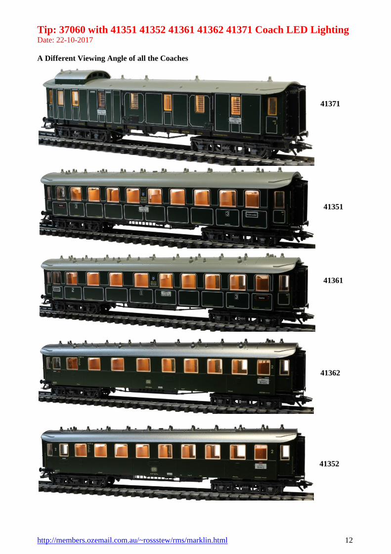
A Different Viewing Angle of all the Coaches
41371
41351
41361
41362
41352
Tip: 37060 with 41351 41352 41361 41362 41371 Coach LED Lighting Date: 22-10-2017
http://members.ozemail.com.au/~rossstew/rms/marklin.html 13
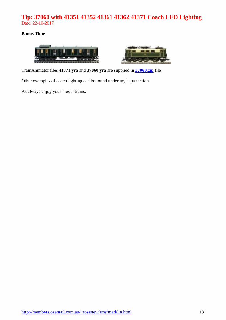
Bonus Time
TrainAnimator files 41371.yra and 37060.yra are supplied in 37060.zip file
Other examples of coach lighting can be found under my Tips section.
As always enjoy your model trains.