from design to reliable structures - hera.org.nz · background to the development of the new...
TRANSCRIPT

In partnership with:
From design to reliable
Presented by University of Sydney ProfessorDrBrian Uy, Western Sydney University Lecturer Dr Won-Hee Kang, and our General Manager Structural Systems Dr Stephen Hicks
15 September 2017
structures

www.hera.org.nz
Abstract – from design to reliable structuresDesign standards that lead to reliable structures are imperative for modern infrastructure. This paper will provide the background to the development of the new Australia-New Zealand standard for Composite Steel-Concrete Buildings, AS/NZS 2327. As part of the significant development of this standard which deals with composite slabs, beams, columns and systems a range of reliability studies were carried out in accordance with ISO 2394.
Although composite steel-concrete structures have been used in practice for over a century, the rapid advances in materials and innovative systems has required a rational approach to the development of prescriptive design approaches. Reliability studies on shear connectors, composite beams and composite columns were carried out to ensure that the effects of material variations and the effects of model inaccuracy are able to be reflected. These studies will be highlighted in this paper.
Furthermore, international developments in this area, in particular in Europe, the USA and Australasia has also highlighted the need for the development of databases of test data, which can be used by code developers in the future. Some brief examples of this will be given in this presentation.

www.hera.org.nz
Contents• Introduction
• Draft building standard for composite steel-concrete, ASNZS 2327
• Design of composite slabs
• Design of composite beams
• Design of composite columns
• Design of composite joints
• Design of composite floor systems
• System design for fire resistance
• Design for earthquake
• Appendices
• Conclusions and further research
• Acknowledgements
• References

0.1 Introduction

www.hera.org.nz
The concept of steel-concrete composition constructionGenerally produces structural behaviour where the overall response is greater than the sum of the parts.This concept holds true for composite beam behaviour where the introduction of longitudinal shearconnection can provide flexural stiffness and strength of a member which is greater than theconstituent parts, namely the structural steel section and the reinforced concrete slab.
Throughout the latter half of the twentieth century this concept has been further applied to compositesteel-concrete columns to produce column stiffnesses and strengths which are greater than the sum ofthe parts of the steel section and the reinforced concrete elements. These benefits have been furtherexploited by taking advantage of the confinement effects that steel tubes can provide to interiorconcrete infill and the subsequent benefits provided by the concrete infill on delaying local buckling ofthe steel shell.
This concept is now so widespread that in the last calendar year, more than 50 % of all tall buildingsconstructed worldwide, utilized composite frames, typically incorporating concrete filled steel columns(Council of Tall Buildings and Urban Habitat, 2016).
In Australia, builders of the recently completed Perth Tower (the tallest tower in Perth), chose to adoptcomposite construction throughout the entire structure and a concrete filled steel column solution. Inorder to secure this type of solution the builder pre-ordered and stored all spirally welded steel tubes inthe columns to ensure steel cost fluctuations were minimized and construction costs were able to becontrolled (Australian Steel Institute, 2010). The emphasis in Australia has been mainly focussed onconstruction economy when it relates to steel and steel-concrete composite structures.

www.hera.org.nz
CTBUH year in review: tall trends of 2015 and forecasts for 2016
www.hera.org.nz

www.hera.org.nz

0.2 Draft building standards for composite steel-concrete. ASNZS 2327

www.hera.org.nz
Draft for public comment
www.hera.org.nz
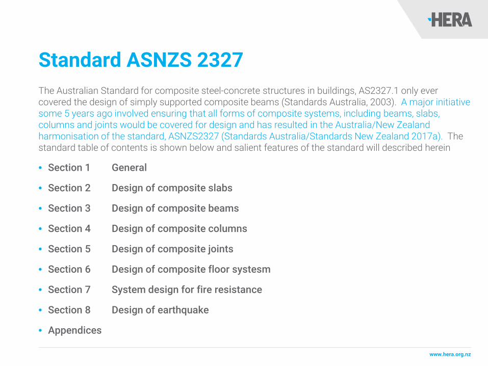
Standard ASNZS 2327The Australian Standard for composite steel-concrete structures in buildings, AS2327.1 only ever covered the design of simply supported composite beams (Standards Australia, 2003). A major initiative some 5 years ago involved ensuring that all forms of composite systems, including beams, slabs, columns and joints would be covered for design and has resulted in the Australia/New Zealand harmonisation of the standard, ASNZS2327 (Standards Australia/Standards New Zealand 2017a). The standard table of contents is shown below and salient features of the standard will described herein
• Section 1 General
• Section 2 Design of composite slabs
• Section 3 Design of composite beams
• Section 4 Design of composite columns
• Section 5 Design of composite joints
• Section 6 Design of composite floor systesm
• Section 7 System design for fire resistance
• Section 8 Design of earthquake
• Appendices

0.3 Design of composite slabs

www.hera.org.nz
Standard ASNZS 2327Section 2 of ASNZS2327 covers the comprehensive design of composite slabs. The intent of this section is to cover the strength and serviceability design of composite slabs utilising metal decking.
Issues including flexural strength, longitudinal shear and vertical shear provisions are covered in this section. Concepts of partial interaction are also considered and this section also links quite closely to that being proposed for testing in the Appendices of the standard. Furthermore, post-tensioned concrete construction is also extremely prominent in Australian buildings and recent innovations into post-tensioning concrete slabs with metal decking have been carried out.
One of the major issues is the changes that need to be introduced to deal with the presence of the metal decking for serviceability and strength provisions and these will be considered as part of this section, namely the concepts of non-uniform shrinkage (Al Deen et al., 2015).

www.hera.org.nz
Interlock and end anchorage design
www.hera.org.nz

www.hera.org.nz
Cross section, strain diagram and shrinkage profile at time

www.hera.org.nz
Capacity factor calibration for shear connectors
, , ,R d p d pr dM N z M= +where
,p dN =
,pr dM =
Capacity factor for steel (recommended as 0.9)
Plastic resistance moment of the profiled steel sheeting reduced by the axial force Np,d.
φ =
cφ =
τφ =
Capacity factor for concrete (recommended as 0.8)
Capacity factor for shear (recommended as 0.7)
Design axial force resisted by the profiled sheeting
According to ASNZS 2327, the design resistance of a composite slab is calculated as:
www.hera.org.nz
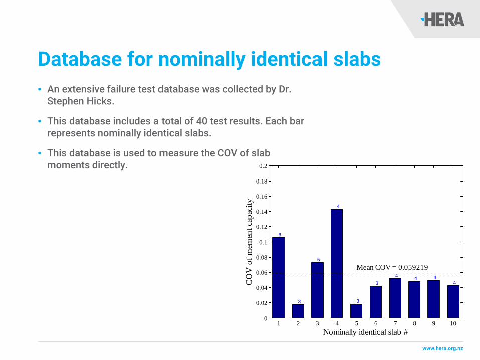
Database for nominally identical slabs• An extensive failure test database was collected by Dr.
Stephen Hicks.
• This database includes a total of 40 test results. Each bar represents nominally identical slabs.
• This database is used to measure the COV of slab moments directly.
1 2 3 4 5 6 7 8 9 100
0.02
0.04
0.06
0.08
0.1
0.12
0.14
0.16
0.18
0.2
Mean COV = 0.059219
Nominally identical slab #
CO
V o
f mem
ent c
apac
ity
6
3
5
4
3
34 4 4
4

www.hera.org.nz
Capacity factor calibration results
2.6 2.8 3 3.2 3.4 3.6 3.8 4 4.20
0.1
0.2
0.3
0.4
0.5
0.6
0.7
0.8
0.9
1
Target reliability index (β)
Cap
acity
fact
or ← φ=0.62585

0.4 Design of composite beams

www.hera.org.nz
Section 3 of ASNZ 2327This section covers the comprehensive design of composite steel-concrete beams. This section covers the design of composite beams, considering flexural strength, shear strength and combined actions as well as serviceability provisions.
Partial shear connection approaches are also highlighted for the design of simply supported and continuous beams.
This section also considers the design of composite beams using hollow core slabs as illustrated, (Uy and Bradford, 2007).

www.hera.org.nz
Design of composite beams

www.hera.org.nz

www.hera.org.nz
Design vertical shear capacity

www.hera.org.nz
Resistance of headed stud connectors

0.5 Design of composite columns

www.hera.org.nz
Design of composite columnsThis section covers the design of composite columns and closely follows the approach in the AS/NZS 5100 Part 6 (Standards Australia/Standards New Zealand, 2017b).
The design of composite columns for strength, stability incorporating axial force, uniaxial and biaxial bending is considered. In particular, the important effects of confinement are covered by this section.
Furthermore, the capacity factor for concrete in compression is proposed to be 0.65 based on reliability analyses using the design assisted by testing method provided in EN 1990 Annex D.8 (European Committee for Standardization, 2002). The reliability analyses were carried out for 1583 CFST columns included in Tao et al.’s database (Tao et al., 2008).

www.hera.org.nz
Capacity factors and squash load ration of steel
0.1 0.2 0.3 0.4 0.5 0.6 0.7 0.8 0.90
0.1
0.2
0.3
0.4
0.5
0.6
0.7
0.8
0.9
1
Squash load ratio of steel
Cap
acity
fact
ors
Capacity factor for steel (φ)Capacity factor for concrete (φc)
Average of φc

www.hera.org.nz
Extension of the reliability analysis considering international manufacturing tolerances
Parameter EN10219: 2006JIS G3444: 1994JIS G3466: 1988 KS D 3566: 1999KS D 3568: 2009
ASTM A500 AS/NZS 1163: 2009 GB/T 6728: 2002
Outside dimension for CHS (do) (m
m)-0.01 do
do≤50do>50
-0.25-0.005d
o
do ≤48do >51
-0.005do
-0.0075do
do≤50do>50
-0.8-0.01do
-(0.0098do + 0.09)
Outside dimension for RHS and SH
S (b) (mm)
b≤100100<b ≤2
00200<b
-0.01b-0.008b-0.006b
b≤100b>100
-1.5-0.015b
b ≤6464<b≤89
89<b≤140140<b
-0.5-0.64-0.76
-0.01b
b≤50b>50
-0.5-0.01b -(0.0076b + 0.12)
Thickness for CHS (t) (mm)
do≤406.4 and t≤5
do≤406.4 and t>5
do>406.4
-0.1t-0.5
-0.1t≤2
t≤33<t≤12
t>12
-0.3-0.1t-1.2
-0.1t -0.1t t≤10t>10
-0.1t-0.08t
Thickness for RHS and SHS (t) (m
m)
t≤5t>5
-0.1t-0.5
t≤3t>3
-0.3-0.1t -0.1t -0.1t t≤10
t>10-0.1t
-0.08t
Length (L) (mm)
L≤6m6m<L≤10
m10m<L
+5+15
+5+1mm/m
+nominal sizeNot specified. This study uses the tolerance in AS/NZS 1163
L≤14m14m<L≤18m
+6+10
L≤6m6m<L≤12m
+5+10

www.hera.org.nz
Rectangular stub CFST results for imported steel
2.6 2.8 3 3.2 3.4 3.6 3.8 4 4.20.5
0.6
0.7
0.8
0.9
1
1.1
1.2
1.3
1.4
1.5
Reliability index (β)
Cap
acity
fact
ors
COV of fy= 5%
COV of fy= 10%
COV of fy= 15%
COV of fy= 20%
2.6 2.8 3 3.2 3.4 3.6 3.8 4 4.20.5
0.6
0.7
0.8
0.9
1
1.1
1.2
1.3
1.4
1.5
Reliability index (β)
Cap
acity
fact
ors
COV of fy= 5%
COV of fy= 10%
COV of fy= 15%
COV of fy= 20%
(a) EN 10219; ϕ = 1.02, 0.98, 0.92 and 0.85 at β = 3.04
(b) JIS G 3444/JIS G 3466/KS D 3566/KS D 3568; ϕ = 1.00, 0.97, 0.91 and 0.84 at β = 3.04
2.6 2.8 3 3.2 3.4 3.6 3.8 4 4.20.5
0.6
0.7
0.8
0.9
1
1.1
1.2
1.3
1.4
1.5
Reliability index (β)
Cap
acity
fact
ors
COV of fy= 5%
COV of fy= 10%
COV of fy= 15%
COV of fy= 20%
2.6 2.8 3 3.2 3.4 3.6 3.8 4 4.20.5
0.6
0.7
0.8
0.9
1
1.1
1.2
1.3
1.4
1.5
Reliability index (β)
Cap
acity
fact
ors
COV of fy= 5%
COV of fy= 10%
COV of fy= 15%
COV of fy= 20%
(c) ASTM A 500; ϕ = 1.01, 0.97, 0.91 and 0.84 at β = 3.04
(d) AS/NZS 1163; ϕ = 1.00, 0.97, 0.91 and 0.84 at β = 3.04
2.6 2.8 3 3.2 3.4 3.6 3.8 4 4.20.5
0.6
0.7
0.8
0.9
1
1.1
1.2
1.3
1.4
1.5
Reliability index (β)
Cap
acity
fact
ors
COV of fy= 5%
COV of fy= 10%
COV of fy= 15%
COV of fy= 20%
(e) GB/T 6728; ϕ = 1.01, 0.97, 0.92 and 0.84 at β = 3.04
when ϕc is fixed to be 0.6

www.hera.org.nz
Circular stub CFST results for imported steel
when ϕc is fixed to be 0.6
2.6 2.8 3 3.2 3.4 3.6 3.8 4 4.20.5
0.6
0.7
0.8
0.9
1
1.1
1.2
1.3
1.4
1.5
Reliability index (β)
Cap
acity
fact
ors
COV of fy= 5%
COV of fy= 10%
COV of fy= 15%
COV of fy= 20%
2.6 2.8 3 3.2 3.4 3.6 3.8 4 4.20.5
0.6
0.7
0.8
0.9
1
1.1
1.2
1.3
1.4
1.5
Reliability index (β)
Cap
acity
fact
ors
COV of fy= 5%
COV of fy= 10%
COV of fy= 15%
COV of fy= 20%
(a) EN 10219; ϕ = 1.16, 1.11, 1.04 and 0.94 at β = 3.04
(b) JIS G 3444/JIS G 3466/KS D 3566/KS D 3568; ϕ = 1.14, 1.09, 1.01 and 0.92 at β = 3.04
2.6 2.8 3 3.2 3.4 3.6 3.8 4 4.20.5
0.6
0.7
0.8
0.9
1
1.1
1.2
1.3
1.4
1.5
Reliability index (β)
Cap
acity
fact
ors
COV of fy= 5%
COV of fy= 10%
COV of fy= 15%
COV of fy= 20%
2.6 2.8 3 3.2 3.4 3.6 3.8 4 4.20.5
0.6
0.7
0.8
0.9
1
1.1
1.2
1.3
1.4
1.5
Reliability index (β)
Cap
acity
fact
ors
COV of fy= 5%
COV of fy= 10%
COV of fy= 15%
COV of fy= 20%
(c) ASTM A 500; ϕ = 1.16, 1.11, 1.03 and 0.94 at β = 3.04
(d) AS/NZS 1163; ϕ = 1.16, 1.10, 1.03 and 0.94 at β = 3.04
2.6 2.8 3 3.2 3.4 3.6 3.8 4 4.20.5
0.6
0.7
0.8
0.9
1
1.1
1.2
1.3
1.4
1.5
Reliability index (β)
Cap
acity
fact
ors
COV of fy= 5%
COV of fy= 10%
COV of fy= 15%
COV of fy= 20%
(e) GB/T 6728; ϕ = 1.16, 1.11, 1.03 and 0.94 at β = 3.04

www.hera.org.nz
Rectangular long CFST results for imported steel
when ϕc is fixed to be 0.6
2.6 2.8 3 3.2 3.4 3.6 3.8 4 4.20.5
0.6
0.7
0.8
0.9
1
1.1
1.2
1.3
1.4
1.5
Reliability index (β)
Cap
acity
fact
ors
COV of fy= 5%
COV of fy= 10%
COV of fy= 15%
COV of fy= 20%
2.6 2.8 3 3.2 3.4 3.6 3.8 4 4.20.5
0.6
0.7
0.8
0.9
1
1.1
1.2
1.3
1.4
1.5
Reliability index (β)
Cap
acity
fact
ors
COV of fy= 5%
COV of fy= 10%
COV of fy= 15%
COV of fy= 20%
(a) EN 10219; ϕ = 1.01, 0.99, 0.97 and 0.93 at β = 3.04
(b) JIS G 3444/JIS G 3466/KS D 3566/KS D 3568; ϕ = 0.99, 0.97, 0.95 and 0.91 at β = 3.04
2.6 2.8 3 3.2 3.4 3.6 3.8 4 4.20.5
0.6
0.7
0.8
0.9
1
1.1
1.2
1.3
1.4
1.5
Reliability index (β)
Cap
acity
fact
ors
COV of fy= 5%
COV of fy= 10%
COV of fy= 15%
COV of fy= 20%
2.6 2.8 3 3.2 3.4 3.6 3.8 4 4.20.5
0.6
0.7
0.8
0.9
1
1.1
1.2
1.3
1.4
1.5
Reliability index (β)
Cap
acity
fact
ors
COV of fy= 5%
COV of fy= 10%
COV of fy= 15%
COV of fy= 20%
(c) ASTM A 500; ϕ = 1.01, 0.99, 0.97 and 0.93 at β = 3.04
(d) AS/NZS 1163; ϕ = 1.00, 0.99, 0.97 and 0.93 at β = 3.04
2.6 2.8 3 3.2 3.4 3.6 3.8 4 4.20.5
0.6
0.7
0.8
0.9
1
1.1
1.2
1.3
1.4
1.5
Reliability index (β)
Cap
acity
fact
ors
COV of fy= 5%
COV of fy= 10%
COV of fy= 15%
COV of fy= 20%
(e) GB/T 6728; ϕ = 1.01, 0.99, 0.97 and 0.93 at β = 3.04

www.hera.org.nz
Circular long CFST results for imported steel
when ϕc is fixed to be 0.6
2.6 2.8 3 3.2 3.4 3.6 3.8 4 4.20.5
0.6
0.7
0.8
0.9
1
1.1
1.2
1.3
1.4
1.5
Reliability index (β)
Cap
acity
fact
ors
COV of fy= 5%
COV of fy= 10%
COV of fy= 15%
COV of fy= 20%
2.6 2.8 3 3.2 3.4 3.6 3.8 4 4.20.5
0.6
0.7
0.8
0.9
1
1.1
1.2
1.3
1.4
1.5
Reliability index (β)
Cap
acity
fact
ors
COV of fy= 5%
COV of fy= 10%
COV of fy= 15%
COV of fy= 20%
(a) EN 10219; ϕ = 1.01, 0.99, 0.95 and 0.91 at β = 3.04
(b) JIS G 3444/JIS G 3466/KS D 3566/KS D 3568; ϕ = 1.00, 0.98, 0.94 and 0.90 at β = 3.04
2.6 2.8 3 3.2 3.4 3.6 3.8 4 4.20.5
0.6
0.7
0.8
0.9
1
1.1
1.2
1.3
1.4
1.5
Reliability index (β)
Cap
acity
fact
ors
COV of fy= 5%
COV of fy= 10%
COV of fy= 15%
COV of fy= 20%
2.6 2.8 3 3.2 3.4 3.6 3.8 4 4.20.5
0.6
0.7
0.8
0.9
1
1.1
1.2
1.3
1.4
1.5
Reliability index (β)
Cap
acity
fact
ors
COV of fy= 5%
COV of fy= 10%
COV of fy= 15%
COV of fy= 20%
(c) ASTM A 500; ϕ = 1.01, 0.99, 0.95 and 0.91 at β = 3.04
(d) AS/NZS 1163; ϕ = 1.00, 0.98, 0.95 and 0.91 at β = 3.04
2.6 2.8 3 3.2 3.4 3.6 3.8 4 4.20.5
0.6
0.7
0.8
0.9
1
1.1
1.2
1.3
1.4
1.5
Reliability index (β)
Cap
acity
fact
ors
COV of fy= 5%
COV of fy= 10%
COV of fy= 15%
COV of fy= 20%
(e) GB/T 6728; ϕ = 1.01, 0.99, 0.95 and 0.91 at β = 3.04

www.hera.org.nz
Design of composite columnsPerth Tower, 2012

www.hera.org.nz
Design of composite columns

www.hera.org.nz
Codes of practice models and reliability indices

www.hera.org.nz
Design of composite columnsFor RCFSTSs, CCFSTCs, and CESCs the AIJ (1997) and ACI 318 (2010) show the lowest standard deviations, making them more reliable predictors for deflection. Both AIJ (1997) and ACI (2010) use a capacity factor of 0.2 in the EI equations, which is far lower than the other codes.
The AS 5100.6 (2004) uses a factor of 1.0 and AS/NZS 2327 (Draft 2015) uses a factor of 0.6. From these results, a capacity factor of 0.2 provides the most reliable deflection results.

0.6 Design of composite joints

www.hera.org.nz
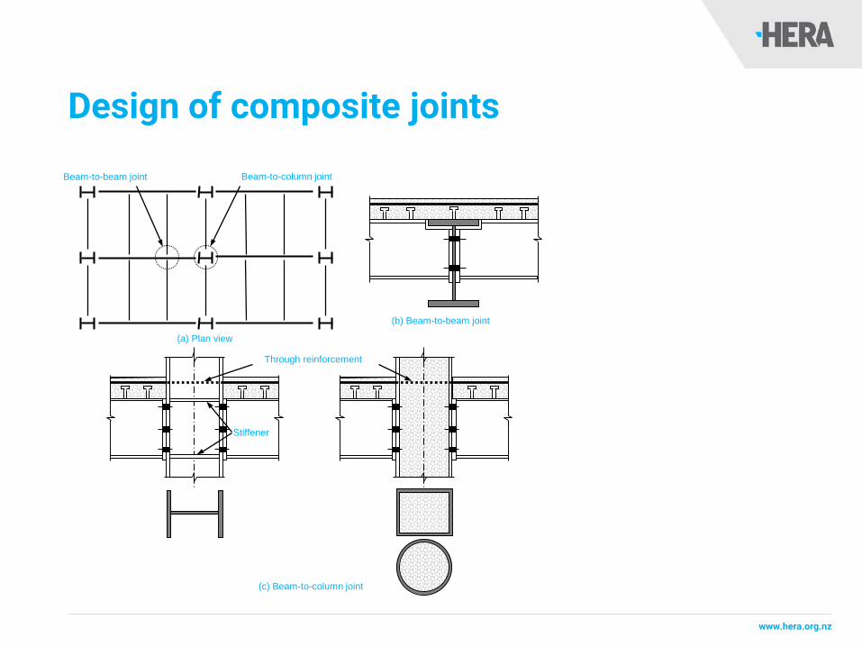
Design of composite jointsThis standard has also involved in the development of a section for strength and serviceability design of semi-rigid joints including beam-to-beam and beam-to-column joints as shown in Figure 9.
For beam-to-column joints, the column could be either open sections with/without stiffeners or hollow sections with/without infilled concrete.
The design of joints to hollow section columns is based on the stiffness model of Thai and Uy (2016) which was calibrated with experimental results of 44 available tests on bolted endplate beam-to-CFST column joints.
www.hera.org.nz
Design of composite joints
(c) Beam-to-column joint
Stiffener
(b) Beam-to-beam joint
(a) Plan view
Beam-to-beam joint Beam-to-column joint
Through reinforcement

www.hera.org.nz
Design of composite joints

0.7 Design of composite floor systems
www.hera.org.nz
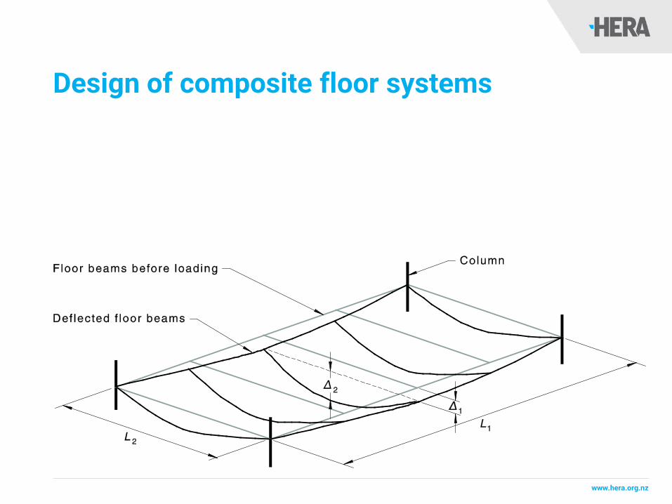
Design of composite floor systemsThe intent of this section is to address system behaviour particularly for deflections and vibrations for panels. This will then give designers the ability to take into account the beneficial effects of system behaviour in addressing these important serviceability provisions which sometimes penalize steel frame structures from a design perspective (Steel Construction Institute, 2012).
www.hera.org.nz
Design of composite floor systems

www.hera.org.nz
Occupant induced floor vibrations• Walking activities
• Syncronised crowd movement (dance floors, pop concerts etc)
Floor plan showing areas with different levels of floor response

0.8 System design for fire resistance

www.hera.org.nz
System design for fire resistenceThis section is also intended to give guidance on design for fire using a system based approach, which acknowledges that for indeterminate systems there is a significant degree of redundancy that provides additional structural capacity within a fire that is unable to be addressed considering single elements within a building. State of the art approaches for dealing with this will be provided herein (Steel Construction Institution, 2006 and Abu et al., 2011).

www.hera.org.nz
Design for fire resistance

www.hera.org.nz
System design for fire resistence
0.9 Design for earthquake
www.hera.org.nz
Design for earthquakeThis section covers the design for earthquake of composite frame systems.
One of the major elements of the section is the specific guidance provided to Australian and New Zealand designers in accordance with AS1170.4 and NZS1170.5 (Standards Australia 2004 and Standards New Zealand 2007).

www.hera.org.nz
Design for earthquake

10. Appendices

www.hera.org.nz
AppendicesThis section of the proposed standard is meant to provide standard test methods for a number of specific issues which are covered.
Push test methods for establishing the strength, stiffness and ductility of shear connectors will be outlined in this section as will test methods for establishing the strength characteristics of composite slabs incorporating profiled steel sheeting. In addition, provisions for evaluating design resistance from tests will also be presented.
Finally, ASNZS 2327 will be one of the first international composite design standards to present provisions for beams with both regular and isolated web-openings, thereby supporting the use of long-span cellular beams (Steel Construction Institution, 2011).

www.hera.org.nz

www.hera.org.nz

www.hera.org.nz

11. Conclusions and further research
www.hera.org.nz
Conclusions and further researchWhilst there is ongoing research into structural steel and some of the technical issues associated with materials and systems, it is felt that further research will be punctuated by approaches that provide paradigm shifts in the design of steel and steel-concrete composite building structures. Some of the more prominent issues that will promote these paradigm shifts include precast and prefabricated construction, de-constructability and new and higher performance materials.
In particular steel and steel-concrete composite framed buildings have the ability to be designed and constructed with deconstruction in mind. Advanced economies around the world are now looking toward reuse as a potential for addressing the issue of shortages in natural resources in future. Composite action has the ability to reduce steel usage and deconstruction has the ability to provide reuse options. Reduce and reuse strategies are far superior to recycling options and have the ability to provide much greater benefits to society from the perspectives of sustainability.

12. Acknowledgements

www.hera.org.nz
AcknowledgementsThe authors would like to thank the members of the BD-32 Committee for all their hard work to date; in particular, the Standards Australia Project Manager, Declan Robinson.
As members of the BD-32 Committee, the present authors have prepared this paper according to what they consider to be the significant changes to the existing AS 2327.1. However, the standard is still being prepared for ballot and, as a consequence of this, may be subject to change.
Any views expressed in this paper may not necessarily reflect those of the other members of the Committee, nor those of Standards Australia and Standards New Zealand

www.hera.org.nz
ASNZS 2327 Main Committee• Professor Brian Uy, Engineers Australia
(Independent Chairman)
• Dr Stephen Hicks, HERA, New Zealand (New Zealand Lead)
• Professor Mark Bradford, The University of New South Wales
• Professor Gianluca Ranzi, The University of Sydney
• Dr Subo Gowripalan, AIG
• Dr Linus Lim, FPAA
• Dr Peter Key, ASI
• Mr Daniel Acquero, ABCB
• Mr Kevin Cowie, SCNZ
• Mr Alexander Filonov, BOSMA
• Mr Kevin Huff, NPCAA
• Mr John Merrick, Consult Australia
• Dave McGuigan, MBIE, NZ
• Mr John Nichols, CCAA
• Mr Mr Scott Munter, SRIA
• Mr Anthony Ng, BOSMA

13. References

www.hera.org.nz
• Abu A.K., Ramanitrarivo V., Burgess I.W., (2011) Collapse Mechanisms of Composite Slab Panels in Fire, Journal of Structural Fire Engineering, 2 (3), 205-216.
• Al-Deen, S., Ranzi, G., Uy, B. (2015) Non-uniform shrinkage in simply-supported composite steel-concrete slabs. Steel and Composite Structures, 18(2), 375-394.
• Aslani, F., Uy, B., Tao, Z., Mashiri, F., (2015a) Behaviour and design of composite columns incorporating compact high-strength steel plates, Journal of Constructional Steel Research, 107, 94-110.
• Aslani, F., Uy, B., Tao, Z., Mashiri, F., (2015b) Predicting the axial load capacity of high-strength concrete filled steel tubular columns, Steel and Composite Structures, 19, 967-993.
• Aslani, F., Uy, B., Hicks, S., Kang, W.H., (2015c) Spiral welded tubes – imperfections, residual stresses, and buckling characteristics, The Eighth International Conference on Advances in Steel Structures, July 21–24, Lisbon, Portugal.
• Aslani F., Uy B., Hur J. and Carino P., (2017) Behaviour and design of hollow and concrete-filled spiral welded steel tube columns subjected to axial compression, Journal of Constructional Steel Research, 128, 261-288.
• Australian Steel Institute (2010) Perth tower agape to grand views, Steel Australia, 34 (6), 18-20.
• Council on Tall Buildings and Urban Habitat (2016) The Skyscraper Surge Continues in 2015, “The Year of 100 Supertalls”. CTBUH Year in Review: Tall Trends of 2015, and Forecasts for 2016, http://www.skyscrapercenter.com/research/CTBUH_ResearchReport_2015YearInReview.pdf accessed 15/05/2017.
• European Committee for Standardization (2002) EN 1990:2002 Eurocode: Basis of structural design, Brussels, 2002.
• Schouten, H. (2015) $80m hi-tech tower to replace Wellington’s Perth House, http://www.stuff.co.nz/business/67536882/80m-hi-tech-tower-to-replace-Wellingtons-BP-House, accessed 15/05/2017.
• Standards Australia (2003) Composite structures, Part 1: Simple supported beams, AS 2327.1:2003, New South Wales, Australia.
• Standards Australia (2007) Australian Standard, AS 1170.4—2007 Structural design actions Part 4: Earthquake actions in Australia.
• Standards Australia/Standards New Zealand (2017a) Composite Structures, AS/NZS 2327-2017, Sydney, Australia.
• Standards Australia/Standards New Zealand (2017b), AS/NZS 5100.6: 2017, Bridge Design, Part 6: Steel and composite construction, Sydney/Wellington, Australia/New Zealand.
• Standards New Zealand (2004) New Zealand Standard, NZS 1170.5—2004 Structural design actions Part 5: Earthquake actions in New Zealand.
• Steel Construction Institute (2006) Fire Safe Design: A New Approach to Multi-Storey Steel-Framed Buildings, SCI P288, United Kingdom.
• Steel Construction Institute (2011) Design of composite beams with large web openings, SCI P355, United Kingdom.
• Steel Construction Institute (2012) Design of floors for vibration: a new approach, SCI P354, United Kingdom.
• Tao Z., Uy B., Han L.H., He S.H., (2008) Design of concrete-filled steel tubular members according to the Australian Standard AS 5100 model and calibration, Australian Journal of Structural Engineering, 8 (3), 197-214.
• Thai H.T., Uy B., (2016) Rotational stiffness and moment resistance of bolted endplate joints with hollow or CFST columns, Journal of Constructional Steel Research, 126, 139-152.
• Thai H.T., Uy B., Yamesri, Aslani F., (2017) Behaviour of bolted endplate composite joints to square and circular CFST columns, Journal of Constructional Steel Research, 131, 68-82.
• Uy B. and Bradford M.A., (2007) Composite action of structural steel beams and precast concrete slabs for the flexural strength limit state, Australian Journal of Structural Engineering, 7, 123-133.