from analysis to design - tuhh · every possible event of the “world outside ... ltood/ooad –...
TRANSCRIPT

1LTOOD/OOAD – Verified Software Systems
From Analysis to Design

2LTOOD/OOAD – Verified Software Systems
Use Cases: Notation Overview
Actor A
Actor B
System X
UCExt
UCIncl
UCVar1
UCBase
UCVar2
«include»
«extend»
System boundary
Actor
Generalization
Extending case
Use case
Included case

3LTOOD/OOAD – Verified Software Systems
Paths, Scenarios, Processes
o Use case definitions are mostly an overlay of several
conditionally closely related paths.
o A certain path through a use case is called a scenario.
A scenario shows a particular set and combination of conditions
within the same use case, e.g., ordering some goods under
o scenario 1: All goes well.
o scenario 2: There are not enough goods.
o scenario 3: Credits are insufficient.
o Processes involving different use cases are shown in
workflows, e.g., from ordering to delivery and payment.
Interaction Diagrams
Activity Diagrams

4LTOOD/OOAD – Verified Software Systems

5LTOOD/OOAD – Verified Software Systems

6LTOOD/OOAD – Verified Software Systems

7LTOOD/OOAD – Verified Software Systems

8LTOOD/OOAD – Verified Software Systems

9LTOOD/OOAD – Verified Software Systems

10LTOOD/OOAD – Verified Software Systems

11LTOOD/OOAD – Verified Software Systems

12LTOOD/OOAD – Verified Software Systems
Interaction with External Systems
o Interaction with external systems can be represented in
four ways:
1. Show each interaction with external systems in the diagram.
2. Only show use cases for external interaction, if the other
system initiates the contact.
3. Only show system actors if they need the already identified use
cases.
4. Disallow systems as actors, concentrate on users.
Use external events to identify use cases not covered by actors. Find
every possible event of the “world outside” needing a reaction.

13LTOOD/OOAD – Verified Software Systems
Modeling System Structure

14LTOOD/OOAD – Verified Software Systems
Class Diagrams in Analysis
o Notation required for:
n Classes
n Relations:
o Multiplicity
o Roles
o Associations
o Aggregation
o Composition
n Generalization
n Objects
?

15LTOOD/OOAD – Verified Software Systems
o Conceptual view (analysis)
n classes represent the application concepts
n language and system independent
n few classes, few diagrams
o Design view (late analysis, early design)
n classes represent SW-interfaces
n describes the solution of difficult problems of the implementation
n structures the system in layers, subsystems and packages
o Implementation view (late design and programming)
n classes represent code in a programming language
n is directly mapped on the implementation
n example: mapping of associations
Three Views on OO-Modeling
Views are part of Unified Process, not of UML itself.

16LTOOD/OOAD – Verified Software Systems
Analysis: How to find Classes?
o First cut: Identify classes by nouns
n Categorize the nouns
n Remove nouns and concepts which do not represent
independent conceptual classes
n Choose meaningful and substantial class names
n Document each class in short (~1 defining sentence)

17LTOOD/OOAD – Verified Software Systems

18LTOOD/OOAD – Verified Software Systems

19LTOOD/OOAD – Verified Software Systems

20LTOOD/OOAD – Verified Software Systems
Analysis: Find Attributes
o Identify attributes following the noun method
o Check the attribute name
n Each attribute name should be
o a noun,
o chosen as concrete as possible,
o no homonym.
o Define the type of the attributes
n In the conceptual class diagram the type can remain
unspecified.
21LTOOD/OOAD – Verified Software Systems
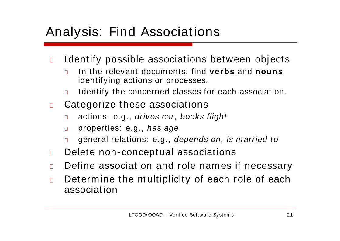
Analysis: Find Associations
o Identify possible associations between objects
n In the relevant documents, find verbs and nouns
identifying actions or processes.
n Identify the concerned classes for each association.
o Categorize these associations
n actions: e.g., drives car, books flight
n properties: e.g., has age
n general relations: e.g., depends on, is married to
o Delete non-conceptual associations
o Define association and role names if necessary
o Determine the multiplicity of each role of each
association

22LTOOD/OOAD – Verified Software Systems
Conceptual Modeling by Classes
o Definitional goals:
n conceptual perspective
o defining the application domain by
n capturing its relevant concepts (concrete or abstract ones) and
n representing them by classes
o provides language independence
o Representational means:
n class diagrams
o classes
o relationships
n object diagrams
o objects (as an instance of a class)
o references

23LTOOD/OOAD – Verified Software Systems
Class Diagram
o A class diagram is a graphical representation
of a static view on declarative, static
elements.
o Class diagrams contain:
n classes
n relationships
n packages
Sales & Distribution
Customer Order
Package
Relationship
Class

24LTOOD/OOAD – Verified Software Systems
Class Diagram on Conceptual Level
o A class has
n name
n description (responsibility, job)
n attributes
o name
o description, optional: type
n (methods)
Customer
customerNo :Int
name :String
Name
Attribute
Type
Customer
Alternative, compact
representation without details

25LTOOD/OOAD – Verified Software Systems
Three Cases of Relations
o A Relation can take the form of:
n Association
o Most general (n:m-
relationship)
n Aggregation
o Stronger relationship, one is
part of the other
n Composition
o Even stronger than aggregation,
also ties lifecylces together
Customer Order
n m
Order Position
1*
Company Department
1*
More details on the
following slides.

26LTOOD/OOAD – Verified Software Systems
Association
o An association is a semantic relationship
between classes which concerns the connection
(e.g., references) between its instances.
o Notation:
n name
n multiplicity
n description
(extracted from
use cases)
Customer Order
1 *
Multiplicity
Each customer can place
none or several orders.
places
Name
An order is done by
exactly one customer.

27LTOOD/OOAD – Verified Software Systems
More Semantics on Classes and Relationships
o There is a need for non-structural semantic elements on
associations, attributes, classes etc.
o Constraints are restrictions denoted by expressions.
o Notes are in natural language. They may also contain
constraints.
o Constraints and notes can be used for annotating any
element in UML diagrams.
Customer
customerNo:Integer
{value > 0}
Order1 *
{Σ orders >= $50}
may be
canceled
NoteConstraintConstraint
28LTOOD/OOAD – Verified Software Systems
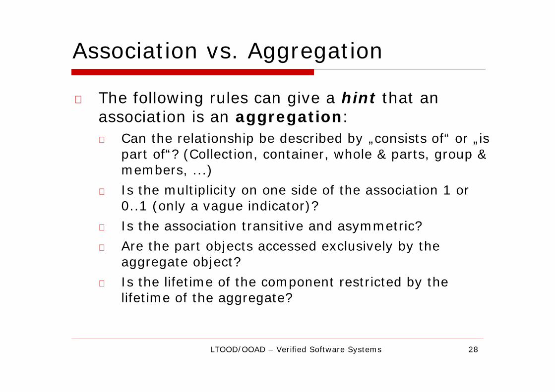
Association vs. Aggregation
o The following rules can give a hint that an
association is an aggregation:
n Can the relationship be described by „consists of“ or „is
part of“? (Collection, container, whole & parts, group &
members, ...)
n Is the multiplicity on one side of the association 1 or
0..1 (only a vague indicator)?
n Is the association transitive and asymmetric?
n Are the part objects accessed exclusively by the
aggregate object?
n Is the lifetime of the component restricted by the
lifetime of the aggregate?

29LTOOD/OOAD – Verified Software Systems
Aggregation vs. Composition
o Properties of aggregation:
n an aggregation is a specific semantic relationship between
aggregate and component B. “B is a part of A.”
o Additional properties of composition:
n a composition is an aggregation with the additional
property of dependent existence of the component
n exclusive aggregation (component can only be component of
a single aggregate)
Aggregate
Component
Aggregation
Order
Position
0..1
*
University
ResearchGroup
1
*
Composition

30LTOOD/OOAD – Verified Software Systems
Role
o A role has a name and describes the meaning of
the classes participating in an association more
precisely.
Lecture Professor
* *can teach
* *
teaches
Teaching field
Teaching offer
Available lecturer
Lecturer
Role nameAssociation
name

31LTOOD/OOAD – Verified Software Systems
Association Multiplicities: Summary
o The multiplicity of an association defines the
valid range of values for the number of objects
taking part in the association (cardinalities).
MeaningExamplesNotation
[number, infinity]0..*, 4..*number..*
0..***
[number1, number2]1..5, 2..10number1..number2
exactly this many1, 4number

32LTOOD/OOAD – Verified Software Systems
Generalization
o Generalization is a semantic relationship between a
more general concept A (super class) and a more
special concept B (sub class).
o For classes: Inheritance builds a taxonomy.
Generaliz
atio
n
Specia
lization
Employee
Freelancer Staff
Employee
Freelancer Staff
Super class
Sub class
Taxonomy: a hierarchical
classification of things

33LTOOD/OOAD – Verified Software Systems
Object Diagrams (vs. Class Diagrams)
o An object diagram shows objects (instances)
at a certain point in time.
n can also show states and
relationships
o Elements of ODs:
n objects
n references a2: Article
name=“teacup”
hw: Customer
customerNo=14
name=“Holm”
(directed) Reference
b: Order
date=18.5.1999a1: Article
name=“teapot”
object class name
name of the instance

34LTOOD/OOAD – Verified Software Systems
Example: Associations
Order: Customers may issue several orders.
Each order belongs to a customer.
An order is never related to more than one customer.
Association
CustomerOrder
1*
Multiplicities

35LTOOD/OOAD – Verified Software Systems
Example: Generalization
We distinguish corporate customers from personal customers, since
corporate customers are billed monthly whereas personal customers
need to prepay their orders with a credit card.
CustomerOrder
1*
Corporate
Customer
Personal
Customer
Generalization

36LTOOD/OOAD – Verified Software Systems
Example: More Associations
Order:
We want our orders to be lined up product by product.
Each line should contain the amount and the price of each product.
CustomerOrder
1*
Corporate
Customer
Personal
Customer
Order Line
1
*
Product1*
Line item

37LTOOD/OOAD – Verified Software Systems
Example: Attributes & Operations
We have customers who order our products.
We distinguish corporate customers from personal customers, since
corporate customers are billed monthly whereas personal customers
need to prepay their orders with a credit card.
We want our orders to be lined up product by product.
Each line should contain the amount and the price of each product.
Customer
Order
dateReceived
isPrepaid
number:String
price:Money
name
address
Attributes

38LTOOD/OOAD – Verified Software Systems
Example: Order - Full Class Diagram
Order
dateReceived
isPrepaid
number:String
price:Money
Order Line
Customer
Corporate
Customer
Personal
Customer
Product Employee
quantity:Integer
price:Money
isSatisfied:Bool
contactName
creditRating
creditLimit
name
address
creditCard#
* 1
1
1
0..1
*
* *
Multiplicity: mandatory
Association
Generalization
{If Order.customer.creditRating
is “poor”, then Order.isPrepaid
must be true}
Constraint
Attributes
Multiplicity: multi-valued
Role name
Line item
Multiplicity: optional

39LTOOD/OOAD – Verified Software Systems
Modeling System Behaviour

40LTOOD/OOAD – Verified Software Systems
Modeling of System Behavior
o How do systems behave?
o Modeling system behavior is so much harder
than modeling system structure
o Use cases ⇒
n scenarios/processes interaction diagrams
n workflows activity diagrams

41LTOOD/OOAD – Verified Software Systems
Activity Diagrams
o Elements
n States
n Actions, Activities
n Transitions
n Branches, Merge
n Concurrency, Synchronization
n Swimlanes, Object Flow
n Signals

42LTOOD/OOAD – Verified Software Systems
Role of Activity Diagrams in UML
Use Case
Diagrams
State Diagrams
Visualization of high-level
reaction to events
Activity Diagrams
Workflow presentation
Legend:
A delegates task
to B
A B
Interaction
Diagrams
Refinement of
timing and sequence

43LTOOD/OOAD – Verified Software Systems
Specification of Behavior
o Computer Science developed several models
for behavior specification
n logic-oriented models: predicate transformers on
pre- and post-conditions
n graph-oriented models:
o Petri nets
o state machines
o activity diagrams
o Goals
n Specification of state changes of an object (or an
interaction) triggered by an external event or a
received signal.
n Definition of protocols, i. e., legal sequences of
operations of a class or an interface.

44LTOOD/OOAD – Verified Software Systems
Activity Diagrams
o The states are action states or activity states
and the transitions are fired (triggered) by the
termination of activities.
o In activity diagrams the concept of state does
not refer to a static situation, but to named
clusters of acts.
Choose site
Survey house
State
Transition
Example: Building a house

45LTOOD/OOAD – Verified Software Systems
Transitions
o Transitions describe
how to get from one
state into another.
o A transition is
executed when the
previous action or
activity is terminated.
Chose site
Survey House
Start state
Final state
Transition
Action or Activity
46LTOOD/OOAD – Verified Software Systems
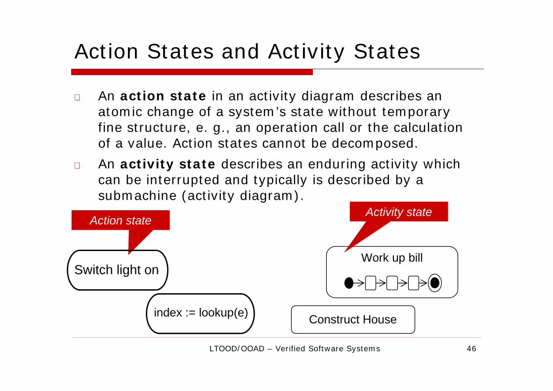
Action States and Activity States
o An action state in an activity diagram describes an
atomic change of a system’s state without temporary
fine structure, e. g., an operation call or the calculation
of a value. Action states cannot be decomposed.
o An activity state describes an enduring activity which
can be interrupted and typically is described by a
submachine (activity diagram).
Construct House
Action state
Work up bill
Activity state
Switch light on
index := lookup(e)

47LTOOD/OOAD – Verified Software Systems
Activity States: Actions
o In activity states actions can be executed at
the beginning (entry point) or end (exit point)
of an activity.
Construct House
entry / call architect
exit / pay architect
Point in time
Drive Car
entry / radio on
do / steer car
exit / radio off
Action

48LTOOD/OOAD – Verified Software Systems
Additional Reference
o Book (from the “I want to model X, how do I do that
with UML?” perspective)
n G. Booch, J. Rumbaugh, I. Jacobson. The Unified
Modeling Language User Guide. Addison-Wesley 1999