friend finder armband
TRANSCRIPT

University of Illinois
Department of Electrical and Computer Engineering
Tim Capota and Dave Drake
Friend Finder Armband
Design Review
TA: Jane Tu
02/22/2012
Team #30

2
Table of Contents 1. Introduction ................................................................................................................................................ 3
1.1 Motivation ...................................................................................................................................................... 3
1.2 Objectives ....................................................................................................................................................... 3
2. Design .......................................................................................................................................................... 3
2.1 Block Diagram ................................................................................................................................................. 4
2.2 Schematics ...................................................................................................................................................... 4
2.3 Microcontroller Flowchart .............................................................................................................................. 9
2.4 Block Descriptions ........................................................................................................................................ 10
2.5 Calculations ................................................................................................................................................... 10
3. Requirements and Verification ................................................................................................................. 12
3.1 Performance Requirements ......................................................................................................................... 12
3.2 Testing Procedures ....................................................................................................................................... 12
3.3 Tolerance Anaylsis ........................................................................................................................................ 14
4. Cost and Schedule ..................................................................................................................................... 16
4.1 Cost ............................................................................................................................................................... 16
4.2 Schedule ....................................................................................................................................................... 17
5. Ethical Considerations .............................................................................................................................. 19
6. References ................................................................................................................................................. 19

3
1. Introduction
1.1 Motivation: Many times GPS devices can not be used to locate a person in a big crowd. They are not accu-
rate enough to tell you exactly where a person is within close distances, and sometimes the signal is unreliable.
The friend finder armband aims to fill this void in the market by creating an intuitive tool to easily find others
which works where GPS does not. Our product would be useful in a myriad of situations including concerts,
malls, and any other events where large gatherings of people make getting separated easy.
1.2 Objectives: Our goal is to develop a compact armband that will allow the users to easily locate each other
in any situation. The armbands will use a system of antennas to locate each other. There will be increasing vi-
bration with increasing proximity. Moreover, the armbands will have LED's to point the user in the right direc-
tion.
Features:
Sends and receives position wirelessly.
LED display to indicate direction of other armband.
Vibrates more intensely with increasing proximity.
Benefits:
Easily locate friends in a large crowd
Works when GPS does not
User friendly interface
Robust design to be used in almost any situation

4
2. Design
2.1 Block Diagram:
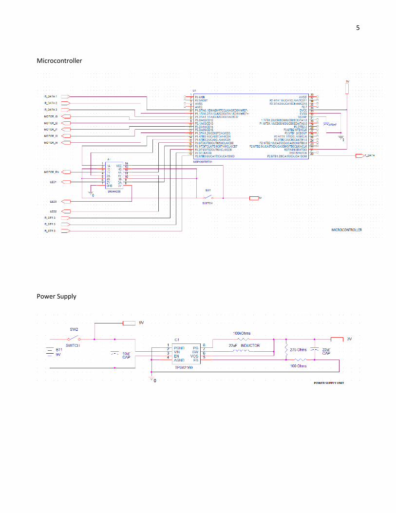
2.2 Schematics
LED Display
Power Supply
Micro Con-
troller
LEDs
Motor
Transmitter
Receiver
5
Microcontroller
Power Supply

6
Motor

7
Transmitter

8
Receiver

9
2.3 Microcontroller Flowchart
Start
Incoming
Data?
No
Yes
Record RSSI Values
Compare RSSI Values
One Signal
Strongest? Corresponding
LED On
Greater Than
Magnitude
at 50ft?
NO
Set Current Level for Motor
YES
Two Signals
Strongest? Corresponding
LEDs On
Turn On All LEDs and Motor
YES
NO
NO
YES

10
2.4 Block Descriptions:
Power Supply: The main power will be from a 9V DC battery. There is also a DC/DC converter IC to step the
voltage down to 3V. The power supply gives 3V power to the motor, microcontroller, transmitter, and receiver.
The power supply sends 9V to the motor driver.
LEDs: This module contains three LEDs that indicate the direction of the paired armband. The LEDs each receive
a signal from the microcontroller telling them when to turn on. The LEDs get power from the microcontroller.
There is also a switch that is ANDed with the signal from the microcontroller, giving the user the ability to turn
off the user interface.
Motor: The motor module contains the motor driver and the motor. The motor driver receives an enable
command from the microcontroller indicating when vibration is required. This enable is also ANDed with a
switch giving the user the ability to turn off the user interface. The motor driver also receives 5 bits from the
microcontroller to control the current level given to the motor; this regulates the intensity of the motor vibra-
tion. The motor driver gives the required current to the motor. As the proximity increases the microcontroller
will tell the motor driver to increase the current into the motor. The motor gets 3V from the power supply.
Microcontroller: This is the main brains of our design. The microcontroller sends data to the transmitter to
send. It receives incoming data from the receiver and the RSSI (received signal strength) information. The in-
coming data from the receiver is line passed and uses the digital in/out ports, not requiring A/D conversion. By
comparing the strength of the received signals (from the RSSI values) it will control the LEDs to indicate posi-
tion. Each LED corresponds to the direction of each antenna respectively. It will use the magnitude of the
strongest signal to control the motor driver, telling it to make the motor vibrate more intensely with stronger
reception. The LED and motor enables are ANDed with a switch giving the user the ability to turn off the user
interface. The microcontroller gets 3V from the power supply.
Transmitter: This module will transmit a signal over a single antenna indicating the presence of the friend find-
er armband. It receives data from the microcontroller to transmit. The transmitter gets 3V from the power
supply.
Receiver: This module will use three antennas and receivers to receive the signal transmitted from the other
armband. They each output the incoming data (sent from the transmitter) and the RSSI (received signal
strength) to the microcontroller. The receiver gets 3V from the power supply.
2.5 Calculations
Received Signal Strength
- Friis Equation. [1]
Where Pr is power received, Pt is power transmitted, Gr and Gt the antenna gains, d is the distance,
and n is the loss parameter. From [1], n was found to be about 1.7981 for indoor environments. The Xbee-PRO
transceiver transmits at a frequency of 2.4 Ghz, which corresponds to a λ=.125m. Gr and Gt for the Xbee-PRO is
1.412 which was calculated from the Xbee-PRO data sheet which gave gain in dBi. [2]

11
Using Friis Equation and the specifications of the Xbee-Pro transceiver, we can calculate the difference in RSSI
between signals received at each of the 3 triangulation antennas. In these calculations we assumed an antenna
spacing of 7cm, or .07m. The RSSI signal is represented by 8 bits and has a range from -36 dBm to -100 dBm. [3]
This means that we can discern changes in RSSI as small as .25 dBm.
For Pt of 10 dBm:
At d=1m, Pr= -27.04 dBm. This is not a discernible change because the RSSI output will default to -36 since this
number is below the rating.
At d=3.3m (10ft), Pr=-36.4dBm. This is when we can start to tell changes in proximity (hence vibrations increase
up to this point).
At d=30m, Pr = -53.6 dBm. At d=30.07m, Pr= -53.63 dBm which is not a discernible change. To resolve this, we
plan on using RF shielding to create a more directional antenna, so only signals incoming from a specific direc-
tion will be detected, thereby giving a more accurate location.
The geometry of our design is shown below:
Solving for α with the requirement that we can detect radiation from any direction 1m away, we get that α=87
degrees. Knowing that each antenna is equally spaced at 10cm, we can find that the angle subtended by our
shield should be equal to 360-60-87-87=126 degrees. Any angle larger then this will give us complete coverage
past 1 meter.
Battery Life
The battery life was calculated using specifications from the datasheets [4]-[10]. The Amps drawn from the
system that use 3V are:
1m
1m
1m
.05mα

12
XBee-PRO transmitter: 215mA
XBee-PRO receiver: 55mA*3
LEDs: 30mA*3
Motor: 53mA
Microcontroller: 2mA
This totals to 525mA, which corresponds to 1575mW of power. All these components go through the
DC/DC converter with an effieciency of 85%. Therefore the actual power drawn from the battery is
1853mW. The motor driver draws draws 192mW. So the total load is 2045mW, which means this is a
227mA load. From the datasheet for the battery the lifetime is 750mAh for 200mA discharge. This gives a
lifetime of 6750mWh. Therefore the friend finder armband should last approximately 3.3 hours. By having
two batterys in parallel the lifetime should double.
3. Requirements and Verification
3.1 Performance Requirements
Indicate location via LEDs from 3ft to 200ft outdoors
Indicate location via LEDS from 3ft to 100ft indoors
Indicate location via LEDS from 3ft to 200ft outdoors
Accuracy of directionality of 60 +/- 30 degrees
Indicate close proximity via vibration from 10ft to 50ft
Armband lasts at least 5 hours
3.2 Testing Procedures:
The friend finder armband consists of 6 modules which all contribute to the overall function of our de-
sign. At the highest level, the friend finder armband must be able to transmit its location, detect the direction
and strength of the other armbands transmission, and notify the user via vibration and LEDs.
Requirement Verification
Microcontroller
1. Microcontroller detects differences between
incoming signals and sends signals to LEDs.
a. Microcontroller gets RSSI signals from
all three antennas.
b. Microcontroller compares stored sig-
nals to calculate which are greatest
and sends correct signals to LEDs.
1. The circuit will be connected to three differ-
ent signal generators, and the Motor_En, LED
1, LED 2, and LED 3 signals will be connected
to an oscilloscope. The incoming signals from
the signal generators should be compared,
and the LED corresponding to the strongest
signal or signals should be high.
a. We will have microcontroller output
signals it is receiving from signal gen-

13
erator to other output pins. These will
be read on an oscilloscope. If the sig-
nal is above 2.5V when high and lower
than .5V when low the test has
passed.
b. Correct LED signal is above 2.5V based
on highest input from signal genera-
tor.
2. Microcontroller correctly activates and con-
trols magnitude of vibration
a. Microcontroller finds strongest signal
and stores magnitude.
b. Microcontroller compares magnitude
of stored RSSI signal with that of
stored reference signal from 50 ft.
c. Microcontroller sends appropriate 5-
bit current control to motor.
2. The microcontroller will be connected to
three signal generators and the pins I0-I4 will
be measured on an oscilloscope.
a. Have microcontroller output the
magnitude of the strongest signal to
an unused I/O pin read on oscillo-
scope. If the binary valueis the same
as that of the signal generator then
the test has passed.
b. Output stored reference signal (value
will be gotten from testing) and en-
sure it is the same. Output difference
between it and incoming strongest
signal. If the difference matches what
we calculate the test has passed.
c. Output correct current control bits
through I0-I4. For every ~3% change
in magnitude we will increment the
current.
Transceiver
3. Accuracy of directionality of 60 +/- 30
a. Antenna’s receive signals only within
180 degrees
3. One receiver will be rotated, while the trans-
mitter will remain in place. The output signal
strength will be measured on an oscilloscope.
a. Output signal is at least 20dB higher in
the 180 degrees in front of the anten-
na.
4. Transmitter sends signal
a. Transmitter able to receive serial data
from microcontroller
b. Transmitter sends serial data Omni di-
rectionally
4. Function Generator will be connected to the
data in pin on the transmitter and the data
out pin on the receiver will be hooked up to
an oscilloscope to check for correct transmis-
sion. The receiver will be moved in all direc-

14
tions.
a. Oscilloscope has same binary values
on receiver as generated.
b. Oscilloscope reads a signal greater
than 2.5V in all directions.
5. Receiver receives signal up to 100ft indoors
and 200ft outdoors.
a. Receiver gets incoming serial data up
to 100ft indoors.
b. Receivers get incoming serial data up
to 200ft outdoors.
5. Function generator will be used to send a sig-
nal from the transmitter. The receiving anten-
na will be placed at the corresponding dis-
tance for each test. Oscilloscope will be con-
nected to the receiver to read the incoming
signal.
a. Oscilloscope shows same binary val-
ues at 100ft indoors.
b. Oscilloscope shows same binary val-
ues at 200ft outdoors.
User Interface
6. Motor vibrates more or less intensely
a. Motor begins vibrating when enable
signal is high
b. Motor vibrates more intensity with
larger current control signal
6. Motor enable and current control signals will
be connected to an outside power supply and
ground to give logic signals to the motor. An
oscilloscope will be used to read the output
current from the motor driver.
a. When motor enable is greater than
2.5V, motor will vibrate.
b. As the current control bits are incre-
mented the current is at the correct
percentage of 60mA according to ta-
ble 3 of the motor diver datasheet.
7. LEDs illuminate when active. 7. LEDs will be connected to an outside power
supply and resistive network. When 3V
(20mA) is supplied to LEDs they will light up.
Power Supply
8. Power supply gives correct voltages at out-
puts.
9. Power supply will be hooked up to an oscillo-
scope. Above 8.5V will be read at the supply
to motor. Above 2.5V will be read at other
supply output.

15
Entire Project
9. Armband lasts at least 5 hours 8. Armbands will be left with all the LEDs on and
the motor vibrating for 5 hours. After five
hours armbands will be checked.
3.3 Tolerance Analysis
The transceiver is the key component in this device since it is the one used to detect the other
armband. An important part of the friend finder armband will be the ability to transmit despite arm
orientation. This way if you are trying to find your friend you can locate them despite what they are do-
ing. We will test that the receiver can locate the transmitter at a variety of orientations. We require
that our tolerance be +/- 30 degrees when the antennas are perpendicular to each other. The reason
for this is that radiation from antennas oscillates in one axis, and cannot be received in a orthogonal ax-
is. This is illustrated in the figures shown below:
Figure 1. Radiation pattern from omni-directional antenna [11]

16
Figure 2. Defining rotation angles
Here, rotation in alpha causes the null to point towards the transmitter, while rotation in beta
causes the oscillation of the receiver to be orthogonal to that of the transmitter.
The friend finder armband is designed to work when armbands are in the same room. But we
would like to test the tolerance of our system when walls and other objects impede our transmission.
We will find the tolerance for the number of walls we can propagate through while still getting accu-
rate measurements.
4. Cost and Schedule
4.1 Cost Analysis
Parts
Part Quantity Price Total Cost
TI MSP430FR5731 2 $1.95 $3.90
Xbee-Pro 802.15.4 8 $38.00 $304.00
α
β

17
TI DRV8840 2 $6.92 $13.84
Pico Vibe 12mm Vibration Motor –
3.4mm type
2 $6.68 $13.36
LED-117 Ultra Bright Blue 6 $.82 $4.92
Energizer LA522 4 $7.00 $28.00
PB-94 DPDT Push Button Switch 4 $1.37 $5.48
TI TPS62160 2 $1.71 $3.42
TI SN54AC08 2 $2.20 $4.40
Capacitors 9 $1.40 $12.60
Resistors 4 $0.20 $0.80
Total Parts Cost: $394.72
Labor
Name Rate Hours Total Total * 2.5
Tim Capota $40/hr 240 $9,600 $24,000
Dave Drake $40/hr 240 $9,600 $24,000
Total Labor Cost: $48,000
Total Cost: $48,394.72
4.2 Schedule
Date Task Group Member(s)
6-Feb Finish Proposal
Research Microcontroller/Motor
Research Transmitter/Receiver
All
Dave
Tim
13-Feb Sign Up for Design Review All

18
Design RF
Design Microcontroller
Design PSU
Tim
Dave
Tim
20-Feb Design Review All
27-Feb Order RF/Microcontroller
Order PSU/Misc. parts
Order LEDs/Motor
Tim
Dave
Dave
5-Mar Build PSU
Build RF system
Dave
Tim
12-Mar Build LED/Motor
Program Microcontroller
Tim
Dave
19-Mar Spring Break
26-Mar Prepare for Mock-up Presentation
Build armband 1
Build armband 2
All
Dave
Tim
2-Apr Mock-up Presentation
Test RF system
Test LED/Motor
All
Tim
Dave
9-Apr Tolerance Analysis
Debugging
Dave
Tim
16-Apr Preparation for Demo/Presentation All
23-Apr Demo/Presentation All
30-Apr Demo/Presentation/Checkout All

19
5. Ethical Considerations
Safety is an important consideration when taking on any electrical engineering project. The IEEE code
of ethics #1 states: “to accept responsibility in making decisions consistent with the safety, health and welfare
of the public, and to disclose promptly factors that might endanger the public or the environment;” As with any
electronic device, shock is always a safety concern. Therefore, we will ensure that all connections posing any
threat are shielded from the user and power levels are less than those which could cause serious injury.
6. References
[1] E. Goldoni et al, “Experimental Analysis of RSSE-based Indoor Localization with IEEE 802.15.4,” in 2010
European Wireless Conference. [Online]. 2010, pp. 71-77. Available:
http://ieeexplore.ieee.org/stamp/stamp.jsp?arnumber=05483396&tag=1
[2] Xbee/Xbee-PRO RF Modules Product Manual v1.Ex– 802.15.4. Digi International Inc. [Online]. Available:
http://ftp1.digi.com/support/documentation/90000982_F.pdf
[3] D. Gascón and M. Yarza. (2008 Nov.) Indoor location using 802.15.4 – ZigBee. [Online]. Available:
http://www.sensor-networks.org/index.php?page=0827027001
[4] LA522 Datasheet. Energizer. [Online]. Available:
http://data.energizer.com/PDFs/LA522_EU.pdf
[5] MSP430FR5731 Datasheet. Texas Instruments. [Online]. Available:
http://www.ti.com/lit/ds/slas639b/slas639b.pdf
[6] DRV8840 Datasheet. Texas Instruments. [Online]. Available:
http://www.ti.com/lit/ds/slvsab7b/slvsab7b.pdf
[7] TPS62160 Datasheet. Texas Instruments. [Online]. Available:
http://www.ti.com/lit/ds/slvsam2/slvsam2.pdf
[8] Xbee-Pro 802.15.4 Datasheet. Digi International Inc. [Online]. Available:
http://www.digi.com/pdf/ds_xbeemultipointmodules.pdf
[9] TI SN54AC08 Datasheet. Texas Instruments. [Online]. Available:
http://www.ti.com/lit/ds/scas536d/scas536d.pdf
[10] Pico Vibe 12mm Vibration Motor – 3.4mm Type Datasheet. Precision Microdrives. [Online] Available:

20
https://catalog.precisionmicrodrives.com/order-parts/product/312-101-12mm-vibration-motor-3-
4mm-type
[11] Antennae. [Online]. Available:
http://som.csudh.edu/fac/lpress/471/hout/wireless/antennae.htm